


 Loading...
DTAM Micro
Operator Interface
Module
Catalog Numbers 2707-M232P3,
2707-M485P3
User Manual

Important User Information Because of the variety of uses for the products described in this publication, those responsible for the application and use of this control equipment must
satisfy themselves that all necessary steps have been taken to assure that each application and use meets all performance and safety requirements, including any applicable laws, regulations, codes and standards.
The illustrations, charts, sample programs and layout examples shown in this guide are intended solely for purposes of example. Since there are many variables and requirements associated with any particular installation, Allen-Bradley does not assume responsibility or liability (to include intellectual property liability) for actual use based upon the examples shown in this publication.
Allen-Bradley publication SGI-1.1, Safety Guidelines for the Application, Installation and Maintenance of Solid-State Control (available from your local Allen-Bradley office), describes some important differences between solid-state equipment and electromechanical devices that should be taken into consideration when applying products such as those described in this publication.
Reproduction of the contents of this copyrighted publication, in whole or part, without written permission of Rockwell Automation, is prohibited.
Throughout this manual we use notes to make you aware of safety considerations:
|
Identifies information about practices or |
|
ATTENTION |
||
circumstances that can lead to personal injury or |
||
|
||
|
death, property damage or economic loss |
!
Attention statements help you to:
•identify a hazard
•avoid a hazard
•recognize the consequences
|
Identifies information that is critical for successful |
|
IMPORTANT |
||
application and understanding of the product. |
||
|
||
|
||
|
|
Allen-Bradley, DTAM Micro and SLC are trademarks of Rockwell Automation PLC is a registered trademark of Rockwell Automation

Using this Manual
DTAM Micro Overview
Initial Setup and Mode
Menu
Table of Contents
DTAM Micro Operator Interface Module
User Manual
Chapter 1
Objectives . . . . . . . . . . . . . . . . . . . . . . . . . . . . . . . . . . . . . . . . . . . . . . . . . |
1–1 |
Contents of this Manual . . . . . . . . . . . . . . . . . . . . . . . . . . . . . . . . . . . . . . . |
1–1 |
Intended Audience . . . . . . . . . . . . . . . . . . . . . . . . . . . . . . . . . . . . . . . . . . . |
1–2 |
Conventions . . . . . . . . . . . . . . . . . . . . . . . . . . . . . . . . . . . . . . . . . . . . . . . |
1–2 |
Related Publications . . . . . . . . . . . . . . . . . . . . . . . . . . . . . . . . . . . . . . . . . |
1–2 |
Chapter 2
Objectives . . . . . . . . . . . . . . . . . . . . . . . . . . . . . . . . . . . . . . . . . . . . . . . . . |
2–1 |
General Information . . . . . . . . . . . . . . . . . . . . . . . . . . . . . . . . . . . . . . . . . . |
2–1 |
Package Contents . . . . . . . . . . . . . . . . . . . . . . . . . . . . . . . . . . . . . . . . . . . |
2–2 |
Description . . . . . . . . . . . . . . . . . . . . . . . . . . . . . . . . . . . . . . . . . . . . . . . . |
2–2 |
Keypad . . . . . . . . . . . . . . . . . . . . . . . . . . . . . . . . . . . . . . . . . . . . . . . . . . . |
2–5 |
Function Key Operations . . . . . . . . . . . . . . . . . . . . . . . . . . . . . . . . . . . . |
2–6 |
MODE Key Operations . . . . . . . . . . . . . . . . . . . . . . . . . . . . . . . . . . . . . . |
2–6 |
DIP Switches . . . . . . . . . . . . . . . . . . . . . . . . . . . . . . . . . . . . . . . . . . . . . . . |
2–7 |
Communications Port . . . . . . . . . . . . . . . . . . . . . . . . . . . . . . . . . . . . . . . . . |
2–8 |
RS-232 Version (Catalog No. 2707-M232P3) . . . . . . . . . . . . . . . . . . . . . . |
2–9 |
RS-232 Communications . . . . . . . . . . . . . . . . . . . . . . . . . . . . . . . . . . . . . . |
2–9 |
RS-485 Version (Catalog No. 2707-M485P3) . . . . . . . . . . . . . . . . . . . . . . |
2–10 |
RS-485 Communications . . . . . . . . . . . . . . . . . . . . . . . . . . . . . . . . . . . . . . |
2–10 |
Compatibility . . . . . . . . . . . . . . . . . . . . . . . . . . . . . . . . . . . . . . . . . . . . . . . |
2–11 |
Programming the DTAM Micro . . . . . . . . . . . . . . . . . . . . . . . . . . . . . . . . . . |
2–12 |
DTAM Plus Programming Software (DPS) . . . . . . . . . . . . . . . . . . . . . . . . |
2–12 |
Upload/Download Connections . . . . . . . . . . . . . . . . . . . . . . . . . . . . . . . . |
2–12 |
Default Settings . . . . . . . . . . . . . . . . . . . . . . . . . . . . . . . . . . . . . . . . . . . . . |
2–13 |
Operating System . . . . . . . . . . . . . . . . . . . . . . . . . . . . . . . . . . . . . . . . . |
2–13 |
DIP Switch Settings . . . . . . . . . . . . . . . . . . . . . . . . . . . . . . . . . . . . . . . . |
2–13 |
Operating Parameters . . . . . . . . . . . . . . . . . . . . . . . . . . . . . . . . . . . . . . |
2–13 |
Product Options . . . . . . . . . . . . . . . . . . . . . . . . . . . . . . . . . . . . . . . . . . . . . |
2–14 |
Product Accessories . . . . . . . . . . . . . . . . . . . . . . . . . . . . . . . . . . . . . . . . . |
2–14 |
Chapter 3
Objectives . . . . . . . . . . . . . . . . . . . . . . . . . . . . . . . . . . . . . . . . . . . . . . . . . |
3–1 |
Apply Power . . . . . . . . . . . . . . . . . . . . . . . . . . . . . . . . . . . . . . . . . . . . . . . |
3–2 |
Powerup Sequence . . . . . . . . . . . . . . . . . . . . . . . . . . . . . . . . . . . . . . . . . . |
3–3 |
Mode Menu . . . . . . . . . . . . . . . . . . . . . . . . . . . . . . . . . . . . . . . . . . . . . . . . |
3–4 |
Resetting the DTAM Micro . . . . . . . . . . . . . . . . . . . . . . . . . . . . . . . . . . . . . |
3–5 |
Setting Communication Parameters Manually . . . . . . . . . . . . . . . . . . . . . . . |
3–6 |
Special Functions forController Operations . . . . . . . . . . . . . . . . . . . . . . . . . |
3–7 |
Entering a New Master Security Code . . . . . . . . . . . . . . . . . . . . . . . . . . . . . |
3–8 |
Enabling / Disabling Scaling . . . . . . . . . . . . . . . . . . . . . . . . . . . . . . . . . . . . |
3–9 |
i

Table of Contents
DTAM Micro Operator Interface Module
User Manual
Using the Simulate Mode . . . . . . . . . . . . . . . . . . . . . . . . . . . . . . . . . . . . . . 3–10
Test Functions . . . . . . . . . . . . . . . . . . . . . . . . . . . . . . . . . . . . . . . . . . . . . . 3–11
Transferring Applications
Chapter 4
Objectives . . . . . . . . . . . . . . . . . . . . . . . . . . . . . . . . . . . . . . . . . . . . . . . . . |
4–1 |
Upload / Download DIP Switch Settings . . . . . . . . . . . . . . . . . . . . . . . . . . . . |
4–1 |
Upload / Download Connections . . . . . . . . . . . . . . . . . . . . . . . . . . . . . . . . . |
4–2 |
Computer Setup . . . . . . . . . . . . . . . . . . . . . . . . . . . . . . . . . . . . . . . . . . . . |
4–2 |
Downloading an Application . . . . . . . . . . . . . . . . . . . . . . . . . . . . . . . . . . . . |
4–3 |
Uploading an Application . . . . . . . . . . . . . . . . . . . . . . . . . . . . . . . . . . . . . . |
4–8 |
Running Applications
Installation
Chapter 5
Chapter Objectives . . . . . . . . . . . . . . . . . . . . . . . . . . . . . . . . . . . . . . . . . . |
5–1 |
DIP Switch Setting . . . . . . . . . . . . . . . . . . . . . . . . . . . . . . . . . . . . . . . . . . . |
5–1 |
Application Documentation . . . . . . . . . . . . . . . . . . . . . . . . . . . . . . . . . . . . . |
5–1 |
Bit Write Mode . . . . . . . . . . . . . . . . . . . . . . . . . . . . . . . . . . . . . . . . . . . . . . |
5–1 |
Screen Types . . . . . . . . . . . . . . . . . . . . . . . . . . . . . . . . . . . . . . . . . . . . . . |
5–2 |
Screen Navigation . . . . . . . . . . . . . . . . . . . . . . . . . . . . . . . . . . . . . . . . . . . |
5–2 |
Screen Links . . . . . . . . . . . . . . . . . . . . . . . . . . . . . . . . . . . . . . . . . . . . . |
5–2 |
Advisor Option . . . . . . . . . . . . . . . . . . . . . . . . . . . . . . . . . . . . . . . . . . . . |
5–2 |
Function Keys . . . . . . . . . . . . . . . . . . . . . . . . . . . . . . . . . . . . . . . . . . . . |
5–3 |
Menu and Sub-Menu Screens . . . . . . . . . . . . . . . . . . . . . . . . . . . . . . . . . . . |
5–4 |
Main Menu . . . . . . . . . . . . . . . . . . . . . . . . . . . . . . . . . . . . . . . . . . . . . . |
5–4 |
Sub-Menus . . . . . . . . . . . . . . . . . . . . . . . . . . . . . . . . . . . . . . . . . . . . . . |
5–4 |
Security Screens . . . . . . . . . . . . . . . . . . . . . . . . . . . . . . . . . . . . . . . . . . . . |
5–4 |
Data Display Screens . . . . . . . . . . . . . . . . . . . . . . . . . . . . . . . . . . . . . . . . |
5–5 |
Data Entry Screens . . . . . . . . . . . . . . . . . . . . . . . . . . . . . . . . . . . . . . . . . . |
5–5 |
Recipe Screens . . . . . . . . . . . . . . . . . . . . . . . . . . . . . . . . . . . . . . . . . . . . . |
5–6 |
Alarm Screens . . . . . . . . . . . . . . . . . . . . . . . . . . . . . . . . . . . . . . . . . . . . . . |
5–6 |
Chapter 6
Objectives . . . . . . . . . . . . . . . . . . . . . . . . . . . . . . . . . . . . . . . . . . . . . . . . . |
6–1 |
Safety Guidelines . . . . . . . . . . . . . . . . . . . . . . . . . . . . . . . . . . . . . . . . . . . |
6–1 |
Operating Environment . . . . . . . . . . . . . . . . . . . . . . . . . . . . . . . . . . . . . . . |
6–2 |
Enclosures . . . . . . . . . . . . . . . . . . . . . . . . . . . . . . . . . . . . . . . . . . . . . . . . |
6–2 |
Equipment Required . . . . . . . . . . . . . . . . . . . . . . . . . . . . . . . . . . . . . . . . . |
6–3 |
Clearances . . . . . . . . . . . . . . . . . . . . . . . . . . . . . . . . . . . . . . . . . . . . . . . . |
6–3 |
Mounting Dimensions . . . . . . . . . . . . . . . . . . . . . . . . . . . . . . . . . . . . . . . . . |
6–4 |
Cutout Template . . . . . . . . . . . . . . . . . . . . . . . . . . . . . . . . . . . . . . . . . . . . |
6–5 |
Installation . . . . . . . . . . . . . . . . . . . . . . . . . . . . . . . . . . . . . . . . . . . . . . . . |
6–6 |
Wire and Cable Length Restrictions . . . . . . . . . . . . . . . . . . . . . . . . . . . . . . . |
6–7 |
Connecting DC Power . . . . . . . . . . . . . . . . . . . . . . . . . . . . . . . . . . . . . . . . |
6–7 |
ii

Communication
Connections and Setup
Troubleshooting and
Maintenance
Specifications
Table of Contents
DTAM Micro Operator Interface Module
User Manual
Chapter 7
Chapter Objectives . . . . . . . . . . . . . . . . . . . . . . . . . . . . . . . . . . . . . . . . . . |
7–1 |
Wiring Guidelines . . . . . . . . . . . . . . . . . . . . . . . . . . . . . . . . . . . . . . . . . . . |
7–1 |
Connecting RS-232 Devices . . . . . . . . . . . . . . . . . . . . . . . . . . . . . . . . . . . . |
7–2 |
Connecting RS-485 Devices . . . . . . . . . . . . . . . . . . . . . . . . . . . . . . . . . . . . |
7–3 |
Communicating with a Logic Controller . . . . . . . . . . . . . . . . . . . . . . . . . . . . |
7–6 |
Communications Parameters . . . . . . . . . . . . . . . . . . . . . . . . . . . . . . . . . |
7–6 |
Communicating With a PLC-5 . . . . . . . . . . . . . . . . . . . . . . . . . . . . . . . . . . . |
7–7 |
Communicating With an SLC 5/03 . . . . . . . . . . . . . . . . . . . . . . . . . . . . . . . . |
7–8 |
Communicating With an SLC or Network . . . . . . . . . . . . . . . . . . . . . . . . . . . |
7–9 |
RS232 Communications with a MicroLogix 1000 . . . . . . . . . . . . . . . . . . . . . |
7–10 |
RS485/DH–485 Communications with a MicroLogix 1000 . . . . . . . . . . . . . . . |
7–11 |
Chapter 8
Chapter Objectives . . . . . . . . . . . . . . . . . . . . . . . . . . . . . . . . . . . . . . . . . . |
8–1 |
TroubleshootingRecommendations . . . . . . . . . . . . . . . . . . . . . . . . . . . . . . . |
8–1 |
Equipment Required . . . . . . . . . . . . . . . . . . . . . . . . . . . . . . . . . . . . . . . . . |
8–1 |
Common OperatingProblems . . . . . . . . . . . . . . . . . . . . . . . . . . . . . . . . . . . |
8–2 |
Error Messages . . . . . . . . . . . . . . . . . . . . . . . . . . . . . . . . . . . . . . . . . . . . . |
8–2 |
CommunicationError Codes . . . . . . . . . . . . . . . . . . . . . . . . . . . . . . . . . . . . |
8–4 |
Using the Test Functions . . . . . . . . . . . . . . . . . . . . . . . . . . . . . . . . . . . . . . |
8–5 |
DIP Switch Test . . . . . . . . . . . . . . . . . . . . . . . . . . . . . . . . . . . . . . . . . . . . . |
8–6 |
Display Test . . . . . . . . . . . . . . . . . . . . . . . . . . . . . . . . . . . . . . . . . . . . . . . |
8–7 |
Keyboard Test . . . . . . . . . . . . . . . . . . . . . . . . . . . . . . . . . . . . . . . . . . . . . . |
8–8 |
Communication Port Test . . . . . . . . . . . . . . . . . . . . . . . . . . . . . . . . . . . . . . |
8–9 |
RAM Test . . . . . . . . . . . . . . . . . . . . . . . . . . . . . . . . . . . . . . . . . . . . . . . . . |
8–10 |
System Memory Test . . . . . . . . . . . . . . . . . . . . . . . . . . . . . . . . . . . . . . . . . |
8–10 |
Program Memory Test . . . . . . . . . . . . . . . . . . . . . . . . . . . . . . . . . . . . . . . . |
8–11 |
TXEN Test . . . . . . . . . . . . . . . . . . . . . . . . . . . . . . . . . . . . . . . . . . . . . . . . |
8–12 |
Cleaning the Display Window . . . . . . . . . . . . . . . . . . . . . . . . . . . . . . . . . . . |
8–13 |
Appendix A
DTAM Micro Specifications . . . . . . . . . . . . . . . . . . . . . . . . . . . . . . . . . . . . . |
A–1 |
Agency Ratings . . . . . . . . . . . . . . . . . . . . . . . . . . . . . . . . . . . . . . . . . . . . . |
A–2 |
European Union Directive Compliance . . . . . . . . . . . . . . . . . . . . . . . . . . . . . |
A–2 |
iii

Table of Contents
DTAM Micro Operator Interface Module
User Manual
DTAM Micro Cable |
Appendix B |
|
Diagrams |
DTAM Micro Cables |
B–1 |
|
||
|
Catalog No. 2707-NC2 . . . . . . . . . . . . . . . . . . . . . . . . . . . . . . . . . . . . . . |
B–1 |
|
Catalog No. 2707-NC3 . . . . . . . . . . . . . . . . . . . . . . . . . . . . . . . . . . . . . . |
B–2 |
|
Catalog No. 2707-NC4 . . . . . . . . . . . . . . . . . . . . . . . . . . . . . . . . . . . . . . |
B–2 |
|
Catalog No. 2707-NC5 . . . . . . . . . . . . . . . . . . . . . . . . . . . . . . . . . . . . . . |
B–3 |
|
Catalog No. 2707-NC10 . . . . . . . . . . . . . . . . . . . . . . . . . . . . . . . . . . . . . |
B–4 |
|
Catalog No. 1747-CP3 . . . . . . . . . . . . . . . . . . . . . . . . . . . . . . . . . . . . . . |
B–5 |
DTAM Micro Special
Controller Functions
Appendix C
Objectives . . . . . . . . . . . . . . . . . . . . . . . . . . . . . . . . . . . . . . . . . . . . . . . . . |
C–1 |
Accessing Special Functions . . . . . . . . . . . . . . . . . . . . . . . . . . . . . . . . . . . |
C–1 |
Using the P-A/D Function . . . . . . . . . . . . . . . . . . . . . . . . . . . . . . . . . . . . . . |
C–2 |
Reading ControllerInput and Output Files . . . . . . . . . . . . . . . . . . . . . . . . . . . |
C–3 |
Reading / Writing Controller Status Files . . . . . . . . . . . . . . . . . . . . . . . . . . . |
C–4 |
Reading / Writing Controller Bit and Integer Files . . . . . . . . . . . . . . . . . . . . . |
C–5 |
Reading / Writing Controller Timer Files . . . . . . . . . . . . . . . . . . . . . . . . . . . . |
C–6 |
Reading / Writing Controller Counter Files . . . . . . . . . . . . . . . . . . . . . . . . . . |
C–8 |
Reading / Writing Controller Control Files . . . . . . . . . . . . . . . . . . . . . . . . . . . |
C–10 |
Reading / Writing Controller ASCII Files . . . . . . . . . . . . . . . . . . . . . . . . . . . . |
C–12 |
Reading / Writing Controller BCD Files . . . . . . . . . . . . . . . . . . . . . . . . . . . . |
C–14 |
Reading / WritingController Message Files . . . . . . . . . . . . . . . . . . . . . . . . . . |
C–15 |
Reading Controller ASCII String Files . . . . . . . . . . . . . . . . . . . . . . . . . . . . . |
C–17 |
Using the Mode Function . . . . . . . . . . . . . . . . . . . . . . . . . . . . . . . . . . . . . . |
C–18 |
Using the Memory Transfer Function . . . . . . . . . . . . . . . . . . . . . . . . . . . . . . |
C–19 |
Using the Clear Fault Function . . . . . . . . . . . . . . . . . . . . . . . . . . . . . . . . . . |
C–20 |
iv

Chapter 1
Using this Manual
Objectives
Read this chapter to familiarize yourself with the rest of the manual. You will learn about:
•Contents of this manual
•Intended audience
•Conventions
•Related publications
Contents of this Manual
The following table lists the contents of each chapter:
Chapter |
Title |
Purpose |
|
|
|
|
|
1 |
Using this Manual |
Provides an overview of the manual. |
|
|
|
|
|
2 |
Overview of DTAM Micro |
Contains a description of the DTAM |
|
Micro and accessory devices. |
|||
|
|
||
|
|
|
|
3 |
Initial Setup and Main Menu |
Describes initial desktop setup of the |
|
DTAM Micro using main menu functions. |
|||
|
|
||
|
|
|
|
|
|
Describes how to upload and download |
|
4 |
Transferring Application Files |
application files between the DTAM Micro |
|
|
|
and a personal computer. |
|
|
|
|
|
|
|
Describes the basic screen types. |
|
5 |
Running Applications |
Also describes the different function |
|
|
|
key operations. |
|
|
|
|
|
|
|
Provides procedures for mounting the |
|
6 |
Installation |
DTAM Micro. Also provided are wiring |
|
|
|
instructions and recommendations. |
|
|
|
|
|
|
Communication |
Describes RS-232 and RS-485 |
|
7 |
connections. Setup guidelines are |
||
Connections and Setup |
|||
|
provided for SLC and PLC controllers. |
||
|
|
||
|
|
|
|
|
|
Provides assistance in identifying |
|
8 |
Troubleshooting |
and correcting common operating |
|
and Maintenance |
problems. Cleaning recommendations |
||
|
|||
|
|
are also provided. |
|
|
|
|
|
|
|
Provides the specifications, agency |
|
Appendix A |
Specifications |
ratings, and European Union Directive |
|
|
|
Compliance. |
|
|
|
|
|
Appendix B |
Cable Diagrams |
Provides the DTAM Micro cable |
|
diagrams. |
|||
|
|
||
|
|
|
|
Appendix C |
DTAM Micro Special |
Provides the special control functions. |
|
Controller Functions |
|||
|
|
1–1

Chapter 1
Using this Manual
Intended Audience
Conventions
Related Publications
No special knowledge is required to operate the DTAM Micro. If you are installing the DTAM Micro, you must be familiar with the standard panel cutout and installation techniques. If you are wiring the DTAM Micro, you must be familiar with the electrical codes in your area (see inside front cover).
You should be familiar with the DTAM Programming Software (see related publications below).
This manual uses the following conventions:
•Keys that you press on the DTAM Micro are enclosed in brackets [ ]. For example: [NEXT] refers to the NEXT key on the DTAM Micro.
•References to menus are initial cap followed by the word Menu. For example: Special Menu, Main Menu, Other Menu
•All DTAM Micro displays are shown inside a rectangular box.
1 Reset |
3 Special |
2 Com-Port |
4 Other |
The following publications may be helpful for additional reference.
DTAM Micro Publications
Publication Number |
Title |
|
|
|
|
2707-801 |
DTAM Programming Software Programming Manual |
|
(Series J or later Software) |
||
|
Wiring Publications
1770-6.2.2 |
Data Highway / Data Highway Plus / Data Highway-485 |
|
Cable Installation Manual |
||
|
||
SLC Publications |
|
Publication Number |
Title |
|
|
|
|
1747-6.21 |
SLC 500 Fixed Hardware Style |
|
Installation and Operation Manual |
||
|
||
|
|
|
1747-UM011 |
SLC 500 Modular Hardware Style |
|
Installation and Operation Manual |
||
|
||
|
|
|
1747-RM001 |
SLC 500 Reference Manual |
1–2

Chapter 1
Using this Manual
PLC-5 Publications
Publication Number |
Title |
|
|
|
|
1785-6.1 |
PLC-5 Instruction Set Reference |
|
|
|
|
1785-6.2.1 |
1785 PLC-5 Programmable Controllers Design Manual |
|
|
|
|
1785-6.6.1 |
PLC-5 Family Programmable Controllers Hardware |
|
Installation Manual |
||
|
||
|
|
|
1785-7.1 |
PLC-5 Programmable Controllers Quick Reference |
|
MicroLogix Publications |
|
Publication Number |
Title |
|
|
1747-6.3 |
MicroLogix 1000 User Manual |
|
|
1747-6.2.1 |
MicroLogix 1000 Quick Reference Guide |
1–3

Chapter 1
Using this Manual
1–4
Chapter 2
DTAM Micro Overview
Objectives
General Information
This chapter describes the DTAM Micro and accessories.
It contains these sections:
Section |
Page |
|
|
General Information |
2–1 |
|
|
Package Contents |
2–2 |
|
|
Description |
2–2 |
|
|
Keypad |
2–5 |
|
|
DIP Switches |
2–7 |
|
|
Communications Port |
2–8 |
|
|
RS-232 Communications |
2–9 |
|
|
RS-485 Communications |
2–10 |
|
|
Compatibility |
NO TAG |
|
|
Programming the DTAM Micro |
2–11 |
|
|
Default Settings |
2–12 |
|
|
Product Options |
2–13 |
|
|
Product Accessories |
2–13 |
The DTAM Micro interfaces with the PLC-5 and SLC 500 family of processors. The DTAM Micro allows operators to monitor and manipulate process data on the plant floor.
RS-232 or RS-485 Port. The DTAM Micro has either an RS-232 port (Catalog No. 2707-M232P3) or an RS-485 port (Catalog No. 2707-M485P3). The RS-232 port allows point-to-point connections with a PLC-5 or SLC 5/03, 5/04, 5/05. The RS-485 port provides network or point-to-point capability with a PLC-5 (over RS-422), SLC or other DH485 device.
Memory Capability. Storage of the PLC-5 DF1 or SLC DH-485 driver (communications protocol), configuration information, and user-programmed screens are maintained in nonvolatile memory providing storage for approximately 244 screens.
Recipe Operations. Recipe type functions allow operators to quickly modify blocks of data. Download data to a maximum of 10 non-sequential register addresses per screen. Link multiple recipe screens to download data to more than 10 addresses.
Flexible Function Key Operations. Eight function keys provide a convenient way to trigger screen displays and change display screens.
Point-Access/Display Function. Allows you to monitor or modify data files in SLC or PLC controllers. Use this function to setup and debug application programs.
2–1
Chapter 2
DTAM Micro Overview
Package Contents
Description
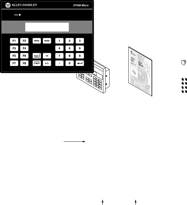
The DTAM Micro shipping box contains the following:
DIP Switch Cover
DTAM Micro
User Manual |
Mounting Nuts (8) |
(Catalog No. 2707–UM002) |
(2 Spare) |
The front panel of the DTAM Micro terminal is shown below.
Figure 2.1
DTAM Micro (front view)
LED Indicator
Display Window
Power Connector |
Communications Port |
Display
The 2 line by 20 character display uses high contrast LCD technology with LED backlighting.
Keypad
The keypad is separated by color into easily identified groups or functions. In addition, each key has a raised dome in the center to provide tactile feedback.
The keypad is designed for hand operation. Using any other object or tool may damage the overlay or key.
LED Indicator
A RUN LED in the upper left corner of the terminal indicates proper operation of the DTAM Micro. This LED illuminates after the DTAM Micro passes the self diagnostic tests.
2–2
Chapter 2
DTAM Micro Overview
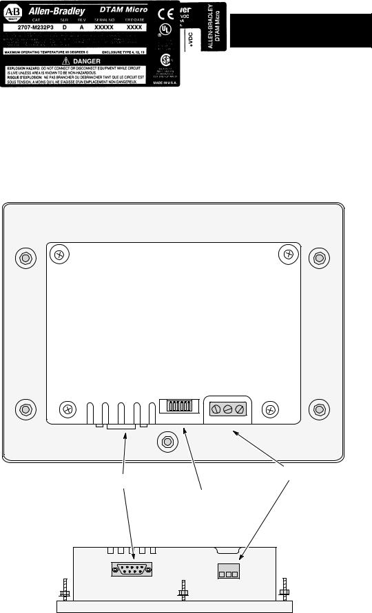
Figure 2.2
DTAM Micro (back & bottom view)
Back View (RS-232 version shown)
Power Connector
Communications Port
DIP Switch
(Behind Removable Cover)
Bottom View
2–3

Chapter 2
DTAM Micro Overview
Communications Port
The DTAM Micro has either an RS-232 or RS-485 port.
•Catalog No. 2707-M232P3 has RS-232 port
•Catalog No. 2707-M485P3 has RS-485 port
DIP Switch
A six position DIP switch selects various operating settings. This switch is located under a removable cover on the back. To remove cover, align cover tabs with notches in hole.
Power Connector
The power connector is a non-removable, screw terminal block located on the bottom of the unit. Connect 24 VDC to these terminals or use the optional AC to DC Adapter.
2–4
Keypad
Chapter 2
DTAM Micro Overview
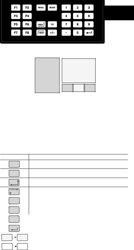
Figure 2.3
Keypad
The DTAM Micro uses a sealed membrane, tactile feedback keypad. The keys are color coded to easily identify key functions.
Key Color |
Function |
|
|
Blue |
Movement/Operator Response |
|
|
Dark Grey |
Display/Format Control |
|
|
Light Grey |
Numeric Entry |
The following table defines the function of each keypad key.
Key |
Function |
Returns to the main menu of an application. If an alarm screen is trig-
MENU
gered, the MENU key is not functional until the alarm is acknowledged.
Accesses special features and configuration operating parameters. DIP
MODE
switch SW-3 enables or disables the MODE key.
Steps back through a sequence of linked screens.
PREV
|
NEXT |
|
Steps forward through a sequence of linked screens. |
||
|
|
||||
|
|
|
|||
|
|
|
|
|
|
|
CE |
|
Clears an entire value during data entry. |
||
|
|
|
|||
|
|
|
|
|
|
|
+ \ – |
|
Toggles a data entry value between positive or negative. |
||
|
|
|
|||
|
|
|
|
|
|
|
|
D |
|
Enters a decimal point. |
|
|
|
|
|
||
|
|
|
|
|
|
|
|
|
|
|
Sends data to the controller. Data includes default values or data entered |
|
|
|
|
|
at the keyboard. Also used to acknowledge alarm screens. |
|
|
|
|
|
|
0 |
|
|
|
9 |
Enters numbers 0 to 9 during data entry or selects a numbered item |
|
|
|
shown on the display. |
||
|
|
|
|
|
|
|
|
|
|
|
|
F1 |
|
|
|
F8 |
Displays any application screen assigned to the key. These keys can also |
|
|
|
set or clear bits at eight consecutive registers in the controller data table. |
||
|
|
|
|
|
|
2–5

Chapter 2
DTAM Micro Overview
Function Key Operations F1 |
F8 |
Function keys can be linked to application screens allowing quick access to critical data display or data entry screens. For example, the F1 function key is linked to Recipe Screen 10. The operator can press F1 at any point in the application to download recipe registers on screen 10 to the processor.
A control mode can be assigned to each function key linked to a screen.
Control Mode |
Function |
|
|
|
|
Auto Return |
Returns to the screen displayed before the function key was pressed. |
|
|
|
|
Continue |
Continues to the next screen in the link regardless of the screen displayed |
|
before the function key was pressed. |
||
|
||
|
|
|
|
Allows the function key when pressed to set or clear a bit in the controller. |
|
Bit Write Mode |
Bit Write Mode operates with either Auto Return or Continue mode. |
|
The function keys access 8 contiguous word data elements defined by the |
||
|
||
|
user. For example, assign function keys F1 to F8 to N7:20 → N7:27. |
MODE Key Operations MODE
The MODE key accesses a menu of options allowing you to set features and operating parameters of the DTAM Micro.
|
|
|
|
|
1 Reset |
|
|
|
|
|
3 Special |
|
|
|
|
|
|||
|
|
|
|
|
|
|
|
|
|
|
|
|
|
|
|
|
|||
|
|
|
|
|
2 Com-Port |
|
|
|
|
4 Other |
|
|
|
|
|||||
|
|
|
|
|
|
|
|
|
|
|
|
|
|
|
|||||
|
|
|
|
|
|
|
|
|
|
|
|
|
|
|
|
|
|
|
|
|
|
|
|
|
|
|
|
|
|
|
|
|
|
|
|
|
|
|
|
1 Baud Rate |
|
3 Parity |
|
1 Master |
3 Simulate |
|
|
1 P-A/D |
3 Mem Xfr |
|
|||||||||
2 Data Bits |
|
4 Exit |
|
2 Scale |
|
4 Test 5 Ex |
|
|
2 Mode |
4 Clr Flt |
|
||||||||
|
|
|
|
|
|
|
|
|
|
|
|
|
|
|
|
|
|
|
|
|
|
|
|
|
|
|
|
|
|
|
|||||||||
Mode Menu |
|
|
Select this option: |
|
|
|
|
|
|
To perform this function: |
|||||||||
|
|
|
|
|
|
|
|
|
|
|
|||||||||
1 Reset |
|
|
|
|
|
|
Performs a system reset. |
|
|
|
|||||||||
|
|
|
|
|
|
|
|
||||||||||||
|
|
1 |
Baud Rate |
|
|
|
Specifies 300, 1200, 2400, 4800, 9600, 19200, 38400 |
||||||||||||
2 Com-Port |
2 Data Bits |
|
|
|
Specifies 7 or 8 data bits. |
|
|
|
|||||||||||
|
|
3 |
Parity |
|
|
|
Specifies even, odd or none parity. |
|
|
||||||||||
|
|
|
|
|
|
|
|
||||||||||||
|
|
1 |
P-A/D |
|
|
|
Displays and/or modifies data files in the processor. |
||||||||||||
|
|
2 |
Mode |
|
|
|
Places processor in RUN mode or PROGRAM mode. |
||||||||||||
3 Special |
|
3 |
Memory Xfr |
|
|
|
Transfers memory between a memory module and an SLC |
||||||||||||
|
|
|
|
|
|||||||||||||||
|
|
|
|
|
|
|
or PLC5. The processor must be in PROGRAM mode. |
||||||||||||
|
|
4 |
Clr Flt |
|
|
|
Clears all processor faults in the PLC-5 or SLC 500. |
||||||||||||
|
|
|
|
|
|
|
|
||||||||||||
|
|
1 |
Master |
|
|
|
Modifies the master security code of the DTAM Micro. |
||||||||||||
4 Other |
|
2 |
Scale |
|
|
|
Converts controller values to engineering units. |
||||||||||||
|
3 |
Simulate |
|
|
|
Verifies an application without controller connected. |
|||||||||||||
|
|
|
|
|
|||||||||||||||
|
|
4 |
Test |
|
|
|
Tests memory, communications, keyboard and display. |
||||||||||||
2–6
DIP Switches
Chapter 2
DTAM Micro Overview
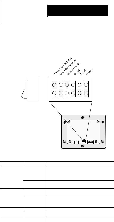
The 6 position DIP switch allows you to enable or disable certain functions. The DIP switch is accessed by removing the access cover on the back (access cover is shipped in the hardware bag on new units).
Figure 2.4
DIP Switch
Side View
1 |
2 |
3 |
4 |
5 |
6 |
ON =
OPEN
|
|
|
|
|
|
|
|
Back of DTAM Micro |
|||
Switch Position |
Setting |
Function |
|||
|
|
ON position allows the transfer of application files between |
|||
|
ON |
the DTAM Micro and personal computer running DPS. All |
|||
|
communication between the DTAM Micro and controller are |
||||
1 |
|
||||
|
disabled. Keypad entry is also disabled. |
||||
|
OFF |
OFF enables communication between the DTAM Micro and |
|||
|
controller. |
||||
|
|
||||
|
ON |
ON enables the master code. Enabling the master code |
|||
|
allows any security code to be accessed or modified. |
||||
|
|
||||
2 |
|
OFF disables the master code. Disabling the master code |
|||
|
OFF |
still allows access to a security screen or special functions |
|||
|
|
but does not allow security codes to be modified. |
|||
3 |
ON |
ON enables the Mode key on the front panel. |
|||
OFF |
OFF disables the Mode key on the front panel. |
||||
|
|||||
4, 5, 6 |
ON or OFF |
Reserved for future use. |
|||
DTAM Micro is reset each time this switch position is changed.
2–7
Chapter 2
DTAM Micro Overview
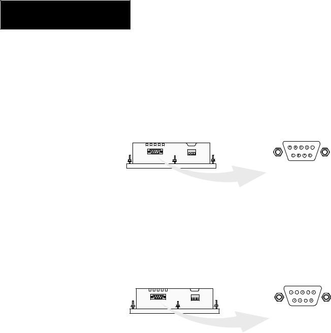
Communications Port
All communications are through a 9 pin connector on the bottom of the DTAM Micro. The connector is either an RS-232 port or RS-485 port depending upon the version catalog number.
Figure 2.5
Communications Port
DTAM Micro |
9 Pin Female |
|
(Bottom View) |
||
PIN # |
Signal Name |
|
1 |
Data Out – |
|
2 |
Data Out + |
|
3 |
Data In - |
|
4 |
Data In + |
|
5 |
Signal Ground |
|
6 |
Transmit Enable |
|
7 |
Not Used |
|
8 |
Signal Ground |
|
9 |
Shield |
|
RS-485 Version |
|
|
(Catalog No. 2707-M485P3) |
|
|
DTAM Micro |
9 Pin Female |
|
(Bottom View) |
||
|
||
PIN # Signal Name |
||
1 |
Not Used |
|
2 |
Receive Data (RD) |
|
3 |
Transmit Data (TD) |
|
4 |
Not Used |
|
5 |
Signal Ground |
|
6 |
Not Used |
|
7 |
Not Used |
|
8 |
Not Used |
|
9 |
Shield |
|
RS-232 Version
(Catalog No. 2707-M232P3)
2–8
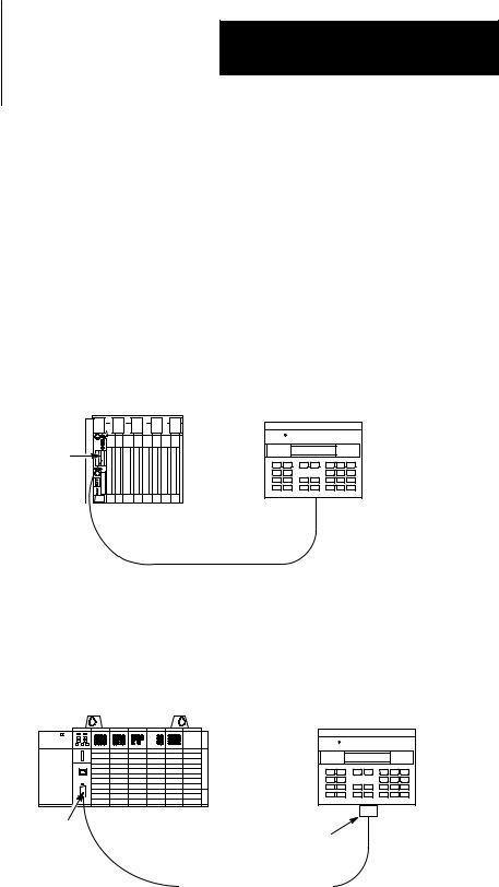
RS-232 Communications
Chapter 2
DTAM Micro Overview
RS-232 Version (Catalog No. 2707-M232P3)
The RS-232 port allows point-to-point communications with:
•PLC-5 Channel 0 (configured as RS-232 port, DF1 protocol)
•SLC 5/03, 5/04, 5/05 RS-232 port (DH485 protocol)
•MicroLogix 1000
Figure 2.6
Typical RS-232 Communications
DTAM Micro to PLC-5 Channel 0
PLC-5 |
Channel 0 |
DTAM Micro
DTAM Micro
RS-232 Port
RS-232
Cable (Catalog No. 2707-NC3)
DTAM Micro to SLC 5/03, 5/04, 5/05
SLC 5/03 |
DTAM Micro |
|
DTAM Micro
RS-232 Port
Channel 0 |
Gender |
|
Adapter |
|
RS-232 |
|
Cable (Catalog No. 1747-CP3) |
|
Gender Adapter Required |
2–9

Chapter 2
DTAM Micro Overview
RS-485 Communications
RS-485 Version (Catalog No. 2707-M485P3)
The RS-485 port allows point-to-point and multi-drop communications with:
•PLC-5 Channel 0 (configured as RS-422 port, DF1 protocol)
•SLC 500 DH-485 port
•MicroLogix 1000 using the AIC+ Interface
Figure 2.7
Typical RS-485 Communications
DTAM Micro to Single SLC |
DTAM Micro to PLC-5 Channel 0 |
DTAM Micro |
PLC-5 |
DTAM Micro |
SLC |
|
|
|
Channel 0 |
|
DTAM Micro |
|
DTAM Micro |
RS-485 Port |
|
RS-485 Port |
RS-485
Cable (Catalog No. 2707-NC1)
RS-422
Cable (Catalog No. 2707-NC4)
DTAM Micro to DH-485 Network
DTAM Plus |
SLC |
DTAM Micro |
DTAM Micro
RS-485 Port
DH-485
RS-485
Cable
(Catalog No. 2707-NC1)
Link Coupler |
Link Coupler |
Interface
Converter
Programming Terminal |
RS-232 to RS-422 |
|
Link Coupler |
||
|
2–10
Programming
the DTAM Micro
Chapter 2
DTAM Micro Overview
The DTAM Micro is programmed off-line using a personal computer running DTAM Plus Programming Software (DPS). Operating system upgrades are also transferred using a personal computer.
DTAM Programming Software (DPS)
Use DPS software (Catalog No. 2707-NP, Series H or later) to create application screens for both the DTAM Micro and DTAM Plus Operator Terminals. For a description of DPS, refer to the Programming Manual (Publication No. 2707-801).
Upload/Download Connections
For programming and configuration, the DTAM Micro is connected to your computer’s RS-232 port. If you have a DTAM Micro RS-485 version, an RS-232 to RS-422 converter cable (Catalog No. 2707-NC5) is required. The RS-485 version of the DTAM Micro is compatible with the converter cable’s RS-422 output.
Upload/Download Connection to RS-232 DTAM Micro
DTAM Micro
Programming Terminal |
RS-232 Port |
|
Cable
(Catalog No. 2707-NC2)
Upload/Download Connection to RS-485 DTAM Micro
DTAM Micro
RS-232 to RS-422
Interface
Converter
Built Into Cable
Programming Terminal
RS-485 Port
Cable
(Catalog No. 2707-NC5)
2–11

Chapter 2
DTAM Micro Overview
Default Settings
The DTAM Micro is preset at the factory with the following defaults:
Operating System
The DTAM Micro is provided with a default application file:
•RS-485 version has DH-485 operating system file
•RS-232 version has PLC-5 DF1 operating system file
The application file displays a screen with the message:
Bul 2707 DTAM Micro
No Program loaded
DIP Switch Settings
The DTAM Micro is shipped with the following DIP Switch settings:
DIP Switch |
Default |
Function |
|
Position |
Setting |
||
|
|||
|
|
|
|
1 |
ON |
Upload/Download Enabled |
|
|
|
|
|
2 |
OFF |
Master Security Disabled |
|
|
|
|
|
3 |
ON |
Mode Key enabled |
|
|
|
|
|
4 |
OFF |
Not Used |
|
|
|
|
|
5 |
OFF |
Not Used |
|
|
|
|
|
6 |
OFF |
Not Used |
Operating Parameters
The following operating functions can be set using the DTAM Micro menu functions. Refer to Chapter 3.
Function |
Parameter |
Default Value |
||
|
|
|||
RS-485 Version |
RS-232 Version |
|||
|
|
|||
|
|
|
|
|
|
Baud |
19200 |
2400 |
|
|
|
|
|
|
C-Port |
Data Bits |
8 |
8 |
|
|
|
|
|
|
|
Parity |
Even |
None |
|
|
|
|
|
|
|
DTAM Micro Node |
00 |
N/A |
|
|
|
|
|
|
Special |
Max. Node |
02 |
N/A |
|
|
|
|
|
|
|
Controller Node |
01 |
N/A |
|
|
|
|
|
|
|
Simulate |
Off |
Off |
|
|
|
|
|
|
Other |
Master Code |
00000000 |
00000000 |
|
|
|
|
|
|
|
Scale |
On |
On |
|
|
|
|
|
|
2–12

Product Options
Product Accessories
Chapter 2
DTAM Micro Overview
The table below lists the options available for the DTAM Micro.
Table 2.A
DTAM Micro Base Items
Item |
Catalog No. |
Description |
|
|
|
DTAM Micro |
2707-M485P3 |
DTAM Micro with RS-485 Communications Port |
|
|
|
DTAM Micro |
2707-M232P3 |
DTAM Micro with RS-232 Communications Port |
|
|
|
Programming |
2707-NP |
Use to create application screens for the DTAM Micro on |
Software |
(Series H or later) |
a personal computer. Software allows completed applica- |
|
|
tions to be transferred between the DTAM Micro and a per- |
|
|
sonal computer. |
The following accessories are available for the DTAM Micro.
Table 2.B
Accessories
Item |
Catalog No. |
Description |
|
|
|
|
|
|
|
RS-485 communication cable connects DTAM Micro to an |
|
DH-485 Network |
|
SLC network. Cable has 9-pin male connector for the |
|
2707-NC1 |
communication port on the DTAM Micro and an 8-pin RJ |
||
Interface Cable |
|||
|
connector for the communication port on the SLC or Link |
||
|
|
||
|
|
Coupler (Catalog No. 1747-AIC). |
|
|
|
|
|
RS-232 |
|
RS-232 cable connects DTAM Micro (RS-232 version) |
|
|
and a personal computer. Use to upload or download |
||
Upload/Download |
2707-NC2 |
||
applications with a personal computer running DPS |
|||
Cable |
|
||
|
software (Catalog No. 2707-NP, Series H or later). |
||
|
|
||
|
|
|
|
RS-232 |
2707-NC3 |
RS-232 cable connects DTAM Micro to Channel 0 Port of |
|
Communications Cable |
a PLC-5. |
||
|
|||
|
|
|
|
RS-232 |
1747-CP3 |
RS-232 cable connects DTAM Micro to Channel 0 Port |
|
Communications Cable |
|
(configured for RS-232) of an SLC 5/03, 5/04, 5/05. |
|
RS-422 |
2707-NC4 |
RS-422 cable connects DTAM Micro to Channel 0 Port |
|
Communications Cable |
(configured for RS-422) of a PLC-5. |
||
|
|||
|
|
For use with RS-485 version of the DTAM Micro. |
|
RS-485 |
|
Transfers files between RS-485 port of the DTAM Micro |
|
|
and the personal computer’s RS-232 port. Cable |
||
Upload/Download |
2707-NC5 |
converts RS-232 signals to RS-422 signals for the DTAM |
|
Cable |
|
Micro. Cable has a 25-pin male connector for the |
|
|
|
computer port and a 9 pin male connector for the port on |
|
|
|
the DTAM Micro. |
|
|
|
|
|
RS-232 |
2707-NC10 |
RS-232 cable connects DTAM Micro to a MicroLogix 1000 |
|
Communications Cable |
|||
|
|
||
|
|
|
|
120V AC to DC Adapter |
1747-NP1 |
Provides 18 to 30 VDC output for the DTAM Micro. |
|
Operates on 120 VAC input line voltage. |
|||
|
|
||
|
|
|
|
240V AC to DC Adapter |
1747-NP2 |
Provides 18 to 30 VDC output for the DTAM Micro. |
|
Operates on 240 VAC input line voltage. |
|||
|
|
||
|
|
|
|
A 9-pin male to female gender adapter is required. |
|||
2–13

Chapter 2
DTAM Micro Overview
2–14

Chapter 3
Initial Setup and Mode Menu
Objectives
This chapter describes how to apply power to and then configure the DTAM Micro using the menu keys. Instructions on how to use the Simulate mode to run an application are provided. This chapter contains the following sections:
Section |
Page |
|
|
Apply Power |
3–2 |
|
|
Powerup Sequence |
3–3 |
|
|
Mode Menu |
3–4 |
|
|
Resetting the DTAM Micro |
3–5 |
|
|
Setting Communication Parameters Manually |
3–6 |
|
|
Special Functions for Controller Operations |
3–7 |
|
|
Entering a New Master Security Code |
3–8 |
|
|
Enabling / Disabling Scaling |
3–9 |
|
|
Using the Simulate Mode |
3–10 |
|
|
Test Functions |
3–11 |
3–1
Chapter 3
Initial Setup and Mode Main
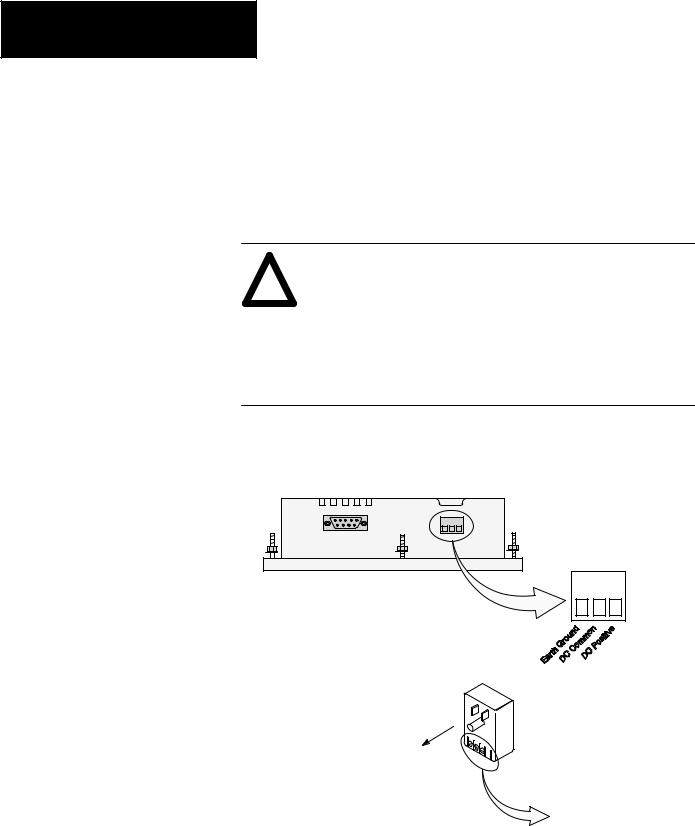
Apply Power |
This section describes power connections for initial desktop setup and |
|
programming. Refer to Chapter 6 for installation wiring instructions. |
|
The DTAM Micro is intended for 24 VDC systems. If 24 VDC is not |
|
directly available, you can use the AC to DC Adapters: Catalog No. |
|
1747-NP1 for 120 VAC or Catalog No. 1747-NP2 for 240 VAC power. |
ATTENTION: Verify that the power is disconnected from the
!result in electrical shock.
Make sure that the supply voltage to the DTAM Micro is 18 to 30 volts DC. The incorrect voltage may damage the DTAM Micro.
Do not overtighten the power connector screw terminals. Overtightening the terminals may damage the DTAM Micro.
1.Connect the DC positive, DC common, and ground lines as shown below.
Verify the connections by checking the DC power supply labels on the AC to DC Adapter (if used) and DTAM Micro.power source before wiring. Failure to disconnect power may
DTAM Micro
Optional AC to DC Adapter
Catalog No. 1747-NP1, -NP2
To 120VAC (Catalog No. 1747-NP1)
To 240VAC (Catalog No. 1747-NP2)
To DTAM Micro. Check DC power labels before making connections.
2.Apply power to the DTAM Micro by plugging the AC to DC Adapter into the proper power source (check Adapter label to verify voltage).
The DTAM Micro performs a powerup sequence.
3–2
Powerup Sequence
Chapter 3
Initial Setup and Mode Menu
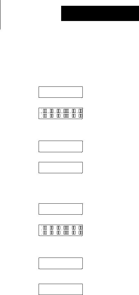
The powerup sequence is automatic, you do not have to respond to
the screens. The sequence depends upon DIP switch position #1 (upload / download enable). The DTAM Micro is shipped with this switch On.
Powerup Sequence (DIP Switch #1 On)
1.The DTAM Micro verifies the system memory checksum, program checksum, and system RAM. After the test is completed, the result is displayed with the current DIP switch settings.
Memory Check: pass
DIP Switch: 101000
2.The display is tested, every pixel of the display is turned on
If all of the pixels do not turn on, the display may be defective.
3.DTAM Micro information appears indicating the microprocessor core firmware version and communication port (RS-232 or RS-485).
Operator Interface
Core: 3.00 RS-232
4. The DTAM Micro waits for an application download.
Programming Mode
Waiting Up/Download
Powerup Sequence (DIP Switch #1 Off)
1.The DTAM Micro verifies the system memory checksum, program checksum, and system RAM. After the test is completed, the result is displayed with the current DIP switch settings.
Memory Check: pass
DIP Switch: 101000
2.The display is tested, every pixel of the display is turned on.
If all of the pixels do not turn on, the display may be defective.
3.Operating system information appears indicating the firmware release number and protocol being used (PLC5-DF1 or AB DH-485).
DTAM Micro (c) 1994
FRN 2.20 PLC5-DF1
4.The first application screen displays. If the DTAM Micro is being powered up the first time you will see:
Bul. 2707 DTAM Micro
No Program Loaded
3–3
Chapter 3
Initial Setup and Mode Main
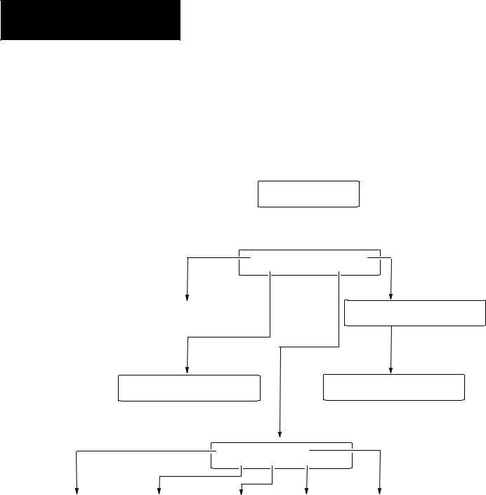
Mode Menu
Sets Master
Security Code
Access the Mode Menu by pressing the [MODE] key. All other functions are halted when the menu is displayed.
Note: DIP switch SW-3 must be in the On position or the [MODE] key will not function.
The Mode Menu provides access to four functions:
1 Reset |
3 Special |
2 Com-Port |
4 Other |
Select a menu item by pressing the corresponding numeric key [1] ! [4]. The menu structure is shown below:
|
|
1 Reset |
3 Special |
|
|
|
||||
|
|
|
|
|||||||
|
|
|
|
|||||||
|
|
2 Com-Port |
4 Other |
|
||||||
|
|
|
|
|
|
|
SLC or 50X Address |
|
||
Resets the DTAM Micro |
|
|
|
|||||||
|
|
|
|
|
|
|
1 = Edit Addr |
0 = Bypass |
||
(Only with DH485 Operating System)
1 Baud Rate |
3 Parity |
1 P-A/D |
3 Mem Xfer |
2 Data Bits |
4 Exit |
2 Mode |
4 Clr Fault |
Configures DTAM Micro |
|
|
Special |
|
Communications Port |
|
|
Controller Operations |
|
|
1 Master |
3 Simulate |
|
|
|
2 Scale |
4 Test |
5 Ex |
|
Enables / Disables |
Performs |
|
Exits to |
Simulates Controller |
Scaling |
Functional Tests |
Mode Menu |
Communications |
|
DIP switch position 2 must be On (master code enable).
3–4

Resetting the DTAM Micro
Chapter 3
Initial Setup and Mode Menu
Use the reset function to reset the DTAM Micro after DIP switch changes or a configuration change using the Mode Menu.
To reset the DTAM Micro:
1. From the Mode Menu select 1 Reset.
1 Reset |
3 Special |
2 Com-Port |
4 Other |
You are prompted:
1 = Reset DTAM Micro
0 = Abort
2.Press [1] on the keypad to initiate the reset.
The DTAM Micro resets. This has the same effect as turning the power off and on. The DTAM Micro performs the self diagnostic tests and powerup displays as described in the previous section.
3–5

Chapter 3
Initial Setup and Mode Main
Setting Communication
Parameters Manually
The Com-Port option on the Mode Menu lets you to manually adjust the communication port parameters. Normally these parameters are set automatically from the programming software when an application is downloaded.
Select Com-Port from the Mode Menu.
1 Reset |
3 Special |
2 Com-Port |
4 Other |
This menu displays:
1 |
Baud Rate |
3 Parity |
2 |
Data Bits |
4 Exit |
Select an item by pressing the corresponding numeric key [1] ! [4].
Baud Rate
Selecting Baud Rate displays the current baud rate.
Baud Rate |
19200 |
“Next” to change
Press [Next] to select a new rate: 300, 1200, 2400, 4800, 9600, 19200, 38400. DH-485 communications with an SLC or network cannot be set at 300 Baud.
Data Bits
Selecting Data Bits displays the current setting.
Data Bits |
7 |
“Next” to change
Press [Next] to select either 7 or 8 bits.
Parity
Selecting Parity displays the current setting.
Parity |
Even |
“Next” to change
Press [Next] to select Even, Odd, or No parity.
3–6
Loading...