


 Loading...
User Manual
Micro800 Plug-in Modules
Catalog Numbers 2080-IQ4, 2080-IQ4OB4, 2080-IQ4OV4, 2080-OB4, 2080-OV4, 2080-OW4I, 2080-IF2, 2080IF4, 2080-OF2, 2080-TC2, 2080-RTD2, 2080-MEMBAK-RTC, 2080-TRIMPOT6, 2080-SERIALISOL, 2080-DNET20, 2080-MOT-HSC

Important User Information
Solid-state equipment has operational characteristics differing from those of electromechanical equipment. Safety Guidelines for the Application, Installation and Maintenance of Solid State Controls (publication SGI-1.1 available from your local Rockwell Automation sales office or online at http://www.rockwellautomation.com/literature/) describes some important differences between solid-state equipment and hard-wired electromechanical devices. Because of this difference, and also because of the wide variety of uses for solid-state equipment, all persons responsible for applying this equipment must satisfy themselves that each intended application of this equipment is acceptable.
In no event will Rockwell Automation, Inc. be responsible or liable for indirect or consequential damages resulting from the use or application of this equipment.
The examples and diagrams in this manual are included solely for illustrative purposes. Because of the many variables and requirements associated with any particular installation, Rockwell Automation, Inc. cannot assume responsibility or liability for actual use based on the examples and diagrams.
No patent liability is assumed by Rockwell Automation, Inc. with respect to use of information, circuits, equipment, or software described in this manual.
Reproduction of the contents of this manual, in whole or in part, without written permission of Rockwell Automation, Inc., is prohibited.
Throughout this manual, when necessary, we use notes to make you aware of safety considerations.
WARNING: Identifies information about practices or circumstances that can cause an explosion in a hazardous environment, which may lead to personal injury or death, property damage, or economic loss.
ATTENTION: Identifies information about practices or circumstances that can lead to personal injury or death, property damage, or economic loss. Attentions help you identify a hazard, avoid a hazard, and recognize the consequence
SHOCK HAZARD: Labels may be on or inside the equipment, for example, a drive or motor, to alert people that dangerous voltage may be present.
BURN HAZARD: Labels may be on or inside the equipment, for example, a drive or motor, to alert people that surfaces may reach dangerous temperatures.
IMPORTANT Identifies information that is critical for successful application and understanding of the product.
Allen-Bradley, Rockwell Software, Rockwell Automation, Micro800, Micro820, Micro830, Micro850, Kinetix, PowerFlex, CompactBlock, KwikLink, Connected Components Workbench, and TechConnect are trademarks of Rockwell Automation, Inc.
Trademarks not belonging to Rockwell Automation are property of their respective companies.

Preface
Who Should Use this Manual
Purpose of this Manual
Read this preface to familiarize yourself with the rest of the manual. It provides information concerning:
•who should use this manual
•the purpose of this manual
•related documentation
•supporting information for Micro800™ plug-in modules and accessories
Use this manual if you are responsible for designing, installing, programming, or troubleshooting control systems that use Micro800 controllers.
You should have a basic understanding of electrical circuitry and familiarity with relay logic. If you do not, obtain the proper training before using this product.
This manual is a reference guide for Micro800 controllers, plug-in modules and accessories. It describes the procedures you use to install, wire, and troubleshoot your controller. This manual:
•explains how to install and wire your plug-ins
•gives you an overview of the Micro800 plug-in modules and accessories
Additional Resources
Refer to the additional resources for more information on other element of the Micro800 system.
These documents contain additional information concerning related Rockwell Automation products.
Resource |
Description |
|
|
Micro800 Programmable Controller External AC Power Supply |
Information on mounting and wiring the optional external power supply. |
Installation Instructions 2080-IN001 |
|
|
|
Micro830 Programmable Controllers Installation Instructions |
Information on mounting and wiring the Micro830 10-point controllers. |
2080-IN002 |
|
|
|
Micro830 Programmable Controllers Installation Instructions |
Information on mounting and wiring the Micro830 16-point controllers. |
2080-IN003 |
|
|
|
Micro830 Programmable Controllers Installation Instructions |
Information on mounting and wiring the Micro830 24-point controllers. |
2080-IN004 |
|
|
|
Micro830 Programmable Controllers Installation Instructions |
Information on mounting and wiring the Micro830 48-point controllers. |
2080-IN005 |
|
|
|
Micro850 Programmable Controllers Installation Instructions |
Information on mounting and wiring the Micro850 24-point controllers. |
2080-IN007 |
|
|
|
Micro850 Programmable Controllers Installation Instructions |
Information on mounting and wiring the Micro850 48-point controllers. |
2080-IN008 |
|
|
|
Micro820 Programmable Controllers Installation Instructions |
Information on mounting and wiring the Micro820 20-point controllers. |
2080-IN009 |
|
|
|
Micro800 Remote LCD Installation Instructions 2080-IN010 |
Information on mounting and wiring the Micro800 Remote LCD module. |
|
|
Rockwell Automation Publication 2080-UM004B-EN-E - December 2013 |
iii |

Preface
Resource |
Description |
|
|
Micro800 RS232/485 Isolated Serial Port Plug-in Module Wiring |
Information on mounting and wiring the Micro800 RS232/485 isolated serial |
Diagrams 2080-WD002 |
port plug-in module. |
|
|
Micro800 Non-isolated Unipolar Analog Input Plug-in Module Wiring |
Information on mounting and wiring the Micro800 non-isolated unipolar analog |
Diagrams 2080-WD003 |
input plug-in module. |
|
|
Micro800 Non-isolated Unipolar Analog Output Plug-in Module Wiring |
Information on mounting and wiring the Micro800 non-isolated unipolar analog |
Diagrams 2080-WD004 |
output plug-in module. |
|
|
Micro800 Non-isolated RTD Plug-in Module Wiring Diagrams |
Information on mounting and wiring the Micro800 non-isolated RTD plug-in |
2080-WD005 |
module. |
|
|
Micro800 Non-isolated Thermocouple Plug-in Module Wiring Diagrams |
Information on mounting and wiring the Micro800 non-isolated thermocouple |
2080-WD006 |
plug-in module. |
|
|
Micro800 Memory Backup and High Accuracy RTC Plug-In Module |
Information on mounting and wiring the Micro800 memory backup and high |
Wiring Diagrams 2080-WD007 |
accuracy RTC plug-in module. |
|
|
Micro800 6-Channel Trimpot Analog Input Plug-In Module Wiring |
Information on mounting and wiring the Micro800 6-channel trimpot analog |
Diagrams 2080-WD008 |
input plug-in module. |
|
|
Micro800 Digital Relay Output Plug-in Module Wiring Diagrams |
Information on mounting and wiring the Micro800 digital relay output plug-in |
2080-WD010 |
module. |
|
|
Micro800 Digital Input, Output, and Combination Plug-in Modules |
Information on mounting and wiring the Micro800 digital input, output, and |
Wiring Diagrams 2080-WD011 |
combination plug-in module. |
|
|
Micro800 High-speed Counter Plug-in Module 2080-WD012 |
Specifications and information on wiring the Micro800 high-speed counter |
|
plug-in module. |
|
|
Micro800 DeviceNet Plug-in Module 2080-WD013 |
Specifications and information on wiring the Micro800 DeviceNet plug-in |
|
module. |
|
|
Micro820 Programmable Controller User Manual, |
Information on features, installation, wiring and usage of the Micro820 |
publication 2080-UM005 |
controllers. |
|
|
Micro830 and Micro850 Programmable Controller User Manual, |
Information on features, installation, wiring and usage of the Micro830 and |
publication 2080-UM002 |
Micro850 controllers. |
|
|
Industrial Automation Wiring and Grounding Guidelines, publication |
Provides general guidelines for installing a Rockwell Automation industrial |
1770-4.1 |
system. |
|
|
Product Certifications website, http://www.rockwellautomation.com/ |
Provides declarations of conformity, certificates, and other certification details. |
products/certification/ |
|
|
|
Application Considerations for Solid-State Controls SGI-1.1 |
A description of important differences between solid-state programmable |
|
controller products and hard-wired electromechanical devices. |
|
|
National Electrical Code - Published by the National Fire Protection |
An article on wire sizes and types for grounding electrical equipment. |
Association of Boston, MA. |
|
|
|
Allen-Bradley Industrial Automation Glossary AG-7.1 |
A glossary of industrial automation terms and abbreviations. |
|
|
You can view or download publications at http://www.rockwellautomation.com/ literature/. To order paper copies of technical documentation, contact your local Rockwell Automation distributor or sales representative.
You can download the latest version of Connected Components Workbench for your Micro800 at the URL below.
http://ab.rockwellautomation.com/Programmable-Controllers/Connected-
Components-Workbench-Software.
iv |
Rockwell Automation Publication 2080-UM004B-EN-E - December 2013 |

|
Table of Contents |
|
Preface |
Who Should Use this Manual . . . . . . . . . . . . . . . . . . . . . . . . . . . . . . . . . . . . . . |
iii |
|
Purpose of this Manual . . . . . . . . . . . . . . . . . . . . . . . . . . . . . . . . . . . . . . . . . . . . |
iii |
|
Additional Resources . . . . . . . . . . . . . . . . . . . . . . . . . . . . . . . . . . . . . . . . . . . . . . |
iii |
|
Chapter 1 |
|
Micro800 Plug-in Modules |
Digital Plug-ins . . . . . . . . . . . . . . . . . . . . . . . . . . . . . . . . . . . . . . . . . . . . . . . . . . . |
. 2 |
|
12/24V Digital Plug-ins — 2080-IQ4, 2080-IQ4OB4, |
|
|
2080-IQ4OV4, 2080-OB4, 2080-OV4. . . . . . . . . . . . . . . . . . . . . . . . . . |
. 2 |
|
AC/DC Relay Output Module — 2080-OW4I. . . . . . . . . . . . . . . . . . |
. 3 |
|
Analog Plug-ins . . . . . . . . . . . . . . . . . . . . . . . . . . . . . . . . . . . . . . . . . . . . . . . . . . . |
. 3 |
|
Non-isolated Unipolar Analog Input and Output — 2080-IF2, |
|
|
2080-IF4, 2080-OF2 . . . . . . . . . . . . . . . . . . . . . . . . . . . . . . . . . . . . . . . . . . |
. 3 |
|
Specialty Plug-ins . . . . . . . . . . . . . . . . . . . . . . . . . . . . . . . . . . . . . . . . . . . . . . . . . |
. 3 |
|
Non-isolated Thermocouple and RTD — 2080-TC2 and |
|
|
2080-RTD2 . . . . . . . . . . . . . . . . . . . . . . . . . . . . . . . . . . . . . . . . . . . . . . . . . . |
. 3 |
|
Memory Backup and High Accuracy RTC — |
|
|
2080-MEMBAK-RTC . . . . . . . . . . . . . . . . . . . . . . . . . . . . . . . . . . . . . . . . |
. 3 |
|
Six-channel Trimpot — 2080-TRIMPOT6 . . . . . . . . . . . . . . . . . . . . . |
. 4 |
|
High Speed Counter — 2080-MOT-HSC . . . . . . . . . . . . . . . . . . . . . . |
. 4 |
|
Communication Plug-ins . . . . . . . . . . . . . . . . . . . . . . . . . . . . . . . . . . . . . . . . . . |
. 4 |
|
RS232/RS485 Isolated Serial Port — 2080-SERIALISOL . . . . . . . . |
. 4 |
|
DeviceNet Scanner — 2080-DNET20 . . . . . . . . . . . . . . . . . . . . . . . . . . |
. 5 |
|
Chapter 2 |
|
Install and Wire Your Module |
Hardware Features . . . . . . . . . . . . . . . . . . . . . . . . . . . . . . . . . . . . . . . . . . . . . . . . |
. 7 |
|
Insert Module into Controller. . . . . . . . . . . . . . . . . . . . . . . . . . . . . . . . . . . . . . |
. 7 |
|
Wiring . . . . . . . . . . . . . . . . . . . . . . . . . . . . . . . . . . . . . . . . . . . . . . . . . . . . . . . . . . . |
. 8 |
|
Wiring Considerations and Applications for 2080-TC2 . . . . . . . . . . . . . |
12 |
|
Type of CJC Sensor . . . . . . . . . . . . . . . . . . . . . . . . . . . . . . . . . . . . . . . . . . |
12 |
|
Wire the CJC Thermistor on the 2080-TC2 Module. . . . . . . . . . . . |
12 |
|
Wiring Considerations and Applications for 2080-RTD2 . . . . . . . . . . . |
13 |
|
Two-wire and Three-Wire Wiring . . . . . . . . . . . . . . . . . . . . . . . . . . . . |
13 |
|
Wire the RTD Sensors. . . . . . . . . . . . . . . . . . . . . . . . . . . . . . . . . . . . . . . . |
13 |
|
Wire the RTD Module and RTD Sensor in the Field . . . . . . . . . . . . |
14 |
|
Wiring Applications for 2080-MOT-HSC . . . . . . . . . . . . . . . . . . . . . . . . . |
16 |
Non-isolated Thermocouple and RTD Plug-in Modules – 2080-TC2 and 2080-RTD2
Chapter 3
Thermocouple Module . . . . . . . . . . . . . . . . . . . . . . . . . . . . . . . . . . . . . . . . . . . 19
Thermocouple Sensor Types and Ranges . . . . . . . . . . . . . . . . . . . . . . . 19
RTD Module . . . . . . . . . . . . . . . . . . . . . . . . . . . . . . . . . . . . . . . . . . . . . . . . . . . . 20
RTD Sensor Types and Ranges . . . . . . . . . . . . . . . . . . . . . . . . . . . . . . . . 20
Connected Components Workbench Global Variables
Data Maps. . . . . . . . . . . . . . . . . . . . . . . . . . . . . . . . . . . . . . . . . . . . . . . . . . . . . . . 22
Temperature Conversion – Data to Degree Celsius (°C) . . . . . . . . . 23
Rockwell Automation Publication 2080-UM004AB-EN-E - December 2013 |
v |

Table of Contents
High Speed Counter –
2080-MOT-HSC
DeviceNet Plug-in –
2080-DNET20
Specifications
Quickstart
Chapter 4
Overview . . . . . . . . . . . . . . . . . . . . . . . . . . . . . . . . . . . . . . . . . . . . . . . . . . . . . . . . 25
Counter Specifications. . . . . . . . . . . . . . . . . . . . . . . . . . . . . . . . . . . . . . . . . . . . 25
Number of Counters: 1 to 2 . . . . . . . . . . . . . . . . . . . . . . . . . . . . . . . . . . . 26 Up Counter . . . . . . . . . . . . . . . . . . . . . . . . . . . . . . . . . . . . . . . . . . . . . . . . . . 27
Counter with External Direction. . . . . . . . . . . . . . . . . . . . . . . . . . . . . . . 27
Understanding Rates. . . . . . . . . . . . . . . . . . . . . . . . . . . . . . . . . . . . . . . . . . 33 User Defined Function Blocks. . . . . . . . . . . . . . . . . . . . . . . . . . . . . . . . . . . . . 35
RA_HSCPlugIn. . . . . . . . . . . . . . . . . . . . . . . . . . . . . . . . . . . . . . . . . . . . . . 35
Use the 2080-MOT-HSC Module . . . . . . . . . . . . . . . . . . . . . . . . . . . . . 38
Chapter 5
Overview . . . . . . . . . . . . . . . . . . . . . . . . . . . . . . . . . . . . . . . . . . . . . . . . . . . . . . . . 39
Status Indicators . . . . . . . . . . . . . . . . . . . . . . . . . . . . . . . . . . . . . . . . . . . . . . . . . 39
Network Configuration. . . . . . . . . . . . . . . . . . . . . . . . . . . . . . . . . . . . . . . . . . . 40
Network Wiring. . . . . . . . . . . . . . . . . . . . . . . . . . . . . . . . . . . . . . . . . . . . . . 40
DeviceNet Switches. . . . . . . . . . . . . . . . . . . . . . . . . . . . . . . . . . . . . . . . . . . 41
Power Supply. . . . . . . . . . . . . . . . . . . . . . . . . . . . . . . . . . . . . . . . . . . . . . . . . 42
User Defined Function Blocks. . . . . . . . . . . . . . . . . . . . . . . . . . . . . . . . . . . . . 45
RA_DNET_MASTER . . . . . . . . . . . . . . . . . . . . . . . . . . . . . . . . . . . . . . . 45
RA_DNET_NODE_STATUS. . . . . . . . . . . . . . . . . . . . . . . . . . . . . . . . 46
RA_DNET_LDX_DISCRETE . . . . . . . . . . . . . . . . . . . . . . . . . . . . . . . 47
RA_DNET_LDX_ANALOG . . . . . . . . . . . . . . . . . . . . . . . . . . . . . . . . 48
RA_DNET_LDX_TC_RTD . . . . . . . . . . . . . . . . . . . . . . . . . . . . . . . . . 49
RA_PF_DNET_STANDARD . . . . . . . . . . . . . . . . . . . . . . . . . . . . . . . . 50
RA_PF_DNET_MULTIDRIVE . . . . . . . . . . . . . . . . . . . . . . . . . . . . . . 51
RA_DNET_OVERLOAD. . . . . . . . . . . . . . . . . . . . . . . . . . . . . . . . . . . . 53
RA_DNET_GENERIC . . . . . . . . . . . . . . . . . . . . . . . . . . . . . . . . . . . . . . 53
Error Codes. . . . . . . . . . . . . . . . . . . . . . . . . . . . . . . . . . . . . . . . . . . . . . . . . . . . . . 56
Use the 2080-DNET20 Plug-in. . . . . . . . . . . . . . . . . . . . . . . . . . . . . . . . 56
Appendix A
Digital Plug-in Modules. . . . . . . . . . . . . . . . . . . . . . . . . . . . . . . . . . . . . . . . . . . 57
Analog Plug-in Modules . . . . . . . . . . . . . . . . . . . . . . . . . . . . . . . . . . . . . . . . . . 62
Specialty Plug-in Modules . . . . . . . . . . . . . . . . . . . . . . . . . . . . . . . . . . . . . . . . . 64
Communication Plug-in Modules . . . . . . . . . . . . . . . . . . . . . . . . . . . . . . . . . 71
Appendix B
Add and Configure Plug-ins in Connected Components Workbench. 77
Quickstart Project for 2080-DNET20 Plug-in . . . . . . . . . . . . . . . . . . . . . . 79 Setup and Wiring . . . . . . . . . . . . . . . . . . . . . . . . . . . . . . . . . . . . . . . . . . . . . 80 Configuration . . . . . . . . . . . . . . . . . . . . . . . . . . . . . . . . . . . . . . . . . . . . . . . . 82 Build and Download . . . . . . . . . . . . . . . . . . . . . . . . . . . . . . . . . . . . . . . . . . 83 Execute Program. . . . . . . . . . . . . . . . . . . . . . . . . . . . . . . . . . . . . . . . . . . . . . 83
vi |
Rockwell Automation Publication 2080-UM004AB-EN-E - December 2013 |

|
|
Chapter 2 |
|
Quickstart Projects for 2080-MOT-HSC Plug-in. . . . . . . . . . . . . . . |
. . . . 84 |
|
Setup and Wiring. . . . . . . . . . . . . . . . . . . . . . . . . . . . . . . . . . . . . . . . . |
. . . . 84 |
|
Configuration for UDFB 1: RA_HSCPlugIn . . . . . . . . . . . . . . . |
. . . 85 |
|
Build and Download. . . . . . . . . . . . . . . . . . . . . . . . . . . . . . . . . . . . . . . |
. . . 86 |
|
Execute the Function Block . . . . . . . . . . . . . . . . . . . . . . . . . . . . . . . . |
. . . 86 |
|
Configuration for UDFB 2: RA_EncoderFDBK . . . . . . . . . . . . |
. . . 87 |
|
Build and Download. . . . . . . . . . . . . . . . . . . . . . . . . . . . . . . . . . . . . . . |
. . . 88 |
|
Execute the Function Block . . . . . . . . . . . . . . . . . . . . . . . . . . . . . . . . |
. . . 89 |
|
Configuration for HSC UDFB 3: RA_ServoFDBK . . . . . . . . . . |
. . . 90 |
|
Build and Download. . . . . . . . . . . . . . . . . . . . . . . . . . . . . . . . . . . . . . . |
. . . 91 |
|
Execute the Function Block . . . . . . . . . . . . . . . . . . . . . . . . . . . . . . . . |
. . . 92 |
|
Appendix C |
|
Error Codes |
Troubleshooting . . . . . . . . . . . . . . . . . . . . . . . . . . . . . . . . . . . . . . . . . . . . . . |
. . . 95 |
|
Error Codes for Micro800 Plug-ins . . . . . . . . . . . . . . . . . . . . . . . . . . . . . |
. . . 95 |
|
Calling Rockwell Automation for Assistance . . . . . . . . . . . . . . . . . . . . |
. . . 96 |
|
Index |
|
Rockwell Automation Publication 2080-UM004AB-EN-E - December 2013 |
vii |

Table of Contents
Notes:
viii |
Rockwell Automation Publication 2080-UM004AB-EN-E - December 2013 |

Chapter 1
Micro800 Plug-in Modules
Plug-in modules enhance the functionality of a base unit controller. With these modules, you can:
•Extend the functionality of embedded I/O without increasing the footprint of your controller.
•Improve performance by adding additional processing power or capabilities.
•Add additional communication functionality.
Micro820, Micro830, and Micro850 support the following plug-in modules:
Micro800 Plug-in Modules
Module |
Type |
Description |
|
|
|
2080-IQ4 |
Digital |
4-point, 12/24V DC Sink/Source input |
|
|
|
2080-IQ4OB4 |
Digital |
8-point, Combo, 12/24V DC Sink/Source input |
|
|
12/24V DC Source output |
|
|
|
2080-IQ4OV4 |
Digital |
8-point, Combo, 12/24V DC Sink/Source input |
|
|
12/24V DC Sink output |
|
|
|
2080-OB4 |
Digital |
4-point, 12/24V DC Source output |
|
|
|
2080-OV4 |
Digital |
4-point, 12/24V DC Sink output |
|
|
|
2080-OW4I |
Digital |
4-point, AC/DC Relay output |
|
|
|
2080-IF2 |
Analog |
2-channel, Non-isolated unipolar voltage/current |
|
|
analog input |
|
|
|
2080-IF4 |
Analog |
4-channel, Non-isolated unipolar voltage/current |
|
|
analog input |
|
|
|
Rockwell Automation Publication 2080-UM004B-EN-E - December 2013 |
1 |
Chapter 1 Micro800 Plug-in Modules
Micro800 Plug-in Modules
Module |
Type |
Description |
|
|
|
2080-OF2 |
Analog |
2-channel, Non-isolated unipolar voltage/current |
|
|
analog output |
|
|
|
2080-TC2 |
Specialty |
2-channel, non-isolated thermocouple module |
|
|
|
2080-RTD2 |
Specialty |
2-channel, non-isolated RTD module |
|
|
|
2080-MEMBAK-RTC(1) |
Specialty |
Memory backup and high accuracy RTC |
2080-TRIMPOT6 |
Specialty |
6-channel trimpot analog input |
|
|
|
2080-MOT-HSC |
Specialty |
High speed counter |
|
|
|
2080-DNET20 |
Communication |
20-node DeviceNet scanner |
|
|
|
2080-SERIALISOL |
Communication |
RS232/485 isolated serial port |
|
|
|
(1) 2080-MEMBAK-RTC is not supported on Micro820 controllers.
Number of support for Micro800 plug-ins on the controllers are summarized in the following table.
Plug-in Slots on Micro800 Controllers
Controller |
Number of Plug-in Slots |
|
|
|
|
Micro810 |
0 |
|
|
|
|
Micro820 |
2 |
|
|
|
|
Micro830 |
2 |
(10/16 points) |
|
3 |
(24 points) |
|
5 |
(48 points) |
|
|
|
Micro850 |
3 |
(24 points) |
|
5 |
(48 points) |
|
|
|
ATTENTION: Removal and Insertion Under Power (RIUP) is not supported on all Micro800 plug-in modules, except on the 2080-MEMBAK-RTC module.
ATTENTION: Micro800 plug-in modules can be installed on any plug-in slot on the controller, except for the 2080-MEMBAK-RTC module which can only be installed on the leftmost plug-in slot.
Digital Plug-ins |
12/24V Digital Plug-ins — 2080-IQ4, 2080-IQ4OB4, 2080-IQ4OV4, |
|
2080-OB4, 2080-OV4 |
|
These digital plug-in modules provide transistor outputs for switching a variety |
|
of 12/24V DC voltages to field loads and for detecting 12/24V signals from field |
|
devices. |
2 |
Rockwell Automation Publication 2080-UM004B-EN-E - December 2013 |
|
Micro800 Plug-in Modules Chapter 1 |
|
|
|
AC/DC Relay Output Module — 2080-OW4I |
|
The 2080-OW4I is a 4-channel relay output and provides dry contact relay |
|
closure outputs for switching a variety of AC and DC voltages to field loads. |
Analog Plug-ins |
The following analog plug-ins are supported by most Micro800 controllers. |
|
Non-isolated Unipolar Analog Input and Output — 2080-IF2, |
|
2080-IF4, 2080-OF2 |
|
These plug-in modules add extra embedded non-isolated unipolar (0...10V, |
|
0...20 mA) analog I/O and offer 12-bit resolution. |
Specialty Plug-ins |
Non-isolated Thermocouple and RTD — 2080-TC2 and 2080-RTD2 |
|
These non-isolated plug-in modules help to make temperature control possible |
|
when used with PID (Proportional Integral Derivative). |
|
See Non-isolated Thermocouple and RTD Plug-in Modules – 2080-TC2 and |
|
2080-RTD2 on page 19 for more information. |
|
Memory Backup and High Accuracy RTC — 2080-MEMBAK-RTC |
|
This plug-in allows you to make a backup copy of the project in your controller, |
|
and adds precision real-time clock function without needing to calibrate or |
|
update periodically. |
|
It can also be used to clone/update Micro830 and Micro850 application code. |
|
However, it cannot be used as additional Run-Time Program or Data Storage for |
|
recipe and datalog. |
Rockwell Automation Publication 2080-UM004B-EN-E - December 2013 |
3 |
Chapter 1 Micro800 Plug-in Modules
Status Indicators
State |
Description |
|
|
Solid red (2 s) |
Startup cycle test in progress. |
|
|
Flashing red |
Back up in progress. |
|
|
Solid red (continuous) |
Battery low. |
|
|
Project Backup and Restore
The project can be backed up and restored using Connected Components
Workbench software.
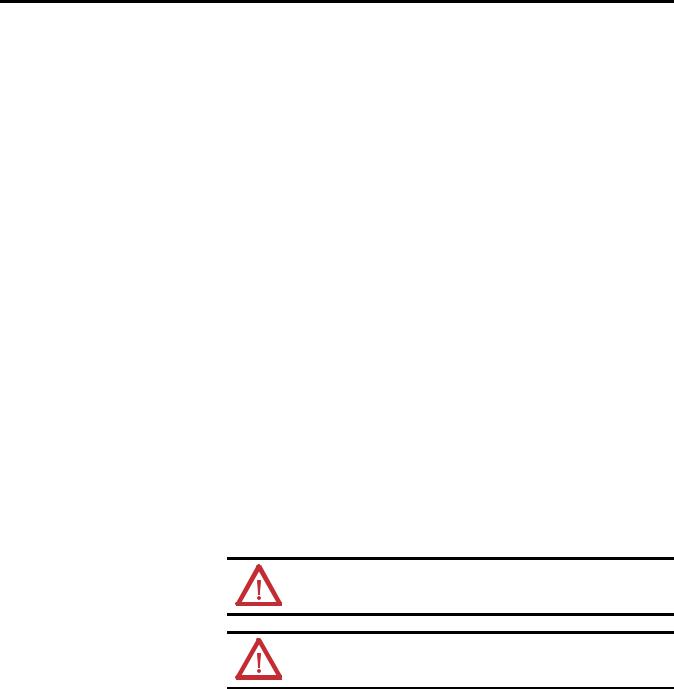
Six-channel Trimpot — 2080-TRIMPOT6
This trimpot plug-in offers an affordable method of adding six analog presets for speed, position and temperature control.
Channels
0 1 2
45068 |
3 |
4 |
5 |
High Speed Counter — 2080-MOT-HSC
This plug-in module provides enhanced high speed counter capabilities to the Micro800 controller. It supports the same functionalities of an embedded HSC on the Micro800 controllers but is enhanced to support up to 250 KHz 5V differential line driver for improved noise immunity and provides additional dedicated I/O.
For more information, see High Speed Counter – 2080-MOT-HSC on page 25.
Communication Plug-ins |
RS232/RS485 Isolated Serial Port — 2080-SERIALISOL |
The 2080-SERIALISOL plug-in supports CIP Serial (RS-232 only), Modbus
RTU (RS232 and RS485), and ASCII (RS232 and RS485(1)) protocols. Unlike the embedded Micro800 serial port, this port is electrically isolated, making it ideal for connecting to noisy devices, such as variable frequency and servo drives,
(1) RS-485 support is only available from Connected Components Workbench revision 6.
4 |
Rockwell Automation Publication 2080-UM004B-EN-E - December 2013 |

Micro800 Plug-in Modules |
Chapter 1 |
|
|
as well as for communications over long cable lengths. Depending on the application and baud rate setting, you can extend this length.
IMPORTANT 2080-SERIALISOL is suitable for communication over longer cable length of up to 1000 m using RS485, with up to 19200 bps baud rate.
The electrical characteristics of cable used and good wiring practices are very critical in achieving reliable communication performance over longer cable length. A shielded twisted pair RS485 22AWG cable (example:
3106A from Belden) is recommended. Terminate both ends of the cable with 120 ohm resistance.
DeviceNet Scanner — 2080-DNET20
The Micro800 DeviceNet plug-in module serves as a scanner and client for explicit messaging to remote devices including I/O and drives, using a proven and well-accepted fieldbus/network. It also provides better performance than using serial and Ethernet (EtherNet/IP Class 3) communications.
For more information, see the DeviceNet Plug-in – 2080-DNET20 on page 39.
Rockwell Automation Publication 2080-UM004B-EN-E - December 2013 |
5 |

Chapter 1 Micro800 Plug-in Modules
Notes:
6 |
Rockwell Automation Publication 2080-UM004B-EN-E - December 2013 |
Chapter 2
Install and Wire Your Module
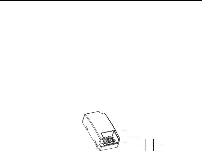
Hardware Features
This chapter provides hardware features, installation, and wiring connection diagrams for all the Micro800 plug-in modules.
The plug-in modules, except for the 2080-MEMBAK-RTC, can be plugged into any plug-in slots on the Micro800 controllers.
|
2080-RTD2 shown |
Measurements in millimeters (inches) |
|
|
|
31.5 |
|
|
|
20 |
|
|
|
(1.24) |
|
|
mounting screw |
(0.79) |
|
|
|
||
|
hole |
|
|
|
|
|
62 |
|
|
|
(2.44) |
|
terminal |
|
|
|
block |
|
|
mounting |
|
|
|
screw hole |
45010 |
|
|
|
|
|
45811 |
|
|
Side view |
Front view |
Insert Module into Controller
Follow the instructions to insert and secure the plug-in module to the controller.
45012
Rockwell Automation Publication 2080-UM004B-EN-E - December 2013 |
7 |

Chapter 2 Install and Wire Your Module
1.Position the plug-in module with the terminal block facing the front of the controller as shown.
2.Snap the module into the module bay.
3.Using a screwdriver, tighten the 10…12 mm (0.39…0.47 in.) M3 self tapping screw to torque specifications.
See Specifications on page 57 for torque specifications.
Wiring
IMPORTANT Analog I/O performance depends on the application. For better noise immunity, cable length should ideally be less than 10 m because the plug-ins are non-isolated. For longer cable length requirements, use the 2085 expansion I/O modules instead.
The following plug-in modules have 12-pin female terminal blocks:
•2080-IQ4,
•2080-IQ4OB4, 2080-IQ4OV4
•2080-OB4, 2080-OV4, 2080-OW4I
•2080-IF2, 2080-IF4
•2080-TC2, 2080-RTD2
|
|
|
Back |
|
|
|
B |
1 |
2 |
3 |
4 |
5 |
6 |
A |
1 |
2 |
3 |
4 |
5 |
6 |
Front
Twelve-pin Female Terminal Block
Pin Designations for 12-Pin Female Terminal Block Modules
Pin |
2080-IQ4 |
2080-IQ4OB4, |
2080-OB4, |
2080-OW4I |
2080-IF2 |
2080-IF4 |
2080-TC2 |
2080-RTD2 |
|
|
2080-IQ4OV4 |
2080-OV4 |
|
|
|
|
|
|
|
|
|
|
|
|
|
|
A1 |
I-02 |
I-02 |
Not used |
COM3 |
COM |
COM |
CH0+ |
CH0+ |
|
|
|
|
|
|
|
|
|
|
|
|
|
|
|
|
|
|
A2 |
I-03 |
I-03 |
Not used |
O-3 |
Not used |
VI-2 |
CH0- |
CH0- |
|
|
|
|
|
|
|
|
|
|
|
|
|
|
|
|
|
|
A3 |
COM |
COM |
-24V DC |
Not used |
Not used |
CI-2 |
CJC+ |
CH0L (Sense) |
|
|
|
|
|
|
|
|
|
|
|
|
|
|
|
|
|
|
A4 |
COM |
-24V DC |
-24V DC |
Not used |
COM |
COM |
Not used |
Not used |
|
|
|
|
|
|
|
|
|
|
|
|
|
|
|
|
|
|
A5 |
Not used |
O-02 |
O-02 |
Not used |
Not used |
VI-3 |
Not used |
Not used |
|
|
|
|
|
|
|
|
|
|
|
|
|
|
|
|
|
|
A6 |
Not used |
O-03 |
O-03 |
Not used |
Not used |
CI-3 |
Not used |
Not used |
|
|
|
|
|
|
|
|
|
|
|
|
|
|
|
|
|
|
B1 |
I-00 |
I-00 |
Not used |
COM0 |
VI-0 |
VI-0 |
CH1+ |
CH1+ |
|
|
|
|
|
|
|
|
|
|
|
|
|
|
|
|
|
|
B2 |
I-01 |
I-01 |
Not used |
O-0 |
CI-0 |
CI-0 |
CH1- |
CH1- |
|
|
|
|
|
|
|
|
|
|
|
|
|
|
|
|
|
|
B3 |
COM |
COM |
+24V DC |
COM1 |
COM |
COM |
CJC- |
CH1L (Sense) |
|
|
|
|
|
|
|
|
|
|
|
|
|
|
|
|
|
|
B4 |
COM |
+24V DC |
+24V DC |
O-1 |
VI-1 |
VI-1 |
Not used |
Not used |
|
|
|
|
|
|
|
|
|
|
|
|
|
|
|
|
|
|
B5 |
Not used |
O-00 |
O-00 |
COM2 |
CI-1 |
CI-1 |
Not used |
Not used |
|
|
|
|
|
|
|
|
|
|
|
|
|
|
|
|
|
|
B6 |
Not used |
O-01 |
O-01 |
O-2 |
COM |
COM |
Not used |
Not used |
|
|
|
|
|
|
|
|
|
|
|
|
|
|
|
|
|
|
8 |
Rockwell Automation Publication 2080-UM004B-EN-E - December 2013 |

Install and Wire Your Module |
Chapter 2 |
|
|
Back
B 1 2 3 4
A 1 2 3 4
Front Eight-pin female terminal block
The following plug-in modules have eight-pin female terminal blocks:
•2080-OF2
•2080-SERIALISOL
•2080-MOT-HSC
Pin Designations for 8-Pin Female Terminal Block Modules
Pin |
2080-OF2 |
2080-SERIALISOL |
2080-MOT-HSC(1) (2) |
A1 |
COM |
RS485 B+ |
O- |
|
|
|
|
|
|
|
|
A2 |
COM |
GND |
A- |
|
|
|
|
|
|
|
|
A3 |
COM |
RS232 RTS |
B- |
|
|
|
|
|
|
|
|
A4 |
COM |
RS232 CTS |
Z- |
|
|
|
|
|
|
|
|
B1 |
VO-0 |
RS232 DCD |
O+ |
|
|
|
|
|
|
|
|
B2 |
CO-0 |
RS232 RXD |
A+ |
|
|
|
|
|
|
|
|
B3 |
VO-1 |
RS232 TXD |
B+ |
|
|
|
|
|
|
|
|
B4 |
CO-1 |
RS485 A- |
Z+ |
|
|
|
|
|
|
|
|
(1)IMPORTANT: Individually shielded, twisted-pair cable (or the type recommended by the encoder or sensor manufacturer) should be used for the 2080-MOT-HSC plug-in.
(2)Sinking Output/Sourcing Output wiring for the 2080-MOT-HSC plug-in is shown below.
Sinking Output Wiring |
|
|
|
Sourcing Output Wiring |
|
|||||||
|
|
|
|
|
|
|
|
|
|
|
|
DC(+) |
|
|
|
|
|
|
|
|
|
|
|
|
|
|
|
0+ |
CR |
DC(+) |
CR |
0- |
0+ |
|
|
|
||
|
0- |
|
|
|
||||||||
|
|
|
|
|
|
|
|
|
||||
|
|
|
|
|
|
|
|
|
||||
|
|
|
|
|
|
|
A+ |
|
|
|
||
|
|
A+ |
|
|
|
|
|
|
|
|
|
|
|
|
|
|
|
A- |
|
||||||
|
A- |
|
|
|
|
|
|
|
|
|||
|
|
|
|
|
|
|
|
|
|
|
||
|
|
|
|
|
B+ |
|
|
|
||||
|
B+ |
|
|
|
|
|
|
|
|
|||
|
|
|
|
|
|
|
|
|
|
|
||
|
|
|
|
|
B- |
|
||||||
|
B- |
|
|
|
|
|
|
|
|
|||
|
|
|
|
|
|
|
|
|
|
|
||
|
|
|
|
|
Z+ |
|
|
|
||||
|
Z+ |
|
|
|
|
|
|
|
|
|||
|
|
|
|
|
|
|
|
|
|
|
||
|
|
|
|
|
Z- |
|
||||||
|
Z- |
|
|
DC(-) |
|
|
|
|
DC(-) |
|||
|
|
|
|
|
|
|
|
|
||||
|
|
|
|
|
|
|
|
|
|
|
||
|
|
|
|
|
|
|
|
|
|
|
||
|
|
|
|
|
|
|
|
|
|
|
||
|
|
|
|
|
|
|
|
|
|
|
||
|
|
|
|
|
|
|
|
|
|
|
||
Rockwell Automation Publication 2080-UM004B-EN-E - December 2013 |
9 |
Chapter 2 Install and Wire Your Module
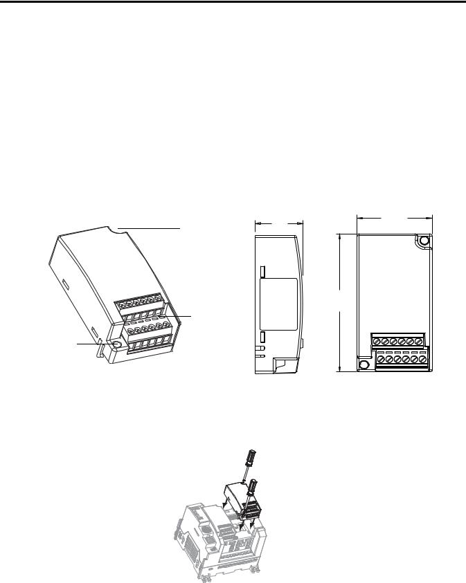
Serial Port to Modem Cable Pinout
When connecting Micro800 to a modem using an RS-232 cable, the maximum that the cable length may be extended is 15.24 m (50 ft).
DTE Device |
DCE Device |
(Micro800 RS232 |
(Modem, and |
Isolated Serial Port |
so on) |
Plug-in Module) |
|
8-Pin
B3 |
TXD |
|
|
B2 |
RXD |
|
|
A2 |
GND |
|
|
A1 |
B(+) |
|
|
B4 |
A(-) |
|
|
B1 |
DCD |
|
|
A4 |
CTS |
|
|
A3 |
RTS |
|
|
|
25-Pin |
9-Pin |
|
|
|
TXD |
2 |
3 |
|
|
|
RXD |
3 |
2 |
|
|
|
GND |
7 |
5 |
|
|
|
DCD |
8 |
1 |
|
|
|
DTR |
20 |
4 |
|
|
|
DSR |
6 |
6 |
|
|
|
CTS |
5 |
8 |
|
|
|
RTS |
4 |
7 |
|
|
|
ATTENTION: Do not connect to pins A1 and B4 for RS-232 connections. This connection will cause damage to the RS-232/485 communication port.
10 |
Rockwell Automation Publication 2080-UM004B-EN-E - December 2013 |
Install and Wire Your Module |
Chapter 2 |
|
|
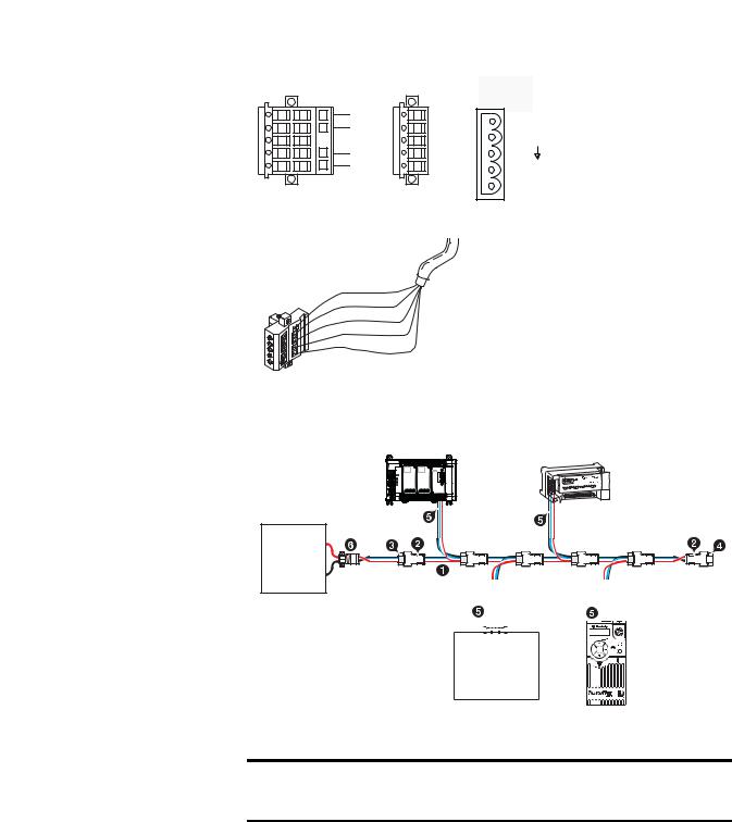
2080-DNET20 – 6-pin Female Terminal Block
Color Chips (dots) |
|
DeviceNet |
|
|
|
||
|
|
Port Pinout |
|
Red Dot |
|
V+ (RED) |
|
White Dot |
|||
CANH (WHITE) |
|||
|
|
||
Blue Dot |
|
SHIELD |
|
Black Dot |
CANL (BLUE) |
||
|
|
||
10-position Plug |
5-position Plug |
V- (BLACK) |
|
|
|||
10-position |
Red |
|
Linear Plug |
White |
DeviceNet |
|
||
|
Bare |
Drop Line or |
|
Blue |
Trunk Cable |
|
|
|
D |
Black |
|
D |
|
|
D |
|
|
D |
|
|
D |
|
|
20474
2080-DNET20: Sample network wiring using KwikLink™ Lite Flat media
Micro800 controller
CompactBlock LDX
COMM power supply
1 KwikLink Lite IP20 flat media |
|
|
|
|
|
|
|
|
2 Trunk line connector |
|
|
|
|
|
|
|
PowerFlex |
|
|
|
|
|
|
|
||
|
|
|
|
|
|
|
||
|
|
|
|
|
|
|
||
3 Drop line connector |
Component on |
Esc Sel |
|
Drive 523 via |
||||
4 Terminating resistor |
DeviceNet |
|
|
25-COMM-D |
||||
5 5-pin open style connector |
network |
|
|
|
||||
6 Power tap with terminating resistor |
|
|
|
|
|
|
46220 |
|
|
|
|
|
|
|
|
||
IMPORTANT Individually shielded, twisted-pair cable (or the type recommended by the encoder or sensor manufacturer) should be used for the
2080-MOT-HSC plug-in.
Rockwell Automation Publication 2080-UM004B-EN-E - December 2013 |
11 |

Chapter 2 Install and Wire Your Module
Wiring Considerations and Applications for 2080-TC2
2.41 max
6.5 max
0.25
50 ± 2
Type of CJC Sensor
The CJC sensor is a non-polarized, passive negative temperature co-efficient thermistor (EPCOS B57869S0502F140). It is readily available in the market with most third party suppliers/vendors.
IMPORTANT CJC Channel Error
The CJC channel on 2080-TC2 has a worst-case error of ±1.2 °C @ 25 °C. This error does not include the manufacturer-specified sensor error
±0.2 °C @ 25 °C.
Wire the CJC Thermistor on the 2080-TC2 Module
B1 B2 B3 B4 B5 B6
5m
|
5m |
|
|
|
B3 |
A3 |
|
|
|
|
A1 A2 |
A3 A4 |
A5 |
A6 |
1.Connect the thermocouples to channel 0 and 1, respectively. Then, connect and screw the thermistor to terminals A3 and B3.
2.Once fitted, bend the black bead of the thermistor such that it makes contact with the A2 screw securely.
The position for the thermistor, as illustrated, helps to compensate for thermoelectric voltages developed at screw junction equally for thermocouples connected to channels 0 and 1. If the bead is not in proper contact with the screw, there will be deviation in readings due to inadequate isothermal compensation.
Wire the Thermocouple Module and Thermocouple Sensor
in the Field
Connect the thermocouple sensors directly to the module terminals.
12 |
Rockwell Automation Publication 2080-UM004B-EN-E - December 2013 |
Install and Wire Your Module Chapter 2
Direct sensor wiring
|
Shielded/sheathed thermocouple sensor |
|
|
2080-TC2 |
|||
|
|
|
|
|
|||
Blue |
Red |
Cable tray/conduit |
Red |
|
|
|
|
+ |
- |
Green |
|
|
|
||
Blue |
|
|
|
|
|
||
|
|
1 |
2 |
3 |
4 |
5 |
6 |
|
Process |
1 |
2 |
3 |
4 |
5 |
6 |
|
temperature |
|
|
|
|
|
|
|
measurement |
|
|
|
|
45790 |
|
|
|
|
|
|
|
|
|
ATTENTION: Direct wiring is the preferred method of wiring for thermocouples.
Wiring Considerations and Applications for 2080-RTD2
Two-wire and Three-Wire Wiring
1 |
2 |
3 |
3 Wire
1 2 3
45772
2 Wire
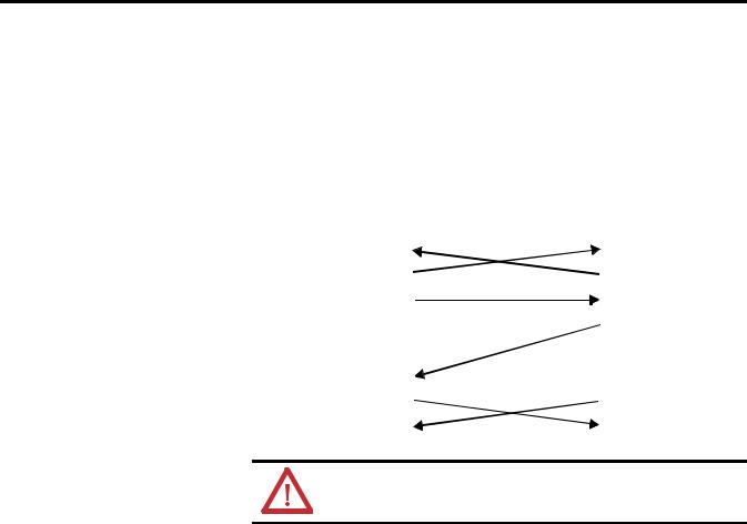
Wire the RTD Sensors
In an RTD sensor, the sensing element is always connected between two wires of different colors. Wires of the same color are shorted and form the compensation leads. Measuring resistance between these wires confirms the position of sensing element and compensation elements. Compensation elements will always show 0 ohms.
Rockwell Automation Publication 2080-UM004B-EN-E - December 2013 |
13 |

Chapter 2 Install and Wire Your Module
Wire the Sensors
white Ch0+ |
white |
Ch0+ |
|
red |
Ch0- |
|
|
|
|
Ch0- |
|
|
|
red |
|
|
Ch0L |
red |
Ch0L |
2-wire sensor |
3-wire single |
|
connection |
||
sensor connection |
||
|
NOTE: This illustration provides for channel 0 only for 2- and 3- wire single sensor connections. The wire colors illustrate a particular type of RTD sensor available in market.
white Ch0+
green Ch1+
black Ch1-
black Ch1L
red Ch0-
red Ch0L 45778
3-wire dual sensor connection
For better accuracy in noisy industrial environments, 3- or 4-wire RTD sensors are mostly used. While using these sensors, the resistance added by lead lengths is compensated by an additional third wire in case of 3-wire RTD and two additional wires, in bridge configuration, in case of 4-wire RTD. For 2-wire RTD sensor in this module, this lead compensation is provided by using an external 50 mm 22 AWG shorting wire between terminals A2, A3 and B2, B3 for channel 0 and 1, respectively. Shielded twisted pair cables are to be utilized for remote use of these sensors with cable shield grounded at controller end.
Wire the RTD Module and RTD Sensor in the Field
3-wire |
|
|
Shielded twisted wire cable |
|
|
2080-RTD2 |
|
|
|
|
|
|
|||
RTD |
|
|
|
|
|
||
|
|
Cable tray/conduit |
|
Black |
|
|
|
Blue |
Black |
Red |
Green |
Red |
|
|
|
|
|
|
Field screw |
Blue |
|
|
|
1 |
2 |
3 |
B |
1 2 3 |
4 5 6 |
||
|
|
|
junction box |
A |
1 2 3 |
4 5 |
6 |
|
|
|
|
||||
|
|
|
Oil filled |
|
|
|
|
|
|
|
thermowell |
|
|
|
|
|
|
|
|
3-wire RTD shown |
|||
Process temperature Measurement
45779
The RTD sensing element should always be connected between terminals B1(+) and B2(-) for channel 1, and A1(+) and A2(-) for channel 0 in the module. Terminals B3 and A3 should always be shorted to B2 and A2, respectively, to complete the constant current loop. Mismatch in wiring can cause erroneous, over, or underrange readings.
14 |
Rockwell Automation Publication 2080-UM004B-EN-E - December 2013 |

Install and Wire Your Module |
Chapter 2 |
|
|
IMPORTANT Cabling used with the 2080-TC2/RTD2 modules have to be shielded twisted cores with the shield wire shorted to chassis ground at controller end. It is advisable to use 22 AWG wires to connect the sensors to the module. Use sensors dipped in oil-filled thermowells for stable and uniform readings. Recommended cable type: Alpha wire P/N 5471C.
Performance is dependent on the application. For better noise immunity, cable length should ideally be less than 10 m because the plug-ins are non-isolated. For longer cable length requirements, use the 2085 expansion I/O modules instead.
Rockwell Automation Publication 2080-UM004B-EN-E - December 2013 |
15 |
Chapter 2 Install and Wire Your Module
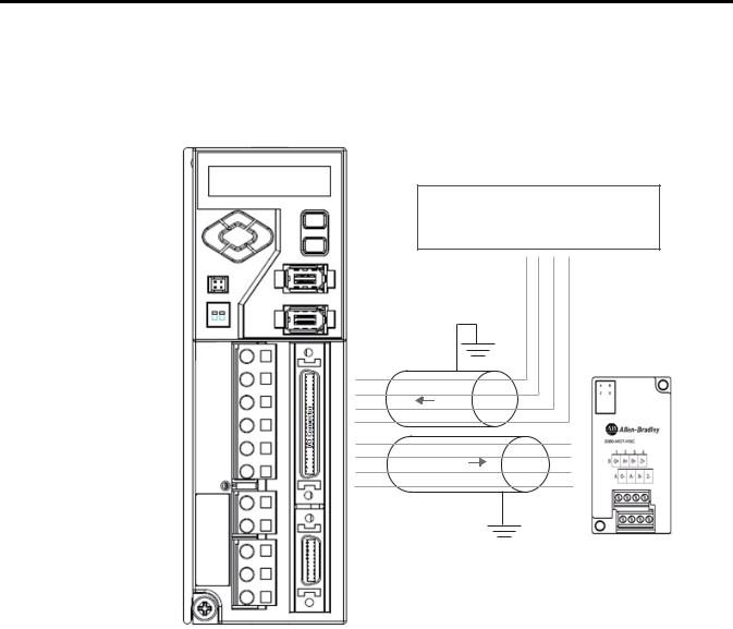
Wiring Applications for 2080-MOT-HSC
The following diagrams show wiring applications for the 2080-MOT-HSC plug-in with Kinetix® Servo drives.
Kinetix 3 in feedback configuration to 2080-MOT-HSC
Micro830/Micro850 QBB (24 pts)
|
|
|
O-00 |
-CM0 |
-CM1 |
O-03 |
|
I/O Connector |
|
|
|
||
|
49 |
= 24V_PULS+ |
|
|
|
|
|
12 |
= PLUS- |
|
|
|
|
|
14 |
= SIGN- |
|
|
|
|
|
25 |
= 24V_SIGN+ |
|
|
|
|
49 |
|
|
|
|
|
|
12 |
|
|
PTO |
|
|
|
14 |
|
|
|
|
|
|
25 |
|
|
|
|
|
|
29 |
|
|
|
|
A+ |
|
30 |
|
|
FEEDBACK |
|
A- |
|
31 |
|
|
|
B+ |
|
|
32 |
|
|
|
|
B- |
|
|
I/O Connector |
|
|
|
||
|
29 |
= AM+ |
|
|
|
|
|
30 |
= AM- |
|
|
|
|
|
31 |
= BM+ |
|
|
|
|
|
32 |
= BM- |
|
|
|
|
16 |
Rockwell Automation Publication 2080-UM004B-EN-E - December 2013 |
Install and Wire Your Module |
Chapter 2 |
|
|
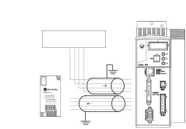
Kinetix 300 in feedback configuration to 2080-MOT-HSC
Micro830/Micro850 QBB (24 pts)
O-00 |
-CM0 |
-CM1 |
O-03 |
I/O Connector |
|
|
|
|
|
||
|
|
|
|
49 = 24V_PULS+ |
|
|
|
|
|
12 = PLUS- |
|
|
|
|
|
14 = SIGN- |
|
|
|
|
|
25 = 24V_SIGN+ |
|
|
|
|
|
|
1 |
|
|
|
|
|
2 |
|
|
|
PTO |
|
3 |
|
|
|
|
|
4 |
A+ |
|
|
|
|
7 |
A- |
|
|
FEEDBACK |
|
8 |
B+ |
|
|
|
9 |
|
B- |
|
|
|
|
10 |
|
|
|
|
I/O Connector |
|
|
|
|
|
29 |
= AM+ |
|
|
|
|
30 |
= AM- |
|
|
|
|
31 |
= BM+ |
|
|
|
|
32 |
= BM- |
Rockwell Automation Publication 2080-UM004B-EN-E - December 2013 |
17 |

Chapter 2 Install and Wire Your Module
Notes:
18 |
Rockwell Automation Publication 2080-UM004B-EN-E - December 2013 |

Chapter 3
Non-isolated Thermocouple and RTD
Plug-in Modules – 2080-TC2 and 2080-RTD2
Thermocouple Module
The Thermocouple (2080-TC2) and RTD (2080-RTD2) plug-in modules allow for temperature measure and control when used with PID.
This plug-in can be used in any slot of your Micro830/Micro850 controller. Removal and Insertion Under Power (RIUP) is not supported.
The 2080-TC2 two-channel plug-in module supports thermocouple measurement. It digitally converts and transmits temperature data from any combination of up to eight types of thermocouple sensors. Each input channel is individually configurable through the Connected Components Workbench software for a specific sensor, filter frequency.
Thermocouple Sensor Types and Ranges
The module supports B, E, J, K, N, R, S, T types of thermocouple sensors. The module channels are referred to as Channel 0, Channel 1, and CJC, respectively. The cold junction compensation is provided by an external NTC thermistor, which comes with the module. The thermistor has to be fitted to the screw terminals A3 and B3 of the module. This CJC is common to channel 0 and 1 thermocouple sensors and provides open-circuit, overrange and underrange detection and indication.
Overrange and Underrange Conditions
If the channel temperature input is below the minimum value of its normal temperature range for the represented sensor, the module reports an underrange error through the Connected Components Workbench global variables. If the channel reads above the maximum value of its normal temperature range for the represented sensor, an over-range error is flagged.
The table below defines thermocouple types and their associated full-scale temperature ranges.
Rockwell Automation Publication 2080-UM004B-EN-E - December 2013 |
19 |

Appendix 3 Non-isolated Thermocouple and RTD Plug-in Modules – 2080-TC2 and 2080-RTD2
RTD Module
Thermocouple Sensor Types and Temperature Ranges
Thermocouple |
Temperature Range |
Accuracy |
ADC Update |
|||
Type |
° C (°F) |
° C (°F) |
Rate in Hz |
|||
|
|
|
|
|
(Accuracy °C) |
|
|
Min |
Max |
±1.0 °C |
±3.0 °C |
||
|
|
|||||
|
|
|
|
|
|
|
B |
40 (104) |
1820 |
90…1700 |
< 90 (194) |
4.17, 6.25, 10, 16.7 |
|
|
|
(3308) |
(194…3092) |
> 1700 (3092) |
(±1.0) |
|
|
|
|
|
|
19.6, 33, 50, 62, |
|
E |
-270 (-454) |
1000 |
-200…930 |
< -200 (-328) |
||
123, 242, 470 (±3.0) |
||||||
|
|
(1832) |
(-328…1706) |
> 930 (1706) |
|
|
|
|
|
|
|
|
|
J |
-210 (-346) |
1200 |
-130…1100 |
< -130 (-202) |
|
|
|
|
(2192) |
(-202…2012) |
> 1100 (2012) |
|
|
|
|
|
|
|
|
|
K |
-270 (-454) |
1370 |
-200…1300 |
< -200 (-328) |
|
|
|
|
(2498) |
(-328…2372) |
> 1300 (2372) |
|
|
|
|
|
|
|
|
|
N |
-270 (-454) |
1300 |
-200…1200 |
< -200 (-328) |
|
|
|
|
(2372) |
(-328…2192) |
> 1200 (2192) |
|
|
|
|
|
|
|
|
|
R |
-50 (-58) |
1760 |
40…1640 |
< 40 (104) |
|
|
|
|
(3200) |
(104…2984) |
> 1640 (2984) |
|
|
|
|
|
|
|
|
|
S |
-50 (-58) |
1760 |
40…1640 |
< 40 (104) |
|
|
|
|
(3200) |
(104…2984) |
> 1640 (2984) |
|
|
|
|
|
|
|
|
|
T |
-270 (-454) |
400 |
-220…340 |
< -220 (-364) |
|
|
|
|
(752) |
(-364…644) |
> 340 (644) |
|
|
|
|
|
|
|
|
|
To configure Thermocouple type and update rate in Connected Components Workbench software, refer to the section Quickstart on page 77.
The 2080-RTD2 module supports RTD measurement applications that support up to two channels. The module digitally converts analog data and transmits the converted data in its image table.
The module supports connections from any combination of up to eleven types of RTD sensors. Each channel is individually configurable through the Connected Components Workbench software. When configured for RTD inputs, the module can convert the RTD readings into temperature data. Refer to Temperature Conversion – Data to Degree Celsius (°C) on page 23, for converting temperature data to actual temperature degree.
RTD Sensor Types and Ranges
Each channel provides open-circuit (all wires), short-circuit (excitation and return wires only), and overand under-range detection and indication. The 2080-RTD2 module supports 11 types of RTD sensors:
Pt100 385 |
PT1000 385 |
PT500 392 |
Ni120 672 |
PT200 385 |
PT100 392 |
PT1000 392 |
NiFe604 518 |
PT500 385 |
PT200 392 |
Cu10 427 |
|
20 |
Rockwell Automation Publication 2080-UM004B-EN-E - December 2013 |

Non-isolated Thermocouple and RTD Plug-in Modules – 2080-TC2 and 2080-RTD2 |
Appendix 3 |
|
|
It supports twoand three-wire type of RTD sensor wiring.
RTD Compatibility
An RTD consists of a temperature-sensing element connected by two, three, or four wires that provide resistance input to the module. The following table lists the RTD types that you can use with the module, including their temperature range, accuracy, and ADC update rate.
Overrange and Underrange Conditions
If the channel temperature input is below the minimum value of its normal temperature range for the represented sensor, the module reports an underrange error through the Connected Components Workbench global variables. If the channel temperature input is above the maximum value of its normal temperature range for the represented sensor, an over-range error is flagged.
RTD Sensor Types and Temperature Ranges
RTD Type |
Temperature |
Accuracy ° C (°F) |
ADC Update |
|||
|
Range ° C (°F) |
|
|
Rate in Hz |
||
|
|
|
|
|
(Accuracy °C) |
|
|
Min |
Max |
±1.0 °C |
±3.0 °C |
||
|
|
|||||
|
|
|
|
|
|
|
PT100 385 |
-200 |
660 |
-150…590 |
< -150 (-238) |
3-wire others |
|
|
(-328) |
(1220) |
(-238…1094) |
> 590 (1094) |
4.17, 6.25, 10, 16.7,19.6, |
|
|
|
|
|
|
33, 50 (±1.0) |
|
PT200 385 |
-200 |
630 |
-150…570 |
< -150 (-238) |
||
62, 123, 242, 470 (±3.0) |
||||||
|
(-328) |
(1166) |
(-238…1058) |
> 570 (1058) |
||
|
|
|||||
|
|
|
|
|
2- and 3-wire Cu10(1) |
|
PT500 385 |
-200 |
630 |
-150…580 |
< -150 (-238) |
||
|
(-328) |
(1166) |
(-238…1076) |
> 580 (1076) |
4.17, 6.25, 10, 16.7 |
|
PT1000 385 |
-200 |
630 |
-150…570 |
< -150 (-238) |
(>±1.0 < ±3.0) |
|
19.6, 33, 50, 62, 123, 242, |
||||||
|
(-328) |
(1166) |
(-238…1058) |
> 570 (1058) |
||
|
470 (> ±3.0) |
|||||
|
|
|
|
|
||
PT100 392 |
-200 |
660 |
-150…590 |
< -150 (-238) |
2-wire others |
|
|
(-328) |
(1220) |
(-238…1094) |
> 590 (1094) |
||
|
|
|
|
|
4.17, 6.25, 10, 16.7 (±1.0) |
|
PT200 392 |
-200 |
630 |
-150…570 |
< -150 (-238) |
||
19.6, 33, 50, 62, 123, 242, |
||||||
|
(-328) |
(1166) |
(-238…1058) |
> 570 (1058) |
||
|
470 (±3.0) |
|||||
|
|
|
|
|
||
PT500 392 |
-200 |
630 |
-150…580 |
< -150 (-238) |
|
|
|
(-328) |
(1166) |
(-238…1076) |
> 580 (1076) |
|
|
|
|
|
|
|
|
|
PT1000 392 |
-50 |
500 |
-20…450 |
< - 20 (-4) |
|
|
|
(-58) |
(932) |
(-4…842) |
> 450 (842) |
|
|
|
|
|
|
|
|
|
Cu10 427(1) |
-100 |
260 |
|
< -70 (-94) |
|
|
|
(-148) |
(500) |
|
> 220 (428) |
|
|
|
|
|
|
|
|
|
Ni120 672 |
-80 |
260 |
-50…220 |
< -50 (-58) |
|
|
|
(-112) |
(500) |
(-58…428) |
> 220 (428) |
|
|
|
|
|
|
|
|
|
NiFe604 518 |
-200 |
200 |
-170…170 |
< -170 (-274) |
|
|
|
(-328) |
(392) |
(-274…338) |
> 170 (338) |
|
|
|
|
|
|
|
|
|
(1)For Cu10 427, accuracy range is within >±1.0 < ±3.0 for -70…220 °C (-94…428 °F). Above this temperature range, it is > ±3.0 °C as shown in the table.
Rockwell Automation Publication 2080-UM004B-EN-E - December 2013 |
21 |

Appendix 3 Non-isolated Thermocouple and RTD Plug-in Modules – 2080-TC2 and 2080-RTD2
Connected Components
Workbench Global
Variables
Data Maps
The following bit/words describe the information read from the Thermocouple and RTD plug-in modules in the Connected Components Workbench Global Variables.
Mapping Table
Word Offset |
Bit |
|
|
|
|
|
|
|
|
|
|
|
|
|
|
|
|
|
|
|
|
|
|
|
|
|
|
|
|
|
15 |
|
13 |
|
12 |
|
11 |
|
10 |
|
09 |
|
08 |
|
07 |
|
06 |
|
05 |
|
04 |
|
03 |
|
02 |
|
01 |
|
00 |
|
14 |
|
|
|
|
|
|
|
|
|
|
|
|
|
|||||||||||||||
|
|
|
|
|
|
|
|
|
|
|
|
|
|
|
|
|
|
|
|
|
|
|
|
|
|
|
|
|
|
00 (example: _IO_P1_AI_00) |
|
|
|
|
|
|
|
|
|
|
Channel 0 Temperature Data |
|
|
|
|
|
|
|
|
|
|
|
|
||||||
|
|
|
|
|
|
|
|
|
|
|
|
|
|
|
|
|
|
|
|
|
|
|
|
||||||
01 (example: _IO_P1_AI_01) |
|
|
|
|
|
|
|
|
|
|
Channel 1 Temperature Data |
|
|
|
|
|
|
|
|
|
|
|
|
||||||
|
|
|
|
|
|
|
|
|
|
|
|
|
|
|
|
|
|
|
|
|
|
|
|
||||||
02 (example: _IO_P1_AI_02) |
|
|
|
|
|
|
|
|
|
|
Channel 0 Information |
|
|
|
|
|
|
|
|
|
|
|
|
||||||
|
|
|
|
|
|
|
|
|
|
|
|
|
|
|
|
|
|
|
|
|
|
|
|
|
|
|
|||
|
UKT |
UKR |
Reserved |
|
|
|
|
|
Reserved |
|
OR |
|
UR |
|
OC |
|
DI |
|
CC |
|
Reserved |
|
|
||||||
|
|
|
|
|
|
|
|
|
|
|
|
|
|
|
|
|
|
|
|
|
|
|
|
|
|
|
|
|
|
03 (example: _IO_P1_AI_03) |
|
|
|
|
|
|
|
|
|
|
Channel 1 Information |
|
|
|
|
|
|
|
|
|
|
|
|
||||||
|
|
|
|
|
|
|
|
|
|
|
|
|
|
|
|
|
|
|
|
|
|
|
|
|
|
|
|||
|
UKT |
UKR |
Reserved |
|
|
|
|
|
Reserved |
|
OR |
|
UR |
|
OC |
|
DI |
|
CC |
|
Reserved |
|
|
||||||
|
|
|
|
|
|
|
|
|
|
|
|
|
|
|
|
|
|
|
|
|
|
|
|
|
|
|
|
|
|
04 (example: _IO_P1_AI_04) |
|
|
|
|
|
|
|
|
|
|
|
System Information |
|
|
|
|
|
|
|
|
|
|
|
|
|||||
|
|
|
|
|
|
|
|
|
|
|
|
|
|
|
|
|
|
|
|
|
|
|
|
|
|
|
|
||
|
Reserved |
|
|
|
|
SOR |
|
SUR |
|
COC |
|
CE |
|
Reserved |
|
|
|
|
|
|
|
|
|
|
|
|
|||
|
|
|
|
|
|
|
|
|
|
|
|
|
|
|
|
|
|
|
|
|
|
|
|
|
|
|
|
|
|
Bit Definitions
Bit Name |
Description |
|
|
Channel Temperature Data |
The temperature count mapped from temperature Celsius degree |
|
with one decimal. Please check the section, Temperature |
|
Conversion – Data to Degree Celsius (°C) on page 23, for the |
|
mapping formula. |
|
|
UKT (Unknown Type) |
Bit set to report an unknown sensor type error in configuration. |
|
|
UKR (Unknown Rate) |
Bit set to report an unknown update rate error in configuration. |
|
|
OR (Overrange) |
Bit set to indicate overrange on channel input. The Channel |
|
Temperature Data shows maximum temperature count for |
|
individual type of sensor used and the value does not change |
|
until overrange error is clear. |
|
|
UR (Underrange) |
Bit set to indicate the channel input underrange happens. The |
|
Channel Temperature Data will show minimum temperature |
|
count for individual type of sensor used and the value does not |
|
change until underrange error is clear. |
|
|
OC (Open Circuit) |
Bit set to indicate open-circuit on the channel input sensor. |
|
|
DI (Data Illegal) |
The data in the channel data field is illegal and cannot be used |
|
by user. This bit is set when temperature data is not ready for |
|
use. |
|
|
CC (Code Calibrated) |
Bit set indicates temperature data is calibrated by the system |
|
calibration coefficient. |
|
|
SOR (System Overrange) |
Bit set to indicate system overrange error with environment |
|
temperature over 70 °C. |
|
|
SUR (System Underrange) |
Bit set to indicate system underrange error with environment |
|
temperature under -20 °C. |
|
|
COC (CJC open-circuit) |
Bit set to indicate CJC sensor not connected for thermocouple |
|
module, open circuit. This bit is for thermocouple module only. |
|
|
CE (Calibration Error) |
Bit set indicates that the module is not accurate. This bit is set to |
|
0 by default and should remain as 0. Contact Technical Support |
|
when the value is otherwise. |
|
|
22 |
Rockwell Automation Publication 2080-UM004B-EN-E - December 2013 |
Loading...