


 Loading...
Allen-Bradley |
|
Dataliner DL40 Plus |
User |
Message Display |
Manual |
Catalog No. 2706±LV2P, -LV4P, |
|
-LV2R, -LV4R |
|

Important User Information |
Solid state equipment has operational characteristics differing from those of |
||
|
electromechanical equipment. ªSafety Guidelines for the Application, |
||
|
Installation and Maintenance of Solid State Controlsº (Publication SGI-1.1) |
||
|
describes some important differences between solid state equipment and |
||
|
hard±wired electromechanical devices. Because of this difference, and also |
||
|
because of the wide variety of uses for solid state equipment, all persons |
||
|
responsible for applying this equipment must satisfy themselves that each |
||
|
intended application of this equipment is acceptable. |
||
|
In no event will the Allen-Bradley Company be responsible or liable for |
||
|
indirect or consequential damages resulting from the use or application of |
||
|
this equipment or software. |
||
|
The examples and diagrams in this manual are included solely for illustrative |
||
|
purposes. Because of the many variables and requirements associated with |
||
|
any particular installation, the Allen-Bradley Company cannot assume |
||
|
responsibility or liability for actual use based on the examples and diagrams. |
||
|
No patent liability is assumed by Allen-Bradley Company with respect to use |
||
|
of information, circuits, equipment, or software described in this manual. |
||
|
Reproduction of the contents of this manual, in whole or in part, without |
||
|
written permission of the Allen-Bradley Company is prohibited. |
||
|
Throughout this manual we use notes to make you aware of safety |
||
|
considerations. |
||
|
|
|
|
|
! |
ATTENTION: Identifies information about practices or |
|
|
circumstances that can lead to personal injury or death, property |
||
|
damage, or economic loss. |
||
|
|
|
|
Attentions help you:
•identify a hazard
•avoid the hazard
•recognize the consequences
Important: Identifies information that is especially important for successful application and understanding of the product.

o on n
Overview of the DL40 Plus
Using the Onboard Editor to Create Messages
Preface
Preface Objectives . . . . . . . . . . . . . . . . . . . . . . . . . . . . . . . . . . . |
P±1 |
Overview of this Manual . . . . . . . . . . . . . . . . . . . . . . . . . . . . . . . . |
P±1 |
Intended Audience . . . . . . . . . . . . . . . . . . . . . . . . . . . . . . . . . . . . |
P±2 |
Conventions Used . . . . . . . . . . . . . . . . . . . . . . . . . . . . . . . . . . . . |
P±2 |
Related Publications . . . . . . . . . . . . . . . . . . . . . . . . . . . . . . . . . . |
P±2 |
Enhanced Features of the DL40 Plus Message Displays . . . . . . . . . |
P±3 |
Chapter 1
Chapter Objectives . . . . . . . . . . . . . . . . . . . . . . . . . . . . . . . . . . . |
1±1 |
Available Configurations . . . . . . . . . . . . . . . . . . . . . . . . . . . . . . . . |
1±1 |
Message Support . . . . . . . . . . . . . . . . . . . . . . . . . . . . . . . . . . . . |
1±3 |
Programming Features . . . . . . . . . . . . . . . . . . . . . . . . . . . . . . . . . |
1±4 |
Operating Modes . . . . . . . . . . . . . . . . . . . . . . . . . . . . . . . . . . . . . |
1±11 |
Special Messages . . . . . . . . . . . . . . . . . . . . . . . . . . . . . . . . . . . . |
1±13 |
Controller Support for Remote I/O . . . . . . . . . . . . . . . . . . . . . . . . . |
1±14 |
Available Catalog Numbers . . . . . . . . . . . . . . . . . . . . . . . . . . . . . |
1±15 |
Compatible Keyboards . . . . . . . . . . . . . . . . . . . . . . . . . . . . . . . . . |
1±16 |
Options and Accessories . . . . . . . . . . . . . . . . . . . . . . . . . . . . . . . |
1±16 |
Repair Parts . . . . . . . . . . . . . . . . . . . . . . . . . . . . . . . . . . . . . . . . |
1±16 |
Chapter 2
Chapter Objectives . . . . . . . . . . . . . . . . . . . . . . . . . . . . . . . . . . . |
2±1 |
Programming Options . . . . . . . . . . . . . . . . . . . . . . . . . . . . . . . . . |
2±1 |
Entering the Onboard Editor . . . . . . . . . . . . . . . . . . . . . . . . . . . . . |
2±2 |
Exiting the Onboard Editor . . . . . . . . . . . . . . . . . . . . . . . . . . . . . . |
2±2 |
Onboard Editor Menu . . . . . . . . . . . . . . . . . . . . . . . . . . . . . . . . . . |
2±3 |
Creating or Editing Messages . . . . . . . . . . . . . . . . . . . . . . . . . . . . |
2±4 |
Keyboard Functions . . . . . . . . . . . . . . . . . . . . . . . . . . . . . . . . . . . |
2±5 |
Inserting Variables in Messages . . . . . . . . . . . . . . . . . . . . . . . . . . |
2±6 |
Testing Messages . . . . . . . . . . . . . . . . . . . . . . . . . . . . . . . . . . . . |
2±9 |
Message Attributes . . . . . . . . . . . . . . . . . . . . . . . . . . . . . . . . . . . |
2±9 |
Onboard Editor Options . . . . . . . . . . . . . . . . . . . . . . . . . . . . . . . . |
2±15 |
Message Queue . . . . . . . . . . . . . . . . . . . . . . . . . . . . . . . . . . . . . |
2±19 |
Publication 2706-6.1

toc±ii Table of Contents
Using Special Messages
Offline Operating Modes
Online Operating Modes
Serial Port
Communications
Parallel Port
Communications
Chapter 3
Chapter Objectives . . . . . . . . . . . . . . . . . . . . . . . . . . . . . . . . . . . |
3±1 |
What are Special Messages? . . . . . . . . . . . . . . . . . . . . . . . . . . . . |
3±1 |
Description of Special Messages . . . . . . . . . . . . . . . . . . . . . . . . . |
3±1 |
Chapter 4
Chapter Objectives . . . . . . . . . . . . . . . . . . . . . . . . . . . . . . . . . . . |
4±1 |
Help Mode . . . . . . . . . . . . . . . . . . . . . . . . . . . . . . . . . . . . . . . . . |
4±1 |
Historical Recall Mode . . . . . . . . . . . . . . . . . . . . . . . . . . . . . . . . . |
4±1 |
Remote Program Mode . . . . . . . . . . . . . . . . . . . . . . . . . . . . . . . . |
4±6 |
Set Port Parameters Mode . . . . . . . . . . . . . . . . . . . . . . . . . . . . . . |
4±7 |
Clock Mode . . . . . . . . . . . . . . . . . . . . . . . . . . . . . . . . . . . . . . . . . |
4±9 |
Print Mode . . . . . . . . . . . . . . . . . . . . . . . . . . . . . . . . . . . . . . . . . |
4±11 |
Debug Mode . . . . . . . . . . . . . . . . . . . . . . . . . . . . . . . . . . . . . . . . |
4±11 |
Chapter 5
Chapter Objectives . . . . . . . . . . . . . . . . . . . . . . . . . . . . . . . . . . . |
5±1 |
Run Mode Operations . . . . . . . . . . . . . . . . . . . . . . . . . . . . . . . . . |
5±1 |
Message/Variable/Slave Mode . . . . . . . . . . . . . . . . . . . . . . . . . . . |
5±2 |
Message/Variable Mode . . . . . . . . . . . . . . . . . . . . . . . . . . . . . . . . |
5±2 |
Message List Mode . . . . . . . . . . . . . . . . . . . . . . . . . . . . . . . . . . . |
5±3 |
Bit Trigger Mode . . . . . . . . . . . . . . . . . . . . . . . . . . . . . . . . . . . . . |
5±3 |
Chapter 6
Chapter Objectives . . . . . . . . . . . . . . . . . . . . . . . . . . . . . . . . . . . |
6±1 |
Overview of the Serial Ports . . . . . . . . . . . . . . . . . . . . . . . . . . . . . |
6±1 |
Using the RS-232 Port . . . . . . . . . . . . . . . . . . . . . . . . . . . . . . . . . |
6±2 |
Using the RS-485 Port . . . . . . . . . . . . . . . . . . . . . . . . . . . . . . . . . |
6±3 |
Using the Keyboard Port . . . . . . . . . . . . . . . . . . . . . . . . . . . . . . . |
6±4 |
Triggering Messages using Open Protocol . . . . . . . . . . . . . . . . . . . |
6±5 |
Sending Binary/BCD Variables using Open Protocol . . . . . . . . . . . . |
6±9 |
Sending ASCII/BCD Variables using Open Protocol . . . . . . . . . . . . |
6±10 |
Sending ASCII Data from the Keyboard Port . . . . . . . . . . . . . . . . . |
6±11 |
Returning ASCII Data from the RS-232/RS-485 Port . . . . . . . . . . . . |
6±12 |
Chapter 7
Chapter Objectives . . . . . . . . . . . . . . . . . . . . . . . . . . . . . . . . . . . |
7±1 |
Types of Run Modes . . . . . . . . . . . . . . . . . . . . . . . . . . . . . . . . . . |
7±1 |
Describing the Parallel Port . . . . . . . . . . . . . . . . . . . . . . . . . . . . . |
7±3 |
Selecting Binary or BCD Data . . . . . . . . . . . . . . . . . . . . . . . . . . . . |
7±4 |
Logic Voltage Levels . . . . . . . . . . . . . . . . . . . . . . . . . . . . . . . . . . |
7±6 |
Message/Variable/Slave Run Mode . . . . . . . . . . . . . . . . . . . . . . . . |
7±7 |
Message List Run Mode . . . . . . . . . . . . . . . . . . . . . . . . . . . . . . . . |
7±10 |
Sampling . . . . . . . . . . . . . . . . . . . . . . . . . . . . . . . . . . . . . . . . . . |
7±12 |
Publication 2706-6.1
Table of Contents |
toc±iii |
Remote I/O
Communications
Installation and Wiring
Chapter 8
Chapter Objectives . . . . . . . . . . . . . . . . . . . . . . . . . . . . . . . . . . . |
8±1 |
Overview of Remote I/O Communications . . . . . . . . . . . . . . . . . . . |
8±2 |
Remote I/O Terminology . . . . . . . . . . . . . . . . . . . . . . . . . . . . . . . . |
8±4 |
Typical Configurations . . . . . . . . . . . . . . . . . . . . . . . . . . . . . . . . . |
8±8 |
Processors and Corresponding Scanners . . . . . . . . . . . . . . . . . . . |
8±10 |
Physical vs. Logical Addressing . . . . . . . . . . . . . . . . . . . . . . . . . . |
8±11 |
Triggering Messages . . . . . . . . . . . . . . . . . . . . . . . . . . . . . . . . . . |
8±13 |
Returning Data to the PLC . . . . . . . . . . . . . . . . . . . . . . . . . . . . . . |
8±14 |
Sending Variables . . . . . . . . . . . . . . . . . . . . . . . . . . . . . . . . . . . . |
8±15 |
Handshake Bit . . . . . . . . . . . . . . . . . . . . . . . . . . . . . . . . . . . . . . . |
8±16 |
Message/Variable/Slave Run Mode . . . . . . . . . . . . . . . . . . . . . . . . |
8±17 |
Message/Variable Run Mode . . . . . . . . . . . . . . . . . . . . . . . . . . . . |
8±25 |
Message List Run Mode . . . . . . . . . . . . . . . . . . . . . . . . . . . . . . . . |
8±26 |
Bit Trigger Run Mode . . . . . . . . . . . . . . . . . . . . . . . . . . . . . . . . . . |
8±32 |
Chapter 9
Chapter Objectives . . . . . . . . . . . . . . . . . . . . . . . . . . . . . . . . . . . |
9±1 |
Mounting the DL40 Plus . . . . . . . . . . . . . . . . . . . . . . . . . . . . . . . . |
9±1 |
Panel Cutout Dimensions of the 2-Line DL40 Plus . . . . . . . . . . . . . |
9±2 |
Panel Cutout Dimensions of the 4-Line DL40 Plus . . . . . . . . . . . . . |
9±3 |
Dimensions of the 2-Line DL40 Plus . . . . . . . . . . . . . . . . . . . . . . |
9±4 |
Dimensions of the 4-Line DL40 Plus . . . . . . . . . . . . . . . . . . . . . . . |
9±5 |
Electrical Precautions . . . . . . . . . . . . . . . . . . . . . . . . . . . . . . . . . . |
9±6 |
Input Voltage Requirements . . . . . . . . . . . . . . . . . . . . . . . . . . . . . |
9±6 |
Hazardous Location Installations . . . . . . . . . . . . . . . . . . . . . . . . . . |
9±6 |
Wiring the DL40 Plus . . . . . . . . . . . . . . . . . . . . . . . . . . . . . . . . . . |
9±7 |
Remote I/O Connector . . . . . . . . . . . . . . . . . . . . . . . . . . . . . . . . . |
9±8 |
Connecting to a Scanner Module . . . . . . . . . . . . . . . . . . . . . . . . . |
9±9 |
Parallel Port . . . . . . . . . . . . . . . . . . . . . . . . . . . . . . . . . . . . . . . . |
9±10 |
Connecting the RS-485 Port for Open Protocol . . . . . . . . . . . . . . . . |
9±11 |
Connecting a Programmer to the RS-485 Port . . . . . . . . . . . . . . . . |
9±12 |
Connecting DL Slaves to the RS-485 Port . . . . . . . . . . . . . . . . . . . |
9±13 |
RS-232 Port . . . . . . . . . . . . . . . . . . . . . . . . . . . . . . . . . . . . . . . . |
9±14 |
Alarm Relay . . . . . . . . . . . . . . . . . . . . . . . . . . . . . . . . . . . . . . . . |
9±14 |
Keyboard Port . . . . . . . . . . . . . . . . . . . . . . . . . . . . . . . . . . . . . . . |
9±14 |
AC Power Connector . . . . . . . . . . . . . . . . . . . . . . . . . . . . . . . . . . |
9±15 |
Publication 2706-6.1

toc±iv Table of Contents
DIP Switch Settings
Chapter 10
Chapter Objectives . . . . . . . . . . . . . . . . . . . . . . . . . . . . . . . . . . . 10±1 DIP Switches on Remote I/O Version . . . . . . . . . . . . . . . . . . . . . . 10±1 DIP Switches on Parallel Port Version . . . . . . . . . . . . . . . . . . . . . . 10±10
Appendix A ± Specifications
Appendix B ± Error & Status Messages
Appendix C ± Cables
Appendix D ± ASCII Character Sets
Appendix E ± Remote I/O Application Examples
Appendix F ± Serial and Parallel Port Examples
Index
Publication 2706-6.1

Preface
s n s n
Preface Objectives
Overview of this Manual
Read this chapter to familiarize yourself with the rest of the Dataliner DL40 Plus Message Display manual. You will learn about:
•contents of this manual
•intended audience
•conventions used
•enhanced features of the DL40 Plus Message Displays
This manual describes how to install and use your DL40 Plus Series Dataliner Message Display. The manual is organized as follows:
Chapter |
Title |
Purpose |
|
|
|
1 |
Overview of the DL40 Plus |
Describes main features and operating |
|
|
capabilities of the DL40 Plus. |
2 |
Using the Onboard Editor |
Describes how to use the Onboard |
|
to Create Messages |
Editor to edit messages and set |
|
|
message options. |
|
|
|
3 |
Using Special Messages |
Describes the use of special messages |
|
|
with the remote I/O and parallel port |
|
|
versions of the DL40 Plus. |
|
|
|
4 |
Offline Operating Modes |
Describes DL40 Plus message display |
|
|
operating modes other than run mode. |
|
|
|
5 |
Online Operating Modes |
Explains the various run modes |
|
|
available for the DL40 Plus. |
6 |
Serial Port Communications |
Explains the operation of the run modes |
|
|
for the serial ports. |
|
|
|
7 |
Parallel Port |
Describes the operations of the run |
|
Communications |
mode for the parallel port. |
|
|
|
8 |
Remote I/O |
Describes the operations of the run |
|
Communications |
mode for the remote I/O version. |
|
|
|
9 |
Installation and Wiring |
Provides instructions for mounting the |
|
|
DL40 Plus in a panel and wiring it to a |
|
|
control panel. |
|
|
|
10 |
DIP Switch Settings |
Setting DIP switches for remote I/O and |
|
|
parallel port versions. |
|
|
|
Appendix A |
Specifications |
Lists environmental and electrical specifi- |
|
|
cations. |
|
|
|
Appendix B |
Error & Status Messages |
Lists internal error messages. |
|
|
|
Appendix C |
Cables |
Lists available cable accessory products. |
|
|
|
Appendix D |
ASCII Character Sets |
Lists English, Cyrillic, and international |
|
|
character sets. |
Appendix E |
Remote I/O |
Shows ladder logic for triggering mes- |
|
Application Examples |
sages using Remote I/O communications |
Appendix F |
Serial and Parallel Port |
Shows ladder logic for triggering mes- |
|
Examples |
sages using serial and parallel port com- |
|
|
munications |
|
|
|
Inside Back |
Dataliner DL40 Plus |
Keyboard editing commands. |
Cover |
Keyboard Edit Commands |
|
Publication 2706-6.1
P±2 |
Using this Manual |
Intended Audience
Conventions Used
Related Publications
No special knowledge is needed to enter or edit messages. However, since the Dataliner message display must be connected to peripheral equipment, we assume you are familiar with communication terminology, especially when using the Remote I/O version with a PLC.
The following conventions are used in this manual:
•All menus and screens reproduced in this manual are approximate renderings of what you will see on your terminal screen. Allen-Bradley reserves the right to make minor modifications to any menu or screen to help improve performance.
•A symbol or word in brackets represents a single key that you press. These include keys such as [A] or [Delete]. Since the Dataliner can be programmed with a variety of keyboards or
terminals, the printing on your keyboard may be different from the symbol or word indicated in brackets. This manual uses to
specify the carriage return function of a keyboard. On your keyboard this may correspond to an [ENTER], , or [Return] key.
•The up caret, ^, may be used in place of the [CTRL] where space requires. For example, ^W means the same as [CTRL][W]. This means you should press [CTRL] and [W] keys simultaneously.
•DL40 Plus refers to the Dataliner DL40 Plus Message Display
Other publications to which you may want to refer include:
•Dataliner DL40 Plus Message Display Offline Programming Software User Manual, Publication 2706-6.2
•Dataliner DL40 Plus Series Slave Message Display User Manual, Publication 2706-6.3
Publication 2706-6.1
Using this Manual |
P±3 |
Enhanced Features
of the DL40 Plus Message
Displays
The Dataliner DL40 Plus Message Displays are the next generation of Allen±Bradley message displays, replacing the older Dataliner DL40, DL20, and DL10 Series Message Displays.
Software Enhancements
The Dataliner DL40 Plus is a superset of the Dataliner DL40 Series Message Display, providing additional functionality:
•Increased user application memory of 128K in all units
•Real-time clock with full year 2000 compliance
•RS±232 message triggering, serial ASCII protocol
•RS-232 point-to-point slave display communications
•Direct connectivity to PLC and SLC Channel 0 ports
•Concurrent RS-232 and RS-485 communications
•RS-232 auto±wakeup for offline programming
•Full 16K historical event stack, data logging memory
•Enhanced slave message display application support
•Power fail recovery during message editing
•3 character sets: English, Cyrillic and International (ISO 8859-1)
Hardware Enhancements
The new hardware of the DL40 Plus offers these benefits:
•Catalog number reductions: 20+ to 6 catalog listings
•Flash memory: increases user memory to 128K in all units
•New VFD display: brighter Vacuum Fluorescent Display with adjustable brightness from 0 to 100%
•Real-time clock: Y2K compliant with replaceable battery
•Isolated I/O ports: optically isolated RS-232, RS-485, Parallel port and IBM PC Keyboard port.
•Power supply upgrade: IEC 1131-2 compliant design
•Integral fuse: common for 120 or 240 VAC installations
•Reliability improvements with reduced electronic components
•Increased panel mount stud lengths: 0.5 to .625 inches
•Panel depth reduction: 4.53 to 3.00 inches
•Weight reduction: 7.3 to 3.7 lbs (2-line display) and 8.9 to 4.9 lbs (4-line display)
Publication 2706-6.1
P±4 |
Using this Manual |
Regulatory Enhancements
The DL40 Plus meets and is listed for the following environmental, safety, and European Union regulatory requirements:
•European Union Directive Compliance ± CE marked for: EMC Directive and LVD Directives. IEC 1131-2 Equipment Class I.
•UL Listed for Class I, Division 2, Groups A,B,C,D Hazardous Locations
•UL Listed for Class I, Zone 2, EX nAIIC and Aex nAIIC Hazardous Environments
•cUL Listed for Canadian Safety Standards
Panel Cutout
The DL40 Plus Message Displays fit into the same panel cutout as the previous DL40, DL20, and DL10 products allowing direct mechanical replacement for these products.
Offline Programming Software
Use the DL40 Plus Message Display Offline Programming Software (Catalog No. 2706-LSW) to create, edit, archive and transfer DL40 Plus application files to and from DL40 and DL40 Plus displays.
Application Files
The DL40 Plus displays are 100% backward compatible with applications developed for previous versions of the DL40 displays. You can download application files to the DL40 Plus displays using either the the old or new offline programming software.
You can open a DL20 application file in the DL40 Plus Offline Programming Software (Catalog No. 2706-LSW) and it will be automatically converted to a DL40 message file.
Publication 2706-6.1
Ch pter 1
Overview of the DL40 Plus
Chapter Objectives
Available Configurations
This chapter covers the following topics.
Section |
Page |
|
|
Available Configurations |
1±1 |
|
|
Message Support |
1±3 |
|
|
Programming Features |
1±4 |
|
|
Operating Modes |
1±11 |
|
|
Special Messages |
1±13 |
|
|
Controller Support for Remote I/O |
1±14 |
|
|
Available Catalog Numbers |
1±15 |
|
|
Compatible Keyboards |
1±16 |
|
|
Options and Accessories |
1±16 |
|
|
Repair Parts |
1±16 |
The DL40 Plus is available in a 2- or 4-line configuration (capable of displaying 20 characters per line) with either Remote I/O or Parallel port communication options.
Remote I/O Version
The Remote I/O version enables two-way communications with the Allen-Bradley family of PLCs and SLCs. A remote I/O version of the DL40 Plus can appear to the PLC or SLC as any size I/O rack (1/4, 1/2, 3/4, or full).
Parallel Port Version
The Parallel Port version receives message number triggers, slave addresses, and variable data from a PLC or SLC output module via 16 data lines and 4 strobe lines (indicating the type of data).

1±2 Overview of the DL40 Plus
RS-485/RS-232 Communications
Both the Remote I/O and Parallel Port versions have RS-485 and RS-232 ports. You can configure these ports for Programmer, DL Slave or Open Protocol communications (see table below). Port settings are modified through the Ports menu in the Offline Programming software or the Onboard Editor. You select a communication option under the Port Use submenu.
The RS-232 port always communicates with the Offline
Programming Software regardless of the configured mode. Open
Protocol or DL Slave operation can occur on either the RS-232 or
RS-485 port.
If the RS-485 port is configured for Open protocol, you cannot configure the RS-232 port for the same protocol. Instead, an information message reports an invalid port configuration.
Configurations |
Description |
DL40 Plus Port |
|
Communication/Printing Options |
|
|||
|
|
|
|
|
||||
Programmer |
|
Open Protocol |
Slave |
Printing |
||||
|
|
|
|
|
||||
|
|
|
|
|
|
|
|
|
1 |
|
Offline Programming |
RS±485 |
√ |
|
|
|
|
|
and Serial Printing |
RS±232 |
√ |
|
|
|
√ |
|
|
|
|
|
|
||||
2 |
|
RS-232 Offline Programming |
RS±485 |
|
|
√ |
|
|
|
and RS-485 Message Triggering |
RS±232 |
√ |
|
|
|
√ |
|
|
|
|
|
|
||||
3 |
|
RS-232 Offline Programming |
RS±485 |
|
|
|
√ |
|
|
RS-485 Slave Communications |
RS±232 |
√ |
|
|
|
√ |
|
|
|
|
|
|
||||
4 |
|
RS-485 Offline Programming |
RS±485 |
√ |
|
|
|
|
|
RS-232 Message Triggering |
RS±232 |
|
|
√ |
|
|
|
|
|
|
|
|
|
|||
5 |
|
RS-485 Slave Communications |
RS±485 |
|
|
|
√ |
|
|
RS-232 Message Triggering |
RS±232 |
|
|
√ |
|
|
|
|
|
|
|
|
|
|||
6 |
|
RS-485 Offline Programming |
RS±485 |
√ |
|
|
|
|
|
RS-232 Slave Communications |
RS±232 |
|
|
|
√ |
|
|
|
|
|
|
|
|
|||
7 |
|
RS-485 Message Triggering |
RS±485 |
|
|
√ |
|
|
|
RS-232 Slave Communications |
RS±232 |
|
|
|
√ |
|
|
|
|
|
|
|
|
|||
Note: Open protocol is a serial ASCII based format for triggering messages stored in the DL40 Plus displays. Open protocol supports message triggers with or without variable data over the RS-232 or RS-485 serial ports.
Publication 2706-6.1
Overview of the DL40 Plus |
1±3 |
Message Support
The DL40 Plus stores messages of varying length. Each message is identified by a unique message number from 1 to 9999. Messages are placed in an internal memory queue when triggered by a command from your control system. They are then run according to attributes selected in the DL40 Plus.
The DL40 Plus can display a wide variety of characters and symbols, including:
•Uppercase letters
•Lowercase letters
•Punctuation
•Special characters from the extended ASCII character set
•English character set (default)
•International character set ISO 8859±1
•Cyrillic character set (Russian)
Note: English characters are also available with both the International an Cyrillic character sets.
A person with normal vision can easily read the display from a distance of up to 25 feet.
Publication 2706-6.1
1±4 |
Overview of the DL40 Plus |
Programming Features
The DL40 Plus is a versatile status, prompt and diagnostic display tool, equipped with a full range of high-end programming and performance features.
DL40 Plus Capabilities |
Remote I/O |
Parallel Port |
|
Version |
Version |
||
|
|||
|
|
|
|
Supports offline programming software |
Yes |
Yes |
|
|
|
|
|
PLC-5 Remote I/O PassThrough via DH+ |
Yes |
No |
|
|
|
|
|
PLC-5E Remote I/O PassThrough via Ethernet |
Yes |
No |
|
|
|
|
|
International and Cyrillic character sets |
Yes |
Yes |
|
|
|
|
|
Onboard editing with PC keyboard |
Yes |
Yes |
|
|
|
|
|
Send ASCII data to a PLC via a Remote I/O link |
Yes |
No |
|
|
|
|
|
Send ASCII data to a device via an RS-485 link |
Yes |
Yes |
|
|
|
|
|
Communicates with any programmable controller |
No |
Yes |
|
|
|
|
|
Customizable historical events stack |
Yes |
Yes |
|
|
|
|
|
Real-time clock operations |
Yes |
Yes |
|
|
|
|
|
RS-232 and RS-485 ports |
Yes |
Yes |
|
|
|
|
|
Debug Mode |
No |
Yes |
|
|
|
|
|
Support for auxiliary devices such as slave displays |
Yes |
Yes |
|
and printers |
|||
|
|
||
|
|
|
|
Background messages |
Yes |
Yes |
|
|
|
|
|
Hidden messages |
Yes |
Yes |
|
|
|
|
|
Embedded variables |
Yes |
Yes |
|
|
|
|
|
Data mode selection |
Yes |
Yes |
|
|
|
|
|
Message chaining |
Yes |
Yes |
|
|
|
|
|
Adjustable parameters for serial communications |
Yes |
Yes |
|
|
|
|
|
Adjustable display brightness |
Yes |
Yes |
|
|
|
|
Publication 2706-6.1

Overview of the DL40 Plus |
1±5 |
Offline Programming Software
Create and edit application files using the Offline Programming Software (Catalog No. 2706-LSW) on a personal computer. With interactive menus you can quickly create messages, set message attributes, and download messages to one or more DL40 Plus displays.
Create Message editing screen |
Set Message Attributes window |
Download Message Files screen |
Convert DL20 files for use with a DL40 Plus |
The offline programming cable (Catalog No. 2706-NC13) provides a direct connection between a personal computer running the Offline Programming Software and a DL40 Plus. This 3-meter cable has a 9-pin, D-shell connector on each end.
Publication 2706-6.1
1±6 |
Overview of the DL40 Plus |
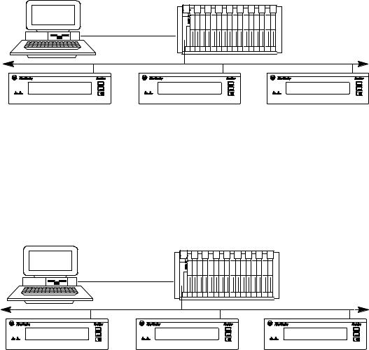
PLC-5 Remote I/O PassThrough Via DH+
PLC-5 Remote I/O PassThrough lets you upload and download message files between a computer and a DL40 Plus connected by Remote I/O to a PLC on the DH+ link. Separate wiring from the computer to the DL40 Plus is not required. For a list of supported controllers, see page 1±14.
Computer
|
DH+ Network |
|
|
Remote I/O Link |
Remote I/O Link |
DL40 Plus |
DL40 Plus |
DL40 Plus |
PLC-5E Remote I/O PassThrough Via Ethernet
PLC-5E Remote I/O PassThrough lets you upload and download message files between a computer and a DL40 Plus connected by Remote I/O to a PLC on the Ethernet link. Separate wiring from the computer to the DL40 Plus is not required. For a list of supported controllers, see page 1±15.
Computer
|
Ethernet Network |
|
|
Remote I/O Link |
Remote I/O Link |
DL40 Plus |
DL40 Plus |
DL40 Plus |
Publication 2706-6.1
Overview of the DL40 Plus |
1±7 |
International and Cyrillic Character Sets
The local language character sets let you create and display messages in other languages such as French, German, Italian, and Spanish with the Offline Programming Software with:
•English (default)
•International character set ISO 8859±1
•Cyrillic (Russian)
English characters are also available with both the International and
Cyrillic character sets.
Onboard Editor
With the Onboard Editor you can create or edit messages, select message attributes, and set options and variable formats using a standard IBM PC keyboard. The Keyboard port is located on the rear panel of the DL40 Plus.
Send ASCII Data to a PLC via Remote I/O Link
Using Remote I/O communications, you can send ASCII data to a PLC. Attach an IBM compatible keyboard to the DL40 Plus and you can enter part numbers, badge numbers, passwords, and similar information as required. The DL40 Plus processes and displays the information, and then sends it to the controller.
You can establish similar communications over an RS-232 or
RS-485 link.
Communicate with any Programmable Controller (Parallel Port Version)
The DL40 Plus accepts information from any programmable controller over a total of 20 input lines (16 data and 4 strobe lines).
Parallel Port versions of the DL40 Plus have an isolated 12 VDC supply output that can be used to power outputs that pull data and strobe lines high.
Backup Operations
Archive DL40 Plus application files in the Offline Programming Software (Catalog No. 2706-LSW) by uploading or downloading files between a computer and DL40 Plus displays.
Publication 2706-6.1
1±8 |
Overview of the DL40 Plus |
Historical Events Stack
The Historical Events Stack records the occurrence and sequence of some or all messages and logs variable data values that have been triggered and/or displayed. The 16K bytes of stack memory holds about 1,000 events. You can view information in chronological order or by frequency of occurrence, or print the record.
Clock Operations
A real-time battery-backed clock keeps accurate time even when power is removed from the unit. The DL40 Plus can display the current time and/or date in either AM/PM or 24-hour military format.
Note: The date function is year 2000 compliant.
Date and time information can be displayed as part of any triggered message, and passed on to a PLC. You can also dateor time-stamp events as they are recorded in the Historical Events Stack.
Set the DL40 Plus internal clock using the front panel menus, a keyboard connected to the Onboard Editor, a PLC, or the Offline Programming Software.
RS-232 and RS-485 Ports
The DL40 Plus has both an RS-232 and RS-485 port.
Use the RS-232 port to:
•upload or download message files from a computer
•trigger messages via Open protocol (ASCII triggering)
•send messages to a single slave message display
•print messages and/or the contents of the Historical Event Stack
Use the RS-485 port to:
•multi-drop upload or download message files from a computer
•trigger messages via Open protocol (ASCII triggering)
•send messages to one or more slave message displays
•input ASCII data via bar code
Publication 2706-6.1

Overview of the DL40 Plus |
1±9 |
Keyboard Port
Use the Keyboard port on the DL40 Plus to:
•edit options, messages, communication port settings
•input ASCII data to a host controller, PLC, or computer
•trigger messages using Open protocol (ASCII triggering)
Debug Mode (Parallel Port Version)
Use Debug mode to display the binary status (1 or 0 value) of the data lines and the state of the strobe lines. This mode is useful for checking the output of a programmable controller.
Auxiliary Devices
Connect a variety of useful auxiliary devices to the DL40 Plus display.
Slave Displays
Address up to 126 DL40 Plus or DL50 slave displays over an RS-485 network at distances up to 4,000 feet (1200 m) from the originating DL40 Plus. You can also control the annunciation relay on remote DL40 Plus or DL50 Series slave displays. By assigning a specific address to each slave display, you can control which slaves receive and display a given message.
Printers
Connect a serial printer to print the Historical Events Stack or a listing of the internal application file. The time and date a message was triggered can be included on the stack printout. You can also set message attributes such as sending triggered messages to a printer through the RS-232 port.
Alarms
The alarm relay activates or deactivates an external remote alarm or warning light. Individual message attributes can be set to energize or de-energize the alarm relay contacts on DL40 Plus or slave displays.
|
ATTENTION: Use the DL40 Plus alarm relay for |
|
! |
annunciation purposes only. Do not use the alarm relay |
|
for control applications. |
||
|
||
|
|
Publication 2706-6.1
1±10 |
Overview of the DL40 Plus |
Background Messages
Specify a background message that will display whenever the DL40 Plus has no other triggered messages in the queue.
Hidden Messages
Hidden messages do not appear on the DL40 Plus display or have any affect on what is being displayed. Hidden messages can be sent to a slave display, printed, or stored on the Historical Events Stack.
Embedded Variables
Messages can contain variable data. Variable values are received when the message is triggered. Incoming variable data can be binary, BCD (binary coded decimal), and/or ASCII. You can also embed time and date information in a message from the battery-backed real-time clock of the DL40 Plus.
Data Mode Selection
When using the DL40 Plus with Remote I/O or parallel input for communication, you can select two data modes:
•Binary
•Binary Coded Decimal (BCD) either signed or unsigned
Within any application, triggers and variable data can be in either form. For example, message triggers can be in a binary format, while variable data can be BCD.
Note: When using serial RS-232 or RS-485 communications, all data is in ASCII character format.
Message Chaining
Chain messages together for display in sequence. Only the first message in the chain is triggered from the host controller. Then each message in the chain can trigger the next until the complete sequence has run.
Publication 2706-6.1
Overview of the DL40 Plus |
1±11 |
Operating Modes
Adjustable Parameters for Serial Communications
With the DL40 Plus, you can configure RS-232 or RS-485 port parameters as needed for compatibility with PLCs/SLCs, printers, slave displays, or control computers.
Serial Communication Parameters |
Settings |
|
|
|
|
Baud Rate |
300, 1200, 2400, 4800, 9600, 19200 |
|
|
|
|
Parity |
Odd, Even, No Parity |
|
|
|
|
Handshake |
Software, Hardware, None |
|
|
|
|
Data Bits per Character |
7 or 8 |
|
|
|
|
|
0 to 255 |
|
Null Count |
Allows you send a string of nulls to the printer |
|
between characters. Useful with slow printers |
||
|
that drop characters because they can't keep |
|
|
up with normal DL40 Plus output. |
|
|
|
|
Page With |
20 ±132 characters |
|
Useful for narrow width printer devices. |
||
|
||
|
|
The DL40 Plus has a number of operating modes. Each mode provides tools to perform a different set of functions. The following sections provide a brief overview of the operating modes.
Run Mode
Run mode is the normal operating mode for the DL40 Plus. In Run mode, messages are triggered for display on the DL40 Plus and slave message displays (if desired).
The Remote I/O version of the DL40 Plus comes up in Run mode after a reset. The Parallel port version also comes up in Run mode, except when the Run Mode/Debug DIP switch is set to Debug on the DL40 Plus.
The Remote I/O version of the DL40 Plus has 4 Run modes.
•Message/Variable/Slave Mode triggers a message with 1 to 40 variables, depending on rack size, trigger method, and variable type. This mode allows you to override the slave address attribute.
•Message/Variable Mode is similar to the Message/Variable/Slave mode but you cannot override the slave address attribute.
•Message List Mode triggers a message list of up to 20 messages in round robin order.
•Bit Trigger Mode triggers a priority message and up to 496 messages in priority and/or round robin order.
Publication 2706-6.1
1±12 |
Overview of the DL40 Plus |
The Parallel port version of the DL40 Plus has 2 Run modes.
•Message/Variable/Slave Mode triggers a message with 1 to 40 variables, depending on trigger method, and variable type.
•Message List Mode triggers a message list of up to 20 messages in round robin order.
To select Run mode, use the Onboard Editor or the Offline Programming Software.
For more details on the various run modes, see Chapter 5, Online Operating Modes.
Serial Triggering (RS±232/RS±485)
Both the Remote I/O and the Parallel port versions of the DL40 Plus support serial triggering. The RS-232, RS-485, or Keyboard port can control message triggering and variable data communications.
Serial triggering uses Open protocol, which communicates using ASCII characters in a serial data stream. For detailed protocol specifications, refer to Chapter 6, Serial Port Communications.
Open protocol is available in the following run modes:
•Message/variable/slave mode
•Message/variable
•Message list
Offline Modes
The DL40 Plus offers the following offline operating modes:
•Help mode
•Historical Recall mode
•Remote Program mode (for Offline Programming Software)
•RS-232/RS-485 Port Configuration mode
•Clock mode
•Print mode
•Debug mode (on Parallel port versions only)
Publication 2706-6.1

Overview of the DL40 Plus |
1±13 |
Special Messages
Special messages let you monitor and control certain functions of the DL40 Plus without leaving Run Mode. Special messages normally occupy message numbers 901 through 916. You can move special messages to message numbers 1 to 16, or disable them with the Offline Programming Software or Onboard Editor. For a complete description of special messages see Chapter 3, Using Special
Messages.
Message Number |
Content |
||
|
|
|
|
901 |
(or 01) |
Terminate Message ± Clear Display |
|
|
|
|
|
902 |
(or 02) |
Clear Queue |
|
|
|
|
|
903 |
(or 03) |
Terminate Message ± Clear Display and Queue |
|
|
|
|
|
904 |
(or 04) |
Reset Unit |
|
|
|
|
|
905 |
(or 05) |
Test Display |
|
|
|
|
|
906 |
(or 06) |
Print Historical Events Stack ± Chronological Order |
|
|
|
|
|
907 |
(or 07) |
Print Historical Events Stack ± Frequency of |
|
Occurrence |
|||
|
|
||
908 |
(or 08) |
View Historical Events Stack |
|
|
|
|
|
909 |
(or 09) |
Clear Historical Events Stack |
|
|
|
|
|
910 |
(or 10) |
Set Interactive Clock |
|
|
|
|
|
911 |
(or 11) |
Set Clock with Variable Data |
|
|
|
|
|
912 |
(or 12) |
Send Time to PLC |
|
913 |
(or 13) |
Send Date to PLC |
|
914 |
(or 14) |
View Display Parameters |
|
|
|
|
|
915 |
(or 15) |
Stop Special Messages/Resume Run Mode |
|
|
|
|
|
916 |
(or 16) |
Set Display Intensity |
|
Remote I/O versions only
Publication 2706-6.1
1±14 |
Overview of the DL40 Plus |
Controller Support for Remote I/O
The following PLCs and SLCs support Remote I/O communications with the DL40 Plus.
•PLC-5/11, 5/15 , 5/20, 5/25, 5/30, 5/40, 5/60, 5/80, 5/250
•PLC-2, PLC-5/10, 5/12 with Catalog Number 1771-SN Scanner
•SLC-5/02, 5/03, 5/04 with Catalog Number 1747-SN Scanner
If you are using a PLC-5/15 with partial rack addressing and block transfers, you must use Series B, Rev. J or later.
Block Transfer requires a Series B or later Scanner.
PassThrough Support over a DH+ Link
The following tables list the Allen-Bradley PLCs that support PassThrough file transfers with the DL40 Plus over a DH+ link.
PLC Types |
Series |
Revision |
|
|
|
|
|
PLC-5/11 |
All |
All |
|
|
|
|
|
PLC-5/15 |
B |
N or later |
|
|
|
|
|
PLC 5/20 |
All |
All |
|
|
|
|
|
PLC 5/25 |
A |
J or later |
|
|
|
|
|
PLC 5/30 |
A |
B or later |
|
|
|
|
|
PLC 5/40 |
A |
E or later |
|
B |
|||
|
|
||
|
|
|
|
PLC 5/60 |
A |
B or later |
|
B |
|||
|
|
||
|
|
|
|
PLC 5/80 |
All |
All |
|
|
|
|
|
PLC 5/250 |
All |
All |
|
|
|
|
The table below lists the computer interface boards for PassThrough file transfers.
Catalog No. |
Description |
|
|
|
|
1784-KT |
1/ -slot interface board |
|
|
2 |
|
1784-KTX |
1/ -slot interface board |
|
|
2 |
|
1784-KL |
Interface board for Allen-Bradley 1784-T45 |
|
or -T47 |
||
|
||
|
|
|
1784-KT2 |
Interface module for IBM PS2 |
|
|
|
|
1770-KF2 |
Serial to DH+ interface module |
|
|
|
|
1784-PCMK |
PCMCIA interface board |
|
|
|
Publication 2706-6.1

Overview of the DL40 Plus |
1±15 |
PassThrough Support over an Ethernet Link
The following table lists the Allen-Bradley PLCs that support PassThrough file transfers with the DL40 Plus message display over an Ethernet link as of this printing.
PLC Types |
Series |
Revision |
|
|
|
PLC 5/40E |
A |
E or later |
B |
|
|
|
|
|
|
|
|
PLC 5/60E |
A |
B or later |
B |
|
|
|
|
|
|
|
|
PLC 5/80E |
All |
All |
|
|
|
PLC 5/250 |
All |
All |
|
|
|
Use one of the Allen-Bradley Ethernet computer interface boards (or its equivalent) for PassThrough file transfers.
•Catalog Number 6628-A5: Ethernet adapter module for IBM PC compatible computers
•Catalog Number 6628-A7: Ethernet adapter module for IBM MicroChannel bus compatible computers
Available Catalog Numbers DL40 Plus displays are available with 128K bytes of memory in either 2- or 4-line versions with two communication options.
2706±LV2R
Display Type: |
Communication Options: |
2 ± Two±line |
R ± RIO |
4 ± Four±line |
P ± Parallel Port |
|
S ± Slave |
The table below shows the standard catalog numbers for the DL40
Plus and how they equate to previous versions of the DL40 displays.
DL40 Plus |
Description |
Equivalent Catalog Numbers for |
|
Catalog Number |
Previous Versions of the DL40 |
||
|
|||
|
|
|
|
2706±LV2P |
Two±line display, AC supply |
2706±E23J16, 2706±E23C16 |
|
|
with parallel port |
2706±E23J32, 2706±E23C32 |
|
|
|
|
|
2706±LV4P |
Four±line display, AC supply |
2706±E43J32, 2706±E43C32 |
|
|
with parallel port |
2706±E43J64, 2706±E43C64 |
|
|
|
||
|
|
2706±E43J128, 2706±E43C128 |
|
|
|
|
|
2706±LV2R |
Two±line display, AC supply |
2706±E23J16B1, E23C16B1 |
|
|
with remote I/O |
2706±E23J32B1, 2706±E23C32B1 |
|
|
|
||
|
|
|
|
2706±LV4R |
Four±line display, AC supply |
2706±E43J32B1, 2706±E43C32B1 |
|
|
with remote I/O |
2706±E43J64B1, 2706±E43C64B1 |
|
|
|
||
|
|
2706±E43J128B1, 2706±E43C128B1 |
Publication 2706-6.1
1±16 |
Overview of the DL40 Plus |
Compatible Keyboards |
The following keyboards are compatible with the DL40 Plus. |
||
|
|
|
|
|
Catalog No. |
Description |
|
|
|
|
|
|
6189-KBD1 |
Industrial Keyboard |
|
|
|
|
|
|
6189-KBE1 |
Industrial Spill-Proof Keyboard |
|
|
|
|
|
|
6186-KBM1 |
Industrial Panel Mount Membrane Keyboard |
|
|
|
|
|
Options and Accessories
Note: When used with the DL40 Plus, the Num Lock and Caps Lock indicators will not illuminate.
Options and accessories for the DL40 Plus are listed below.
Item |
Description |
Catalog No. |
|
|
|
|
|
Offline |
DOS based software to configure the DL40 Plus (Four 3 1/2 |
2706-LSW |
|
Programming |
inch diskettes). |
|
|
Software |
|
|
|
|
|
|
|
|
For connecting the DL40 Plus to a range of PCs and |
2706-NC12 |
|
Communication |
converters. The 2706±NC13 cable is recommended for |
2706-NC13 |
|
programming from a personal computer. |
2706-NC14 |
||
Cables |
|||
|
2706-NC15 |
||
|
See Appendix C for detailed information on cables. |
||
|
|
||
|
|
|
|
120 Volt |
Converter to connect 120 VAC input voltages to parallel input |
2706-NG2 |
|
Parallel Input |
port (2 required for each DL40 Plus) |
|
|
Converter |
|
|
|
|
|
|
|
|
NEMA Type 12/13 enclosure complete with mounting holes |
|
|
NEMA |
and cutout for one DL40 Plus display. Access door is |
2706-NE1 |
|
gasketed. |
|||
Enclosure |
|||
Enclosure for two-line DL40 Plus |
2706-NE2 |
||
|
|||
|
Enclosure for four-line DL40 Plus |
|
|
|
|
|
|
Keyboard Front |
Panel mount 8-pin DIN keyboard connecter, NEMA 4 panel |
2706-NKAK1 |
|
Panel Access |
access cover, keyboard extension cable |
|
|
Kit |
|
|
|
|
|
|
|
RS-232 Front |
Panel mount 9-pin D shell connector, NEMA 4 panel access |
2706-NDAK2 |
|
Panel Access |
cover, DL40 Plus RS-232 extension cable |
|
|
Kit |
|
|
Repair Parts The following repair parts are available for the DL40 Plus.
•2±line front panel assembly, Allen±Bradley part number W7715680001.
•4±line front panel assembly, Allen±Bradley part number W7715680002.
•Battery replacement for the real-time clock, Allen-Bradley Catalog No. 2711-NB4.
These repair parts are available to replace the front panel faceplate and graphic overlay assembly or real-time clock battery.
Note: A qualified service technician is required to install these repair parts.
Publication 2706-6.1
Ch pter 2
Using the Onboard Editor to Create Messages
Chapter Objectives
Programming Options
This chapter shows how to use the Onboard Editor to manage messages (and message attributes) for the DL40 Plus.
Section |
Page |
|
|
Programming Options |
2±1 |
|
|
Entering the Onboard Editor |
2±2 |
|
|
Exiting the Onboard Editor |
2±2 |
|
|
Creating or Editing Messages |
2±4 |
|
|
Keyboard Functions |
2±5 |
|
|
Inserting Variables in Messages |
2±6 |
|
|
Testing Messages |
2±9 |
|
|
Message Attributes |
2±9 |
|
|
Onboard Editor Options |
2±15 |
|
|
Message Queue |
2±19 |
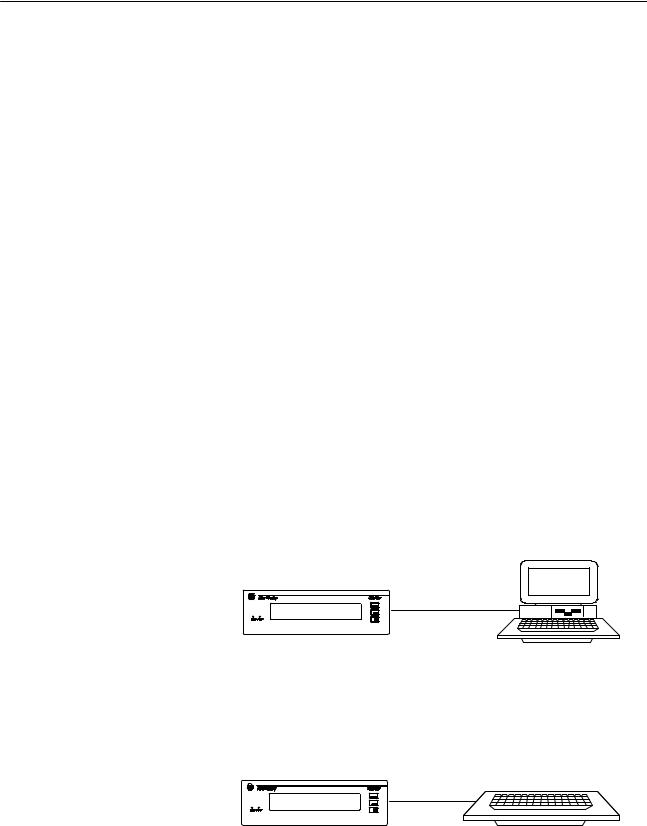
The DL40 Plus supports two methods for managing message files (messages and the attributes that control the display).
Offline Programmer
To use the programmer you connect a personal computer to the DL40 Plus. See publication 2706-6.2 for details on how to use the Offline Programming Software.
Offline Programmer
Computer
RS±232
DL40 Plus
2706±NC13 Cable
Onboard Editor
Use the Onboard Editor with an optional keyboard and front panel push buttons.
Onboard Editor
PC Keyboard
DL40 Plus
2±2 |
Using the Onboard Editor to Create Messages |
Entering the
Onboard Editor
Exiting the Onboard Editor
You must enter the Onboard Editor from Run mode or Help mode. Press [CTRL] [E] to enter the Onboard Editor.
Use the menu tree on the next page as a guide to onboard editing.
•Press [Y][ ] to access a function.
•Press [N][ ] to go to the next function.
•Press [Space Bar] to select or toggle through options with multiple choices.
•After toggling through all the functions in a level, entering [N][ ] returns you to the first function on that level.
Pressing [ESC] returns you to the previous menu level. You can exit the Onboard Editor at any time by pressing [ESC] one, two, three, or four times depending on the current level of the editor.
A complete list of Onboard Editor commands is listed on the inside back cover of this manual.
Exit the Onboard Editor in one of two ways:
•To exit and save your work, press [F10], then press [ESC] three times to return to Run mode.
•To exit without saving any changes, press [ESC], answer [Y][ ] to the confirmation request, then press [ESC] three more times. You will not be asked to confirm your decision if you have not made any to the message.
Publication 2706-6.1

Using the Onboard Editor to Create Messages |
2±3 |
Onboard Editor Menu
The following diagram provides an overview of the Onboard Editor's menu structure.
RUN MODE
[CTRL][E] |
|
|
|
|
|
|
|
|
|
Messages? |
No |
|
|
|
|
|
|
|
|
|
|
|
|
|
|
|
|
|
|
Yes |
|
|
Options? |
No |
|
|
|
|
|
|
|
|
|
|
|
|
|
||
|
|
|
|
|
|
|
|
|
|
Edit |
No |
|
Yes |
|
|
Triggering |
No |
Return to |
Yes |
Messages? |
|
|
|
|
|
||||
|
|
|
|
|
|
Port Setup? |
Run Mode? |
|
|
|
|
|
Run Mode |
|
|
|
|
|
|
Yes |
Message |
No |
|
|
|
Yes |
|
No |
|
|
Attribute |
|
|
|
|
|
|||
|
|
|
|
|
|
|
|
|
|
Message |
Defaults? |
|
Newest |
|
|
Triggering |
|
|
|
|
|
|
|
|
|
|
|||
|
|
Message |
|
|
|
|
|
||
Number |
|
|
|
|
Port Setup |
|
|
|
|
Yes |
|
on Line 1 |
|
|
|
|
|
||
|
|
|
|
|
|
|
|
||
|
Display Line |
|
Autorun |
|
|
Message |
|
|
|
|
Scroll Message |
|
|
|
|
|
|
||
|
|
Message |
|
|
Format |
|
|
|
|
|
Print Message |
|
|
|
|
|
|
||
|
|
Number |
|
|
|
|
|
|
|
|
Send Msg to Slave |
|
|
|
|
|
|
|
|
|
|
|
|
|
Variable |
|
|
|
|
|
Wait Time for Msg |
|
Background |
|
|
|
|
|
|
|
Autoclear |
|
|
|
Format |
|
|
|
|
|
Autorepeat |
|
Message |
|
|
|
|
|
|
|
Chain Message |
|
Number |
|
|
[Ctrl] [W] |
|
|
|
|
Energize Relay |
|
|
|
|
Format |
|
|
|
|
Send Msg to Stack |
|
Special |
|
|
|
|
|
|
|
Send Time to Stack |
|
Message |
|
|
|
|
|
|
|
Hide Message |
|
Start |
|
|
|
|
|
|
|
Acknowledge Msg |
|
Number |
|
|
|
|
|
|
|
Slave Color |
|
|
|
|
|
|
|
|
|
Slave Length |
|
Message |
|
Parallel |
Remote I/O |
|
|
|
|
Slave Relay |
|
|
|
|
||||
|
|
|
Port Units |
Units |
|
|
|||
|
|
Delete |
Queueing |
|
|
|
|||
|
|
|
|
|
|
|
|
||
|
No |
Enable |
|
|
|
|
|
|
|
|
Messages? |
|
Use |
|
|
|
|
||
|
|
|
|
|
Bit Trigger |
|
|
||
|
|
|
|
|
High True |
|
|
|
|
|
|
|
|
|
|
Priority |
|
|
|
|
|
|
Time Format |
|
Logic |
|
|
|
|
|
|
|
|
|
Size |
|
|
||
|
|
Yes |
|
|
|
|
|
|
|
|
|
|
|
Using |
|
|
|
|
|
|
|
|
Language Set |
|
|
Always |
|
|
|
|
|
Message |
|
AC/DC |
|
|
|
||
|
|
|
|
|
|
|
|||
|
|
|
|
Converter |
|
Send |
|
|
|
|
|
Number |
|
|
|
|
|
||
|
|
|
|
|
|
Clock Data |
|
|
|
|
|
|
|
|
|
|
|
|
|
|
|
Yes |
|
No |
Data |
|
|
|
|
|
|
Exit & Save? |
Hold Time |
|
|
|
|
||
|
|
|
|
|
|
|
|
||
|
|
|
|
|
|
|
Publication 2706-6.1 |
|
|
2±4 |
Using the Onboard Editor to Create Messages |
Creating or Editing Messages Enter the MESSAGES function [Y][ ]. Enter the EDIT MESSAGES function [Y][ ]. Respond to the EDIT MSG prompt with a new message number to create a message or an existing message number to edit a message.
Note: FILE FREE gives you the number of kilobytes remaining in user Memory.
If there is no memory left, the DL40 Plus will display:
MESSAGE FILE IS FULL
PRESS ANY KEY
If your message exceeds 200 characters (including spaces) the DL40
Plus will display:
MAXIMUM LENGTH MSG
PRESS ANY KEY
Note: You must press the [F10] key to save any active message you are editing.
Publication 2706-6.1
Loading...