


 Loading...
PanelView Plus Compact Terminals
User Manual
Catalog Numbers 2711PC-K4M20D,
2711PC-B4C20D, 2711PC-T6M20D, 2711PCT6C20D, 2711PC-T10C4D1
Important User Information
Solid state equipment has operational characteristics differing from those of electromechanical equipment. Safety Guidelines for the Application, Installation and Maintenance of Solid State Controls (publication SGI-1.1 available from your local Rockwell Automation sales office or online at http://literature.rockwellautomation.com) describes some important differences between solid state equipment and hard-wired electromechanical devices. Because of this difference, and also because of the wide variety of uses for solid state equipment, all persons responsible for applying this equipment must satisfy themselves that each intended application of this equipment is acceptable.
In no event will Rockwell Automation, Inc. be responsible or liable for indirect or consequential damages resulting from the use or application of this equipment.
The examples and diagrams in this manual are included solely for illustrative purposes. Because of the many variables and requirements associated with any particular installation, Rockwell Automation, Inc. cannot assume responsibility or liability for actual use based on the examples and diagrams.
No patent liability is assumed by Rockwell Automation, Inc. with respect to use of information, circuits, equipment, or software described in this manual.
Reproduction of the contents of this manual, in whole or in part, without written permission of Rockwell Automation, Inc., is prohibited.
Throughout this manual, when necessary, we use notes to make you aware of safety considerations.
WARNING
Identifies information about practices or circumstances that can cause an explosion in a hazardous environment, which may lead to personal injury or death, property damage, or economic loss.
|
IMPORTANT |
|
Identifies information that is critical for successful application and understanding of the product. |
|||||
|
|
|
||||||
|
|
|
|
|
|
|
|
|
|
|
|
|
|
|
|
|
|
|
|
|
|
|
|
|
|
Identifies information about practices or circumstances that can lead to personal injury or death, |
|
ATTENTION |
|||||||
|
property damage, or economic loss. Attentions help you identify a hazard, avoid a hazard, and |
|||||||
|
|
|
|
|
|
|
|
|
|
|
|
|
|
|
|
|
recognize the consequence |
|
|
|
|
|
|
|||
|
|
|
|
|
|
|
||
|
|
|
|
|
|
|||
|
|
|
|
|
|
|
|
Labels may be on or inside the equipment, for example, a drive or motor, to alert people that |
SHOCK HAZARD |
||||||||
|
|
|
|
|
|
|
|
dangerous voltage may be present. |
|
|
|
|
|
||||
|
|
|
|
|
|
|
||
|
|
|
||||||
|
|
|
|
|
|
|
|
Labels may be on or inside the equipment, for example, a drive or motor, to alert people that |
|
BURN HAZARD |
|||||||
|
|
|
|
|
|
|
|
surfaces may reach dangerous temperatures. |
|
|
|
|
|
|
|
|
|
|
|
|
|
|
|
|
|
|
Allen-Bradley, PanelView Plus, PanelView Plus Compact, FactoryTalk View, FactoryTalk View ME, FactoryTalk View Studio, FactoryTalk ViewPoint, RSLinx Enterprise, Rockwell Automation, and TechConnect are trademarks of Rockwell Automation, Inc.
Trademarks not belonging to Rockwell Automation are property of their respective companies.

|
Table of Contents |
|
Preface |
Intended Audience . . . . . . . . . . . . . . . . . . . . . . . . . . . . . . . |
. 7 |
|
Parts List. . . . . . . . . . . . . . . . . . . . . . . . . . . . . . . . . . . . . . . . |
7 |
|
Additional Resources. . . . . . . . . . . . . . . . . . . . . . . . . . . . . . . |
7 |
|
Chapter 1 |
|
Overview |
Chapter Objectives . . . . . . . . . . . . . . . . . . . . . . . . . . . . . . . . |
9 |
|
Product Overview . . . . . . . . . . . . . . . . . . . . . . . . . . . . . . . . . |
9 |
|
Catalog Number Explanation . . . . . . . . . . . . . . . . . . . . . . . . . |
9 |
|
Software Support . . . . . . . . . . . . . . . . . . . . . . . . . . . . . . . . |
10 |
|
Hardware Configurations. . . . . . . . . . . . . . . . . . . . . . . . . . . |
10 |
|
Displays . . . . . . . . . . . . . . . . . . . . . . . . . . . . . . . . . . . . . . . |
11 |
|
Accessories . . . . . . . . . . . . . . . . . . . . . . . . . . . . . . . . . . . . . |
11 |
|
Chapter 2 |
|
Installing the Terminal |
Chapter Objectives . . . . . . . . . . . . . . . . . . . . . . . . . . . . . . . |
13 |
|
Hazardous Locations . . . . . . . . . . . . . . . . . . . . . . . . . . . . . . |
13 |
|
Environment and Enclosure. . . . . . . . . . . . . . . . . . . . . . . . . |
16 |
|
Required Tools . . . . . . . . . . . . . . . . . . . . . . . . . . . . . . . . . . |
17 |
|
Clearances . . . . . . . . . . . . . . . . . . . . . . . . . . . . . . . . . . . . . |
17 |
|
Cutout Dimensions . . . . . . . . . . . . . . . . . . . . . . . . . . . . . . . |
17 |
|
Mount the 400 or 600 Terminal in a Panel . . . . . . . . . . . . . . |
18 |
|
Mount the 1000 Terminal in a Panel. . . . . . . . . . . . . . . . . . . |
20 |
|
Product Dimensions . . . . . . . . . . . . . . . . . . . . . . . . . . . . . . |
22 |
|
Chapter 3 |
|
Connecting Power |
Chapter Objectives . . . . . . . . . . . . . . . . . . . . . . . . . . . . . . . |
23 |
|
Wiring and Safety Guidelines. . . . . . . . . . . . . . . . . . . . . . . . |
23 |
|
Removing and Installing the Power Terminal Block . . . . . . . |
24 |
|
Connecting Power. . . . . . . . . . . . . . . . . . . . . . . . . . . . . . . . |
26 |
|
Resetting the Terminals . . . . . . . . . . . . . . . . . . . . . . . . . . . . |
29 |
|
Chapter 4 |
|
Configuring the Terminal |
Chapter Objectives . . . . . . . . . . . . . . . . . . . . . . . . . . . . . . . |
31 |
|
Accessing Configuration Mode. . . . . . . . . . . . . . . . . . . . . . . |
31 |
|
Loading an Application . . . . . . . . . . . . . . . . . . . . . . . . . . . . |
35 |
|
Running an Application. . . . . . . . . . . . . . . . . . . . . . . . . . . . |
36 |
|
Application Settings. . . . . . . . . . . . . . . . . . . . . . . . . . . . . . . |
36 |
|
Terminal Settings . . . . . . . . . . . . . . . . . . . . . . . . . . . . . . . . |
36 |
|
Configuring Communication . . . . . . . . . . . . . . . . . . . . . . . . |
37 |
|
Configuring Network Information . . . . . . . . . . . . . . . . . . . . |
41 |
|
Configuring Diagnostics . . . . . . . . . . . . . . . . . . . . . . . . . . . |
45 |
|
Managing Files on the Terminal. . . . . . . . . . . . . . . . . . . . . . |
47 |
|
Modifying Display Settings . . . . . . . . . . . . . . . . . . . . . . . . . |
50 |
|
Font Linking . . . . . . . . . . . . . . . . . . . . . . . . . . . . . . . . . . . . |
53 |
|
Configuring the Keypad, Keyboard, or Mouse . . . . . . . . . . . |
54 |
Publication 2711PC-UM001A-EN-P - March 2009 |
3 |

Table of Contents |
|
|
|
Configuring the Touch Screen . . . . . . . . . . . . . . . . . . . . . . . |
56 |
|
Configuring Print Options . . . . . . . . . . . . . . . . . . . . . . . . . . |
58 |
|
Configuring Startup Options . . . . . . . . . . . . . . . . . . . . . . . . |
60 |
|
Configuring Startup Tests. . . . . . . . . . . . . . . . . . . . . . . . . . . |
63 |
|
Clearing the System Event Log. . . . . . . . . . . . . . . . . . . . . . . |
65 |
|
Displaying Terminal Information . . . . . . . . . . . . . . . . . . . . . |
66 |
|
Displaying |
|
|
FactoryTalk View ME Station Information. . . . . . . . . . . . . . . |
68 |
|
Modifying the Date, Time, or Time Zone . . . . . . . . . . . . . . . |
69 |
|
Modifying Regional Settings. . . . . . . . . . . . . . . . . . . . . . . . . |
71 |
|
Chapter 5 |
|
Installing and Replacing |
Chapter Objectives . . . . . . . . . . . . . . . . . . . . . . . . . . . . . . . |
75 |
Components |
Required Tools . . . . . . . . . . . . . . . . . . . . . . . . . . . . . . . . . . |
75 |
|
Precautions. . . . . . . . . . . . . . . . . . . . . . . . . . . . . . . . . . . . . |
75 |
|
Replacing the Battery . . . . . . . . . . . . . . . . . . . . . . . . . . . . . |
76 |
|
Replacing the Backlight. . . . . . . . . . . . . . . . . . . . . . . . . . . . |
79 |
|
Using an External CompactFlash Card . . . . . . . . . . . . . . . . . |
81 |
|
Removing the Product ID Label . . . . . . . . . . . . . . . . . . . . . . |
82 |
|
Replacing the Bezel. . . . . . . . . . . . . . . . . . . . . . . . . . . . . . . |
83 |
|
Cleaning the |
|
|
Display Window . . . . . . . . . . . . . . . . . . . . . . . . . . . . . . . . . |
85 |
|
Chapter 6 |
|
Terminal Connections |
Chapter Objectives . . . . . . . . . . . . . . . . . . . . . . . . . . . . . . . |
87 |
|
Cables for Runtime Communication . . . . . . . . . . . . . . . . . . . |
87 |
|
Communication Port Isolation . . . . . . . . . . . . . . . . . . . . . . . |
88 |
|
USB Ports . . . . . . . . . . . . . . . . . . . . . . . . . . . . . . . . . . . . . . |
89 |
|
Serial Connections. . . . . . . . . . . . . . . . . . . . . . . . . . . . . . . . |
90 |
|
Ethernet Connections . . . . . . . . . . . . . . . . . . . . . . . . . . . . . |
93 |
|
Chapter 7 |
|
Upgrading Firmware |
Chapter Objectives . . . . . . . . . . . . . . . . . . . . . . . . . . . . . . . |
95 |
|
Transferring Applications. . . . . . . . . . . . . . . . . . . . . . . . . . . |
95 |
|
Firmware Upgrade Wizard. . . . . . . . . . . . . . . . . . . . . . . . . . |
95 |
|
Preparing Terminal |
|
|
for Upgrade . . . . . . . . . . . . . . . . . . . . . . . . . . . . . . . . . . . . |
95 |
|
Upgrading Firmware with a CompactFlash Card . . . . . . . . . . |
96 |
|
Upgrading Firmware over a Network Connection . . . . . . . . |
100 |
4 |
Publication 2711PC-UM001A-EN-P - March 2009 |

|
|
Table of Contents |
|
Chapter 8 |
|
Troubleshooting |
Chapter Objectives . . . . . . . . . . . . . . . . . . . . . . . . . |
. . . . . 105 |
|
Status Indicators . . . . . . . . . . . . . . . . . . . . . . . . . . . |
. . . . . 105 |
|
Isolating the Problem . . . . . . . . . . . . . . . . . . . . . . . |
. . . . . 106 |
|
Startup Information Messages . . . . . . . . . . . . . . . . . |
. . . . . 108 |
|
Startup Sequence . . . . . . . . . . . . . . . . . . . . . . . . . . |
. . . . . 109 |
|
Startup Error Messages . . . . . . . . . . . . . . . . . . . . . . |
. . . . . 110 |
|
Checking Terminal Components . . . . . . . . . . . . . . . |
. . . . . 111 |
|
Ethernet Connection . . . . . . . . . . . . . . . . . . . . . . . . |
. . . . . 114 |
|
Hardware Compatibility. . . . . . . . . . . . . . . . . . . . . . |
. . . . . 115 |
|
Application Does Not Load . . . . . . . . . . . . . . . . . . . |
. . . . . 115 |
|
Application Does Not Run . . . . . . . . . . . . . . . . . . . . |
. . . . . 116 |
|
Configuration Mode Access . . . . . . . . . . . . . . . . . . . |
. . . . . 116 |
|
Appendix A |
|
Specifications |
Electrical. . . . . . . . . . . . . . . . . . . . . . . . . . . . . . . . . |
. . . . . 117 |
|
Environmental . . . . . . . . . . . . . . . . . . . . . . . . . . . . |
. . . . . 117 |
|
Display. . . . . . . . . . . . . . . . . . . . . . . . . . . . . . . . . . |
. . . . . 118 |
|
Mechanical . . . . . . . . . . . . . . . . . . . . . . . . . . . . . . . |
. . . . . 118 |
|
General . . . . . . . . . . . . . . . . . . . . . . . . . . . . . . . . . |
. . . . . 119 |
|
Agency Certifications. . . . . . . . . . . . . . . . . . . . . . . . |
. . . . . 119 |
|
Appendix B |
|
USB Devices |
Compatible USB Devices . . . . . . . . . . . . . . . . . . . . . |
. . . . . 121 |
|
Appendix C |
|
Available Fonts |
Download Fonts to Terminal . . . . . . . . . . . . . . . . . . |
. . . . . 123 |
|
Machine Edition Fonts CD . . . . . . . . . . . . . . . . . . . . |
. . . . . 124 |
Index |
. . . . . . . . . . . . . . . . . . . . . . . . . . . . . . . . . . . . . . . |
. . . . . 127 |
Publication 2711PC-UM001A-EN-P - March 2009 |
5 |

Table of Contents
6 |
Publication 2711PC-UM001A-EN-P - March 2009 |

Preface
Intended Audience
Parts List
Additional Resources
Use this manual if you are responsible for installing, configuring, and operating the PanelView Plus Compact terminals.
No special knowledge is required to understand this manual or operate the terminal. However, you must understand the functions and operations of the FactoryTalk View ME applications that will run on the terminal. Consult the application designer for this information.
Equipment installers must be familiar with standard panel installation techniques.
Your terminal is shipped with these items:
•Power terminal block
•FactoryTalk View ME runtime software preloaded
•Mounting levers or mounting clips (model dependent)
•Panel cutout template
•Installation instructions
The table lists resources available for the PanelView Plus terminals.
Resource |
Description |
|
|
PanelView Plus 400 and 600 Terminals |
Provides details on how to install the |
Installation Instructions, publication |
terminals in a panel, and wire power. |
2711P-IN002 |
|
|
|
PanelView Plus 700 to 1500 Terminals and |
Provides details on how to install the |
Display Modules, and PanelView Plus |
terminals in a panel, and wire power. |
Compact 1000 Terminals, Installation |
|
Instructions, publication 2711P-IN001 |
|
|
|
Wiring and Grounding Guidelines for |
Provides grounding and wiring guidelines |
PanelView Plus Devices Technical Data, |
for PanelView Plus terminals. |
publication 2711P-TD001 |
|
|
|
You can view or download publications at http://literature.rockwellautomation.com. To order paper copies of technical documentation, contact your local Rockwell Automation distributor or sales representative.
Publication 2711PC-UM001A-EN-P - March 2009 |
7 |

Preface
8 |
Publication 2711PC-UM001A-EN-P - March 2009 |

Chapter 1
Overview
Chapter Objectives
This chapter covers these topics:
•Product description
•Catalog number explanation
•Software support
•Terminal configurations
•Display modules
•Accessories
Product Overview
The PanelView Plus Compact terminals are similar to some PanelView Plus terminal configurations but with limited hardware and software functions. Major differences of the compact terminals include:
•Fixed hardware configuration, without the addition or replacement of modular components.
•Serial and Ethernet communication only.
•Connection to a single logic controller using either RSLinx Enterprise or KEPServer Enterprise software, not both.
•Limited number of displays and alarms in the FactoryTalk View Machine Edition (ME) application and runtime software.
•FactoryTalk ViewPoint software is not supported.
•Primary HMI for CompactLogix controllers.
|
Applications created for PanelView Plus Compact terminals are |
|
TIP |
||
referred to as Compact Machine Edition applications. You can |
||
|
||
|
||
|
run compact applications on PanelView Plus and PanelView |
|
|
Plus Compact terminals. You cannot run a regular Machine |
|
|
Edition application created for a PanelView Plus terminal on a |
|
|
PanelView Plus Compact terminal. |
Catalog Number
Explanation
The table provides catalog number configurations for the PanelView Plus Compact terminals.
Cat. No. |
Display Size |
Operator Input |
Display Type |
Input Power |
|
|
|
|
|
2711PC-K4M20D |
4 inch |
Keypad |
Monochrome |
|
|
|
|
|
|
2711PC-B4C20D |
Keypad and Touch |
Color |
|
|
|
|
|||
|
|
|
|
|
2711PC-T6M20D |
6 inch |
Touch |
Monochrome |
DC |
|
|
|
||
2711PC-T6C20D |
Color |
|
||
|
|
|
||
|
|
|
|
|
2711PC-T10C4D1 |
10 inch |
Touch |
Color |
|
|
|
|
|
|
Publication 2711PC-UM001A-EN-P - March 2009 |
9 |
Chapter 1 |
Overview |
|
|
Software Support
Each terminal is preloaded with FactoryTalk View Machine Edition runtime and configuration software that does not require activation. Applications for the compact terminals are created using FactoryTalk View Studio software.
Software Requirements |
Version |
|
|
FactoryTalk View Studio |
5.1 or later |
|
|
RSLinx Enterprise(1) |
5.20 or later |
(1)RSLinx Enterprise software is provided with FactoryTalk View Studio. During software installation, you are prompted to install RSLinx Enterprise software.
Compact Machine Edition applications are restricted to a subset of the functions allowed on the PanelView Plus terminals.
•Maximum of 25 displays
•Maximum of 200 alarm messages
•Maximum screen resolution of 640 x 480 (VGA)
•one connection or shortcut to a single controller using either RSLinx Enterprise 5.20 or KEPServer Enterprise.
•Serial and Ethernet communication only.
If using RSLinx Enterprise, only serial-DF1, serial-DH485 and Ethernet drivers are supported.
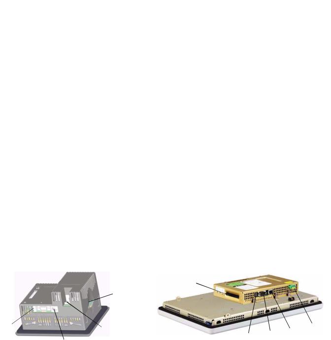
Hardware Configurations |
|
The terminal configurations are fixed and do not support |
|||||||
|
|
|
|
communication modules. The 1000 touch terminal has a fixed display |
|||||
|
|
|
|
module and logic module that cannot be replaced. |
|
|
|||
400 and 600 Configurations |
|
|
|
1000 Configuration |
|
|
|
||
|
|
|
|
|
5 |
|
|
|
|
|
|
|
5 |
|
|
|
|
|
|
1 |
|
|
4 |
|
|
|
|
4 |
|
|
|
|
|
|
|
||||
|
|
|
|
|
|
|
|||
|
|
|
|
|
|
2 |
3 |
|
|
|
|
|
|
|
1 |
|
|||
|
|
|
|
|
|
|
|||
|
|
3 |
|
|
|
|
|
||
2 |
|
|
|
|
|
|
|
||
|
|
|
|
|
|
|
|
|
|
|
|
|
|
Item |
|
Description |
|
|
|
|
|
|
|
|
|
|
|
|
|
|
|
|
|
1 |
|
USB port(1) |
|
|
|
|
|
|
2 |
|
RS-232 serial port |
|
|
|
|
|
|
|
|
|
|
|
|
|
|
|
|
|
3 |
|
10/100BaseT Ethernet port |
|
|
|
|
|
|
|
|
|
|
|
|
|
|
|
|
|
4 |
|
Power input, 24V DC |
|
|
|
|
|
|
|
|
|
|
|
|
|
|
|
|
|
5 |
|
CompactFlash Type 1 card slot |
|
|
|
|
|
|
|
|
|
|
|
|
|
|
(1) The 400 and 600 models have one USB port; the 1000 model have two USB ports.
10 |
Publication 2711PC-UM001A-EN-P - March 2009 |
Overview |
Chapter 1 |
|
|
Displays
The terminal configurations provide monochrome or color displays with keypad, touch, or keypad/touch input.
Accessories
Keypad Description of 400 Terminals
Keys |
Description |
|
|
|
|
F1 through F8 |
Programmable keys that initiate functions on terminal display. |
|
|
|
|
Numeric Keypad |
0…9, ., -, Backspace, Enter, Left and Right Tab keys, Shift keys |
|
|
|
|
Navigation Keys |
Use the arrow keys for navigation. |
|
|
Use the Alt+arrow keys to activate home, end, page up, and page |
|
|
down functions. |
|
|
|
|
|
|
|
ATTENTION |
Use a finger or gloved finger to operate the keypad. To operate |
|||
the touch screen, use your finger, gloved finger, or plastic stylus |
||||
|
|
|
||
|
|
|
||
|
|
|
with a minimum tip radius of 1.3 mm (0.051 in.). Using other |
|
|
|
|
object or tool may damage the touch screen or keypad. |
|
|
|
|
|
|
|
|
|
|
|
The compact terminals use many of the same accessories as the PanelView Plus terminals with the exception of the display modules, communication modules, logic modules, and memory.
|
The PanelView Plus Compact terminals do not support the |
|
IMPORTANT |
||
addition or replacement of modular components. |
||
|
||
|
||
|
||
Compact Flash Cards |
||
Cat. No. |
Description |
|
|
2711P-RC2 |
128 MB blank CompactFlash card |
|
|
2711P-RC3 |
256 MB blank CompactFlash card |
|
|
2711P-RC4 |
512 MB blank CompactFlash card |
|
|
2711P-RCH |
CompactFlash to PCMCIA adapter |
|
|
Backlight
Cat. No. |
Description |
|
|
2711P-RL10C2 |
Replacement color backlight for 1000 series B and C displays |
|
|
Publication 2711PC-UM001A-EN-P - March 2009 |
11 |

Chapter 1 |
Overview |
|
|
Replacement Bezels
Cat. No. |
|
Description |
||
|
|
|
|
|
2711P-RBT10 |
|
Replacement bezel for 1000 touch terminal |
||
|
|
|
|
|
Protective Antiglare Overlays |
||||
|
|
|
||
Cat. No. |
|
Description |
||
|
|
|
|
|
2711P-RGK4 |
|
Antiglare overlay (3) for PanelView Plus 400 keypad terminal |
||
|
|
|
|
|
2711P-RGB4 |
|
Antiglare overlay (3) for PanelView Plus 400 color keypad/touch terminal |
||
|
|
|
|
|
2711P-RGT6 |
|
Antiglare overlay (3) for PanelView Plus 600 touch terminal |
||
|
|
|
|
|
2711P-RGT6 |
|
Antiglare overlay (3) for PanelView Plus 600 touch terminal |
||
|
|
|
|
|
2711P-RGT10 |
|
Antiglare overlay (3) for PanelView Plus 1000 touch terminal |
||
|
|
|
|
|
Adapter Plates |
|
|
|
|
|
|
|
|
|
Cat. No. |
|
Description |
||
|
|
|
|
|
2711P-RAK4 |
|
Adapts a PanelView Plus 400 keypad terminal to a PanelView |
||
|
|
|
Standard 550 keypad cutout |
|
|
|
|
|
|
2711P-RAT10 |
|
Adapts a PanelView Plus 1000 touch terminal to a PanelView |
||
|
|
|
1000/1000E touch cutout |
|
|
|
|
|
|
Cables |
|
|
|
|
|
|
|
|
|
Cat. No. |
|
Description |
||
|
|
|
|
|
2711-NC13 |
|
RS-232 operating/programming cable (9-pin D-shell to 9-pin D-shell), 5 |
||
|
|
|
m (16.4 ft) |
|
|
|
|
|
|
2711-NC14 |
|
RS-232 operating/programming cable (9-pin D-shell to 9-pin D-shell), |
||
|
|
|
10 m (32.7 ft) |
|
|
|
|
|
|
2711-NC17 |
|
Remote RS-232 serial cable (9-pin D-shell to 9-pin D-shell) |
||
|
|
|
|
|
2711-NC21 |
|
RS-232 operating cable (9-pin D-shell to 8-pin mini DIN), 5 m (16.4 ft) |
||
|
|
|
|
|
2711-NC22 |
|
RS-232 operating cable (9-pin D-shell to 8-pin mini DIN), 10 m (32.7 ft) |
||
|
|
|
||
2711P-CBL-EX04 |
Ethernet CAT5 crossover cable, industrial grade, 4.3 m (14 ft) |
|||
|
|
|
||
Communication Adapters |
||||
|
|
|
|
|
Cat. No. |
|
Description |
||
|
|
|
|
|
1761-NET-AIC |
|
AIC+ advanced interface converter |
||
|
|
|
|
|
Miscellaneous |
|
|
|
|
|
|
|
|
|
Cat. No. |
|
Description |
||
|
|
|
|
|
2711P-RY2032 |
|
Replacement battery for 1000 terminal |
||
|
|
|
|
|
2711P-RTMC |
|
Replacement mounting clips for 1000 terminals, quantity of 8 |
||
|
|
|
|
|
2711P-RTFC |
|
Replacement mounting levers for 400 and 600 terminals, quantity of 8 |
||
|
|
|
|
|
2711-TBDC |
|
Replacement DC power terminal block for 400 and 600 terminals |
||
|
|
|
|
|
2711P-RTBDC2 |
|
Replacement two-position DC power terminal block for 1000 terminal |
||
|
|
|
|
|
12 |
Publication 2711PC-UM001A-EN-P - March 2009 |
Chapter 2
Chapter Objectives
Hazardous Locations
Installing the Terminal
This chapter provides pre-installation information and procedures on how to install the terminals.
•Hazardous locations
•Environment and enclosure
•Required tools
•Clearances
•Panel cutout dimensions
•Mount the 400 or 600 terminal in a panel
•Mount the 1000 terminal in a panel
•Product dimensions
This equipment is suitable for these locations:
•Class I, Division 2, Groups A, B, C, D
•Class II, Division 2, Groups F, G
•Class III
•ordinary, nonhazardous locations
The following statement applies to use in hazardous locations.
Explosion Hazard
WARNING
• Substitution of components may impair suitability for hazardous locations.
• Do not disconnect equipment unless power has been switched off and area is known to be nonhazardous.
•Do not connect or disconnect components unless power has been switched off.
•All wiring must comply with N.E.C. articles 501, 502, 503, and/or C.E.C. section 18-1J2 as appropriate.
•Peripheral equipment must be suitable for the location in which it is used.
The terminals have a temperature code of T4 when operating in a 55 °C (131 °F) maximum ambient temperature. Do not install the terminals in environments where atmospheric gases have ignition temperatures less than 135 °C (275 °F).
Publication 2711PC-UM001A-EN-P - March 2009 |
13 |

Chapter 2 Installing the Terminal
USB Ports
The PanelView Plus Compact terminals contain universal serial bus (USB) ports that comply with hazardous location environments. This section details the field-wiring compliance requirements and is provided in accordance with the National Electrical Code, article 500.
PanelView Plus Compact Terminals Control Drawing
Associated Nonincendive Field Wiring Apparatus
PanelView Plus 400, 600, or 1000 Host Product |
Nonincendive Field |
|
Wiring Apparatus |
||
|
||
Nonincendive Field Wiring |
USB |
|
Peripheral |
||
USB Port |
Device |
|
|
Table 1 - PanelView Plus Compact USB Port Circuit Parameters
|
|
|
|
Ca |
|
La |
||
Display Size |
Voc |
Isc |
|
|
|
|
|
|
Groups |
|
Groups |
Groups |
|
Groups |
|||
|
|
|
A and B |
|
C and D |
A and B |
|
C and D |
|
|
|
|
|
|
|
|
|
400 and 600 |
5.25V DC |
1.68 A |
10 µF |
|
10 µF |
3.5 µH |
|
15 µH |
Series C or later |
|
|
|
|
|
|
|
|
|
|
|
|
|
|
|
|
|
1000 |
5.25V DC |
1.68 A |
10 µF |
|
10 µF |
15 µH |
|
15 µH |
|
|
|
|
|
|
|
|
|
Selected nonincendive field wiring apparatus must have nonincendive circuit parameters conforming with Table 2.
Table 2 - Required Circuit Parameters for the USB Peripheral Device
Vmax |
≥ |
Voc |
Imax |
≥ |
Isc |
Ci + Ccable |
£ |
Ca |
Li + Lcable |
£ |
La |
14 |
Publication 2711PC-UM001A-EN-P - March 2009 |

Installing the Terminal |
Chapter 2 |
|
|
Application Information
Per the National Electrical Code the circuit parameters of nonincendive field wiring apparatus for use in hazardous locations shall be coordinated with the associated nonincendive field wiring apparatus such that their combination remains nonincendive. The PanelView Plus terminal and the USB peripheral device shall be treated in this manner.
The circuit parameters of the PanelView Plus terminal USB port are given in Table 1. The USB peripheral device and its associated cabling shall have circuit parameters with the limits given in Table 2 for them to remain nonincendive when used with the PanelView Plus terminal USB port. If cable capacitance and inductance are not known the following values from ANSI/ISA-RP 12.06.01-2003 may be used:
Ccable = 197 pF/m (60 pF/ft)
Lcable = 0.7 µH/m (0.20 µH/ft)
Nonincendive field wiring must be wired and separated in accordance with 501.10(B)(3) of the National Electrical Code (NEC) ANSI/NFPA 70 or other local codes as applicable.
This associated nonincendive field wiring apparatus has not been evaluated for use in combination with another associated nonincendive field wiring apparatus.
Symbol Definitions
Voc |
Open circuit voltage of the host USB port. |
Isc |
Maximum output current of the host USB port. |
Vmax |
Maximum applied voltage rating of the USB peripheral device. |
|
Vmax shall be greater than or equal to Voc in Table 1. (Vmax ≥ Voc ). |
Imax |
Maximum current to which the USB peripheral device can be subjected. |
|
Imax shall be greater than or equal to Isc in Table 1. (Imax ≥ Isc). |
Ci |
Maximum internal capacitance of the USB peripheral device. |
Ca |
Maximum allowed capacitance of the USB peripheral device and its |
|
associated cable. The sum of Ci of the USB peripheral device and Ccable of |
|
the associated cable shall be less than or equal to Ca . (Ci + Ccable ≤ Ca). |
Li |
Maximum internal inductance of the USB peripheral device. |
La |
Maximum allowed inductance of the USB peripheral device and its |
|
associated cable. The sum of Li of the USB peripheral device and Lcable of |
|
the associated cable shall be less than or equal to La . (Li + Lcable ≤ La). |
Publication 2711PC-UM001A-EN-P - March 2009 |
15 |
Chapter 2 Installing the Terminal
Environment and Enclosure
ATTENTION
This equipment is intended for use in a Pollution Degree 2 industrial environment, in overvoltage Category II applications (as defined in IEC 60664-1), at altitudes up to 2000 m (6561 ft) without derating.
The terminals are intended for use with programmable logic controllers. Terminals that are AC powered must also be connected to the secondary of an isolating transformer.
This equipment is considered Group 1, Class A industrial equipment according to IEC CISPR 11. Without appropriate precautions, there may be difficulties ensuring electromagnetic compatibility in residential and other environments due to conducted or radiated disturbances.
This equipment is supplied as open-type equipment. It must be mounted within an enclosure that is suitably designed for those specific environmental conditions that will be present and appropriately designed to prevent personal injury resulting from accessibility to live parts. The interior of the enclosure must be accessible only by the use of a tool. The terminals meet specified NEMA Type and IEC ratings only when mounted in a panel or enclosure with the equivalent rating. Subsequent sections of this publication may contain additional information regarding specific enclosure type ratings that are required to comply with certain product safety certifications.
In addition to this publication, see:
•Industrial Automation Wiring and Grounding Guidelines, publication 1770-4.1, for additional installation requirements.
•NEMA Standards 250 and IEC 60529, as applicable, for explanations of the degrees of protection provided by different types of enclosure.
16 |
Publication 2711PC-UM001A-EN-P - March 2009 |

Installing the Terminal |
Chapter 2 |
|
|
Required Tools
Clearances
Cutout Dimensions
These tools are required for panel installation:
•Panel cutout tools
•Small, slotted screwdriver
•Torque wrench (lb•in) for tightening the mounting clips on the 1000 terminal
Allow adequate clearance around the terminal, inside the enclosure, for adequate ventilation. Consider heat produced by other devices in the enclosure. The ambient temperature around the terminals must be between 0…55 °C (32…131 ºF).
Clearance Area |
400 and 600 Terminals |
1000 Terminal |
|
|
|
Top |
51 mm (2 in.) |
51 mm (2 in.) |
|
|
|
Bottom |
102 mm (4 in.) |
51 mm (2 in.) |
|
|
|
Side(1) |
25 mm (1 in.) |
25 mm (1 in.) |
Back |
None |
25 mm (1 in.) |
|
|
|
(1) Minimum side clearance for insertion of memory card and cable wiring is 102 mm (4 in.).
Use the full size template shipped with your terminal to mark the cutout dimensions.
Terminal Type |
Height mm (in.) |
Width mm (in.) |
|||
|
|
|
|
|
|
400 |
Keypad, or Keypad and Touch |
123 |
(4.86) |
156 |
(6.15) |
|
|
|
|
|
|
600 |
Touch |
123 |
(4.86) |
156 |
(6.15) |
|
|
|
|
|
|
1000 Touch |
224 |
(8.8) |
305 |
(12.00) |
|
|
|
|
|
|
|
Publication 2711PC-UM001A-EN-P - March 2009 |
17 |
Chapter 2 Installing the Terminal
Mount the 400 or 600 Terminal in a Panel
Mounting levers secure the terminal to the panel. The number of levers you use (4 or 6) varies by terminal type.
ATTENTION |
Disconnect all electrical power from the panel before making |
|||
the panel cutout. |
||||
|
|
|
||
|
|
|
||
|
|
|
Make sure the area around the panel cutout is clear. |
|
|
|
|
Take precautions so metal cuttings do not enter any |
|
|
|
|
||
|
|
|
||
|
|
|
components already installed in the panel. |
|
|
|
|
Failure to follow these warnings may result in personal injury or |
|
|
|
|
damage to panel components. |
|
|
|
|
|
|
Follow these steps to mount the 400 or 600 terminals in a panel.
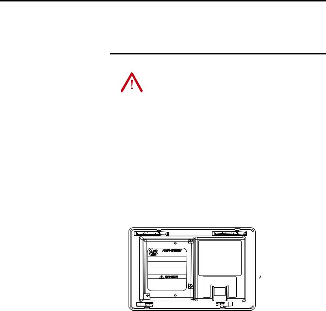
1.Cut an opening in the panel by using the panel cutout shipped with the terminal.
2.Make sure the terminal sealing gasket is properly positioned on the terminal.
This gasket forms a compression-type seal. Do not use sealing compounds.

 Sealing Gasket
3.Place the terminal in the panel cutout.
If installing the terminal in an existing 550 panel cutout, align the terminal with the center of the cutout for best gasket sealing.
4.Insert all mounting levers into the mounting slots on the terminal.
18 |
Publication 2711PC-UM001A-EN-P - March 2009 |

Installing the Terminal |
Chapter 2 |
|
|
Slide each lever until the flat side of the lever touches the surface of the panel.
Mounting Slots |
Flat Side of Lever |
Mounting Levers |
||||
|
|
|
|
|
|
|
|
|
|
|
|
|
|
5.When all levers are in place, slide each lever an additional notch or two until you hear a click.
6.Rotate each lever in the direction indicated until it is in the final latch position.
Follow the latching sequence for the optimum terminal fit.
6  1
1
Notch
Alignment Marks Rotate lever until notch in lever aligns with proper alignment mark on terminal.
1 |
4 |
|
4 Levers |
3 |
2 |
1 |
5 |
3 |
|
6 Levers |
|
4 |
2 |
6 |
|
|
|
Use this table as a guide to provide an adequate gasket seal between the terminal and the panel.
|
|
|
|
Lever Position |
Panel Thickness Range |
Typical Gauge |
|
|
|
1 |
1 |
1.52…2.01 mm (0.060…0.079 in.) |
16 |
6 5 4 |
3 |
2 |
2 |
2.03…2.64 mm (0.08…0.104 in.) |
14 |
|
|
|
|
||||
|
|
|
|
3 |
2.67…3.15 mm (0.105…0.124 in.) |
12 |
Terminal Markings |
4 |
3.17…3.66 mm (0.125…0.144 in.) |
10 |
|||
or Alignment |
|
|
5 |
3.68…4.16 mm (0.145…0.164 in.) |
8/9 |
|
|
|
|
|
|||
|
|
|
|
6 |
4.19…4.75 mm (0.165…0.187 in.) |
7 |
ATTENTION |
Follow instructions to provide a proper seal and to |
|||
prevent potential damage to the product. Rockwell |
||||
|
|
|
||
|
|
|
||
|
|
|
Automation assumes no responsibility for water or |
|
|
|
|
chemical damage to the terminal or other equipment |
|
|
|
|
within the enclosure because of improper installation. |
|
|
|
|
|
|
Publication 2711PC-UM001A-EN-P - March 2009 |
19 |

Chapter 2 Installing the Terminal
Mount the 1000 Terminal in
a Panel
Mounting clips secure the terminal to the panel.
ATTENTION |
Disconnect all electrical power from the panel before making |
|||
the panel cutout. |
||||
|
|
|
||
|
|
|
||
|
|
|
Make sure the area around the panel cutout is clear. |
|
|
|
|
Take precautions so metal cuttings do not enter any |
|
|
|
|
||
|
|
|
||
|
|
|
components already installed in the panel. |
|
|
|
|
Failure to follow these warnings may result in personal injury or |
|
|
|
|
damage to panel components. |
|
|
|
|
|
|
Follow these steps to mount the terminal in a panel.
1.Cut an opening in the panel by using the panel cutout shipped with the terminal.
2.Make sure the terminal sealing gasket is properly positioned on the terminal.
This gasket forms a compression-type seal. Do not use sealing compounds.
 Sealing Gasket
3. Place the terminal in the panel cutout.
20 |
Publication 2711PC-UM001A-EN-P - March 2009 |
Installing the Terminal |
Chapter 2 |
|
|
4. Slide the ends of the mounting clips into the slots on terminal.
Mounting Clip
Mounting Clip Slot
5.Tighten the mounting clip screws by hand until the gasket seal contacts the mounting surface uniformly.
6.Tighten the mounting clips screws to a torque of 0.90…1.1 N•m (8…10 lb•in) by using the specified sequence, making sure not to overtighten.
1 |
4 |
|
Torque Sequence |
3 |
2 |
|
|
ATTENTION |
Tighten the mounting clips to the specified torque to |
|||
provide a proper seal and to prevent damage to the |
||||
|
|
|
||
|
|
|
||
|
|
|
product. Allen-Bradley assumes no responsibility for |
|
|
|
|
water or chemical damage to the product or other |
|
|
|
|
equipment within the enclosure because of improper |
|
|
|
|
installation. |
|
|
|
|
|
|
Publication 2711PC-UM001A-EN-P - March 2009 |
21 |
Chapter 2 Installing the Terminal
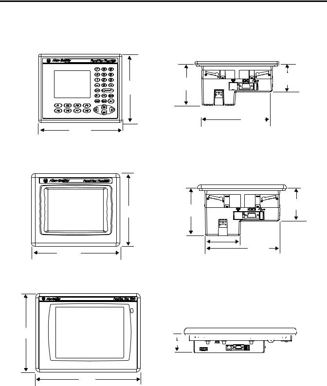
Product Dimensions
Product dimensions for each terminal are in mm (in.).
PanelView Plus 400 Keypad or Keypad/Touch Dimensions
|
90 |
60 |
|
152 |
(2.35) |
||
(3.54) |
|||
|
|||
(6.0) |
|
||
|
|
 71 (2.81)

154 (6.08)
185 (7.28)
PanelView Plus Compact 600 Touch Dimensions
68 (2.68)
152 (6.0) |
98 (3.86) |
|
|
|
71 (2.81) |
185 (7.28) |
154 (6.08) |
|
PanelView Plus Compact 1000 Touch Dimensions
248
(9.7) 
 55 (2.18)


329
(12.97)
22 |
Publication 2711PC-UM001A-EN-P - March 2009 |

Chapter 3
Chapter Objectives
Wiring and Safety
Guidelines
Connecting Power
This chapter covers wiring and safety guidelines, and provides procedures to:
•remove and install the power terminal block.
•connect DC power.
•reset the terminal.
Use publication NFPA 70E Electrical Safety Requirements for Employee Workplaces, IEC 60364 Electrical Installations in Buildings, or other applicable wiring safety requirements for the country of installation when wiring the devices. In addition to the NFPA guidelines:
•connect the device and other similar electronic equipment to its own branch circuit.
•protect the input power by a fuse or circuit breaker rated at no more than 15 A.
•route incoming power to the device by a separate path from the communication lines.
•cross power and communication lines at right angles if they must cross.
•Communication lines can be installed in the same conduit as low-level DC I/O lines (less than 10V).
•shield and ground cables appropriately to avoid electromagnetic interference (EMI).
•Grounding minimizes noise from EMI and is a safety measure in electrical installations.
For more information on grounding recommendations, refer to the National Electrical Code published by the National Fire Protection Association.
For more information, refer to Wiring and Grounding Guidelines for PanelView Plus Devices, publication 2711P-TD001. You can locate this publication in the literature library at this website http://literature.rockwellautomation.com.
Publication 2711PC-UM001A-EN-P - March 2009 |
23 |

Chapter 3 Connecting Power
Removing and Installing the
Power Terminal Block
The terminals are shipped with the power terminal block installed. You can remove the terminal block for ease of installation, wiring, and maintenance.
Explosion Hazard
WARNING
Substitution of components may impair suitability for hazardous locations.
Do not disconnect equipment unless power has been switched off and area is known to be nonhazardous.
Do not connect or disconnect components unless power has been switched off.
All wiring must comply with N.E.C. articles 501, 502, 503, and/or C.E.C. section 18-1J2 as appropriate.
Peripheral equipment must be suitable for the location in which it is used.
PanelView Plus Compact 400 and 600 Terminals
ATTENTION |
Do not force terminal blocks into connectors to prevent |
|
potential damage to terminal. |
||
|
Follows these steps to remove the terminal block in the PanelView 400 and 600 terminals.
1.Insert the tip of small, flat-blade, screwdriver into the terminal block access slot.
2.Gently pry the terminal block away from terminal to release the locking mechanism.
24 |
Publication 2711PC-UM001A-EN-P - March 2009 |

Connecting Power |
Chapter 3 |
|
|
Follow these steps to replace the terminal block.
1.Press the terminal block base in first with block leaning outward.
2.Gently push the top of the terminal block back to the vertical position to snap in locking tab.
PanelView Plus Compact 1000 Terminals
Follow these steps to remove the terminal block.
1.Loosen the two screws that secure the terminal block.
2.Gently pull the terminal block away from the connector.
GND
Follow these steps to install the terminal block.
1.Reattach the terminal block to the connector until seated.
2.Tighten the two screws that secure the terminal block to the connector.
Publication 2711PC-UM001A-EN-P - March 2009 |
25 |

Chapter 3 Connecting Power
Connecting Power
The PanelView Plus Compact terminals have an integrated, 24V DC power supply. See Appendix A, Specifications for power ratings.
The power supply is internally protected against reverse polarity of the DC+ and DCconnections. Connecting DC+ or DCto the earth terminal may damage the device.
The input power terminal block supports these wire sizes.
Wire Specifications for DC Input Power Terminal Block
Terminal |
Wire Type |
Dual-wire Gauge(1) |
Single-wire Gauge |
Terminal Screw Torque |
||
400 and 600 |
Stranded |
Cu 90 °C (194 °F) |
22…16 AWG |
22…14 AWG |
0.45…0.56 N•m (4…5 lb•in) |
|
|
or solid |
|
||||
1000 |
0.56 N•m (5 lb•in) |
|||||
|
|
|
||||
|
|
|
|
|
|
|
(1) Two-wire max. per terminal.
External Power Supply For Non-insolated DC Terminals
TIP |
The PanelView Plus Compact terminals contain non-isolated DC |
|
power supplies. |
||
|
||
|
Use a single, 24V DC power supply to power each PanelView Plus Compact terminal, such as cat. no. 2711P-RSACDIN. Using a separate, isolated and ungrounded source to power each terminal prevents ground loop currents from damaging the terminals.
Multiple AC Power Supplies to Power Multiple DC Terminals
L2 |
L1 |
|
L2 |
L1 |
|
AC/DC Power Supply
(2711P-RSACDIN)
dc+ dc-
AC/DC Power Supply
(2711P-RSACDIN)
dc+ dc-
|
|
|
|
|
|
|
|
|
|
|
Circuitry |
|
|
|
Circuitry |
|
|
||
|
|
|
|
|
|
|
|
|
|
|
|
|
|
|
|
|
|
|
|
|
|
|
|
|
|
|
|
|
|
PanelView Plus |
PanelView Plus |
|
|
The output on the power supply must be isolated from the input and not connected to earth/ground.
The non-isolated power supply does not provide galvanic isolation. A Class 2 or Safety Extra-Low Voltage (SELV) isolated power supply with a 24V DC nominal output voltage is required to power the terminal.
ATTENTION |
Use a Class 2 or SELV supply as required by local wiring codes |
|||
for your installation. The Class 2 and SELV power sources |
||||
|
|
|
||
|
|
|
||
|
|
|
provide protection so that under normal and single-fault |
|
|
|
|
conditions, the voltage between the conductors, and between |
|
|
|
|
the conductors and functional earth or protective earth does not |
|
|
|
|
exceed a safe value. |
|
|
|
|
|
|
26 |
Publication 2711PC-UM001A-EN-P - March 2009 |

Connecting Power |
Chapter 3 |
|
|
Earth/Ground Connection
You must connect the earth/ground terminal to a low-impedance earth/ground.
•The 1000 terminals have the earth/ground connection on the rear of the display module.
•The 400 and 600 terminals have the functional earth/ground connection on the power input terminal block.
|
The earth/ground connection to ground is mandatory. This |
|
IMPORTANT |
||
connection is required for noise immunity, reliability, and |
||
|
||
|
||
|
Electromagnetic Compliance (EMC) with the European Union |
|
|
(EU) EMC directive for CE-mark conformance and is required for |
|
|
safety by Underwriters Laboratory. |
|
|
|
The earth terminal requires a minimum wire gauge.
Earth Wire Specifications
Terminal |
Symbol |
Wire Type |
Wire Gauge |
Terminal Screw Torque |
||
|
|
|
|
|
|
|
400 and 600 |
|
|
|
14…12 AWG |
0.45…0.56 N•m (4…5 lb•in) |
|
|
|
|
|
|||
|
|
Stranded or solid |
Cu 90 °C (194 °F) |
|
|
|
1000 |
GND |
14…10 AWG |
1.13…1.36 N•m (10…12 lb•in) |
|||
|
|
|||||
|
|
|
|
|||
|
|
|
|
|
||
|
|
|
|
|
|
|
On most PanelView Plus DC terminals, the earth/ground terminal is internally connected to the DCterminal within the product.
ATTENTION |
Damage or malfunction can occur when a voltage potential |
||
|
|
|
exists between two separate ground points. Make sure the |
|
|
|
|
|
|
|
terminal does not serve as a conductive path between ground |
|
|
|
points at different potentials. |
|
|
|
|
|
|
|
|
The PanelView Plus terminals have isolated and nonisolated communication ports. Refer to Communication Port Isolation page 88 for details.
|
For more information, refer to Wiring and Grounding Guidelines |
|
IMPORTANT |
||
for PanelView Plus Devices, publication 2711P-TD001. |
||
|
||
|
||
|
|
Publication 2711PC-UM001A-EN-P - March 2009 |
27 |
Chapter 3 Connecting Power
1000 DC Terminal
GND
Earth/Ground to Ground Bus GND
GND
Connect DC Power
WARNING
Explosion Hazard - Do not disconnect equipment unless power has been switched off and area is known to be nonhazardous.
Disconnect all power before installing or replacing components. Failure to disconnect power may result in electrical shock or damage to the terminal.
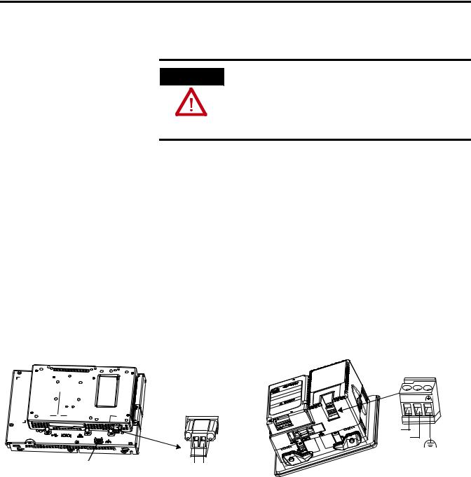
Follow these steps to connect the terminal to DC power.
1.Verify that the terminal is not connected to a power source.
2.Secure the DC power wires to the terminal block.
Follow the markings on terminal blocks and terminal for proper connections.
3.Secure the earth/ground wire.
•On 400 and 600 terminals, secure the earth/ground wire to the functional earth/ground terminal on the input power terminal block.
•On the 1000 terminal, secure the earth/ground wire to the earth/ground terminal screw at the bottom of the display.
400 and 600 DC Terminals
|
+ |
– |
Terminal Block |
|
|
– + |
DC + |
|
|
|
|
|
DC - |
|
|
|
Functional Earth |
DC - DC + |
|
to Ground Bus |
4. Apply 24V DC power to the terminal.
28 |
Publication 2711PC-UM001A-EN-P - March 2009 |

Connecting Power |
Chapter 3 |
|
|
Resetting the Terminals
Use the reset switch to restart a terminal without having to disconnect and reapply power. After a reset, the terminal performs a series of startup tests and then either:
•runs the .MER application loaded in the terminal.
•enters Configuration mode.
The action that occurs depends on the startup options configured for your terminal. Refer to page 60 for information on startup options.
Refer to Chapter 8, Troubleshooting , for a list of startup information and error messages.
Reset
Reset Switch
•On 400 and 600 terminals, press the reset switch with your finger or a nonconductive object.
•On 1000 terminals, insert a thin, nonconductive probe into the hole marked reset and press the switch.
ATTENTION |
Use a nonconductive object to press the reset or default switch. |
|||
Do not use a conducting object such as a paper clip or you may |
||||
|
|
|
||
|
|
|
||
|
|
|
damage the terminal. Do not use the tip of a pencil; graphite |
|
|
|
|
may damage the terminal. |
|
|
|
|
|
|
|
|
|
|
|
Publication 2711PC-UM001A-EN-P - March 2009 |
29 |

Chapter 3 Connecting Power
30 |
Publication 2711PC-UM001A-EN-P - March 2009 |
Loading...