


440R-MSR42
Table of contents
 Loading...
MSR42 Control Module
User Manual
Important User Information
Because of the variety of uses for the products described in this publication, those responsible for the
application and use of this control equipment must satisfy themselves that all necessary steps have been
taken to assure that each application and use meets all performance and safety requirements, including
any applicable laws, regulations, codes and standards.
Reproduction of the contents of this copyrighted publication, in whole or part, without written permission
of Rockwell Automation, is prohibited.
Throughout this manual we use notes to make you aware of safety considerations:
The illustrations, charts, sample programs and layout examples shown in the guide are intended solely for
purposes of example. Since there are many variables and requirements associated with any particular
installation, Rockwell Automation does not assume responsibility or liability (to include intellectual property
liability) for actual use based upon the examples shown in this publication.
Rockwell Automation publication SGI-1.1, Safety Guidelines for the Application, Installation and
Maintenance of Solid-State Control (available from your local Rockwell Automation sales oce), describes
some important dierences between solid-state equipment and electromechanical devices that should be
taken into consideration when applying products such as those described in this publication.
It is recommended that you save this user manual for future use.
Identies information about practices or circumstances that can cause an explosion in
a hazardous environment, which may lead to personal injury or death, property
damage, or economic loss.
Identies information that is critical for successful application and understanding of
the product.
Identies information about practices or circumstances that can lead to personal
injury or death, property damage, or economic loss. Attentions help you identify a
hazard, avoid a hazard, and recognize the consequences.
SHOCK HAZARD
Labels may be on or inside the equipment (for example, drive or motor) to alert people
that dangerous voltage may be present.
BURN HAZARD
Labels may be on or inside the equipment (for example, drive or motor) to alert people
that surfaces may reach dangerous temperatures.
WARNING
IMPORTANT
ATTENTION

MSR42 Control Module User Manual
Main module
Expansion modules
Content
Approvals and Conformity . . . . . . . . . . . . . . . . . . . . . . . . . 1
Introduction . . . . . . . . . . . . . . . . . . . . . . . . . . . . . . . . . . . . . . 1
Special features . . . . . . . . . . . . . . . . . . . . . . . . . . . . . . . . . . . . . . . . . . . . . . 2
Customer Configurations . . . . . . . . . . . . . . . . . . . . . . . . . . . . . . . . . . . . 2
Applications . . . . . . . . . . . . . . . . . . . . . . . . . . . . . . . . . . . . . . 2
Typical applications . . . . . . . . . . . . . . . . . . . . . . . . . . . . . . . . . . . . . . . . . . 2
Application restrictions . . . . . . . . . . . . . . . . . . . . . . . . . . . . . . . . . . . . . . 2
Dimensions . . . . . . . . . . . . . . . . . . . . . . . . . . . . . . . . . . . . . . . 2
Wiring diagrams . . . . . . . . . . . . . . . . . . . . . . . . . . . . . . . . . . 2
Basic configuration . . . . . . . . . . . . . . . . . . . . . . . . . . . . . . . . . . . . . . . . . . 2
Customer Configurations . . . . . . . . . . . . . . . . . . . . . . . . . . . . . . . . . . . . 3
Status outputs . . . . . . . . . . . . . . . . . . . . . . . . . . . . . . . . . . . . 4
LED display elements . . . . . . . . . . . . . . . . . . . . . . . . . . . . . . 4
Response time . . . . . . . . . . . . . . . . . . . . . . . . . . . . . . . . . . . . 4
General . . . . . . . . . . . . . . . . . . . . . . . . . . . . . . . . . . . . . . . . . . . . . . . . . . . . . 4
Micro 400 safety light curtain . . . . . . . . . . . . . . . . . . . . . . . . . . . . . . . . 5
Other safety components connected to GPIO terminals . . . . . . . . 5
MSR45E relay expansion module . . . . . . . . . . . . . . . . . . . . . . . . . . . . . 5
Basic configuration . . . . . . . . . . . . . . . . . . . . . . . . . . . . . . . . . . . . . . . . . . 5
Installation . . . . . . . . . . . . . . . . . . . . . . . . . . . . . . . . . . . . . . . 5
Mounting location . . . . . . . . . . . . . . . . . . . . . . . . . . . . . . . . . . . . . . . . . . . 5
Cable and wires . . . . . . . . . . . . . . . . . . . . . . . . . . . . . . . . . . . . . . . . . . . . . 5
Supply voltage . . . . . . . . . . . . . . . . . . . . . . . . . . . . . . . . . . . . . . . . . . . . . . . 5
Earth connection . . . . . . . . . . . . . . . . . . . . . . . . . . . . . . . . . . . . . . . . . . . . 6
Micro400 light curtain . . . . . . . . . . . . . . . . . . . . . . . . . . . . . . . . . . . . . . . 6
Start mode . . . . . . . . . . . . . . . . . . . . . . . . . . . . . . . . . . . . . . . . . . . . . . . . . . 6
Minimum off time . . . . . . . . . . . . . . . . . . . . . . . . . . . . . . . . . . . . . . . . . . . 6
EDM or start release . . . . . . . . . . . . . . . . . . . . . . . . . . . . . . . . . . . . . . . . . 6
Safety Components . . . . . . . . . . . . . . . . . . . . . . . . . . . . . . . . . . . . . . . . . . 7
Safety Override . . . . . . . . . . . . . . . . . . . . . . . . . . . . . . . . . . . . . . . . . . . . . . 7
OSSD connections . . . . . . . . . . . . . . . . . . . . . . . . . . . . . . . . . . . . . . . . . . 8
Muting . . . . . . . . . . . . . . . . . . . . . . . . . . . . . . . . . . . . . . . . . . . . . . . . . . . . . 8
Blanking . . . . . . . . . . . . . . . . . . . . . . . . . . . . . . . . . . . . . . . . . . . . . . . . . . . . 8
Blanking Teach-In . . . . . . . . . . . . . . . . . . . . . . . . . . . . . . . . . . . . . . . . . . . 9
Single Scan Filter . . . . . . . . . . . . . . . . . . . . . . . . . . . . . . . . . . . . . . . . . . . . 9
Testing the MSR42 . . . . . . . . . . . . . . . . . . . . . . . . . . . . . . . . . . . . . . . . . . 9
Te ch n ical Data . . . . . . . . . . . . . . . . . . . . . . . . . . . . . . . . . . .12
Appendix . . . . . . . . . . . . . . . . . . . . . . . . . . . . . . . . . . . . . . . .13
Interrupt Ignore Time . . . . . . . . . . . . . . . . . . . . . . . . . . . . . . . . . . . . . . 13
EC Declaration of Conformity . . . . . . . . . . . . . . . . . . . . . .15
Approvals and Conformity
The CE-declaration as well as the safety approval, performed by TÜV
Rheinland GmbH are available online at www.ab.com. The actual list of
relevant safety data and applied standards is given in these documents.
MSR42 units can only achieve their
function as a safety control module, if the
instructions in these manual and
accompanying documents are followed
and all laws and regulations are observed
at the time of installation.
Should these instructions not be carefully
followed, serious injury or death may
occur. The installer or system integrator
has full responsibility for a safe
integration of this product.
This instruction manual is part of the
MSR45E expander module. It must be
kept accessible together with the other
machine documentation during its entire
life cycle for all personnel responsible for
assembly, installation, operation and
maintenance.
Introduction
The MSR4x is a family of extremely compact safety controller modules.
The main controlling module allows for the connection and control of
the compact Allen-Bradley GuardShield Micro400 safety light curtain.
Depending on the configuration, other safety components can also be
connected and monitored simultaneously.
Diagnostic . . . . . . . . . . . . . . . . . . . . . . . . . . . . . . . . . . . . . . .10
External faults . . . . . . . . . . . . . . . . . . . . . . . . . . . . . . . . . . . . . . . . . . . . . .10
Internal faults . . . . . . . . . . . . . . . . . . . . . . . . . . . . . . . . . . . . . . . . . . . . . .10
Selection tables . . . . . . . . . . . . . . . . . . . . . . . . . . . . . . . . . .11
Accessories / Components . . . . . . . . . . . . . . . . . . . . . . . .11
Inspection and service . . . . . . . . . . . . . . . . . . . . . . . . . . . .12
Inspections . . . . . . . . . . . . . . . . . . . . . . . . . . . . . . . . . . . . . . . . . . . . . . . . . 12
Decommissioning . . . . . . . . . . . . . . . . . . . . . . . . . . . . . . . . . . . . . . . . . . 12
Product labels . . . . . . . . . . . . . . . . . . . . . . . . . . . . . . . . . . .12
Original instructions
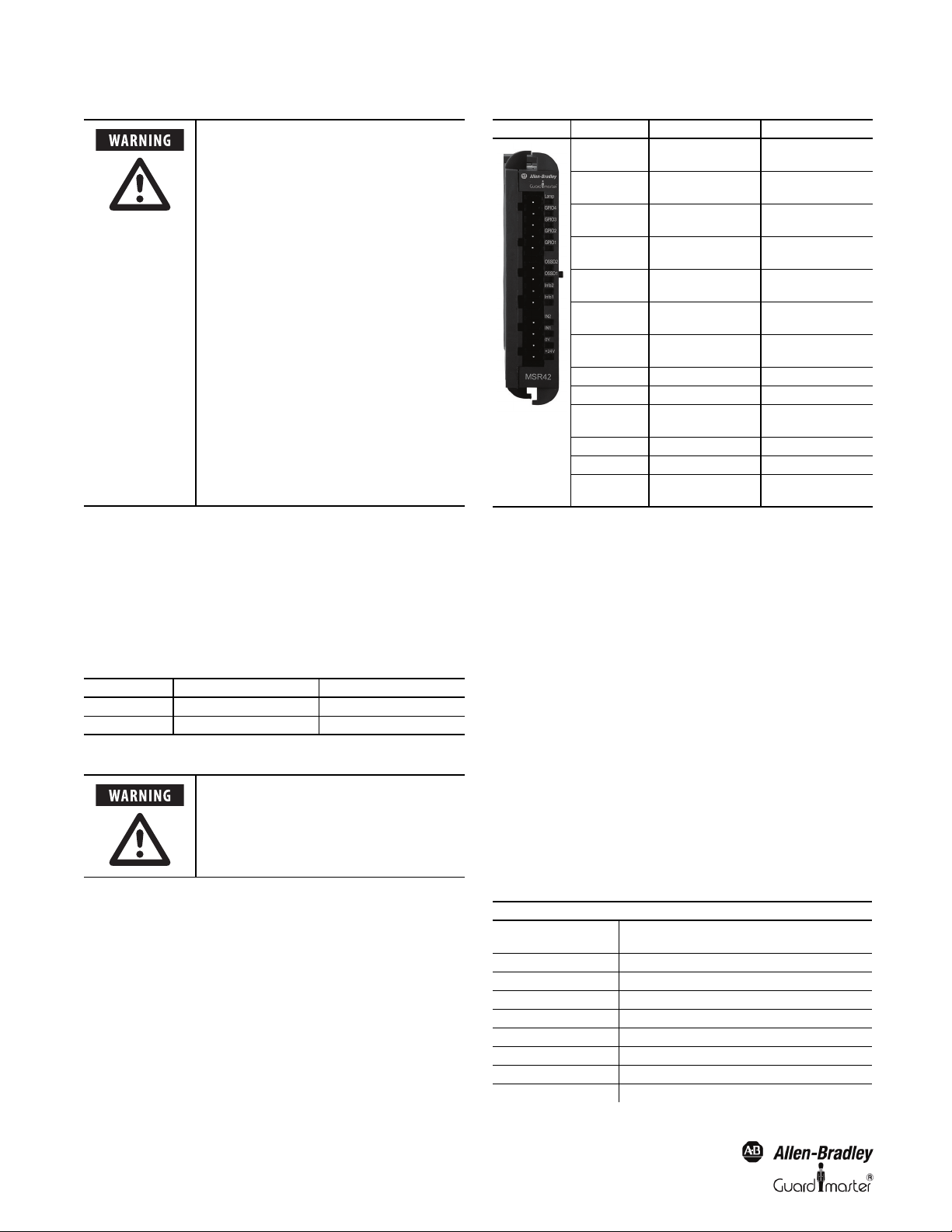
Figure 1: MSR42 controller with some safety components which can be connected
(depending on individual configuration)
Either the MSR41 or 42 offers two safety PNP outputs. Extension
modules are available for applications which need relay contact outputs.
1
Light Curtain Multi-Function Control Module User Manual
Up to three expander modules can be easy attached & controlled by the
base module.
In addition to the multifunction controllers, models are offered in special
configurations which are described in the appendix at the end of this
manual.
Special features
The characteristics of the MSR42 base module:
• Category 4, PLe according to EN ISO 13849-1
• Type 4 according to EN61496-1 / -2
• SIL CL3 according to EN62061
• SIL3 based on IEC 61508
• Short response times
•Expandable
• Up to 3 safety relay expander modules per base module
• Adjustable stop delay time
• Different safety components suitable for connection
•Blanking
•Muting
• Single scan selectable
Customer Configurations
The configuration of a MSR42 base module may very easily be adapted
to the customer requirements of an individual application with the help
of the USB/optical interface and the Allen-Bradley Guardmaster
Software “Configuration & Diagnostic Tool”. More information can be
found in the Software Technical Manual. The software is capable of
generating a configuration control document which lists configurations
and specifications of the controller and light curtain (Figure 16).
• Automatic storage facilities
Application restrictions
MSR42 base modules are not intended for application in explosive (EX)
or in radioactive environments.
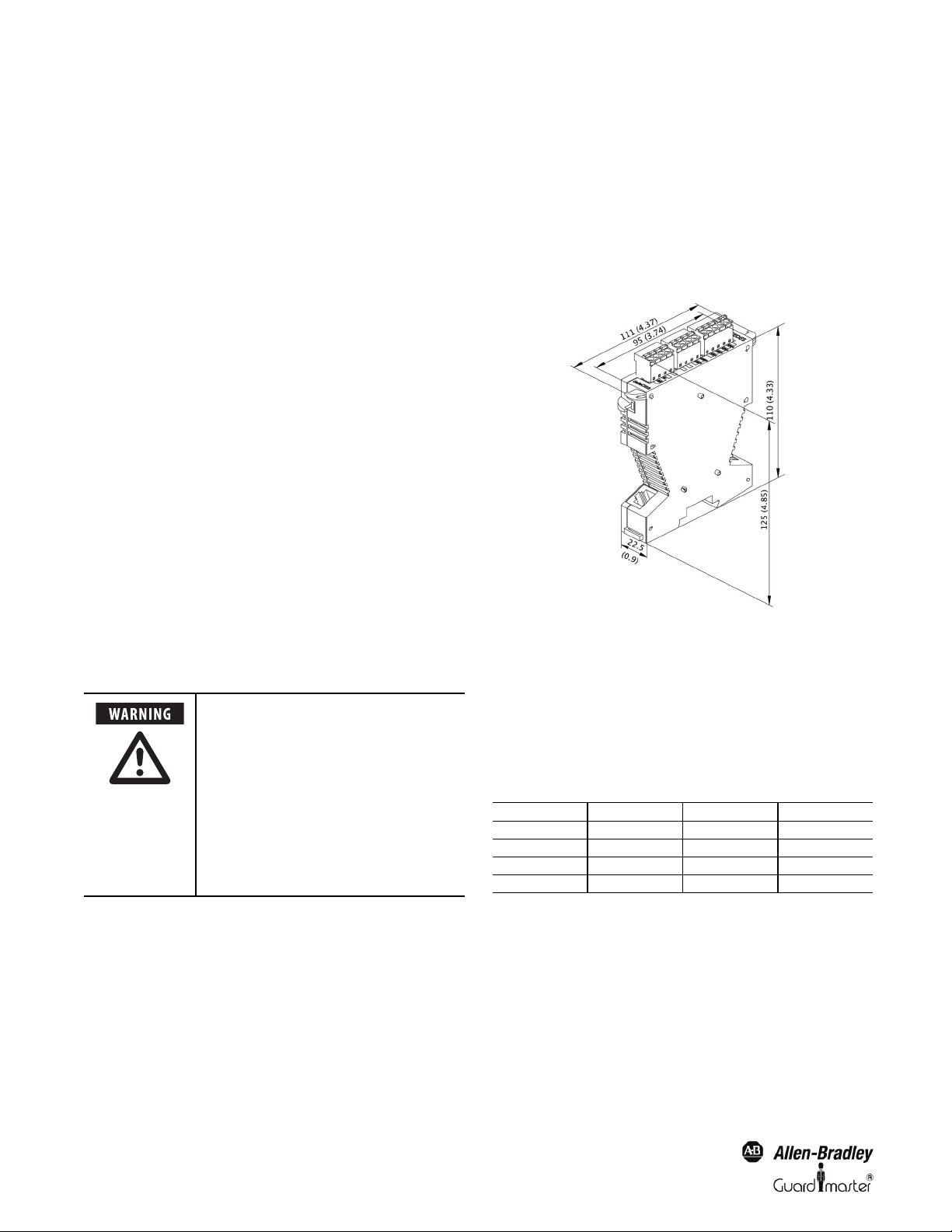
Dimensions
The dimensions of the MSR42 housing are illustrated in Figure 2.
Figure 2: Base module dimensions are the same for expansion modules
Wiring diagrams
The resolution and the response time may
increase due downloading other
configuration settings for the Micro 400
and other safety sensors connected to
MSR42. Consider the relevant resolution
and the maximum response time when
evaluating the safety distance. See
Chapter 7. All relevant data of the actual
configuration are always described in the
actual configuration control document
for that controller. Make sure that the
actual document is always stored near to
the control unit.
Applications
Typical applications
Typical MSR42 base module applications are:
•Presses
• Robotic cells with automatic insertion
•Assembly lines
• Indexing tables
• Conveyor systems
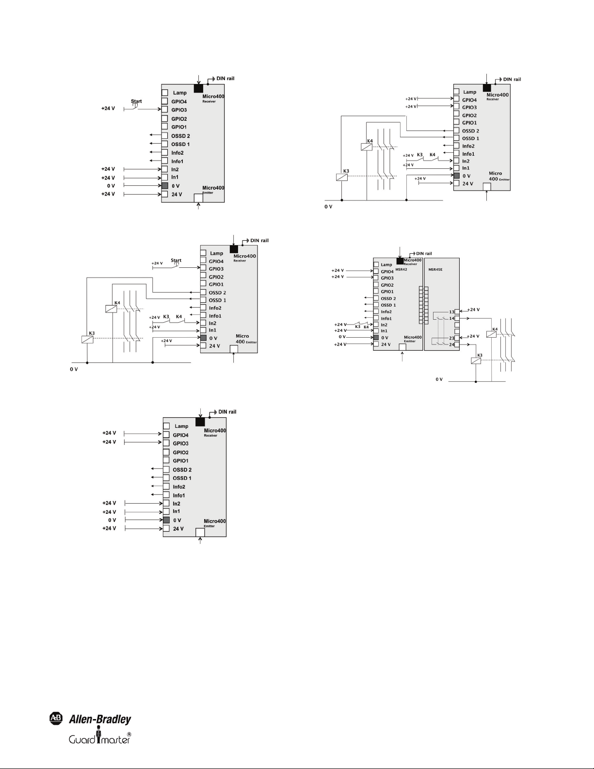
Basic configuration
The following figures show the connection possibilities for the MSR42
base module with the basic configuration. The logic of this basic version
is exemplified in the accompanying configuration control document:
Figure Safety component Start mode Start release
Figure 3 Micro400 manual no
Figure 4 Micro400 manual yes
Figure 5 Micro400 automat ic no
Figure 6 Micro400 automat ic yes
2
Original instructions
MSR42 Control Module User Manual
Figure 3: MSR42 base module (basic configuration, manual start) ). For teach-in see page 8
Figure 4: MSR42 base module (basic configuration, manual start, with start release).
For teach-in see page 8
Figure 5: MSR42 base module (basic configuration, automatic start). For teach-in see page 8
Figure 6: MSR42 base module (basic configuration, automatic start, with start release).
For teach-in see page 8
Figure 7: MSR42 base module and MSR45E expander module (basic configuration,
automatic start, with start release). For teach-in see page 8
Customer Configurations
The configuration of a MSR42 control module is set up via of the USB/
optical interface and the Allen-Bradley GuardShield Software
“Configuration & Diagnostic Tool”. The configuration procedure can be
found in the Technical Description Manual. Configuration details can be
found in the specific configuration control document for the MSR42.
The following features may be selected:
•Stop delay
• Single scan for faster response times
• Configuring GPIO terminals for one or two safety inputs
• Configuring GPIO terminals for E-Stop or door switch
•Safety Override
•Muting
•Blanking
A new configuration has to be downloaded to the MSR42 controller by
authorized personnel using the USB/optical interface (445L-AF6150).
Original instructions
3
Light Curtain Multi-Function Control Module User Manual
If authorized personnel reconfigure the
control module using the USB/optical
interface, then depending on the
configuration the response time or the
stop delay time t(delay) may increase. So
it is very important that after every new
configuration.
a. the configuration change label
(page 13) is placed on the control
module and
b. the new response time is confirmed to
be within the limits given by the risk
analysis of the machine and
c. All relevant data of the actual
configuration are always described in
the actual configuration control
document for that controller. Make
sure that the actual document is
always stored near to the control unit.
d. Using the blanking mode, the
resolution of the Micro 400 will be
reduced. Label the Micro 400 with the
new resolution. A label is supplied
with the Micro 400 light curtain
mounting kit.
Status outputs
The MSR42 base module has two status outputs (“Info1” and “Info2”).
The logic of these two outputs depends on the configuration. A
description of these outputs is given in the configuration control
document. The following table shows the logic of the two status outputs
for the basic configuration. The state of the status outputs will also be
displayed through LED, visible on the front side of the main module.
Terminal (LED) Output "high" (+24 V) Output "low" (0 V)
Info1 (LED) Start ok (green) No start possible (red)
Info2 (LED) System okay (green) Error (Lock out) (red)
Tab le 1
These outputs may not perform any
safety relevant functions. They are
diagnostic outputs which provide status
to a machine controller.
LED Signal / Color /Status Signal / Color /Status
Lamp
GPIO4
GPIO3
GPIO2
GPIO1
OSSD2
OSSD1
Info2 (LED) See page 4 See page 4
Info1 (LED) See page 4 See page 4
IN2
IN 1 +24 V / green / no test 0 V / red / test
0 V - -
+24 V
Orange / muting or blanking
activated
+24 V / green / automatic
start
+24 V / green / manual start
signal high or automatic start
+24 V / green / Teach-in
Blanking active
+24 V / green / Teach-in
Blanking active
+24 V / green / Micro 400 not
Activated
+24 V / green / Micro 400 not
Activated
+24 V / green / start release
okay
+24 V / green / power
connected
Off / muting or blanking not
activated
0 V / off / manual start
0 V / off / manual start
0 V / off / Teach-in Blanking
inactive
0 V / off / Teach-in Blanking
inactive
0 V / red / Micro 400 activated
(e.g. interrupted)
0 V / red / Micro 400 activated
(e.g. interrupted)
0 V / red / no start release
signal
0 V / off / no power
connected
Tab le 2
Response time
General
The response time of a MSR42 main module depends on the
configuration.
The relevant maximum response times for the MSR42 control module,
with respect to a specific Micro 400 light curtain and MSR45E expander
module, as well as a specific safety component may be calculated using
the formulas below.
The response time may be increased if a stop delay time t(delay) is
configured for a safety component or a Micro 400 light curtain. During
this delay, all start impulses are ignored. The safety outputs will switch
off at the end of this delay period.
The controlle r is sh ipped with th e double scan fi lter. Single s can filter ca n
be selected to reduce the response time. The relevant times may be found
in the corresponding configuration control document (e.g. see
configuration software manual).
LED display elements
Table 2 gives information about the LED on the front side of a MSR42
control unit with the basic configuration:
4
Original instructions
Term ino log y
t(C)
t(LC) Response time of the light curtain
t(delay) Stop delay time for the outputs
t(em) Response time for the MSR45E expansion module
t(GPIO) Evaluation time for the safety component (GPIO filter time)
t(SCext) Response time of the external safety component (e.g. Safe4)
t(totLCOSSD) Maximum OSSD response time triggered by the light curtain
t(totLCEXT) Maximum relay extension module response time for the light curtain
t(totSCOSSD) Maximum OSSD response time for the safety components on GPIO
Response time for the MSR42 control module (evaluation time),
without light curtain evaluation time
Loading...