


 Loading...
User Manual
PowerFlex 25-COMM-P PROFIBUS DPV1 Adapter

Important User Information
Solid-state equipment has operational characteristics differing from those of electromechanical equipment. Safety Guidelines for the Application, Installation and Maintenance of Solid State Controls (publication SGI-1.1 available from your local Rockwell Automation® sales office or online at http://www.rockwellautomation.com/literature/) describes some important differences between solid-state equipment and hard-wired electromechanical devices. Because of this difference, and also because of the wide variety of uses for solid-state equipment, all persons responsible for applying this equipment must satisfy themselves that each intended application of this equipment is acceptable.
In no event will Rockwell Automation, Inc. be responsible or liable for indirect or consequential damages resulting from the use or application of this equipment.
The examples and diagrams in this manual are included solely for illustrative purposes. Because of the many variables and requirements associated with any particular installation, Rockwell Automation, Inc. cannot assume responsibility or liability for actual use based on the examples and diagrams.
No patent liability is assumed by Rockwell Automation, Inc. with respect to use of information, circuits, equipment, or software described in this manual.
Reproduction of the contents of this manual, in whole or in part, without written permission of Rockwell Automation, Inc., is prohibited.
Throughout this manual, when necessary, we use notes to make you aware of safety considerations.
WARNING: Identifies information about practices or circumstances that can cause an explosion in a hazardous environment, which may lead to personal injury or death, property damage, or economic loss.
ATTENTION: Identifies information about practices or circumstances that can lead to personal injury or death, property damage, or economic loss. Attentions help you identify a hazard, avoid a hazard, and recognize the consequence.
SHOCK HAZARD: Labels may be on or inside the equipment, for example, a drive or motor, to alert people that dangerous voltage may be present.
BURN HAZARD: Labels may be on or inside the equipment, for example, a drive or motor, to alert people that surfaces may reach dangerous temperatures.
IMPORTANT Identifies information that is critical for successful application and understanding of the product.
Allen-Bradley, Rockwell Automation, Rockwell Software, PowerFlex, Studio 5000 and Connected Components Workbench are trademarks of Rockwell Automation, Inc.
Trademarks not belonging to Rockwell Automation are property of their respective companies.

|
Table of Contents |
|
|
Preface |
|
Overview |
Recommended Documentation . . . . . . . . . . . . . . . . . . . . . . . . . . . . . . . . . . . . |
5 |
|
Manual Conventions . . . . . . . . . . . . . . . . . . . . . . . . . . . . . . . . . . . . . . . . . . . . . . |
5 |
|
Chapter 1 |
|
Getting Started |
Components. . . . . . . . . . . . . . . . . . . . . . . . . . . . . . . . . . . . . . . . . . . . . . . . . . . . . . |
7 |
|
Features . . . . . . . . . . . . . . . . . . . . . . . . . . . . . . . . . . . . . . . . . . . . . . . . . . . . . . . . . . |
8 |
|
Understanding Parameter Types. . . . . . . . . . . . . . . . . . . . . . . . . . . . . . . . . . . . |
8 |
|
Compatible Products . . . . . . . . . . . . . . . . . . . . . . . . . . . . . . . . . . . . . . . . . . . . . . |
9 |
|
Required Equipment . . . . . . . . . . . . . . . . . . . . . . . . . . . . . . . . . . . . . . . . . . . . . . |
9 |
|
Safety Precautions . . . . . . . . . . . . . . . . . . . . . . . . . . . . . . . . . . . . . . . . . . . . . . . . |
10 |
|
Quick Start . . . . . . . . . . . . . . . . . . . . . . . . . . . . . . . . . . . . . . . . . . . . . . . . . . . . . . |
11 |
|
Chapter 2 |
|
Installing the Adapter |
Preparing for an Installation. . . . . . . . . . . . . . . . . . . . . . . . . . . . . . . . . . . . . . . |
13 |
|
Commissioning the Adapter . . . . . . . . . . . . . . . . . . . . . . . . . . . . . . . . . . . . . . |
13 |
|
Connecting the Adapter to the Drive . . . . . . . . . . . . . . . . . . . . . . . . . . . . . . |
15 |
|
Connecting the Adapter to the Network . . . . . . . . . . . . . . . . . . . . . . . . . . . |
18 |
|
Network Termination . . . . . . . . . . . . . . . . . . . . . . . . . . . . . . . . . . . . . . . . . . . . |
20 |
|
Applying Power . . . . . . . . . . . . . . . . . . . . . . . . . . . . . . . . . . . . . . . . . . . . . . . . . . |
20 |
|
Chapter 3 |
|
Configuring the Adapter |
Configuration Tools. . . . . . . . . . . . . . . . . . . . . . . . . . . . . . . . . . . . . . . . . . . . . . |
23 |
|
Using the Drive Keypad Interface to Access Parameters . . . . . . . . . . . . . |
23 |
|
Using the PowerFlex 4-Class HIM to Access Parameters. . . . . . . . . . . . . |
25 |
|
Setting the Node Address . . . . . . . . . . . . . . . . . . . . . . . . . . . . . . . . . . . . . . . . . |
25 |
|
Using Master-Slave Hierarchy (Optional) . . . . . . . . . . . . . . . . . . . . . . . . . . |
26 |
|
Setting a Fault Action . . . . . . . . . . . . . . . . . . . . . . . . . . . . . . . . . . . . . . . . . . . . |
27 |
|
Resetting the Adapter . . . . . . . . . . . . . . . . . . . . . . . . . . . . . . . . . . . . . . . . . . . . |
28 |
|
Restoring Adapter Parameters to Factory Defaults . . . . . . . . . . . . . . . . . . |
29 |
|
Viewing the Adapter Status Using Parameters . . . . . . . . . . . . . . . . . . . . . . |
29 |
|
Updating the Adapter Firmware. . . . . . . . . . . . . . . . . . . . . . . . . . . . . . . . . . . |
29 |
|
Chapter 4 |
|
Configuring the PROFIBUS Master |
Example Network . . . . . . . . . . . . . . . . . . . . . . . . . . . . . . . . . . . . . . . . . . . . . . . . |
31 |
|
Configuring the MVI69-PDPMV1 PROFIBUS DPV1 Master . . . . . . |
32 |
|
Installing GSD Files . . . . . . . . . . . . . . . . . . . . . . . . . . . . . . . . . . . . . . . . . . . . . . |
34 |
|
Configuring the Adapter as a Slave. . . . . . . . . . . . . . . . . . . . . . . . . . . . . . . . . |
36 |
|
Chapter 5 |
|
Using the I/O |
About I/O Messaging . . . . . . . . . . . . . . . . . . . . . . . . . . . . . . . . . . . . . . . . . . . . |
41 |
|
Understanding the I/O Image . . . . . . . . . . . . . . . . . . . . . . . . . . . . . . . . . . . . . |
42 |
|
Using Logic Command/Status . . . . . . . . . . . . . . . . . . . . . . . . . . . . . . . . . . . . |
42 |
Rockwell Automation Publication 520COM-UM004A-EN-E - November 2013 |
3 |

Table of Contents |
|
|
|
Using Reference/Feedback . . . . . . . . . . . . . . . . . . . . . . . . . . . . . . . . . . . . . . . . |
42 |
|
Using Datalinks . . . . . . . . . . . . . . . . . . . . . . . . . . . . . . . . . . . . . . . . . . . . . . . . . . |
43 |
|
I/O Communication . . . . . . . . . . . . . . . . . . . . . . . . . . . . . . . . . . . . . . . . . . . . . |
44 |
|
Chapter 6 |
|
Using Acyclic Messaging |
About Acyclic Messaging . . . . . . . . . . . . . . . . . . . . . . . . . . . . . . . . . . . . . . . . . |
47 |
|
Acyclic Messaging for DPV1 Class . . . . . . . . . . . . . . . . . . . . . . . . . . . . . . . . . |
49 |
|
Acyclic Messaging Examples. . . . . . . . . . . . . . . . . . . . . . . . . . . . . . . . . . . . . . . |
49 |
|
Chapter 7 |
|
Using Multi-Drive Mode |
Single-Drive Mode vs. Multi-Drive Mode . . . . . . . . . . . . . . . . . . . . . . . . . . |
55 |
|
System Wiring . . . . . . . . . . . . . . . . . . . . . . . . . . . . . . . . . . . . . . . . . . . . . . . . . . . |
57 |
|
Understanding the I/O Image . . . . . . . . . . . . . . . . . . . . . . . . . . . . . . . . . . . . . |
57 |
|
Configuring the RS-485 Network . . . . . . . . . . . . . . . . . . . . . . . . . . . . . . . . . |
58 |
|
Multi-Drive Ladder Logic Program for Generic Profile . . . . . . . . . . . . . . |
60 |
|
CompactLogix Controller Example. . . . . . . . . . . . . . . . . . . . . . . . . . . . . . . . |
61 |
|
Multi-Drive Mode Acyclic Messaging . . . . . . . . . . . . . . . . . . . . . . . . . . . . . . |
67 |
|
Additional Information. . . . . . . . . . . . . . . . . . . . . . . . . . . . . . . . . . . . . . . . . . . |
68 |
|
Chapter 8 |
|
Troubleshooting |
Understanding the Status Indicators . . . . . . . . . . . . . . . . . . . . . . . . . . . . . . . |
69 |
|
PORT Status Indicator . . . . . . . . . . . . . . . . . . . . . . . . . . . . . . . . . . . . . . . . . . . |
70 |
|
MOD Status Indicator. . . . . . . . . . . . . . . . . . . . . . . . . . . . . . . . . . . . . . . . . . . . |
70 |
|
NET A Status Indicator . . . . . . . . . . . . . . . . . . . . . . . . . . . . . . . . . . . . . . . . . . |
70 |
|
Viewing Adapter Diagnostic Items. . . . . . . . . . . . . . . . . . . . . . . . . . . . . . . . . |
71 |
|
Viewing and Clearing Events . . . . . . . . . . . . . . . . . . . . . . . . . . . . . . . . . . . . . . |
71 |
|
Appendix A |
|
Specifications |
Communications. . . . . . . . . . . . . . . . . . . . . . . . . . . . . . . . . . . . . . . . . . . . . . . . . |
75 |
|
Electrical . . . . . . . . . . . . . . . . . . . . . . . . . . . . . . . . . . . . . . . . . . . . . . . . . . . . . . . . |
75 |
|
Mechanical . . . . . . . . . . . . . . . . . . . . . . . . . . . . . . . . . . . . . . . . . . . . . . . . . . . . . . |
75 |
|
Environmental . . . . . . . . . . . . . . . . . . . . . . . . . . . . . . . . . . . . . . . . . . . . . . . . . . . |
75 |
|
Regulatory Compliance . . . . . . . . . . . . . . . . . . . . . . . . . . . . . . . . . . . . . . . . . . . |
75 |
|
Appendix B |
|
Adapter Parameters |
Device Parameters . . . . . . . . . . . . . . . . . . . . . . . . . . . . . . . . . . . . . . . . . . . . . . . . |
77 |
|
Appendix C |
|
Logic Command/Status Words: |
Logic Command Word . . . . . . . . . . . . . . . . . . . . . . . . . . . . . . . . . . . . . . . . . . . |
81 |
PowerFlex 520-Series Drives |
Logic Status Word . . . . . . . . . . . . . . . . . . . . . . . . . . . . . . . . . . . . . . . . . . . . . . . |
82 |
|
Glossary |
|
Index |
|
|
4 |
Rockwell Automation Publication 520COM-UM004A-EN-E - November 2013 |

Preface
Recommended
Documentation
Overview
For information on… |
See page… |
Recommended Documentation |
5 |
|
|
Manual Conventions |
5 |
|
|
All the recommended documentation listed in this section is available online at http://www.rockwellautomation.com/literature.
The following publications provide additional information:
For... |
See... |
Publication |
|
|
|
PROFIBUS |
PROFIBUS Standard |
http:// |
|
|
www.profibus.com/ |
|
PROFIBUS Installation Guideline |
|
|
|
|
|
|
|
|
Prosoft Configuration Builder |
http://www.prosoft- |
|
|
technology.com/ |
|
|
Products/ProSoft- |
|
|
Software/ProSoft- |
|
|
Configuration-Builder |
|
PROFIBUS DP-V1 Master Network Interface Module for |
http://www.prosoft- |
|
CompactLogix (Prosoft MVI69-PDPMV1) |
technology.com/ |
|
|
Products/Rockwell- |
|
Important: This manual does not cover all the steps required to |
Automation-In- |
|
chassis/Platform/ |
|
|
setup a PROFIBUS DP Master module. Make sure to see module’s |
|
|
CompactLogix/ |
|
|
user manual for detailed instructions. |
|
|
PROFIBUS-DP-V1- |
|
|
|
|
|
|
Master-Network- |
|
|
Interface-Module- |
|
|
for-CompactLogix |
PowerFlex®520-Series Drives |
PowerFlex 520-Series Adjustable Frequency AC Drive User Manual |
520-UM001 |
|
|
|
|
PowerFlex 520-Series AC Drive Specifications Technical Data |
520-TD001 |
|
|
|
|
PowerFlex 520-Series Communication Adapters Installation |
520COM-IN001 |
|
Instructions |
|
PowerFlex 4-Class HIM |
PowerFlex 4-Class Human HIM (DSI) Quick Reference |
22HIM-QR001 |
|
|
|
RSLogix™ 5000 |
RSLogix 5000 online help(1) |
– |
Connected Components |
Website containing information on the Connected Components |
http:// |
Workbench |
Workbench software tool, and includes a link for free software |
ab.rockwellautomatio |
|
download. |
n.com/ |
|
|
Programmable- |
|
|
Controllers/ |
|
|
Connected- |
|
|
Components- |
|
|
Workbench-Software |
|
Connected Components Workbench online help(1) |
– |
(1) The online help is installed with the software.
Manual Conventions
This manual provides information about the PowerFlex 25-COMM-P adapter and using it with PowerFlex 520-series drives for network communication.
Rockwell Automation Publication 520COM-UM004A-EN-E - November 2013 |
5 |

Preface Overview
The following conventions are used throughout this manual:
•Parameter names are shown in the format axxx [*]. The a represents the parameter group. The xxx represents the parameter number. The * represents the parameter name— for example C175 [DSI I/O Cfg].
•Menu commands are shown in bold type face and follow the format Menu > Command. For example, if you read “Select File > Open,” you should click the File menu and then click the Open command.
•RSLogix 5000 (version 20) was used for the screen captures in this manual. Different versions of the software may differ in appearance and procedures.
•The Studio 5000™ Engineering and Design Environment combines engineering and design elements into a common environment. The first element in the Studio 5000 environment is the Logix Designer application. The Logix Designer application is the rebranding of RSLogix 5000 software and will continue to be the product to program Logix 5000 controllers for discrete, process, batch, motion, safety, and drive-based solutions. The Studio 5000 environment is the foundation for the future of Rockwell Automation engineering design tools and capabilities. It is the one place for design engineers to develop all the elements of their control system.
6 |
Rockwell Automation Publication 520COM-UM004A-EN-E - November 2013 |

Chapter 1
Getting Started
Components
The 25-COMM-P adapter is intended for installation into a PowerFlex 520-series drive and is used for network communication.
Topic |
Page |
Components |
7 |
|
|
Features |
8 |
|
|
Understanding Parameter Types |
8 |
|
|
Compatible Products |
9 |
|
|
Required Equipment |
9 |
|
|
Safety Precautions |
10 |
|
|
Quick Start |
11 |
|
|
Components of the Adapter
25-COMM-P |
|
|
|
|
|
|
Item |
Part |
Description |
|
|
|
Node Address |
Switches for setting the node address of the |
|
|
|
switches |
adapter. See Setting the Endianness and |
|
|
|
|
Node Address Using the DIP Switches on |
|
|
|
|
page 14. |
|
|
Endianness Selection |
Sets the endianness of data transmitted over |
|
|
|
|
||
|
|
|
switch (Switch 8) |
network.See Setting the Endianness and |
|
|
|
|
Node Address Using the DIP Switches on |
|
|
|
|
page 14. |
|
|
|
Adapter-to-Drive |
A 40-pin, double-row shrouded female |
|
|
|
header |
header. An interface connector is used to |
|
|
|
|
connect this header to a header on the drive. |
|
|
|
Status indicators |
Three LEDs that indicate the status of the |
|
|
|
|
connected drive, adapter and network. See |
|
|
|
|
Troubleshooting on page 69. |
|
|
|
CS1/CS2 terminals |
Provides a clean ground for the |
|
|
|
communication bus cable shields. |
|
|
|
|
|
|
|
|
|
CS1 or CS2 should be connected to a clean |
|
|
|
|
|
ground or PE ground on the drive. |
|
|
|
PROFIBUS DB9 |
PROFIBUS connector for the PROFIBUS |
|
|
|
Female connector |
network cable. |
Rockwell Automation Publication 520COM-UM004A-EN-E - November 2013 |
7 |

Chapter 1 |
Getting Started |
|
|
Features
Understanding Parameter
Types
The features of the adapter include:
•Mounting onto a PowerFlex 520-series drive Control Module back cover for installation into the drive.
•Switches to set a node address before applying power to the PowerFlex drive. Alternatively, you can disable the switches and use parameters to configure these functions.
•Compatibility with various configuration tools to configure the adapter and host drive, including the following:
–PowerFlex 520-series drive built-in keypad
–PowerFlex 22-HIM-A3 or 22-HIM-C2S HIM (Human Interface Module)
–Connected Components Workbench (version 3 or greater)
–ControlFLASH software (version 7 or greater)
–Third-party PROFIBUS configuration software, such as Prosoft Configuration Builder
•Status indicators that report the status of the adapter and network communications.
•Parameter-configured 16-bit Datalinks in the I/O to meet application requirements (four Datalinks to write data and four Datalinks to read data).
•Acylic Messaging support.
•Master-Slave hierarchy that can be configured to transmit data to and from a controller on the network.
•Multi-drive mode which allows up to five drives to share a single PROFIBUS node.
•User-defined fault actions to determine how the adapter and its host PowerFlex 520-series drive respond to the following:
–I/O messaging communication disruptions (Comm Flt Action)
–Controllers in idle mode (Idle Flt Action)
This manual references two types of parameters:
•Device parameters are used to configure the adapter to operate on the network. These parameters reside on the adapter.
•Host parameters are used to configure the drive, including the datalink configuration for the datalinks used by the adapter. These parameters reside on the drive.
8 |
Rockwell Automation Publication 520COM-UM004A-EN-E - November 2013 |

Getting Started |
Chapter 1 |
|
|
You can view adapter Device parameters and Host parameters with any of the following drive configuration tools:
Compatible Products
•PowerFlex 520-series drive built-in keypad
•PowerFlex 22-HIM-A3 or 22-HIM-C2S HIM
•Connected Components Workbench software – click the tab for the adapter at the bottom of the window, and click the Parameters icon in the tool bar.
At the time of publication, the adapter is compatible with the following:
•PowerFlex 523 drives (all firmware revisions)
•PowerFlex 525 drives (all firmware revisions)
Required Equipment |
Equipment Shipped with the Adapter |
When you unpack the adapter, verify that the package includes the following:
One PowerFlex 25-COMM-P PROFIBUS DPV1 adapter
(installed in a PowerFlex 520-series drive control module back cover)
Two interface connectors
(one for connecting the adapter to PowerFlex 523 drives, one for connecting the adapter to PowerFlex 525 drives)
One Installation Instructions leaflet, publication 520COM-IN001
User-Supplied Equipment
The Device and Host parameters can be configured using the PowerFlex 520series drive built-in keypad (see Using the Drive Keypad Interface to Access Parameters on page 23). In addition, you must supply:
A small screwdriver
PROFIBUS cable; only use cable that conforms to PROFIBUS cable standards (Belden #3079A PROFIBUS cable or equivalent is recommended)
One 9-pin, male D-Sub PROFIBUS connector
PROFIBUS connectors are available from a variety of sources and in various sizes. As such, there may be mechanical limitations that prohibit the use of some connectors. Phoenix SUBCON-PLUS-PROFIB/AX/SC (Part # 2744380), Siemens 6GK1500-0FC00, or Brad BM5G60PP4Mxxx are recommended for use with PowerFlex 520-series drives.
Configuration tool, such as the following:
–PowerFlex 22-HIM-A3 or 22-HIM-C2S HIM
–Connected Components Workbench (version 3 or greater)
Connected Components Workbench is the recommended stand-alone software tool for use with PowerFlex drives. You can obtain a free copy by downloading it or requesting a DVD. Both options are available at http://ab.rockwellautomation.com/Programmable-Controllers/Connected-Components-Workbench-Software.
Controller configuration software RSLogix 5000 (version 20 or greater) or Logix Designer (version 21 or greater)
A computer connection to the PROFIBUS DPV1 network
Rockwell Automation Publication 520COM-UM004A-EN-E - November 2013 |
9 |
Chapter 1 |
Getting Started |
|
|
Safety Precautions
Please read the following safety precautions carefully.
ATTENTION: Risk of injury or death exists. The PowerFlex drive may contain high voltages that can cause injury or death. Remove all power from the PowerFlex drive, and then verify power has been removed before installing or removing an adapter.
ATTENTION: Risk of injury or equipment damage exists. Only personnel familiar with drive and power products and the associated machinery should plan or implement the installation, start up, configuration, and subsequent maintenance of the drive using this PROFIBUS adapter. Failure to comply may result in injury and/or equipment damage.
ATTENTION: Risk of equipment damage exists. The adapter contains ESD (Electrostatic Discharge) sensitive parts that can be damaged if you do not follow ESD control procedures. Static control precautions are required when handling the adapter. If you are unfamiliar with static control procedures, see Guarding Against Electrostatic Damage (publication 8000-4.5.2)
ATTENTION: Risk of injury or equipment damage exists. If the adapter is transmitting control I/O to the drive, the drive may fault when you reset the adapter. Determine how your drive will respond before resetting the adapter.
ATTENTION: Risk of injury or equipment damage exists. Device parameters
11 [Comm Flt Action] and 12 [Idle Flt Action] let you determine the action of the adapter and drive if I/O communication is disrupted or the controller is idle. By default, these parameters fault the drive. You may configure these parameters so that the drive continues to run, however, precautions should be taken to ensure that the settings of these parameters do not create a risk of injury or equipment damage. When commissioning the drive, verify that your system responds correctly to various situations (for example, a disconnected cable or a controller in idle state).
ATTENTION: Risk of injury or equipment damage exists. When a system is configured for the first time, there may be unintended or incorrect machine motion. Disconnect the motor from the machine or process during initial system testing.
ATTENTION: Risk of injury or equipment damage exists. The examples in this publication are intended solely for purposes of example. There are many variables and requirements with any application. Rockwell Automation, Inc. does not assume responsibility or liability (to include intellectual property liability) for actual use of the examples shown in this publication.
10 |
Rockwell Automation Publication 520COM-UM004A-EN-E - November 2013 |
Getting Started |
Chapter 1 |
|
|
Quick Start
This section is provided to help experienced users quickly start using the adapter. If you are unsure how to complete a step, refer to the referenced chapter.
Step |
Action |
See... |
|
|
|
|
|
1 |
Review the safety precautions for the adapter. |
Throughout this manual |
|
|
|
|
|
2 |
Verify that the PowerFlex drive is properly installed. |
PowerFlex 520-Series |
|
|
|
Adjustable Frequency AC |
|
|
|
Drive User Manual, |
|
|
|
publication 520-UM001 |
|
3 |
Commission the adapter. |
PowerFlex 520-Series |
|
|
Set a unique node address using the switches on the adapter. If desired, you can |
Communication Adapters |
|
|
disable the switches and use parameter settings instead. |
Installation Instructions, |
|
|
|
publication |
|
4 |
Install the adapter. |
||
520COM-IN001 and |
|||
|
Verify that the PowerFlex drive is not powered. Then, connect the adapter to the drive |
||
|
Chapter 2, |
||
|
using the appropriate interface connector (included with adapter). |
Installing the Adapter |
|
5 |
Connect the adapter to the PROFIBUS network. |
|
|
|
Verify that the PROFIBUS network is not powered. Then, connect the adapter to the |
|
|
|
network using a PROFIBUS cable. |
|
|
6 |
Apply power to the drive and to the network. |
|
|
|
The adapter receives power from the drive. |
|
|
|
a. Verify that the adapter is installed correctly and then apply power to the drive. |
|
|
|
The status indicators should be green. If they flash red, there is a problem. |
|
|
|
See Troubleshooting on page 69. |
|
|
|
b. Configure and verify key drive parameters. |
|
|
7 |
Configure the adapter for your application. |
Chapter 3, |
|
|
Set adapter parameters for the following functions as required by your application: |
Configuring the Adapter |
|
|
– Node address |
|
|
|
– I/O configuration |
|
|
|
– Master-Slave hierarchy |
|
|
|
– Fault actions |
|
|
8 |
Configure the PROFIBUS Master to communicate with the adapter. |
Chapter 4, |
|
|
Use controller configuration tools such as Prosoft Configuration Builder software for |
Configuring the |
|
|
PROFIBUS and RSLogix 5000 or Logix Designer software to configure the master on the |
PROFIBUS Master |
|
|
PROFIBUS network to recognize the adapter and drive. |
|
|
9 |
Configure the I/O. |
Chapter 5, |
|
|
Use a controller configuration tool such as RSLogix 5000 or Logix Designer software |
Using the I/O |
|
|
that enables you to control the adapter and connected drive using I/O. |
|
Rockwell Automation Publication 520COM-UM004A-EN-E - November 2013 |
11 |

Chapter 1 |
Getting Started |
|
|
Notes:
12 |
Rockwell Automation Publication 520COM-UM004A-EN-E - November 2013 |

|
|
Chapter 2 |
|
|
Installing the Adapter |
|
|
|
This chapter provides instructions for installing the adapter in a |
|
|
|
PowerFlex 520-series drive. |
|
|
|
|
|
|
|
Topic |
Page |
|
|
|
|
|
|
Preparing for an Installation |
13 |
|
|
|
|
|
|
Commissioning the Adapter |
13 |
|
|
|
|
|
|
Connecting the Adapter to the Drive |
15 |
|
|
|
|
|
|
Connecting the Adapter to the Network |
18 |
|
|
|
|
|
|
Network Termination |
20 |
|
|
|
|
|
|
Applying Power |
20 |
|
Preparing for an Installation |
|
|
|
Before installing the adapter, do the following: |
|
|
|
|
• Read the PROFIBUS Installation Guideline for details on PROFIBUS |
||
|
networks. |
|
|
|
• Verify that you have all required equipment. |
|
|
|
See Required Equipment on page 9. |
|
|
Commissioning the Adapter |
To commission the adapter, you must set the Endianness and a unique node |
||
address that is used by the network. See the Glossary on page 85 for details about node addresses.
There are two methods for configuring the adapter’s Endianness and node address:
• Using the onboard DIP Switches;
• Using adapter parameters – Use adapter parameters when you want more flexibility in setting up the node address. To set the node address using adapter parameters, see Setting the Node Address on page 25.
IMPORTANT Regardless of the method used to set the adapter’s node address, each node on the network must have a unique node address.
ATTENTION: Risk of equipment damage exists. The adapter contains ESD (Electrostatic Discharge) sensitive parts that can be damaged if you do not follow ESD control procedures. Static control precautions are required when handling the adapter. If you are unfamiliar with static control procedures, see Guarding Against Electrostatic Damage (publication 8000-4.5.2)
Rockwell Automation Publication 520COM-UM004A-EN-E - November 2013 |
13 |
Chapter 2 Installing the Adapter
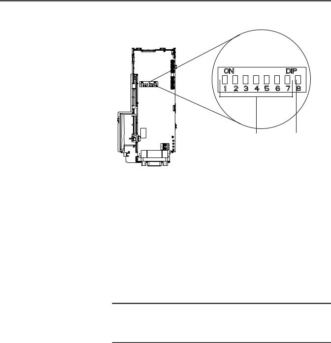
Setting the Endianness and Node Address Using the DIP Switches
Node Address |
Byte Swap |
switches (1...7) |
switch (8) |
Set the Endianness of the adapter with Byte Swap switch 8. The Byte Swap switch can be set to either OFF ‘0’ (Little Endian) or ON ‘1’ (Big Endian) data formats for the data exchanged on the network. The data consists of the following items:
•CTRL: Logic Command Word (four bytes)
•REF: Speed Reference (two bytes)
•STAT: Logic Status Word (four bytes)
•FEEDBACK: Speed Feedback (two bytes)
•zero to eight Datalinks (two bytes each)
•Acyclic messaging
Depending on the setting of the Byte Swap switch 8, the two bytes for each of the above data items are swapped.
IMPORTANT Each node on the PROFIBUS network must have a unique address. Set the node address before power is applied because the adapter detects the node address during initialization (Power On Reset). Unless using the Set Slave Address service in which the address change occurs without requiring a power cycle.
Set the Node Address by setting the Node Address switches 1 through 7 to their binary equivalent, where ‘0’ and ‘1’ indicate switch positions ‘OFF’ and ‘ON’ respectively. Node Address Switch Settings on page 15 lists node addresses and the corresponding Node Address switch settings required to set that respective address.
14 |
Rockwell Automation Publication 520COM-UM004A-EN-E - November 2013 |
Installing the Adapter |
Chapter 2 |
|
|
Connecting the Adapter to the Drive
Node Address Switch Settings
Node |
Node Address Switch |
|
|
|
||||
Address |
|
|
|
|
|
|
|
|
7 |
6 |
5 |
4 |
3 |
2 |
1 |
||
|
||||||||
00 |
0 |
0 |
0 |
0 |
0 |
0 |
0 |
|
|
|
|
|
|
|
|
|
|
01 |
0 |
0 |
0 |
0 |
0 |
0 |
1 |
|
|
|
|
|
|
|
|
|
|
02 |
0 |
0 |
0 |
0 |
0 |
1 |
0 |
|
|
|
|
|
|
|
|
|
|
03 |
0 |
0 |
0 |
0 |
0 |
1 |
1 |
|
|
|
|
|
|
|
|
|
|
04 |
0 |
0 |
0 |
0 |
1 |
0 |
0 |
|
|
|
|
|
|
|
|
|
|
05 |
0 |
0 |
0 |
0 |
1 |
0 |
1 |
|
|
|
|
|
|
|
|
|
|
06 |
0 |
0 |
0 |
0 |
1 |
1 |
0 |
|
|
|
|
|
|
|
|
|
|
07 |
0 |
0 |
0 |
0 |
1 |
1 |
1 |
|
|
|
|
|
|
|
|
|
|
08 |
0 |
0 |
0 |
1 |
0 |
0 |
0 |
|
|
|
|
|
|
|
|
|
|
09 |
0 |
0 |
0 |
1 |
0 |
0 |
1 |
|
|
|
|
|
|
|
|
|
|
10 |
0 |
0 |
0 |
1 |
0 |
1 |
0 |
|
|
|
|
|
|
|
|
|
|
11 |
0 |
0 |
0 |
1 |
0 |
1 |
1 |
|
|
|
|
|
|
|
|
|
|
12 |
0 |
0 |
0 |
1 |
1 |
0 |
0 |
|
|
|
|
|
|
|
|
|
|
13 |
0 |
0 |
0 |
1 |
1 |
0 |
1 |
|
|
|
|
|
|
|
|
|
|
14 |
0 |
0 |
0 |
1 |
1 |
1 |
0 |
|
Description of Node Address Switches
Node |
Node Address Switch |
|
|
|
||||
Address |
|
|
|
|
|
|
|
|
7 |
6 |
5 |
4 |
3 |
2 |
1 |
||
|
||||||||
15 |
0 |
0 |
0 |
1 |
1 |
1 |
1 |
|
|
|
|
|
|
|
|
|
|
16 |
0 |
0 |
1 |
0 |
0 |
0 |
0 |
|
|
|
|
|
|
|
|
|
|
17 |
0 |
0 |
1 |
0 |
0 |
0 |
1 |
|
|
|
|
|
|
|
|
|
|
18 |
0 |
0 |
1 |
0 |
0 |
1 |
0 |
|
|
|
|
|
|
|
|
|
|
19 |
1 |
0 |
1 |
0 |
0 |
1 |
1 |
|
|
|
|
|
|
|
|
|
|
20 |
0 |
0 |
1 |
0 |
1 |
0 |
0 |
|
|
|
|
|
|
|
|
|
|
... |
|
|
|
|
|
|
|
|
|
|
|
|
|
|
|
|
|
120 |
1 |
1 |
1 |
1 |
0 |
0 |
0 |
|
|
|
|
|
|
|
|
|
|
121 |
1 |
1 |
1 |
1 |
0 |
0 |
1 |
|
|
|
|
|
|
|
|
|
|
123 |
1 |
1 |
1 |
1 |
0 |
1 |
0 |
|
|
|
|
|
|
|
|
|
|
124 |
1 |
1 |
1 |
1 |
0 |
1 |
1 |
|
|
|
|
|
|
|
|
|
|
125 |
1 |
1 |
1 |
1 |
1 |
0 |
0 |
|
|
|
|
|
|
|
|
|
|
126 |
1 |
1 |
1 |
1 |
1 |
0 |
1 |
|
|
|
|
|
|
|
|
|
|
127 |
1 |
1 |
1 |
1 |
1 |
1 |
1 |
|
|
|
|
|
|
|
|
|
|
Node Address Value |
Description |
00 or 127 |
If the Node Address switches are set to ‘00’ (the default setting) or 127, the adapter uses Device |
|
parameter 05 [Net Addr Cfg] to set the Node Address. See Setting the Node Address on |
|
page 25. |
01...126 |
Node Address used by the adapter. |
|
|
The switch settings can be verified by viewing the Device parameter 06 [Net Addr Act], a read-only parameter, with any of the following drive configuration tools:
•PowerFlex 520-series drive built-in keypad
•PowerFlex 22-HIM-A3 or 22-HIM-C2S HIM
•Connected Components Workbench software (version 3 or greater)
ATTENTION: Risk of injury or death exists. The PowerFlex drive may contain high voltages that can cause injury or death. Remove power from the drive, and then verify power has been discharged before connecting the adapter to the network.
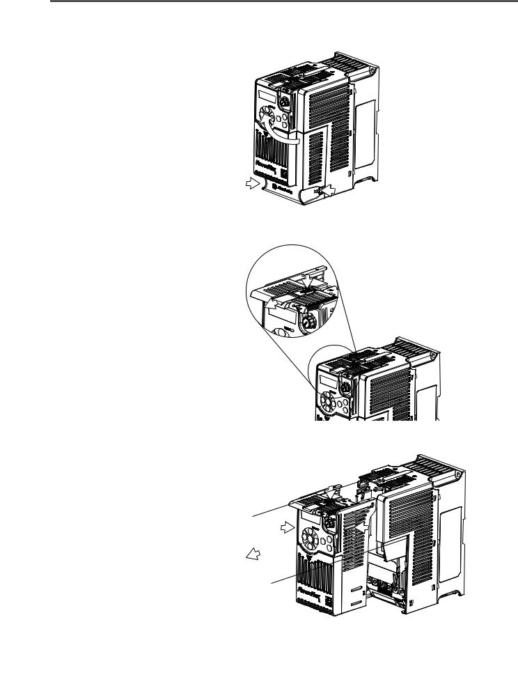
1.Remove power from the drive.
2.Use static control precautions.
3.Separate the drive’s control module from the power module.
Rockwell Automation Publication 520COM-UM004A-EN-E - November 2013 |
15 |
Chapter 2 Installing the Adapter
a.Press and hold down the catch on both sides of the frame cover, then pullout and swing upwards to remove (Frames B...E only).
b.Press down and slide out the top cover of the control module to unlock it from the power module.
c.Hold the sides and top of the control module firmly, then pull out to separate it from the power module.
16 |
Rockwell Automation Publication 520COM-UM004A-EN-E - November 2013 |
Installing the Adapter |
Chapter 2 |
|
|
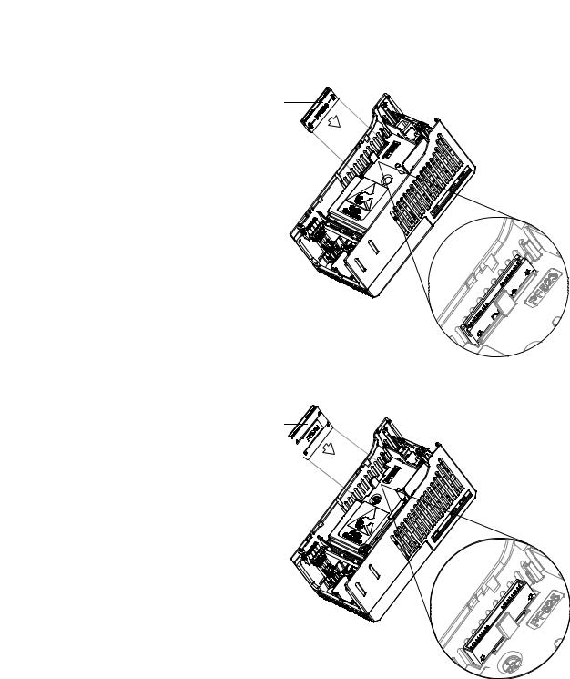
4.Insert the interface connector for the adapter into the header located at the back of the control module.
For PowerFlex 523
Communication adapter interface connector
For PowerFlex 525
Communication 


 adapter interface


 connector


Rockwell Automation Publication 520COM-UM004A-EN-E - November 2013 |
17 |
Chapter 2 Installing the Adapter
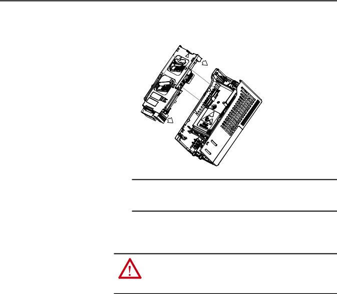
5.Align the Communication card-Drive header on the adapter with the interface connector. Then, press down firmly around the adapter. The adapter snaps into the back of the control module.
Connecting the Adapter to the Network
IMPORTANT The CS1/CS2 terminals on the adapter provide a clean ground for the communication bus cable shields. You should connect the CS1 or CS2 terminal to a clean ground or PE ground on the drive.
6. Attach the control module to the power module.
ATTENTION: Risk of injury or death exists. The PowerFlex drive may contain high voltages that can cause injury or death. Remove power from the drive, and then verify power has been discharged before connecting the adapter to the network.
1.Remove power from the network.
2.Use static control precautions.
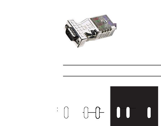
3.Connect a PROFIBUS connector to the cable.
PROFIBUS connectors are available from a variety of sources and in various sizes. As such, there may be mechanical limitations that prohibit the use of some connectors.
Phoenix SUBCON-PLUS-PROFIB/AX/SC (Part #2744380), Siemens 6GK1500-0FC00, or Brad BM5G60PP4Mxxxx are recommended for use with PowerFlex 520-series drives.
18 |
Rockwell Automation Publication 520COM-UM004A-EN-E - November 2013 |
Installing the Adapter |
Chapter 2 |
|
|
PROFIBUS Connector
4.Connect the PROFIBUS cable to the adapter and secure it with the two screws on the connector.
IMPORTANT PROFIBUS communication may not operate correctly if the cable shield does not make full contact with the connector housing.
Network Wiring Diagram
|
|
|
|
|
|
|
|
|
|
|
|
|
|
|
|
|
|
|
|
|
|
|
|
|
|
|
|
|
|
|
|
|
|
|
|
|
|
|
|
|
|
B |
|
A |
|
B |
|
A |
|
|
|
B |
|
A |
|
B |
A |
|
|
|
|
B |
|
A |
|
B |
|
A |
|
||||||||
|
|
|
|
|
|
|
|
|
|
|
|
|
|
|
|
|
||||||||||||||||||||||
|
|
|
|
|
|
|
|
|
|
|
|
|
|
|
|
|
|
|
|
|
|
|
|
|
|
|
|
|
|
|
|
|
|
|
|
|
|
|
|
|
|
|
|
|
|
|
|
|
|
|
|
|
|
|
|
|
|
|
|
|
|
|
|
|
|
|
|
|
|
|
|
|
|
|
|
|
|
|
|
|
|
|
|
|
|
|
|
|
|
|
|
|
|
|
|
|
|
|
|
|
|
|
|
|
|
|
|
|
|
|
|
|
|
|
|
|
|
|
|
|
|
|
|
|
|
|
|
|
|
|
|
|
|
|
|
|
|
|
|
|
|
|
|
|
|
|
|
|
|
|
|
|
|
|
|
|
|
|
|
|
|
|
|
|
|
|
|
|
|
|
|
|
|
|
|
|
|
|
|
|
|
|
|
|
|
|
|
|
|
|
|
|
|
|
|
|
|
|
|
|
|
|
|
|
|
|
|
|
|
|
|
|
|
|
|
|
|
|
|
|
|
|
|
|
|
|
|
|
|
|
|
|
|
|
|
|
|
|
|
|
|
|
|
|
|
|
|
|
|
|
|
|
|
|
|
|
|
|
|
|
|
|
|
|
|
|
|
|
|
|
|
|
|
|
|
|
|
|
|
|
|
|
|
|
|
|
|
|
|
|
|
|
|
|
|
|
|
|
|
|
|
|
|
|
|
|
|
|
|
|
|
|
|
|
|
|
|
|
|
|
|
|
|
|
|
|
|
|
|
|
|
|
|
|
|
|
|
|
|
|
|
|
|
|
|
|
|
|
|
|
|
|
|
|
|
|
|
|
|
|
|
|
|
|
|
|
|
|
|
|
|
|
|
|
|
|
|
|
|
|
|
|
|
|
|
|
|
|
|
Terminal |
Signal |
Function |
|
|
|
Housing |
Shield |
Bus cable shield (outer screen that surrounds A and B conductors) |
|
|
|
1 |
Not connected |
– |
|
|
|
2 |
Not connected |
– |
|
|
|
3 |
B-LINE |
Positive RxD/TxD according to RS485 specification |
|
|
|
4 |
RTS |
Request to send |
|
|
|
5 |
GND BUS |
Network Zero Volt Reference (isolated from drive side) |
|
|
|
6 |
+5V BUS |
+5V output to network (isolated from drive side) |
|
|
|
7 |
Not connected |
– |
|
|
|
8 |
A-LINE |
Negative RxD/TxD according to RS485 specification |
|
|
|
9 |
Not connected |
– |
|
|
|
5.Ground the shield to reduce electrostatic pickup. However, shielding is only effective when the shield is properly connected to ground. See the PROFIBUS Installation Guideline for instructions to correctly ground the shield.
Rockwell Automation Publication 520COM-UM004A-EN-E - November 2013 |
19 |
Chapter 2 Installing the Adapter
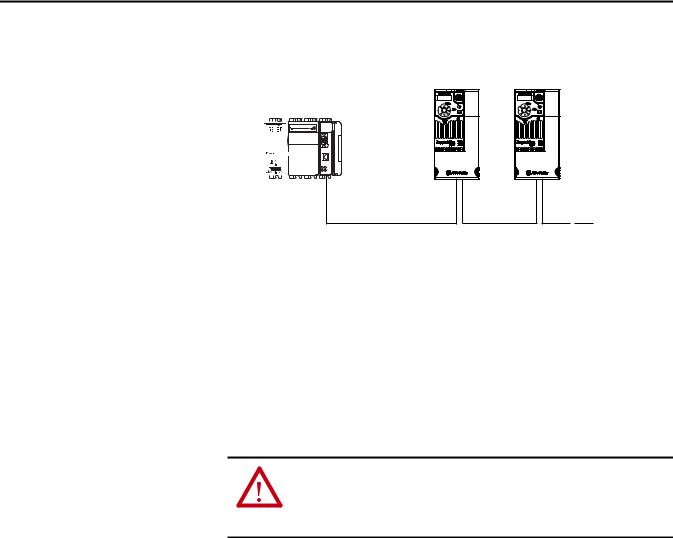
Wiring Example
CompactLogix controller with MVI69-PDPMV1 in slot 1
PROFIBUS |
PowerFlex 525 with 25-COMM-P
Esc |
PowerFlex 525 with 25-COMM-P
Esc |
Network Termination
PROFIBUS network
6.Connect the other end of the PROFIBUS cable to the PROFIBUS network.
The first and last node on a PROFIBUS DP Network segment should be terminated.
Rockwell Automation recommends that the user select one of the aforementioned PROFIBUS connectors with built-in termination.
Applying Power
ATTENTION: Risk of equipment damage, injury, or death exists. Unpredictable operation may occur if you fail to verify that parameter settings are compatible with your application. Verify that settings are compatible with your application before applying power to the drive.
1.Make sure that the adapter will have a unique address on the network and Endianness is set. If a new address is needed, reset its switches (see Commissioning the Adapter on page 13).
2.Apply power to the drive. The adapter receives its power from the connected drive.
3.If the parameter settings for the Endianness and node address are to be used, a configuration tool such as Connected Components Workbench (version 3 or greater) can be used to adjust the respective parameters in the adapter. See Configuring the Adapter on page 23.
Start-Up Status Indication
After power has been applied, the status indicators can be viewed on the front of the drive. When you apply power to the product and network for the first time, the status indicators should be green after an initialization. If the status indicators go red, there is a problem. See Troubleshooting on page 69.
20 |
Rockwell Automation Publication 520COM-UM004A-EN-E - November 2013 |
Installing the Adapter |
Chapter 2 |
|
|
Drive and Adapter Status Indicators
25-COMM-P |
PowerFlex 525 Frame A shown |
|
FWD |
|
ENET LINK |
|
EtherNet/IP |
|
Esc |
Sel |
|
|
|
Item |
Status Indicator |
Status(1) |
Description |
|
PORT |
Green |
Normal operation. The adapter is properly |
|
|
|
connected and is communicating with the |
|
|
|
drive. |
|
|
Flashing green |
The adapter is in the process of establishing a |
|
|
|
connection to the drive. This status indicator |
|
|
|
will turn solid green or red. |
|
MOD |
Green |
Normal operation. The adapter is operational |
|
|
|
and is transferring I/O data. |
|
|
Flashing green |
Normal operation. The adapter is operational |
|
|
|
but is not transferring I/O data. |
|
NET A |
Green |
Normal operation. The adapter is properly |
|
|
|
connected and communicating on the |
|
|
|
network. |
|
|
Flashing green |
The adapter is properly connected but is not |
|
|
|
communicating with any devices on the |
|
|
|
network. |
|
NET B |
Off |
Not used for PROFIBUS network. |
|
|
|
|
(1) If all status indicators are off, the adapter is not receiving power. If any other conditions occur, see Troubleshooting on page 69.
Configuring/Verifying Key Drive Parameters
The PowerFlex 520-series drive can be separately configured for the control and Reference functions in various combinations. For example, you could set the drive to have its control come from a peripheral or terminal block with the Reference coming from the network. Or you could set the drive to have its control come from the network with the Reference coming from another peripheral or terminal block. Or you could set the drive to have both its control and Reference come from the network.
Configuring the Host parameters can be done using the drive’s keypad, a HIM, Logix Designer or Connected Components Workbench. In the following example, the drive will receive the Logic Command and Reference from the network.
1.Set the value of Host parameter P046 [Start Source 1] to 4“Network Opt”.
2.Set the value of Host parameter P047 [Speed Reference1] to 4 “Network Opt”.
Rockwell Automation Publication 520COM-UM004A-EN-E - November 2013 |
21 |

Chapter 2 Installing the Adapter
TIP |
The PowerFlex 520-series drive supports up to three control functions |
|
and three Reference functions. |
For more information on how to set different combinations of the control and Reference functions, see the PowerFlex 520-Series Adjustable Frequency AC Drive User Manual, publication 520-UM001.
22 |
Rockwell Automation Publication 520COM-UM004A-EN-E - November 2013 |

Chapter 3
Configuration Tools
Using the Drive Keypad Interface to Access Parameters
Configuring the Adapter
This chapter provides instructions and information for setting the parameters to configure the adapter.
Topic |
Page |
|
|
Configuration Tools |
23 |
|
|
Using the Drive Keypad Interface to Access Parameters |
23 |
|
|
Using the PowerFlex 4-Class HIM to Access Parameters |
25 |
|
|
Setting the Node Address |
25 |
|
|
Using Master-Slave Hierarchy (Optional) |
26 |
|
|
Setting a Fault Action |
27 |
|
|
Resetting the Adapter |
28 |
|
|
Restoring Adapter Parameters to Factory Defaults |
29 |
|
|
Viewing the Adapter Status Using Parameters |
29 |
|
|
Updating the Adapter Firmware |
29 |
|
|
For a list of parameters, see Adapter Parameters on page 77. For definitions of terms in this chapter, see the Glossary on page 85.
The adapter parameters can be configured using the drive keypad interface (see page 23) or a PowerFlex 4-class HIM (Human Interface Module, see page 25).
Connected Components Workbench (version 3 or greater) can also be used to access the adapter parameters.
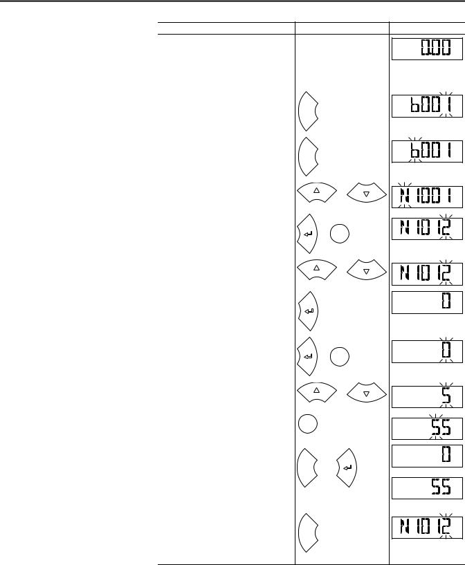
The following is an example of basic integral keypad and display functions. This example provides basic navigation instructions and illustrates how to program a parameter.
IMPORTANT The adapter Device parameters can be accessed on the drive keypad via the “N” (Network) group. Note that the parameters in the “N” group will appear offset from the Device parameter numbers referenced in this manual by 1000 (decimal) on the LCD display.
Rockwell Automation Publication 520COM-UM004A-EN-E - November 2013 |
23 |
Chapter 3 Configuring the Adapter
Step |
Key(s) |
Example Display |
|
1. |
When power is applied, the last user-selected |
|
|
|
Basic Display Group parameter number is briefly |
|
FWD |
|
|
|
|
|
displayed with flashing characters. The display |
|
HERTZ |
|
|
|
|
|
then defaults to that parameter’s current value. |
|
|
|
(Example shows the value of b001 [Output |
|
|
|
Freq] with the drive stopped.) |
|
|
2. |
Press Esc to display the Basic Display Group |
|
|
|
parameter number shown on power-up. The |
|
FWD |
|
parameter number will flash. |
Esc |
|
3. |
Press Esc to enter the parameter group list. The |
|
|
|
parameter group letter will flash. |
|
FWD |
|
|
Esc |
|
4. |
Press the Up Arrow or Down Arrow to scroll |
|
or |
|
through the group list (b, P, t, C, L, d, A, f, N, M, |
|
|
|
|
FWD |
|
|
and Gx). |
|
|
5. |
Press Enter or Sel to enter a group. The right |
|
|
|
digit of the last viewed parameter in that group |
or |
FWD |
|
will flash. |
Sel |
|
6. |
Press the Up Arrow or Down Arrow to scroll |
|
or |
|
through the parameter list. |
|
|
|
|
FWD |
|
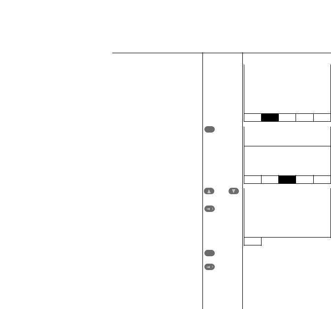
7. Press Enter to view the value of the parameter.
Or |
FWD |
|
Press Esc to return to the parameter list.
8. |
Press Enter or Sel to enter Program Mode and |
|
|
|
|
edit the value. The right digit will flash and the |
|
or Sel |
FWD |
|
word Program on the LCD display will light up. |
|
PROGRAM |
|
9. |
Press the Up Arrow or Down Arrow to change |
|
or |
|
|
the parameter value. |
|
FWD |
|
|
|
|
||
|
|
|
|
PROGRAM |
10. If desired, press Sel to move from digit to digit |
|
|
|
|
|
or bit to bit. The digit or bit that you can change |
Sel |
|
FWD |
|
will flash. |
|
|
PROGRAM |
11. Press Esc to cancel a change and exit Program |
|
|
|
|
|
Mode. |
|
|
FWD |
|
|
|
|
|
|
Or |
Esc |
or |
or |
|
Press Enter to save a change and exit Program |
|
|
|
|
|
|
|
|
|
Mode. |
|
|
FWD |
|
The digit will stop flashing and the word |
|
|
|
|
Program on the LCD display will turn off. |
|
|
|
12. |
Press Esc to return to the parameter list. |
|
|
|
|
Continue to press Esc to back out of the |
|
|
FWD |
|
programming menu. |
Esc |
|
|
|
If pressing Esc does not change the display, then |
|
|
|
|
b001 [Output Freq] is displayed. Press Enter or |
|
|
|
|
Sel to enter the group list again. |
|
|
|
24 |
Rockwell Automation Publication 520COM-UM004A-EN-E - November 2013 |
Configuring the Adapter |
Chapter 3 |
|
|
Using the PowerFlex 4-Class HIM to Access Parameters
The PowerFlex 4-class HIM can be used to access parameters in the adapter (see basic steps shown below). It is recommended that you read through the steps for your HIM before performing the sequence. For additional HIM information, refer to the HIM Quick Reference card, publication 22HIM-QR001.
Step |
Key(s) |
Example Display |
|
1. |
Power up the drive. Then connect the HIM |
|
|
Parameters |
|
||
|
|||
|
to the DSI port of the drive. The Parameters |
|
|
|
tab for the drive will be displayed. |
|
|
|
Groups |
|
|
|
|
||
|
|
|
|
|
|
|
|
|
|
Linear List |
|
|
|
Changed Params |
|
DIAG PARAM DSEL MEM SEL 
2. Press Sel until the DSEL tab is selected. |
|
|
|
|
Sel |
Device Select |
|||
|
||||
|
|
|
|
|
|
|
|
|
|
|
|
|
DSI Devices |
|
|
|
|
|
|
DIAG PARAM DSEL MEM SEL 
3. Select DSI Device in the DSEL tab if it is not |
|
|
|
|
|
and |
DSI Devices |
||
already selected using the Up Arrow or |
|
|||
Down Arrow. |
|
|
|
|
|
|
|
PowerFlex 525 |
|
Press Enter to select DSI Device. |
|
|
|
|
|
|
|
25-COMM-P |
|
|
|
|
||
|
|
|
|
|
4. Press the Up Arrow or Down Arrow to scroll |
|
|
|
|
|
|
|
|
|
|
|
|
|
||
Sel |
DSI Devices |
||||||
to 25-COMM-P. |
|||||||
|
|
|
|
|
|
||
Press Enter to reload the HIM to browse |
|
|
|
|
|
||
|
|
|
|
PowerFlex 525 |
|||
only the communication adapter |
|
|
|
|
|
|
|
|
|
|
|
25-COMM-P |
|||
(25-COMM-P) parameters. |
|
|
|
|
|||
|
|
|
|
|
|
||
|
|
|
|
|
|
|
|
|
|
|
|
|
|
|
|
To display the Host parameters, repeat steps 1 through 3 and select “PowerFlex 525” at step 3.
Setting the Node Address |
The value of Device parameter 05 [Net Addr Cfg] determines the node address if |
|
the adapter’s Node Address switches are set to ‘00’ (Program). When the Node |
|
Address switches are in any other combination of positions, the switches |
|
determine the node address. |
1. Set the value of Device parameter 05 [Net Addr Cfg] to a unique node address.
2. Reset the adapter by power cycling the drive.
Rockwell Automation Publication 520COM-UM004A-EN-E - November 2013 |
25 |

Chapter 3 Configuring the Adapter
Using Master-Slave Hierarchy (Optional)
This procedure is only required if Datalinks are used to write or read data of the drive. A hierarchy determines the type of device with which the adapter exchanges data. In a Master-Slave hierarchy, the adapter exchanges data with a PROFIBUS master, such as a Prosoft MVI69-PDPMV1 Master Network Interface module for CompactLogix.
Configuring a Master-Slave Hierarchy
The controller I/O image can have anywhere from zero to eight (four In and four Out) additional 16-bit parameters called Datalinks. They are configured using
Host parameters C161 [Opt Data In 1] through C164 [Opt Data In 4], and C165 [Opt Data Out 1] through C168 [Opt Data Out 4]. The number of Datalinks actively used is controlled by the connection size in the controller and the in/out parameters. See the respective controller example sections in Configuring the PROFIBUS Master on page 31 for more information on setting the connection size.
When using a ControlLogix or CompactLogix controller and the Generic Profile, or a MicroLogix 1100/1400 controller, configure the Datalink parameters now as described in this section.
Enabling Datalinks To Write Data
IMPORTANT Always use the Datalink parameters in consecutive numerical order, starting with the first parameter. For example, use Host parameters C165, C166, and C167 to configure three Datalinks to write data. Otherwise, the network I/O connection will be larger than necessary, which needlessly increases controller response time and memory usage.
Host parameters C165 [Opt Data Out 1] through C168 [Opt Data Out 4] control which parameters in the drive send values to the network. To configure these parameters, set them to the drive parameter number you want to correlate them to.
The following steps are required to enable Datalinks to write data:
1.Set the values of only the required number of contiguous drive-to-network Datalinks needed to write data to the network and that are to be included in the network I/O connection.
2.Reset the adapter by power cycling the drive.
After the above steps are complete, the adapter is ready to send output data and transfer status data to the master (controller). Next, configure the controller to recognize and transmit I/O to the adapter. See Configuring the PROFIBUS Master on page 31.
26 |
Rockwell Automation Publication 520COM-UM004A-EN-E - November 2013 |

Configuring the Adapter |
Chapter 3 |
|
|
Setting a Fault Action
Enabling Datalinks To Read Data
IMPORTANT Always use the Datalink parameters in consecutive numerical order, starting with the first parameter. For example, use Host parameters C161, C162, and C163 to configure three Datalinks to read data. Otherwise, the network I/O connection will be larger than necessary, which needlessly increases controller response time and memory usage.
Host parameters C161 [Opt Data In 1] through C164 [Opt Data In 4] configure which parameters in the drive receive values from the network. To configure these parameters, set them to the parameter number you wish to correlate them to.
The following steps are required to enable Datalinks to read data:
1.Set the values of only the required number of contiguous network-to-drive Datalinks needed to read data from the network and that are to be included in the network I/O connection.
2.Reset the adapter by power cycling the drive.
After the above steps are complete, the adapter is ready to receive input data from the master (controller). Next, configure the controller to recognize and transmit I/O to the adapter. See Configuring the PROFIBUS Master on page 31.
By default, when communications are disrupted (the network cable is disconnected) and/or the controller is idle (in program mode or faulted), the drive responds by faulting if it is using I/O from the network. You can configure a different response to these events:
•Disrupted I/O communication by using Device parameter
11 [Comm Flt Action].
•An idle controller by using Device parameter 12 [Idle Flt Action].
ATTENTION: Risk of injury or equipment damage exists. Device parameters 11 [Comm Flt Action] and 12 [Idle Flt Action] respectively let you determine the action of the adapter and drive if communications are disrupted or the controller is idle. By default, these parameters fault the drive. You may configure these parameters so that the drive continues to run, however, precautions should be taken to ensure that the settings of these parameters do not create a risk of injury or equipment damage. When commissioning the drive, verify that your system responds correctly to various situations (a disconnected network cable or a controller in idle state).
Rockwell Automation Publication 520COM-UM004A-EN-E - November 2013 |
27 |

Chapter 3 Configuring the Adapter
Changing the Fault Action
Set the values of Device parameters 11 [Comm Flt Action] and 12 [Idle Flt
Action] to the desired responses:
Value |
Action |
Description |
|
|
|
0 |
Fault |
The drive is faulted and stopped. Datalink data is no longer sent to the drive. (Default) |
|
|
|
1 |
Stop |
The drive is stopped as per Host parameter P045 [Stop Mode] setting. Datalink data sent to |
|
|
the drive remains unchanged. |
2 |
Zero Data |
The drive is sent “0” values for all Reference and Datalink data. This does not command a stop. |
|
|
|
3 |
Hold Last |
The drive continues in its present state. |
|
|
|
4 |
Send Flt Cfg |
The drive is sent the Reference and Datalink data that you set in the fault configuration |
|
|
parameters (Device parameters 13 [Flt Cfg Logic], 14 [Flt Cfg Ref], and 15 [Flt Cfg DL 1] |
|
|
through 18 [Flt Cfg DL 4]). |
Changes to these parameters take effect immediately. A reset is not required.
If communication is disrupted and then re-established again, the drive will automatically receive commands over the network again.
Setting the Fault Configuration Parameters
When setting Device parameters 11 [Comm Flt Action] and 12 [Idle Flt Action] to 4 “Send Flt Cfg,” the values in the following parameters are sent to the drive after a communications fault and/or idle fault for drive control occurs. You must set these parameters to values required by your application.
Device Parameter |
Description |
|
13 |
[Flt Cfg Logic] |
A 16-bit integer value sent to the drive for Logic Command. |
|
|
|
14 |
[Flt Cfg Ref] |
A 16-bit integer value sent to the drive for Reference. |
|
|
|
15 |
[Flt Cfg DL 1] through |
A 16-bit integer value sent to the drive for a Datalink. |
18 |
[Flt Cfg DL 4] |
|
Resetting the Adapter
Changes to these parameters take effect immediately. A reset is not required.
Changes to switch settings on some adapter parameters require that you reset the
adapter before the new settings take effect. You can reset the adapter by cycling power to the drive or by using Device parameter 19 [Reset Module].
ATTENTION: Risk of injury or equipment damage exists. If the adapter is transmitting control I/O to the drive, the drive may fault when you reset the adapter. Determine how your drive will respond before resetting the adapter.
Set Device parameter 19 [Reset Module] to 1 “Reset Module”.
Value |
Description |
|
|
0 |
Ready (Default) |
|
|
1 |
Reset Module |
|
|
2 |
Set Defaults |
28 |
Rockwell Automation Publication 520COM-UM004A-EN-E - November 2013 |

Configuring the Adapter |
Chapter 3 |
|
|
Restoring Adapter Parameters to Factory Defaults
When you enter 1 “Reset Module”, the adapter will be immediately reset. An alternate method to reset the adapter is by power cycling the drive.
Set Device parameter 19 [Reset Module] to 2 “Set Defaults”.
Value |
Description |
|
|
0 |
Ready (Default) |
|
|
1 |
Reset Module |
|
|
2 |
Set Defaults |
Viewing the Adapter Status
Using Parameters
When you enter 2 “Set Defaults”, the adapter will set all of its parameters to their factory default values.
IMPORTANT When performing a “Set Defaults” action, the drive may detect a conflict and then not allow this function to occur. If this happens, first resolve the conflict and then repeat a “Set Defaults” action. Common reasons for a conflict include the drive running or a controller in Run mode.
After performing a “Set Defaults” action, you must enter 1 “Reset Module” or power cycle the drive so that the new values take effect. Thereafter, this parameter will be restored to a value of 0 “Ready”.
The following Device parameters provide information about the status of the adapter. You can view these parameters at any time using the PowerFlex 22-HIM-A3 or 22-HIM-C2S HIM or Connected Components Workbench.
PROFIBUS DP Adapter Status Parameters
Name |
Description |
|
02 |
[DLs From Net Act] |
Displays the number of network-to-drive Datalinks that the drive is using based on the I/O |
|
|
connection opened by the controller. |
03 |
[DLs To Net Act] |
Displays the number of drive-to-network Datalinks that the controller is using based on the |
|
|
I/O connection opened by the controller. |
04 |
[Net Addr Src] |
Displays the source from which the adapter’s node address is taken. This will be either the |
|
|
Node Address switches (see Setting the Endianness and Node Address Using the DIP Switches |
|
|
on page 14) or the value of Device parameter 05 [Net Addr Cfg]. |
06 |
[Net Addr Act] |
Displays the actual network node address used by the adapter, which can be one of the |
|
|
following: |
•The address set with the Node Address switches (see Setting the Endianness and Node Address Using the DIP Switches on page 14).
•The Set Slave Address service, sets the value of the new address into the Device parameter 05 [Net Addr Cfg]. It is saved in Non-volatile memory, but takes effect immediately.
•An old address from the switches or parameter. (If either has been changed, but the adapter has not been reset, the new address will not be in effect.)
Updating the Adapter
Firmware
The adapter firmware can be updated over the network or through DSI using a tool such as the 1203-USB serial converter.
When updating firmware over the network or DSI, you can use the Allen-Bradley ControlFLASH software tool.
Rockwell Automation Publication 520COM-UM004A-EN-E - November 2013 |
29 |
Loading...