


Rockwell Automation 440N-Z21U16A, 440N-Z21U16B, 440N-Z21U16H, 440N-Z21U16J, 440N-Z21U26A User Manual
...SensaGuard™ 18 mm Plastic Barrel Unique Coding 440N-Z21U16*, 440N-Z21U26*
Installation Instructions
Original instructions in English
IMPORTANT |
SAVE THESE INSTRUCTIONS FOR FUTURE USE. |
|
|
|
|
ENGLISH: This instruction sheet is available in multiple languages at www.rockwellautomation.com/literature. Select publication language and type "SensaGuard" in the search field.
GERMAN: Dieses Instruktionsblatt kann in mehreren Sprachen unter www.rockwellautomation.com/literature gelesen werden. Bitte Ihre Sprache anwählen und "SensaGuard" im Suchfeld eintippen.
FRENCH: Ces instructions sont disponibles dans différentes langues à l'adresse suivante www.rockwellautomation.com/ literature. Sélectionner la langue puis taper “SensaGuard” dans le champ de recherche.
ITALIAN: La presente scheda d'istruzione è disponibile in varie lingue sul sito www.rockwellautomation.com/literature. Selezionare la lingua desiderata e digitare "SensaGuard" nel campo di ricerca.
SPANISH: Puede encontrar esta hoja de instrucciones en varios idiomas en www.rockwellautomation.com/literature. Seleccione el idioma de publicación y escriba "SensaGuard" en el campo de búsqueda.
PORTUGUESE: Esta folha de instruções está disponível em várias línguas em www.rockwellautomation.com/literature. Seleccione a língua de publicação e entre com "SensaGuard" no espaço de busca.
POLISH: Ta kartka z instrukcjami jest dostepna w wielu jezykach na stronie: www.rockwellautomation.com/literature Wybierz jezyk publikacji i wpisz w polu poszukiwania "SensaGuard".
Installation Instructions
Installation must be in accordance with the following steps and stated specifications and should be carried out by suitable competent personnel. The unit is not to be used as a mechanical stop. Guard stops and guides must be fitted. Adherence to the recommended maintenance instructions forms part of the warranty.
This device is intended to be part of the safety related control system of a machine. Before installation, a risk assessment should be performed to determine whether the specifications of this device are suitable for all foreseeable operational and environmental characteristics of the machine to which it is to be fitted. Refer to Technical Specifications below for certification information and ratings.
|
ATTENTION |
|
The presence of spare actuators compromise the |
|
|
|
integrity of the safety systems. Personal injury or |
|
|
|
|
|
|
|
death, property damage or economic loss can |
|
|
|
result. Appropriate management controls, working |
|
|
|
procedures and alternative protective measures |
|
|
|
should be introduced to control their use and |
|
|
|
availability. |
|
|
|
|
|
|
|
Do not defeat, tamper, remove or bypass this unit. |
|
WARNING |
|
|
|
|
|
Severe injury to personnel could result. The sensor |
|
|
|
|
|
|
|
MUST be connected to a Class 2 SELV 24V DC, |
|
|
|
+10%/-15% power supply. |
|
|
|
|
Operating Characteristics
Sensing Distance |
18 mm Actuator |
30 mm Actuator |
|
|
|
|
|
Assured Make |
15 mm |
25 mm |
|
|
|
|
|
Assured OFF |
25 mm |
35 mm |
|
|
|
|
|
Typical Misalignment |
(±7 mm in both axes) |
|
|
|
|
|
|
Repeat Accuracy |
10% of sensing range |
|
|
|
|
|
|
Max. output current (all outputs) |
200 mA |
|
|
|
|
||
Input Current |
50 mA (no load supply current) |
||
|
|
|
|
Operational Current, Min. |
1 mA DC |
|
|
|
|
|
|
Off-state Current |
<0.5 mA DC |
|
|
|
|
||
Max. no. of switches, connected in |
Unlimited. See Unit Response Time section on |
||
series |
page 5. |
|
|
|
|
|
|
Operating Voltage |
24V DC +10%/-15% |
|
|
Class 2 SELV power supply |
|||
|
|||
|
|
|
|
Frequency of operating cycle |
1 Hz |
|
|
|
|
|
|
Response Time (Off) |
54 ms first switch, |
|
|
18 ms for each additional switch |
|||
|
|||
|
|
|
|
Case Material |
Polycarbonate |
|
|
|
|
|
|
Actuator Material |
Polycarbonate |
|
|
|
|
|
|
Outputs (guard door closed, actuator in place)
Outputs |
Description |
Status |
|
|
|
Safety |
2 x PNP, 0.2 A max. |
ON (+24V DC) |
|
|
|
Auxiliary |
1 x PNP, 0.2 A max. |
OFF (0V DC) |
|
|
|
Environmental
Technical Specifications
|
Type 4 Interlocking Device per ISO 14119 (High Coding) |
|
Safety Classification |
PLe, Cat 4 per ISO 13849-1 |
|
|
SIL CL3 per IEC 62061 and IEC 61508 |
|
|
|
|
Standards |
ISO 14119, IEC 60947-5-3, IEC 61508, IEC 62061, ISO 13849- |
|
1, UL 508, CSA 22.2 No. 14 |
||
|
||
|
|
|
Certifications |
TÜV, CE Marked for all applicable directives, cULus |
|
|
|
|
Functional Safety Data |
PFH : 1.12 - 10-9 |
|
|
D |
Operating Temperature [C (F)] |
-10…+55 ° (14…131 °) |
|
|
|
|
Operating Humidity |
5…95% relative |
|
|
|
|
Washdown Rating |
NEMA 3, 4X, 12, 13, IP69k |
|
|
|
|
Shock & Vibration |
IEC 68-2-27 30 g, 11 ms/IEC 68-2-6 |
|
10…55 Hz |
||
|
||
|
|
|
Radio Frequency |
IEC 61000-4-3 |
|
IEC 61000-4-6 |
||
|
||
|
|
Rockwell Automation 440N-IN013A-EN-P—October 2014

2 |
SensaGuard™ 18 mm Plastic Barrel Unique Coding |
Protection
Short-circuit |
Incorporated |
|
|
Current Limitation |
Incorporated |
|
|
Overload |
Incorporated |
|
|
False Pulse |
Incorporated |
|
|
Transient Noise |
Incorporated |
|
|
Reverse Polarity |
Incorporated |
|
|
Overvoltage |
Incorporated |
|
|
Thermal Shutdown/Restart |
Incorporated |
|
|
Electrical Life |
10 x 106 |
Dimensions [mm (in.)]
16.84 |
|
|
|
|
|
|
|
|
|
[0.663] |
|
|
|
|
|
|
|
|
|
3.17 |
|
|
|
|
|
|
|
4.57 |
Dia. |
[0.125] |
|
|
|
|
|
|
|
[0.18] |
|
|
|
|
|
|
|
|
|
2 places |
|
|
|
|
|
|
22.22 |
|
|
|
|
|
|
|
|
48.92 |
[0.875] |
|
|
|
|
|
|
30.40 |
|
[1.926] |
|
|
|
|
|
|
|
[1.197] |
|
|
|
|
|
|
|
|
|
|
|
|
|
19.81 |
|
|
|
|
|
|
|
|
|
[0.78] |
|
|
|
|
|
|
|
|
|
|
19.81 |
|
|
|
|
|
|
|
|
|
[0.78] |
22.22 |
|
|
|
|
|
|
|
|
|
|
|
|
|
|
|
|
|
|
|
[0.875] |
|
|
30 mm Actuator |
|
|
|
|
|
48.92 |
|
|
|
|
|
|
|
|
|
|
[1.926] |
|
15.42 |
|
|
|
|
|
|
|
|
|
[0.607] |
|
|
|
|
4.57 |
|
|
|
|
3.17 |
|
|
|
|
DIA |
|
|
|
|
|
|
|
|
[0.180] |
|
|
|
||
[0.125] |
|
|
|
|
2 PLACES |
|
67.06 |
|
|
|
|
|
|
|
|
|
2.03 |
[2.640] |
|
|
|
15.87 |
|
|
|
|
[.080] |
|
|
|
36.47 |
|
|
|
|
|
|
|
|
19.81 |
[0.625] |
|
|
|
|
|
|
|
|
[1.436] |
|
|
|
|
|
|
|
|
|
[0.78] |
|
13.72 |
|
|
|
|
|
|
|
|
|
[0.54] |
|
|
|
|
|
|
|
|
|
|
13.72 |
|
|
|
|
M18X1 |
|
|
|
|
[0.54] |
15.87 |
|
|
|
|
|
|
|
|
|
[0.625] |
|
|
|
Sensor |
|
18 mm Actuator |
|
|
36.47 |
|
|
|
|
||
|
|
|
|
[1.436] |
|
|
|
|
|
Mode of Operation
Status indicators:
•“Power/Fault” LED illuminates green: Door/guard closed, safety outputs active.
•“Power/Fault” LED illuminates red: Door/guard open, safety outputs off.
•“Power/Fault” LED flashes red: Unit failure. See Diagnostic section on page 3.
•“Power/Fault” LED flashes green: Safety inputs off.
Mounting Information
Use non-removable screws, bolts, or nuts to mount the switch and actuator. Do not over torque the mounting hardware.
Position the switch and actuator so they are aligned with each other.
Mount the switch and actuator to removable guard, door, or gate. Keep the switch and actuator within the sensing range below.
This switch is not meant to be fully embedded in metal. Use the stainless steel version (440N-Z21S17* or 440N-Z21U17*) for embedding.
Nut Torque Specification
Plastic Barrel Switch: 2.26 N•m (20 in•lb)
Plastic Actuators: 2.26 N•m (20 in•lb)
Minimum Distance Between Sensors
|
|
|
|
|
|
|
|
|
|
|
|
|
|
|
|
|
|
18 mm Actuator |
|
|
|
|
|
|
|
30 mm Actuator |
|
|
|
|
|
|
|||
|
|
|
|
|
|
|
|
|
|
|
|
|
|
|
|
||
|
|
|
|
|
|
|
|
|
|
|
|
|
|
|
|
|
|
|
|
|
|
75 mm |
|
|
|
|
|
|
|
|
|||||
|
|
|
|
|
|
|
|
|
|
|
|
|
|
100 mm |
|||
|
|
|
|
|
|
|
|
|
|
|
|
|
|
|
|
|
|
Sensor |
Sensor |
Sensor |
Sensor |
1 |
2 |
1 |
2 |
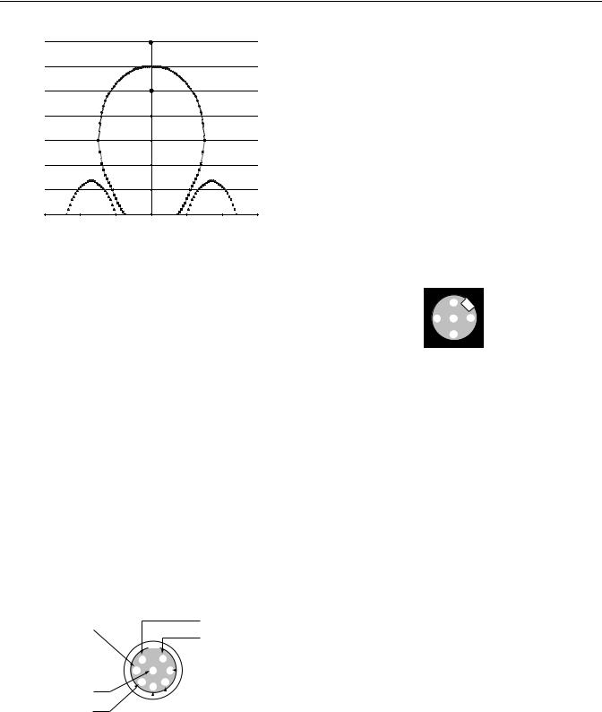
Misalignment Curve
18 mm Unit with 18 mm Target
|
25 |
|
|
|
Assured Sensing |
|
|
|
|
||
|
|
|
|
|
|
Distance |
|
|
|
|
|
|
|
|
|
|
|
OFF |
|
|
|
|
|
|
20 |
|
|
|
|
|
|
|
|
|
|
Distance—mm |
|
OFF |
|
|
|
|
|
|
|
OFF |
|
15 |
|
|
|
Assured Sensing |
|
|
|
|
|||
|
|
|
|
|
|
|
|
||||
|
|
|
|
|
Distance |
|
|
|
|
|
|
|
|
|
|
|
|
|
|
|
|
|
|
Face to Face |
10 |
|
|
|
|
ON |
|
|
|
|
|
5 |
Side Lobe |
|
|
|
|
|
Side Lobe |
|
|||
|
|
|
|
|
|
|
|||||
|
0 |
-20 |
-15 |
-10 |
-5 |
0 |
5 |
10 |
15 |
20 |
25 |
|
-25 |
||||||||||
|
(-0.98)(-0.787) (-0.59) (-0.39) (-0.19) |
(0.19) |
(0.39) |
(0.59) (0.787) |
(0.98) |
||||||
Lateral Misalignment Tolerance—mm (in)
|
IMPORTANT |
|
There must be a minimum spacing of 4 mm |
|
|
(0.157 in.) if actuator and sensor face approaches |
|
|
|
|
|
|
|
|
laterally. This will prevent false triggering due to |
|
|
|
the side lobe areas. |
|
|
|
|
Rockwell Automation 440N-IN013A-EN-P—October 2014
SensaGuard™ 18 mm Plastic Barrel Unique Coding |
3 |
18 mm Unit with 30 mm Target
|
35 |
|
|
OFF |
|
|
|
|
|
|
Assured Sensing |
|
|
|
|
|
|
|
|
|
|
|
|
|
30 |
|
|
Distance |
|
|
|
|
|
|
|
|
|
|
|
Distance—mm |
25 |
|
|
Assured Sensing |
|
|
|
|
OFF |
|
|
OFF |
|
||
20 |
|
Distance |
|
|
|||
|
|
ON |
|
|
|
||
|
|
|
|
|
|
||
15 |
|
|
|
|
|
|
|
to Face |
|
|
|
|
|
|
|
10 |
|
|
|
|
|
|
|
Face |
|
|
|
|
|
|
|
|
Side Lobe |
|
|
|
Side Lobe |
|
|
|
|
|
|
|
|
||
|
5 |
|
|
|
|
|
|
|
0 |
-20 |
-10 |
0 |
10 |
20 |
30 |
|
-30 |
||||||
|
(-1.18) |
(-0.787) |
(-0.39) |
|
(0.39) |
(0.787) |
(1.18) |
Lateral Misalignment Tolerance—mm (in)
|
IMPORTANT |
|
There must be a minimum spacing of 7 mm |
|
|
(0.275 in.) if actuator and sensor face approaches |
|
|
|
|
|
|
|
|
laterally. This will prevent false triggering due to |
|
|
|
the side lobe areas. |
|
|
|
|
Wiring Diagram
8-Pin Unit
Pin Number |
Wire Color |
Signal |
|
|
|
1 |
White |
Aux. Outputs |
|
|
|
2 |
Brown |
+24V |
|
|
|
3 |
Green |
NA |
|
|
|
4 |
Yellow |
OSSD 2, +24V Input |
|
|
|
5 |
Grey |
OSSD 1 |
|
|
|
6 |
Pink |
OSSD 2 |
|
|
|
7 |
Blue |
0V |
|
|
|
8 |
Red |
OSSD 1, +24V Input |
|
|
|
Recommended mating cable, 2 m (6.5 ft)—889D-F8AB-2. Replace the 2 with 5 (5 m) or 10 (10 m) for standard cable lengths.
Brown
Green
White
|
|
|
|
|
|
|
2 |
|
|
1 |
|
|
|
3 |
8 |
7 |
|
Blue |
||
|
||||||
4 |
5 |
6 |
|
|
||
Red |
|
|
|
|
|
Pink |
|
|
|
|
|
||
Yellow |
|
|
|
|
|
|
|
|
|
|
|
||
|
|
|
|
|
Grey |
|
|
|
|
|
|
|
|
|
|
|
|
|
|
|
5-Pin Unit
Pin Number |
Signal |
|
|
1 |
+24V |
|
|
2 |
OSSD 1 |
|
|
3 |
0V |
|
|
4 |
OSSD 2 |
|
|
5 |
Aux. |
|
|
Recommended cordset, 2m (6.5 ft) - 889D-F5AC-2. Replace the 2 with 5 (5 m) or 10 (10 m) for standard cable lengths.
Note: If the user does not require the Auxiliary signal, a 4-pin cordset (889D-F4AC-2) can be used.
Recommended patchcord for use with ArmorBlock® Guard Safety I/O, 2 m (6.5 ft) - 889D-F4ACDM-2. Replace the 2 with 0M3 (0.3 m), 1 (1 m), 5 (5 m), or 10 (10 m) for standard cable lengths.
Note: Do not use a 5-pin patchcord with the ArmorBlock.
|
2 |
|
3 |
5 |
1 |
|
4 |
|
Diagnostic
Unit Indicators (per IEC 60073)
|
|
State |
|
Status |
Troubleshooting |
||
|
|
|
|
|
|
|
|
|
|
Off |
|
Not Powered |
NA |
||
|
|
|
|
|
|
|
|
|
|
Red |
|
Not Safe, OSSD not active |
NA |
||
|
|
|
|
|
|
|
|
|
Device |
Green |
|
Safe, OSSD active |
NA |
||
|
|
|
|
|
|
|
|
|
Output |
Green |
|
Power up test or OSSD inputs |
Check 24V DC or OSSD inputs |
||
|
LED |
|
|||||
|
Flash |
|
not valid |
(yellow and red wire) |
|||
|
|
|
|||||
|
|
|
|
|
|
|
|
|
|
|
|
|
|
|
Recoverable fault —check |
|
|
Red |
|
1 Hz Flash Recoverable Fault |
OSSD outputs are not shorted |
||
|
|
Flash |
|
4 Hz Flash Non-recoverable Fault |
to GND, 24V DC or each other. |
||
|
|
|
|
|
|
|
Cycle power. |
|
|
|
|
|
|
|
|
|
|
|
|
|
|
||
|
IMPORTANT |
|
|
Refer to Technical Specifications (page 1) for |
|||
|
|
|
certification information and ratings. |
||||
|
|
|
|
|
|||
|
|
|
|
|
|
|
|
Rockwell Automation 440N-IN013A-EN-P—October 2014
 Loading...