


Adjustable Frequency AC Drive Drehzahlveränderbarer Frequenzumrichter Variateur de vitesse c.a.
Inverter CA a frequenza variabile Variador de Frecuencia Ajustable de CA Inversor CA de Freqüência Ajustável
FRN 1.xx - 2.xx
Quick Start
Kurzanleitung
Guide de mise en route
Avviamento rapido
Inicio rápido
Início rápido
www.abpowerflex.com

PowerFlex® 40P Adjustable Quick Start
Frequency AC Drive
FRN 1.xx - 2.xx
This Quick Start guide summarizes the basic steps needed to install, start-up and program the PowerFlex 40P Adjustable Frequency AC Drive. The information provided Does Not replace the User Manual and is intended for qualified drive service personnel only.
For detailed PowerFlex 40P information including EMC instructions, application considerations and related precautions, refer to the PowerFlex 40P User Manual, Publication 22D-UM001… at www.rockwellautomation.com/literature.
General Precautions
ATTENTION: The drive contains high voltage capacitors which take
!time to discharge after removal of mains supply. Before working on drive, ensure isolation of mains supply from line inputs [R, S, T (L1, L2, L3)]. Wait three minutes for capacitors to discharge to safe voltage levels. Failure to do so may result in personal injury or death.
Darkened display LEDs is not an indication that capacitors have discharged to safe voltage levels.
ATTENTION: Equipment damage and/or personal injury may result if parameter A092 [Auto Rstrt Tries] or A094 [Start At PowerUp] is used in an inappropriate application. Do not use this function without considering applicable local, national and international codes, standards, regulations or industry guidelines.
ATTENTION: Only qualified personnel familiar with adjustable frequency AC drives and associated machinery should plan or implement the installation, start-up and subsequent maintenance of the system. Failure to comply may result in personal injury and/or equipment damage.
ATTENTION: This drive contains ESD (Electrostatic Discharge) sensitive parts and assemblies. Static control precautions are required when installing, testing, servicing or repairing this assembly. Component damage may result if ESD control procedures are not followed. If you are not familiar with static control procedures, reference A-B publication 8000-4.5.2, “Guarding Against Electrostatic Damage” or any other applicable ESD protection handbook.
ATTENTION: An incorrectly applied or installed drive can result in component damage or a reduction in product life. Wiring or application errors, such as, undersizing the motor, incorrect or inadequate AC supply, or excessive ambient temperatures may result in malfunction of the system.
ATTENTION: Risk of injury or equipment damage exists. Drive does not contain user-serviceable components. Do not disassemble drive chassis.

English-2
Mounting Considerations
• Mount the drive upright on a flat, vertical and level surface.
Frame |
Screw Size |
Screw Torque |
DIN Rail |
|
|
|
|
B |
M4 (#8-32) |
1.56-1.96 N-m (14-17 lb.-in.) |
35 mm |
|
|
|
|
C |
M5 (#10-24) |
2.45-2.94 N-m (22-26 lb.-in.) |
– |
|
|
|
|
• Protect the cooling fan by avoiding dust or metallic particles.
• Do not expose to a corrosive atmosphere.
• Protect from moisture and direct sunlight.
Minimum Mounting Clearances
See page 20 for mounting dimensions.
120 mm
(4.7 in.)
120 mm
(4.7 in.)
25 mm
(1.0 in.)
Closest object that may restrict air flow through the drive heat sink and chassis
120 mm
(4.7 in.)
120 mm
(4.7 in.)
Mounting Option A Mounting Option B
No clearance required between drives.
Ambient Operating Temperatures
Ambient Temperature |
Enclosure Rating |
Minimum Mounting |
|
|
|
|
Clearances |
Minimum |
Maximum |
|
|
|
40°C (104°F) |
IP 20/Open Type |
Use Mounting Option A |
-10°C (14°F) |
|
|
|
IP 30/NEMA 1/UL Type 1(1) |
Use Mounting Option B |
||
|
50°C (122°F) |
IP 20/Open Type |
Use Mounting Option B |
(1) Rating requires installation of the PowerFlex 40P IP 30/NEMA 1/UL Type 1 option kit.
English-3
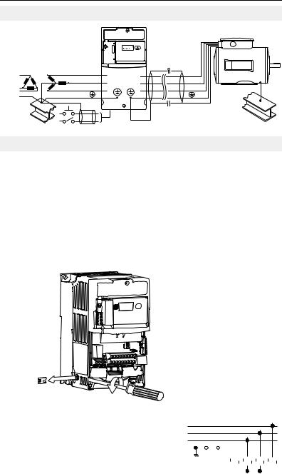
Typical Grounding
|
RUN |
|
REV |
|
FAULT |
R/L1 |
U/T1 |
S/L2 |
V/T2 |
T/L3 |
W/T3 |
SHLD
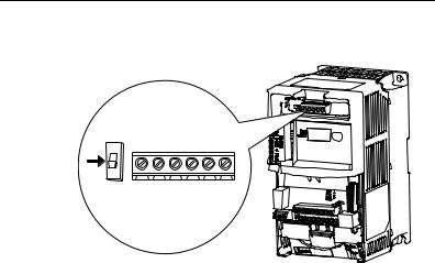
Disconnecting MOVs
To prevent drive damage, the MOVs connected to ground shall be disconnected if the drive is installed on an ungrounded distribution system where the line-to-ground voltages on any phase could exceed 125% of the nominal line-to-line voltage. To disconnect these devices, remove the jumper shown in the figures below.
1.Turn the screw counterclockwise to loosen.
2.Pull the jumper completely out of the drive chassis.
3.Tighten the screw to keep it in place.
Jumper Location
Phase to Ground MOV Removal
Three-Phase R/L1
AC Input S/L2
T/L3
|
|
|
|
|
1 |
|
2 |
|
3 |
|
4 |
|||||||||
Jumper |
|
|
|
|||||||||||||||||
|
|
|
|
|
|
|
|
|
|
|
|
|
|
|
|
|
|
|
|
|
|
|
|
|
|
|
|
|
|
|
|
|
|
|
|
|
|
|
|
|
|
|
|
|
|
|
|
|
|
|
|
|
|
|
|
|
|
|
|
|
|
|
Important: Tighten screw after jumper removal.

English-4
CE Conformity
Refer to the PowerFlex 40P User Manual for details on how to comply with the Low Voltage (LV) and Electromagnetic Compatibility (EMC) Directives.
Specifications, Fuses and Circuit Breakers
Drive Ratings
Catalog |
Output Ratings |
Input Ratings |
|
Branch Circuit Protection |
|
||||
|
|
|
|
|
|
|
|
|
|
Number(1) |
kW (HP) |
Amps |
Voltage |
kVA |
Amps |
Fuses |
140M Motor |
Contactors |
|
|
Range |
Protectors |
|||||||
200 - 240V AC (±10%) – 3-Phase Input, 0 - 230V 3-Phase Output |
|
|
|
||||||
22D-B2P3 |
0.4 |
(0.5) |
2.3 |
180-264 |
1.15 |
2.5 |
6 |
140M-C2E-B40 |
100-C07 |
|
|
|
|
|
|
|
|
|
|
22D-B5P0 |
0.75 (1.0) |
5.0 |
180-264 |
2.45 |
5.7 |
10 |
140M-C2E-C10 |
100-C09 |
|
|
|
|
|
|
|
|
|
|
|
22D-B8P0 |
1.5 |
(2.0) |
8.0 |
180-264 |
4.0 |
9.5 |
15 |
140M-C2E-C16 |
100-C12 |
|
|
|
|
|
|
|
|
|
|
22D-B012 |
2.2 |
(3.0) |
12.0 |
180-264 |
5.5 |
15.5 |
25 |
140M-C2E-C16 |
100-C23 |
|
|
|
|
|
|
|
|
|
|
22D-B017 |
3.7 |
(5.0) |
17.5 |
180-264 |
8.6 |
21.0 |
30 |
140M-F8E-C25 |
100-C23 |
|
|
|
|
|
|
|
|
|
|
22D-B024 |
5.5 |
(7.5) |
24.0 |
180-264 |
11.8 |
26.1 |
40 |
140M-F8E-C32 |
100-C37 |
|
|
|
|
|
|
|
|
|
|
22D-B033 |
7.5 |
(10.0) |
33.0 |
180-264 |
16.3 |
34.6 |
60 |
140M-G8E-C45 |
100-C60 |
|
|
|
|
|
|
|
|
|
|
380 - 480V AC (±10%) – 3-Phase Input, 0 - 460V 3-Phase Output |
|
|
|
||||||
22D-D1P4 |
0.4 |
(0.5) |
1.4 |
342-528 |
1.4 |
1.8 |
3 |
140M-C2E-B25 |
100-C07 |
|
|
|
|
|
|
|
|
|
|
22D-D2P3 |
0.75 (1.0) |
2.3 |
342-528 |
2.3 |
3.2 |
6 |
140M-C2E-B40 |
100-C07 |
|
|
|
|
|
|
|
|
|
|
|
22D-D4P0 |
1.5 |
(2.0) |
4.0 |
342-528 |
4.0 |
5.7 |
10 |
140M-C2E-B63 |
100-C09 |
|
|
|
|
|
|
|
|
|
|
22D-D6P0 |
2.2 |
(3.0) |
6.0 |
342-528 |
5.9 |
7.5 |
15 |
140M-C2E-C10 |
100-C09 |
|
|
|
|
|
|
|
|
|
|
22D-D010 |
4.0 |
(5.0) |
10.5 |
342-528 |
10.3 |
13.0 |
20 |
140M-C2E-C16 |
100-C23 |
|
|
|
|
|
|
|
|
|
|
22D-D012 |
5.5 |
(7.5) |
12.0 |
342-528 |
11.8 |
14.2 |
25 |
140M-D8E-C20 |
100-C23 |
|
|
|
|
|
|
|
|
|
|
22D-D017 |
7.5 |
(10.0) |
17.0 |
342-528 |
16.8 |
18.4 |
30 |
140M-D8E-C20 |
100-C23 |
|
|
|
|
|
|
|
|
|
|
22D-D024 |
11.0 (15.0) |
24.0 |
342-528 |
23.4 |
26.0 |
50 |
140M-F8E-C32 |
100-C43 |
|
|
|
|
|
|
|
|
|
|
|
460 - 600V AC (±10%) – 3-Phase Input, 0 - 575V 3-Phase Output |
|
|
|
||||||
|
|
|
|
|
|
|
|
|
|
22D-E1P7 |
0.75 (1.0) |
1.7 |
414-660 |
2.1 |
2.3 |
6 |
140M-C2E-B25 |
100-C09 |
|
|
|
|
|
|
|
|
|
|
|
22D-E3P0 |
1.5 |
(2.0) |
3.0 |
414-660 |
3.65 |
3.8 |
6 |
140M-C2E-B40 |
100-C09 |
|
|
|
|
|
|
|
|
|
|
22D-E4P2 |
2.2 |
(3.0) |
4.2 |
414-660 |
5.2 |
5.3 |
10 |
140M-C2E-B63 |
100-C09 |
|
|
|
|
|
|
|
|
|
|
22D-E6P6 |
4.0 |
(5.0) |
6.6 |
414-660 |
8.1 |
8.3 |
15 |
140M-C2E-C10 |
100-C09 |
|
|
|
|
|
|
|
|
|
|
22D-E9P9 |
5.5 |
(7.5) |
9.9 |
414-660 |
12.1 |
11.2 |
20 |
140M-C2E-C16 |
100-C16 |
|
|
|
|
|
|
|
|
|
|
22D-E012 |
7.5 |
(10.0) |
12.2 |
414-660 |
14.9 |
13.7 |
25 |
140M-C2E-C16 |
100-C23 |
|
|
|
|
|
|
|
|
|
|
22D-E019 |
11.0 (15.0) |
19.0 |
414-660 |
23.1 |
24.1 |
40 |
140M-D8E-C25 |
100-C30 |
|
|
|
|
|
|
|
|
|
|
|
(1)Ratings apply to all drive types; Panel Mount (N104), Flange Mount (F104), and Plate Drive (H204).
English-5
Category |
Specification |
|
|
|
|
|||
Agency |
|
|
|
|
C U® L US |
Listed to UL508C and CAN/CSA-22.2 |
||
Certification |
|
|
|
|
|
|
||
|
|
|
|
|
|
|
Certified to AS/NZS, 1997 Group 1, Class A |
|
|
|
|
|
|
|
|
|
|
|
|
|
|
|
|
|
Marked for all applicable European Directives |
|
|
|
|
|
|
|
|
||
|
|
|
|
|
|
|
EMC Directive (89/336) |
|
|
|
|
|
|
|
|
EN 61800-3, EN 50081-1, EN 50082-2 |
|
|
|
|
|
|
|
|
Low Voltage Directive (73/23/EEC) |
|
|
|
|
|
|
|
|
EN 50178, EN 60204 |
|
|
|
|
|
|
|
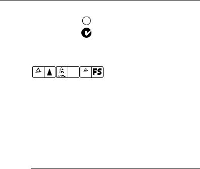
Functional |
Certified to EN 954-1, Category 3. |
|
|
|
|
|
|
|
Bauart geprüft |
Meets Functional Safety (FS) when used with the |
|
|
TUV |
|
|
|
TUV |
Safety |
||
|
.. |
|
|
EN 50178 .. |
|
|
|
|
|
Product Safety |
Production inspected |
Rheinland |
Type approved |
DriveGuard Safe-Off Option (Series B). |
|||
|
Rheinland |
EWC |
|
|
|
|
||
|
|
|
|
|
|
|
||
|
The drive is also designed to meet the appropriate portions of the following specifications: |
|||||||
|
NFPA 70 - US National Electrical Code |
|
|
|||||
|
NEMA ICS 3.1 - Safety standards for Construction and Guide for Selection, Installation and |
|||||||
|
Operation of Adjustable Speed Drive Systems. |
|
||||||
|
IEC 146 - International Electrical Code. |
|
|
|||||
Protection |
Bus Overvoltage Trip |
|
|
|
|
|||
|
200-240V AC Input: |
|
|
405V DC bus (equivalent to 290V AC incoming line) |
||||
|
380-460V AC Input: |
|
|
810V DC bus (equivalent to 575V AC incoming line) |
||||
|
460-600V AC Input: |
|
|
1005V DC bus (equivalent to 711V AC incoming line) |
||||
|
Bus Undervoltage Trip |
|
|
|
|
|||
|
200-240V AC Input: |
|
|
210V DC bus (equivalent to 150V AC incoming line) |
||||
|
380-480V AC Input: |
|
|
390V DC bus (equivalent to 275V AC incoming line) |
||||
|
460-600V AC Input |
|
|
|
|
|||
|
P042 = 3 “High Voltage”: |
|
487V DC bus (equivalent to 344V AC incoming line) |
|||||
|
P042 = 2 “Low Voltage”: |
|
390V DC bus (equivalent to 275V AC incoming line) |
|||||
|
Power Ride-Thru: |
|
|
100 milliseconds |
||||
|
Logic Control Ride-Thru: |
|
|
0.5 seconds minimum, 2 seconds typical |
||||
|
Electronic Motor Overload Protection: |
I2t protection - 150% for 60 seconds, 200% for 3 |
||||||
|
|
|
|
|
|
|
seconds (Provides Class 10 protection) |
|
|
Overcurrent: |
|
|
200% hardware limit, 300% instantaneous fault |
||||
|
Ground Fault Trip: |
|
|
Phase-to-ground on drive output |
||||
|
Short Circuit Trip: |
|
|
Phase-to-phase on drive output |
||||
Environment |
Altitude: |
|
|
1000 m (3300 ft) max. without derating. Above 1000 m |
||||
|
|
|
|
|
|
|
(3300 ft) derate 3% for every 305 m (1000 ft). |
|
|
Maximum Surrounding Air Temperature |
|
|
|||||
|
without derating: |
|
|
|
|
|||
|
IP20, Open Type: |
|
|
–10 to 50° C (14 to 122° F) |
||||
|
IP30, NEMA Type 1, UL Type 1: |
|
–10 to 40° C (14 to 104° F) |
|||||
|
Flange and Plate Mount: |
|
|
Heatsink: |
–10 to 40° C (14 to 104° F) |
|||
|
|
|
|
|
|
|
Drive: |
–10 to 50° C (14 to 122° F) |
|
Cooling Method |
|
|
|
|
|||
|
Convection: |
|
|
0.4 kW (0.5 HP) drives and all Flange and Plate drives |
||||
|
Fan: |
|
|
|
|
|
All other drive ratings |
|
|
Storage Temperature: |
|
|
–40 to 85 degrees C (–40 to 185 degrees F) |
||||
|
Atmosphere: |
|
|
Important: Drive must not be installed in an area |
||||
|
|
|
|
|
|
|
where the ambient atmosphere contains volatile or |
|
|
|
|
|
|
|
|
corrosive gas, vapors or dust. If the drive is not going |
|
|
|
|
|
|
|
|
to be installed for a period of time, it must be stored in |
|
|
|
|
|
|
|
|
an area where it will not be exposed to a corrosive |
|
|
|
|
|
|
|
|
atmosphere. |
|
|
Relative Humidity: |
|
|
0 to 95% non-condensing |
||||
|
Shock (operating): |
|
|
15G peak for 11ms duration (±1.0 ms) |
||||
|
Vibration (operating): |
|
|
1G peak, 5 to 2000 Hz |
||||
Electrical |
Voltage Tolerance: |
|
|
200-240V ±10% |
||||
|
|
|
|
|
|
|
380-480V ±10% |
|
|
|
|
|
|
|
|
460-600V ±10% |
|
|
Frequency Tolerance: |
|
|
48-63 Hz |
|
|||
|
Input Phases: |
|
|
Three-phase input provides full rating. Single-phase |
||||
|
|
|
|
|
|
|
operation provides 35% rated current. |
|
|
Displacement Power Factor: |
|
|
0.98 across entire speed range |
||||
|
Maximum Short Circuit Rating: |
|
100,000 Amps Symmetrical |
|||||
|
Actual Short Circuit Rating: |
|
|
Determined by AIC Rating of installed fuse/circuit |
||||
|
|
|
|
|
|
|
breaker |
|
|
Transistor Type: |
|
|
Isolated Gate Bipolar (IGBT) |
||||

English-6
Category |
Specification |
|
|
Control |
Method: |
|
Sinusoidal PWM, Volts/Hertz, and Sensorless Vector |
|
Carrier Frequency |
2-16 kHz, Drive rating based on 4 kHz. |
|
|
Frequency Accuracy |
|
|
|
Digital Input: |
Within ±0.05% of set output frequency |
|
|
Analog Input: |
Within 0.5% of maximum output frequency, 10-Bit |
|
|
Analog Output: |
resolution |
|
|
±2% of full scale, 10-Bit resolution |
||
|
Speed Regulation |
|
|
|
Open Loop with Slip Compensation: |
±1% of base speed across a 80:1 speed range |
|
|
With Encoder: |
±0.3% of base speed across a 80:1 speed range |
|
|
|
|
±0.05% of base speed across a 20:1 speed range |
|
Output Frequency: |
0-500 Hz (programmable) |
|
|
Efficiency: |
|
97.5% (typical) |
|
Stop Modes: |
|
Multiple programmable stop modes including - Ramp, |
|
|
|
Coast, DC-Brake, and Ramp-to-Stop |
|
Accel/Decel: |
|
Four independently programmable accel and decel |
|
|
|
times. Each time may be programmed from 0 - 600 |
|
|
|
seconds in 0.1 second increments. |
|
Intermittent Overload: |
150% Overload capability for up to 1 minute |
|
|
|
|
200% Overload capability for up to 3 seconds |
|
Electronic Motor Overload Protection |
Class 10 protection with selectable speed sensitive |
|
|
|
|
response and power-down overload retention function |
|
|
|
when enabled. |
Control Inputs |
Digital: |
Bandwidth: |
10 Rad/Secs for open and closed loop |
|
|
Quantity: |
(2) Semi-programmable |
|
|
|
(5) Programmable |
|
|
Current: |
6 mA |
|
|
Type |
|
|
|
Source Mode (SRC): |
18-24V = ON, 0-6V = OFF |
|
|
Sink Mode (SNK): |
0-6V = ON, 18-24V = OFF |
|
Analog: |
Quantity: |
(2) Isolated, –10 to 10V and 4-20mA |
|
|
Specification |
|
|
|
Resolution: |
10-bit |
|
|
0 to 10V DC Analog: |
100k ohm input impedance |
|
|
4-20mA Analog: |
250 ohm input impedance |
|
|
External Pot: |
1-10k ohm, 2 Watt minimum |
Encoder |
Type: |
|
Incremental, dual channel |
|
Supply: |
|
12V, 250 mA. 12V, 10 mA minimum inputs isolated |
|
|
|
with differential transmitter, 250 kHz maximum. |
|
Quadrature: |
|
90°, ±27 degrees at 25 degrees C. |
|
Duty Cycle: |
|
50%, +10% |
|
Requirements: |
Encoders must be line driver type, quadrature (dual |
|
|
|
|
channel) or pulse (single channel), 3.5-26V DC output, |
|
|
|
single-ended or differential and capable of supplying a |
|
|
|
minimum of 10 mA per channel. Allowable input is DC |
|
|
|
up to a maximum frequency of 250 kHz. The encoder |
|
|
|
I/O automatically scales to allow 5V, 12V and 24V DC |
|
|
|
nominal voltages. |
Control Outputs |
Relay: |
Quantity: |
(1) Programmable Form C |
|
|
Specification |
|
|
|
Resistive Rating: |
3.0A at 30V DC, 3.0A at 125V, 3.0A at 240V AC |
|
|
Inductive Rating: |
0.5A at 30V DC, 0.5A at 125V, 0.5A at 240V AC |
|
Opto: |
Quantity: |
(2) Programmable |
|
|
Specification: |
30V DC, 50mA Non-inductive |
|
Analog: |
Quantity: |
(1) Non-Isolated 0-10V or 4-20mA |
|
|
Specification |
|
|
|
Resolution: |
10-bit |
|
|
0 to 10V DC Analog: |
1k ohm minimum |
|
|
4-20mA Analog: |
525 ohm maximum |
|
|
|
|
|
|
English-7 |
|
Power Wiring |
|
|
|
|
|||
Power Wire Rating |
|
|
|
Recommended Copper Wire |
|||
Unshielded 600V, 75°C (167°F) THHN/THWN |
|
15 Mils insulated, dry location |
|||||
Shielded 600V, 75°C or 90°C (167°F or 194°F) RHH/ |
Anixter OLF-7xxxxx, |
||||||
Belden 29501-29507 or |
|||||||
RHW-2 |
|
|
|
|
|
||
|
|
|
|
|
equivalent |
||
|
|
|
|
|
|
||
Shielded Tray rated 600V, 75°C or 90°C (167°F or |
|
Anixter 7V-7xxxx-3G |
|||||
|
Shawflex 2ACD/3ACD or |
||||||
194°F) RHH/RHW-2 |
|
|
|
||||
|
|
|
equivalent |
||||
|
|
|
|
|
|
||
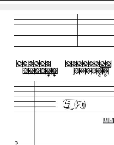
Power Terminal Block |
|
|
|
|
|||
B Frame |
|
|
|
C Frame |
|||
R/L1 S/L2 |
T/L3 |
U/T1 |
V/T2 W/T3 |
R/L1 |
S/L2 T/L3 U/T1 V/T2 W/T3 P2 P1 |
||
DC- |
DC+ |
BR+ |
BR- |
|
|
DCDC+ BR+ BR- |
|
Terminal (1) |
|
Description |
|
|
|
||
R/L1, S/L2 |
|
1-Phase Input (2) |
|
|
|
||
R/L1, S/L2, T/L3 |
3-Phase Input |
|
|
|
|||
U/T1 |
|
To Motor U/T1 |
|
|
Switch any two motor |
||
|
|
|
|
= |
|
||
V/T2 |
|
To Motor V/T2 |
|
leads to change |
|||
W/T3 |
|
To Motor W/T3 |
|
|
forward direction. |
||
|
|
|
|
||||
|
DC Bus Inductor Connection (C Frame drives only.) |
P2, P1 |
The C Frame drive is shipped with a jumper between |
Terminals P2 and P1. Remove this jumper only when a DC |
|
|
Bus Inductor will be connected. Drive will not power up |
|
without a jumper or inductor connected. |
DC+, DC- |
DC Bus Connection |
|
|
BR+, BR- |
Dynamic Brake Resistor Connection |
|
|
|
Safety Ground - PE |
(1)Important: Terminal screws may become loose during shipment. Ensure that all terminal screws are tightened to the recommended torque before applying power to the drive.
(2)Single-phase operation requires a 65% derate of drive rated current.
Power Terminal Block Specifications
Frame |
Maximum Wire Size (1) |
Minimum Wire Size (1) |
Torque |
B |
5.3 mm2 (10 AWG) |
1.3 mm2 (16 AWG) |
1.7-2.2 N-m (16-19 lb.-in.) |
C |
8.4 mm2 (8 AWG) |
1.3 mm2 (16 AWG) |
2.9-3.7 N-m (26-33 lb.-in.) |
(1)Maximum/minimum sizes that the terminal block will accept - these are not recommendations.

English-8
Input Power Conditions
Input Power Condition |
Corrective Action |
||
|
|
|
|
Low Line Impedance (less than 1% line reactance) |
• |
Install Line Reactor(2) |
|
|
• |
or Isolation Transformer |
|
Greater than 120 kVA supply transformer |
|||
• or Bus Inductor – 5.5 & 11 kW |
|||
|
|||
|
|
(7.5 & 15 HP) drives only |
|
|
|
|
|
Line has power factor correction capacitors |
• |
Install Line Reactor |
|
|
• |
or Isolation Transformer |
|
Line has frequent power interruptions |
|||
|
|
||
|
|
|
|
Line has intermittent noise spikes in excess of |
|
|
|
6000V (lightning) |
|
|
|
|
|
|
|
Phase to ground voltage exceeds 125% of normal |
• |
Remove MOV jumper to ground. |
|
line to line voltage |
• |
or Install Isolation Transformer |
|
|
|
with grounded secondary if |
|
Ungrounded distribution system |
|
||
|
necessary. |
||
|
|
||
|
|
|
|
240V open delta configuration (stinger leg)(1) |
• |
Install Line Reactor |
|
(1)For drives applied on an open delta with a middle phase grounded neutral system, the phase opposite the phase that is tapped in the middle to the neutral or earth is referred to as the “stinger leg,” “high leg,” “red leg,” etc. This leg should be identified throughout the system with red or orange tape on the wire at each connection point. The stinger leg should be connected to the center Phase B on the reactor. Refer to the PowerFlex 40P User Manual for specific line reactor part numbers.
(2)Refer to Appendix B of the PowerFlex 40P User Manual for accessory ordering information.
Common Bus/Precharge Notes
If drives with internal precharge are used with a disconnect switch to the common bus, then an auxiliary contact on the disconnect must be connected to a digital input of the drive. The corresponding input (parameter A051-A054) must be set to option 29, “Precharge Enable.” This provides the proper precharge interlock, guarding against possible damage to the drive when connected to a common DC bus.
|
|
|
|
English-9 |
|
|
|
|
|
|
|
|
|
|
|
I/O Wiring Recommendations |
|
||
|
Signal and Control Wire Types |
|
|
|
|
|
|
|
|
|
Signal Type/ |
Belden Wire Type(s)(1) |
|
Min. Insulation |
|
Where Used |
(or equivalent) |
Description |
Rating |
|
Analog I/O & PTC |
8760/9460 |
0.750 mm2(18AWG), twisted |
300V, |
|
|
|
pair, 100% shield with drain (3) |
75-90° C |
|
|
|
|
(167-194° F) |
|
Remote Pot |
8770 |
0.750 mm2 (18AWG), 3 |
|
|
|
|
cond., shielded |
|
|
Encoder/Pulse I/O |
89730(2) |
0.196 mm2 (24AWG), |
|
|
|
|
individually shielded pairs |
|
(1)Stranded or solid wire.
(2)9728 or 9730 are equivalent and may be used but may not fit in the drive wire channel.
(3)If the wires are short and contained within a cabinet which has no sensitive circuits, the use of shielded wire may not be necessary, but is always recommended.
Recommended Control Wire for Digital I/O
|
|
|
|
|
|
Minimum |
Type |
Wire Type(s) |
|
Description |
|
Insulation Rating |
|
Unshielded |
Per US NEC or applicable |
– |
|
300V, |
||
|
national or local code |
|
|
|
60 degrees C |
|
Shielded |
Multi-conductor shielded |
|
0.750 mm2 (18AWG), 3 |
(140 degrees F) |
||
|
cable such as Belden |
|
conductor, shielded. |
|
||
|
8770(or equiv.) |
|
|
|
|
|
I/O Terminal Block Specifications |
|
|
|
|
||
|
|
|
|
|
||
Frame |
Maximum Wire Size (1) |
|
Minimum Wire Size (1) |
Torque |
||
B & C |
1.3 mm2 (16 AWG) |
|
0.2 mm2 (24 AWG) |
0.5-0.8 N-m (4.4-7 lb.-in.) |
||
(1)Maximum/minimum sizes that the terminal block will accept - these are not recommendations.
Refer to the PowerFlex 40P User Manual for recommendations on maximum power and control cable length.
English-10
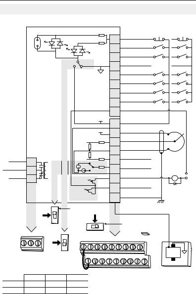
Control Terminal Block
Control Wiring Block Diagram
Enable Jumper (6) |
Typical |
Typical |
Stop (1)(6) |
SRC Wiring |
SNK Wiring |
|
|
|
01 |
|
|
|
Start/Run FWD (2) |
|
|
|
02 |
|
|
|
Direction/Run REV (3) |
|
|
|
03 |
SNK |
SRC |
|
Digital Common |
|
|
|
04 |
|
|
|
Digital Input 1 |
|
|
|
05 |
|
|
|
Digital Input 2 |
|
|
|
06 |
|
|
|
Digital Input 3 |
|
|
|
07 |
|
|
|
Digital Input 4 |
|
|
|
08 |
|
|
|
Opto Common |
|
|
|
09 |
|
|
+24V |
+24V DC |
|
|
|
11 |
|
|
|
|
|
+10V |
12 |
+10V DC |
|
|
|
|||
|
|
|
|
|
|
|
0-10V (or ±10V) Input (4) |
|
|||||
|
|
|
|
|
|
|
13 |
|
|||||
|
|
|
|
|
|
|
|
|
|
|
|
||
|
|
|
|
|
|
|
14 |
Analog Common |
|
||||
|
|
|
|
|
|
|
|
|
|
|
Pot must be |
||
|
|
|
|
|
|
|
|
|
4-20mA Input |
|
|||
Relay N.O. |
|
|
|
|
|
|
15 |
|
1-10k ohm |
||||
R1 |
|
|
0-10V |
|
|
|
|
|
2 Watt Min. |
||||
Relay Common |
|
|
|
|
|
Analog Output |
|||||||
R2 |
|
|
0/4-20mA |
16 |
(5) |
||||||||
|
|
|
|
|
|
||||||||
|
|
|
|
|
|
|
|||||||
Relay N.C. |
|
|
|
|
|
|
|
|
Opto Output 1 |
|
Common |
||
R3 |
|
|
|
|
|
17 |
|
24V |
|||||
|
|
|
|
|
|
|
|
|
|
||||
|
|
|
30V DC |
|
|
|
18 |
Opto Output 2 |
|
|
|||
|
|
|
|
|
|
|
|
|
|
|
|||
|
|
|
50mA |
|
|
|
|
|
RS485 Shield |
|
|
||
|
|
|
Non-inductive |
|
|
19 |
|
|
|||||
|
|
|
|
|
|
|
|
|
|
||||
|
|
0-10V |
Analog Output Select |
|
|
|
|
|
|
|
|||
|
0-20mA |
+/ 10V |
|
(4) |
|
|
|
|
|
|
|||
|
10V |
|
|
|
|
|
|
|
|||||
|
|
|
- |
|
|
|
|
|
Voltage Range Select |
|
|||
R1 R2 R3 |
|
|
|
|
|
|
|
|
ENBL |
Enable (6) |
|
||
SNK |
01 |
02 |
03 |
04 |
05 |
|
|
Jumper |
|
||||
|
|
06 |
07 |
08 |
09 |
|
|
||||||
|
|
|
|
|
|||||||||
|
|
SRC |
|
|
|
|
|
|
|
|
|
|
RS485 |
|
|
|
|
|
|
|
|
|
|
|
|
|
|
|
|
|
|
11 |
12 |
13 |
14 |
15 |
16 |
17 |
18 |
19 |
(DSI) |
|
|
|
|
|
|||||||||
|
|
|
(1) |
|
|
|
|
|
|
|
|
|
1 |
|
|
|
|
|
|
|
|
|
|
|
|
|
|
|
30V DC |
125V AC |
240V AC |
|
|
|
|
|
|
|
|
|
|
Resistive |
3.0A |
3.0A |
3.0A |
|
|
|
|
|
|
|
|
|
|
Inductive |
0.5A |
0.5A |
0.5A |
|
|
|
|
|
|
|
|
|
|
See Control Wiring Block Diagram Notes on next page.

English-11
Control Wiring Block Diagram Notes
(1)Important: I/O Terminal 01 is always a coast to stop input except when P036 [Start Source] is set to “3-Wire”, “2-W Lvl Sens” or “Momt FWD/REV” control. In three wire control, I/O Terminal 01 is controlled by P037 [Stop Mode]. All other stop sources are controlled by P037 [Stop Mode].
P036 [Start Source] |
Stop |
I/O Terminal 01 Stop |
|
|
|
3-Wire |
Per P037 |
Per P037(6) |
2-Wire |
Per P037 |
Coast |
|
|
|
2-W Lvl Sens |
Per P037 |
Per P037(6) |
2-W Hi Speed |
Per P037 |
Coast |
|
|
|
RS485 Port |
Per P037 |
Coast |
|
|
|
Momt FWD/REV |
Per P037 |
Per P037(6) |
Important: The drive is shipped with a jumper installed between I/O Terminals 01 and
11. Remove this jumper when using I/O Terminal 01 as a stop or enable input.
(2)Two wire control shown. For three wire control use a momentary input  on I/O
Terminal 02 to command a start. Use a maintained input 
 for I/O Terminal 03 to change direction.
(3)The function of I/O Terminal 03 is fully programmable. Program with E202 [Digital Term 3].
(4)Match the Voltage Range Select DIP switch setting with the control scheme for proper Uni-Polar or Bipolar operation.
(5)When using an opto output with an inductive load such as a relay, install a recovery diode parallel to the relay as shown, to prevent damage to the output.
(6)When the ENBL enable jumper is removed, I/O Terminal 01 will always act as a hardware enable, causing a coast to stop without software interpretation.

English-12
Control I/O Terminal Designations
No. |
Signal |
Default |
Description |
Param. |
|
|
|
|
|
|
|
R1 |
Relay N.O. |
Fault |
Normally open contact for output relay. |
A055 |
|
|
|
|
|
|
|
R2 |
Relay Common |
– |
Common for output relay. |
|
|
|
|
|
|
|
|
R3 |
Relay N.C. |
Fault |
Normally closed contact for output relay. |
A055 |
|
|
|
|
|
|
|
|
|
|
|
||
Analog Output Select |
0-10V |
Sets analog output to either voltage or current. Setting must match |
|||
DIP Switch |
|
A065 [Analog Out Sel]. |
|
||
|
|
|
|||
Sink/Source |
Source (SRC) |
Inputs can be wired as Sink (SNK) or Source (SRC) via DIP Switch |
|||
DIP Switch |
|
setting. |
|
||
|
|
|
|
|
|
|
|
|
|
|
|
01 |
Stop (1) |
Coast |
The factory installed jumper or a normally closed |
P036 (1) |
|
|
|
|
input must be present for the drive to start. |
|
|
|
|
|
|
|
|
02 |
Start/Run FWD |
Not Active |
I/O Terminal 03 is fully programmable. Program with |
P036, P037 |
|
|
|
|
E202 [Digital Term 3]. To disable reverse operation, |
|
|
03 |
Digital Term 3 |
Not Active |
P036, P037, |
||
see A095 [Reverse Disable]. |
|||||
|
|
|
A095, E202 |
||
|
|
|
|
||
|
|
|
|
|
|
04 |
Digital Common |
– |
For digital inputs. Electronically isolated with digital |
|
|
|
|
|
inputs from analog I/O and opto outputs. |
|
|
|
|
|
|
|
|
05 |
Digital Input 1 |
Preset Freq |
Program with A051 [Digital In1 Sel]. |
A051 |
|
|
|
|
|
|
|
06 |
Digital Input 2 |
Preset Freq |
Program with A052 [Digital In2 Sel]. |
A052 |
|
|
|
|
|
|
|
07 |
Digital Input 3 |
Local |
Program with A053 [Digital In3 Sel]. |
A053 |
|
|
|
|
|
|
|
08 |
Digital Input 4 |
Jog Forward |
Program with A054 [Digital In4 Sel]. |
A054 |
|
|
|
|
|
|
|
09 |
Opto Common |
– |
For opto-coupled outputs. Electronically isolated with |
|
|
|
|
|
opto outputs from analog I/O and digital inputs. |
|
|
|
|
|
|
|
|
11 |
+24V DC |
– |
Referenced to Digital Common. |
|
|
|
|
|
Drive supplied power for digital inputs. |
|
|
|
|
|
Maximum output current is 100mA. |
|
|
|
|
|
|
|
|
12 |
+10V DC |
– |
Referenced to Analog Common. |
P038 |
|
|
|
|
Drive supplied power for 0-10V external |
|
|
|
|
|
potentiometer. |
|
|
|
|
|
Maximum output current is 15mA. |
|
|
|
|
|
|
|
|
13 |
±10V In (2) |
Not Active |
For external 0-10V (unipolar) or ±10V (bipolar) input |
P038, |
|
|
|
|
supply (input impedance = 100k ohm) or |
A051-A054, |
|
|
|
|
potentiometer wiper. |
A123, A132 |
|
|
|
|
|
|
|
14 |
Analog Common |
– |
For 0-10V In or 4-20mA In. Electronically isolated |
|
|
|
|
|
with analog inputs and outputs from digital I/O and |
|
|
|
|
|
opto outputs. |
|
|
|
|
|
|
|
|
15 |
4-20mA In (2) |
Not Active |
For external 4-20mA input supply |
P038, |
|
|
|
|
(input impedance = 250 ohm). |
A051-A054, |
|
|
|
|
|
A132 |
|
|
|
|
|
|
|
16 |
Analog Output |
OutFreq 0-10 |
The default analog output is 0-10V. To covert to a |
A065, A066 |
|
|
|
|
current value, change the Analog Output Select DIP |
|
|
|
|
|
Switch to 0-20mA. Program with A065 [Analog Out |
|
|
|
|
|
Sel]. Max analog value can be scaled with A066 |
|
|
|
|
|
[Analog Out High]. |
|
|
|
|
|
Maximum Load: 4-20mA = 525 ohm (10.5V) |
|
|
|
|
|
0-10V = 1k ohm (10mA) |
|
|
|
|
|
|
|
|
17 |
Opto Output 1 |
MotorRunning |
Program with A058 [Opto Out1 Sel] |
A058, A059, |
|
|
|
|
|
A064 |
|
|
|
|
|
|
|
18 |
Opto Output 2 |
At Frequency |
Program with A061 [Opto Out2 Sel] |
A061, A062, |
|
|
|
|
|
A064 |
|
|
|
|
|
|
|
19 |
RS485 (DSI) Shield |
– |
Terminal should be connected to safety ground - PE |
|
|
|
|
|
when using the RS485 (DSI) communications port. |
|
|
|
|
|
|
|
|
(1)See Footnotes (1) and (6) on page 11.
(2)0-10V In and 4-20mA In are distinct input channels and may be connected simultaneously. Inputs may be used independently for speed control or jointly when operating in PID mode.
English-13
Encoder Interface
The PowerFlex 40P Encoder Interface can source 5 or12 volt power and accept 5, 12 or 24 volt single ended or differential inputs.
12V |
+V Cm B- B A- A |
5V
Terminal Description
No. |
Signal |
Description |
|
|
|
|
|
+V |
5V-12V Power (1) |
Internal power source 250 mA (isolated). |
|
Cm |
Power Return |
||
|
|||
|
|
|
|
B- |
Encoder B (NOT) |
Quadrature B input. |
|
|
|
||
B |
Encoder B |
||
|
|||
|
|
|
|
A- |
Encoder A (NOT) |
Single channel, pulse train, or quadrature A input. |
|
|
|
||
A |
Encoder A |
||
|
|||
|
|
|
|
|
|
|
|
|
Output |
DIP switch selects 12 or 5 volt power supplied at terminals “+V” |
|
|
|
and “Cm” for the encoder. |
|
|
|
|
(1)When using 12V Encoder power, 24V I/O power, maximum output current at I/O Terminal 11 is 50 mA.
Important: A quadrature encoder provides rotor speed and direction. Therefore, the encoder must be wired such that the forward direction matches the motor forward direction. If the drive is reading encoder speed but the position regulator or other encoder function is not working properly, remove power to the drive and swap the A and B encoder channels or swap any two motor leads. Drives using FRN 2.xx and greater will fault when an encoder is incorrectly wired and E216 [Motor Fdbk Type] is set to option 5 “Quad Check”.

English-14
Prepare For Drive Start-Up
 ATTENTION: Power must be applied to the drive to perform the ! following start-up procedures. Some of the voltages present are at
 incoming line potential. To avoid electric shock hazard or damage to equipment, only qualified service personnel should perform the following procedure. Thoroughly read and understand the procedure before beginning. If an event does not occur while performing this procedure, Do Not Proceed. Remove All Power including user supplied control voltages. User supplied voltages may exist even when main AC power is not applied to the drive. Correct the malfunction before continuing.
Before Applying Power to the Drive
1. Confirm that all inputs are connected to the correct terminals and are secure.
2. Verify that AC line power at the disconnect device is within the rated value of the drive.
3. Verify that any digital control power is 24 volts.
4. Verify that the Sink (SNK)/Source (SRC) Setup DIP Switch is set to match your control wiring scheme. See page 10 for location.
Important: The default control scheme is Source (SRC). The Stop terminal is jumpered to allow starting from comms. If the control scheme is changed to Sink (SNK), the jumper must be removed from I/O Terminals 01 and 11 and installed between I/O Terminals 01 and 04.
5. Verify that the Stop input is present or the drive will not start.
Important: If I/O Terminal 01 is used as a stop input, the jumper between I/O Terminals 01 and 11 must be removed.
Applying Power to the Drive
6. Apply AC power and control voltages to the drive.
Start, Stop, Direction and Speed Control
Factory default parameter values allow the drive to be controlled from comms. No programming is required to start, stop, change direction and control speed directly from comms.
Important: To disable reverse operation, see A095 [Reverse Disable].
If a fault appears on power up, refer to page 19 for an explanation of the fault code. For complete troubleshooting information, refer to the PowerFlex 40P User Manual.
English-15
Display/Fault Reset
|
|
|
|
Menu |
|
Description |
|
||
|
|
|
|
|
|
|
|
|
|
|
|
|
|
|
|
|
|
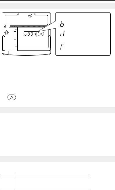
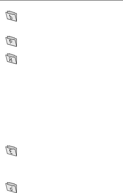
Basic Display Group (View Only) |
|
|
|
|
|
|
|
|
|
||
|
|
|
|
|
|
|
|
Commonly viewed drive operating |
|
|
|
|
|
|
|
|
|
conditions. |
|
|
|
|
|
|
|
|
|
||
|
|
|
|
|
|
|
|
|
|
|
REV |
|
|
|
|
|
|
Advanced Display Group (View Only) |
|
|
|
|
|
|
|
|
|||
|
|
|
|
|
|
|
Consists of advanced drive operating |
||
|
RUN |
|
|
|
|
|
|
|
|
|
FAULT |
|
|
|
|
|
|
conditions. |
|
|
|
|
|
|
|
|
|||
|
|
|
|
|
|
|
|
||
|
|
|
|
|
|
|
|
||
|
|
|
|
|
|
|
|
|
|
|
|
|
|
|
|
|
|
Fault Designator |
|
|
|
|
|
|
|
|
|
||
|
|
|
|
|
|
|
|
Consists of list of codes for specific fault |
|
|
|
|
|
|
|
|
|
conditions. Displayed only when fault is |
|
|
|
|
|
|
|
|
|
present. |
|
|
|
|
|
|
|
|
|
|
|
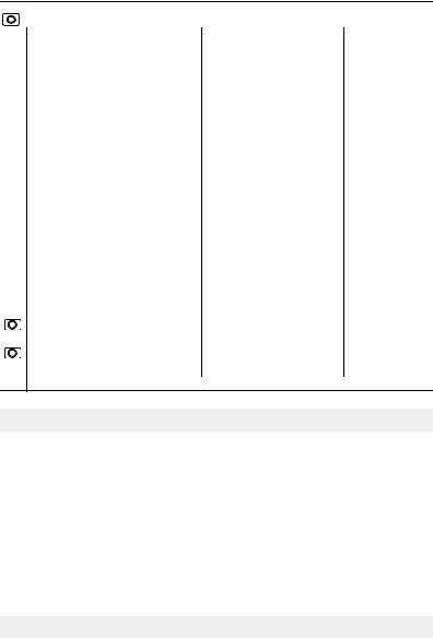
No. |
LED |
LED State |
Description |
|
|
||||
|
|
|
|
|
|
|
|
|
|
|
Run Status |
Steady Red |
Indicates drive is running. |
||||||
|
|
Flashing Red |
Drive has been commanded to change direction. |
||||||
|
|
|
|
|
|
|
|
|
|
|
Direction Status |
Steady Red |
Indicates drive is running in reverse direction. |
||||||
|
|
|
|
|
|
|
|
|
|
|
|
Flashing Red |
Drive has been commanded to change direction and motor is |
||||||
|
|
|
decelerating to zero. |
|
|
||||
|
|
|
|
|
|
|
|
|
|
|
Fault Status |
Flashing Red |
Indicates drive is faulted. |
||||||
|
|
|
|
|
|
|
|
|
|
|
|
|
|
|
|
|
|
|
|
No. |
Key |
Name |
Description |
|
|
||||
|
|
|
|
|
|
|
|
|
|
|
|
Up Arrow |
Scroll: Press and release to scroll through user-selectable |
||||||
|
|
|
Display Group and parameters. |
||||||
|
|
|
Reset: Press and hold for three seconds to clear active fault. |
||||||
|
|
|
|
|
|
|
|
|
|
Drive Programming Tools
For additional drive programming and control, a DSI remote HIM or PC programming tools (DriveExplorer™ or DriveTools™ SP) should be used.
Description |
Catalog Number |
Serial Converter Module |
22-SCM-232 |
|
|
DriveExplorer Software(1) |
9306-4EXP02ENE |
DriveTools SP Software(1) |
9303-4DTS01ENE |
Remote Panel Mount, LCD Display |
22-HIM-C2S |
|
|
Remote Handheld, LCD Display |
22-HIM-A3 |
|
|
(1) Requires a Serial Converter Module. |
|
Set Parameter Display Option
E201 [LED Display Opt]
Selects which parameters can be viewed by the drive’s LED interface.
E201 Option Parameter Set
0All Basic Display (Group b) and Advanced Display (Group d) parameters
1All Basic Display Group (b001-b029) parameters
2Basic Display Group parameters b001-b007 and b010
3Basic Display Group parameter b001-b004
Values |
Default: |
2 |
|
Min/Max: |
0/3 |
|
|
|
|
Display: |
1 |
|
|
|
English-16
Basic Display Group |
Output Voltage |
b004 |
Contrl In Status |
b013 |
Analog In 4-20mA |
b021 |
|
|
|
DC Bus Voltage |
b005 |
Dig In Status |
b014 |
Output Power |
b022 |
|
|
Drive Status |
b006 |
Comm Status |
b015 |
Output Powr Fctr |
b023 |
|
|
Fault 1 Code |
b007 |
Control SW Ver |
b016 |
Drive Temp |
b024 |
|
|
Fault 2 Code |
b008 |
Drive Type |
b017 |
Counter Status |
b025 |
Output Freq |
b001 |
Fault 3 Code |
b009 |
Elapsed Run Time |
b018 |
Timer Status |
b026 |
Commanded Freq |
b002 |
Process Display |
b010 |
Testpoint Data |
b019 |
Stp Logic Status |
b028 |
Output Current |
b003 |
Control Source |
b012 |
Analog In 0-10V |
b020 |
Torque Current |
b029 |
|
|
|
|
|
|
|
|
Basic Program Group |
Motor NP Volts |
P031 |
Minimum Freq |
P034 |
Accel Time 1 |
P039 |
|
|
|
Motor NP Hertz |
P032 |
Maximum Freq |
P035 |
Decel Time 1 |
P040 |
|
|
Motor OL Current |
P033 |
Start Source |
P036 |
Reset To Defalts |
P041 |
|
|
|
|
Stop Mode |
P037 |
Voltage Class |
P042 |
|
|
|
|
Speed Reference |
P038 |
Motor OL Ret |
P043 |
|
|
|
|
|
|
|
|
Advanced Program Group |
Jog Frequency |
A078 |
Anlg Out Setpt |
A109 |
Stp Logic 0 |
A140 |
|
|
|
Jog Accel/Decel |
A079 |
Anlg In 0-10V Lo |
A110 |
Stp Logic 1 |
A141 |
|
|
DC Brake Time |
A080 |
Anlg In 0-10V Hi |
A111 |
Stp Logic 2 |
A142 |
|
|
DC Brake Level |
A081 |
Anlg In4-20mA Lo |
A112 |
Stp Logic 3 |
A143 |
|
|
DB Resistor Sel |
A082 |
Anlg In4-20mA Hi |
A113 |
Stp Logic 4 |
A144 |
Digital In1 Sel |
A051 |
S Curve % |
A083 |
Slip Hertz @ FLA |
A114 |
Stp Logic 5 |
A145 |
Digital In2 Sel |
A052 |
Boost Select |
A084 |
Process Time Lo |
A115 |
Stp Logic 6 |
A146 |
Digital In3 Sel |
A053 |
Start Boost |
A085 |
Process Time Hi |
A116 |
Stp Logic 7 |
A147 |
Digital In4 Sel |
A054 |
Break Voltage |
A086 |
Bus Reg Mode |
A117 |
Stp Logic Time 0 |
A150 |
Relay Out Sel |
A055 |
Break Frequency |
A087 |
Current Limit 2 |
A118 |
Stp Logic Time 1 |
A151 |
Relay Out Level |
A056 |
Maximum Voltage |
A088 |
Skip Frequency |
A119 |
Stp Logic Time 2 |
A152 |
Opto Out1 Sel |
A058 |
Current Limit 1 |
A089 |
Skip Freq Band |
A120 |
Stp Logic Time 3 |
A153 |
Opto Out1 Level |
A059 |
Motor OL Select |
A090 |
Stall Fault Time |
A121 |
Stp Logic Time 4 |
A154 |
Opto Out2 Sel |
A061 |
PWM Frequency |
A091 |
Analog In Loss |
A122 |
Stp Logic Time 5 |
A155 |
Opto Out2 Level |
A062 |
Auto Rstrt Tries |
A092 |
10V Bipolar Enbl |
A123 |
Stp Logic Time 6 |
A156 |
Opto Out Logic |
A064 |
Auto Rstrt Delay |
A093 |
Var PWM Disable |
A124 |
Stp Logic Time 7 |
A157 |
Analog Out Sel |
A065 |
Start At PowerUp |
A094 |
Torque Perf Mode |
A125 |
EM Brk Off Delay |
A160 |
Analog Out High |
A066 |
Reverse Disable |
A095 |
Motor NP FLA |
A126 |
EM Brk On Delay |
A161 |
Accel Time 2 |
A067 |
Flying Start En |
A096 |
Autotune |
A127 |
MOP Reset Sel |
A162 |
Decel Time 2 |
A068 |
Compensation |
A097 |
IR Voltage Drop |
A128 |
DB Threshold |
A163 |
Internal Freq |
A069 |
SW Current Trip |
A098 |
Flux Current Ref |
A129 |
|
|
Preset Freq 0 |
A070 |
Process Factor |
A099 |
PID Trim Hi |
A130 |
|
|
Preset Freq 1 |
A071 |
Fault Clear |
A100 |
PID Trim Lo |
A131 |
|
|
Preset Freq 2 |
A072 |
Program Lock |
A101 |
PID Ref Sel |
A132 |
|
|
Preset Freq 3 |
A073 |
Testpoint Sel |
A102 |
PID Feedback Sel |
A133 |
|
|
Preset Freq 4 |
A074 |
Comm Data Rate |
A103 |
PID Prop Gain |
A134 |
|
|
Preset Freq 5 |
A075 |
Comm Node Addr |
A104 |
PID Integ Time |
A135 |
|
|
Preset Freq 6 |
A076 |
Comm Loss Action |
A105 |
PID Diff Rate |
A136 |
|
|
Preset Freq 7 |
A077 |
Comm Loss Time |
A106 |
PID Setpoint |
A137 |
|
|
|
|
Comm Format |
A107 |
PID Deadband |
A138 |
|
|
|
|
Language |
A108 |
PID Preload |
A139 |
|
|
|
|
|
|
|
|
|
|
Enhanced Program Group |
Comm Write Mode |
E207 |
Motor Fdbk Type |
E216 |
Step Units 0 |
E230 |
|
|
|
Power Loss Mode |
E208 |
Motor NP Poles |
E217 |
Step Units 1 |
E232 |
|
|
Half Bus Enable |
E209 |
Encoder PPR |
E218 |
Step Units 2 |
E234 |
|
|
Max Traverse |
E210 |
Pulse In Scale |
E219 |
Step Units 3 |
E236 |
|
|
Traverse Inc |
E211 |
Ki Speed Loop |
E220 |
Step Units 4 |
E238 |
LED Display Opt |
E201 |
Traverse Dec |
E212 |
Kp Speed Loop |
E221 |
Step Units 5 |
E240 |
Digital Term 3 |
E202 |
P Jump |
E213 |
Positioning Mode |
E222 |
Step Units 6 |
E242 |
Accel Time 3 |
E203 |
Sync Time |
E214 |
Find Home Freq |
E223 |
Step Units 7 |
E244 |
Decel Time 3 |
E204 |
Speed Ratio |
E215 |
Find Home Dir |
E224 |
Pos Reg Filter |
E246 |
Accel Time 4 |
E205 |
|
|
Encoder Pos Tol |
E225 |
Pos Reg Gain |
E247 |
Decel Time 4 |
E206 |
|
|
Counts Per Unit |
E226 |
Enh Control Word |
E248 |
|
|
|
|
|
|
Cmd Stat Select |
E249 |
|
|
|
|
|
|
|
|
Advanced Display Group |
Drive Status 2 |
d301 |
Slip Hz Meter |
d303 |
Units Traveled H |
d308 |
|
|
|
Fibers Status |
d302 |
Speed Feedback |
d304 |
Units Traveled L |
d309 |
|
|
|
|
Encoder Speed |
d306 |
|
|
|
|
|
|
|
|
|
|

English-17
Display Group Parameters
No. |
Parameter |
Min/Max |
Display/Options |
|
|
||
b001 |
[Output Freq] |
0.00/[Maximum Freq] |
0.01 |
Hz |
|
|
|
|
|
|
|
|
|
|
|
b002 |
[Commanded Freq] |
0.00/[Maximum Freq] |
0.01 |
Hz |
|
|
|
|
|
|
|
|
|
|
|
b003 |
[Output Current] |
0.00/(Drive Amps × 2) |
0.01 |
Amps |
|
|
|
|
|
|
|
|
|
|
|
b004 |
[Output Voltage] |
0/Drive Rated Volts |
1 VAC |
|
|
|
|
|
|
|
|
|
|
|
|
b005 |
[DC Bus Voltage] |
Based on Drive Rating |
1 VDC |
|
|
|
|
|
|
|
|
|
|
|
|
b006 |
[Drive Status] |
0/1 (1 = Condition True) |
Bit 3 |
|
Bit 2 |
Bit 1 |
Bit 0 |
|
|
|
Decelerating |
Accelerating |
Forward |
Running |
|
b007- |
[Fault x Code] |
F2/F122 |
F1 |
|
|
|
|
b009 |
|
|
|
|
|
|
|
b010 |
[Process Display] |
0.00/9999 |
0.01 – 1 |
|
|
|
|
|
|
|
|
|
|||
b012 |
[Control Source] |
0/112 |
Digit 2&3 = Speed Command |
Digit 1 = Start Command |
|||
|
|
|
(See P038; 9 = “Jog Freq”) |
(See P036; 9 = “Jog”) |
|||
b013 |
[Contrl In Status] |
0/1 (1 = Input Present) |
Bit 3 |
|
Bit 2 |
Bit 1 |
Bit 0 |
|
|
|
DB Trans On |
Stop Input |
Dir/REV In |
Start/FWD In |
|
b014 |
[Dig In Status] |
0/1 (1 = Input Present) |
Bit 3 |
|
Bit 2 |
Bit 1 |
Bit 0 |
|
|
|
Digital In 4 |
Digital In 3 |
Digital In 2 |
Digital In 1 |
|
b015 |
[Comm Status] |
0/1 (1 = Condition True) |
Bit 3 |
|
Bit 2 |
Bit 1 |
Bit 0 |
|
|
|
Comm Error |
DSI Option |
Transmitting |
Receiving |
|
b016 |
[Control SW Ver] |
1.00/99.99 |
0.01 |
|
|
|
|
|
|
|
|
|
|
|
|
b017 |
[Drive Type] |
1001/9999 |
1 |
|
|
|
|
|
|
|
|
|
|
|
|
b018 |
[Elapsed Run Time] |
0/9999 Hrs |
1 = 10 Hrs |
|
|
|
|
|
|
|
|
|
|
|
|
b019 |
[Testpoint Data] |
0/FFFF |
1 Hex |
|
|
|
|
|
|
|
|
|
|
|
|
b020 |
[Analog In 0-10V] |
0.0/100.0% |
0.1% |
|
|
|
|
|
|
|
|
|
|
|
|
b021 |
[Analog In 4-20mA] |
0.0/100.0% |
0.1% |
|
|
|
|
|
|
|
|
|
|
|
|
b022 |
[Output Power] |
0.00/(Drive Power × 2) |
0.01 kW |
|
|
|
|
b023 |
[Output Powr Fctr] |
0.0/180.0 deg |
0.1 deg |
|
|
|
|
|
|
|
|
|
|
|
|
b024 |
[Drive Temp] |
0/120 degC |
1 degC |
|
|
|
|
|
|
|
|
|
|
|
|
b025 |
[Counter Status] |
0/9999 |
1 |
|
|
|
|
|
|
|
|
|
|
|
|
b026 |
[Timer Status] |
0.0/9999 Secs |
0.1 Secs |
|
|
|
|
|
|
|
|
|
|
|
|
b028 |
[Stp Logic Status] |
0/8 |
1 |
|
|
|
|
|
|
|
|
|
|
|
|
b029 |
[Torque Current] |
0.00/(Drive Amps × 2) |
0.01 |
Amps |
|
|
|
Smart Start-Up with Basic Program Group Parameters
The PowerFlex 40P is designed so that start up is simple and efficient. The Program Group contains the most commonly used parameters.
= Stop drive before changing this parameter.
No. |
Parameter |
Min/Max |
Display/Options |
Default |
P031 |
[Motor NP Volts] |
20/Drive Rated Volts |
1 VAC |
Based on Drive Rating |
|
|
|
|
|
Set to the motor nameplate rated volts.
P032 [Motor NP Hertz] |
15/500 Hz |
1 Hz |
60 Hz |
|
|
|
|
Set to the motor nameplate rated frequency.
P033 |
[Motor OL Current] |
0.0/(Drive Rated Amps× 2) |
0.1 Amps |
Based on Drive Rating |
|
Set to the maximum allowable motor current. |
|
|
|
P034 |
[Minimum Freq] |
0.00/500.0 Hz |
0.01 Hz |
0.00 Hz |
|
Sets the lowest frequency the drive will output |
|
|
|
|
continuously. |
|
|
|
P035 |
[Maximum Freq] |
0.00/500.0 Hz |
0.01 Hz |
60.00 Hz |
Sets the highest frequency the drive will output.
P036 [Start Source] |
1/6 |
1 = “3-Wire” |
5 |
|
Sets the control scheme used to start the drive. |
2 = “2-Wire” |
|
||
3 |
= “2-W Lvl Sens” |
|
||
|
|
|
||
|
|
4 |
= “2-W Hi Speed” |
|
|
|
5 |
= “Comm Port” |
|
|
|
6 |
= “Momt FWD/REV” |
|
English-18
= Stop drive before changing this parameter.
No. |
Parameter |
Min/Max |
Display/Options |
Default |
|
P037 |
[Stop Mode] |
0/9 |
0 |
= “Ramp, CF”(1) |
0 |
|
Active stop mode for all stop sources [e.g. run |
1 |
= “Coast, CF”(1) |
|
|
|
2 |
= “DC Brake, CF”(1) |
|
||
|
forward (I/O Terminal 02), run reverse (I/O |
3 |
= “DCBrkAuto,CF”(1) |
|
|
|
Terminal 03), RS485 port] except as noted. |
4 |
= “Ramp” |
|
|
|
Important: I/O Terminal 01 is always a coast to |
|
|||
|
5 |
= “Coast” |
|
||
|
stop input except when P036 [Start Source] is set |
|
|||
|
for “3-Wire” control. When in three wire control, I/O |
6 |
= “DC Brake” |
|
|
|
Terminal 01 is controlled by P037 [Stop Mode]. |
7 |
= “DC BrakeAuto” |
|
|
|
8 |
= “Ramp+EM B,CF” |
|
||
|
|
|
|
||
|
|
|
9 |
= “Ramp+EM Brk” |
|
|
|
|
(1) Stop input also clears active fault. |
|
|
P038 |
[Speed Reference] |
1/9 |
1 |
= “InternalFreq” |
5 |
|
Sets the source of the speed reference to the |
2 |
= “0-10V Input” |
|
|
|
3 |
= “4-20mA Input” |
|
||
|
drive. |
|
|
||
|
|
4 |
= “Preset Freq” |
|
|
|
Important: When A051 or A052 [Digital Inx Sel] is |
|
|||
|
set to option 2, 4, 5, 6, 13 or 14 and the digital |
5 |
= “Comm Port” |
|
|
|
6 |
= “Stp Logic” |
|
||
|
input is active, A051, A052, A053 or A054 will |
|
|||
|
7 |
= “Anlg In Mult” |
|
||
|
override the speed reference commanded by this |
|
|||
|
parameter. Refer to Chapter 1 of the PowerFlex |
8 |
= “Encoder” |
|
|
|
9 |
= “Positioning” |
|
||
|
40P User Manual for details. |
|
|||
|
|
|
|
||
P039 |
[Accel Time 1] |
0.0/600.0 Secs |
0.1 Secs |
10.0 Secs |
|
|
|
|
|
|
|
Sets the rate of accel for all speed increases.
P040 [Decel Time 1] |
0.0/600.0 Secs |
0.1 Secs |
10.0 Secs |
|
|
|
|
Sets the rate of decel for all speed decreases.
P041 |
[Reset To Defalts] |
0/1 |
0 |
= “Ready/Idle” |
0 |
|
Resets all parameter values to factory defaults. |
1 |
= “Factory Rset” |
|
|
|
|
|
|
||
P042 |
[Voltage Class] |
2/3 |
2 |
= “Low Voltage” (480V) |
3 |
|
Sets the voltage class of 600V drives. |
3 |
= “High Voltage” (600V) |
|
|
P043 |
[Motor OL Ret] |
0/1 |
1 = “Enabled” |
0 = “Disabled” |
|
|
Enables/disables the Motor Overload Retention function. |
|
|||
Advanced Display Group Parameters
No. |
Parameter |
Min/Max |
Display/Options |
|
|
|
|
d301 |
[Drive Status 2] |
0/1 |
1 |
|
|
|
|
d302 |
[Fibers Status] |
0/1 |
1 |
|
|
|
|
d303 |
[Slip Hz Meter] |
0.0/25.0 Hz |
0.1 Hz |
|
|
|
|
d304 |
[Speed Feedback] |
0/64000 RPM |
1 RPM |
|
|
|
|
d305 |
[Speed Feedback F] |
0.0/0.9 |
0.1 |
|
|
|
|
d306 |
[Encoder Speed] |
0/64000 |
1 |
|
|
|
|
d307 |
[Encoder Speed F] |
0.0/0.9 |
0.1 |
|
|
|
|
d308 |
[Units Traveled H] |
0/64000 |
1 |
|
|
|
|
d309 |
[Units Traveled L] |
0.00/0.99 |
0.01 |
|
|
|
|
Program Group Parameters
Refer to the PowerFlex 40P User Manual supplied with the drive for complete listing of parameters.
English-19
Fault Codes
To clear a fault, press the Stop key, cycle power or set A100 [Fault Clear] to 1 or 2.
No. |
Fault |
Description |
|
F2 |
Auxiliary Input(1) |
Check remote wiring. |
|
|
|
Verify communications programming for intentional fault. |
|
F3 |
Power Loss |
Monitor the incoming AC line for low voltage or line power interruption. |
|
|
|
Check input fuses. |
|
F4 |
UnderVoltage(1) |
Monitor the incoming AC line for low voltage or line power interruption. |
|
F5 |
OverVoltage(1) |
Monitor the AC line for high line voltage or transient conditions. Bus overvoltage can also be |
|
|
|
caused by motor regeneration. Extend the decel time or install dynamic brake option. |
|
F6 |
Motor Stalled(1) |
Increase [Accel Time x] or reduce load so drive output current does not exceed the current set |
|
|
|
by parameter A089 [Current Limit]. |
|
F7 |
Motor Overload(1) |
An excessive motor load exists. Reduce load so drive output current does not exceed the |
|
|
|
current set by parameter P033 [Motor OL Current]. Verify A084 [Boost Select] setting. |
|
F8 |
Heatsink OvrTmp(1) |
Check for blocked or dirty heat sink fins. Verify that ambient temperature has not exceeded |
|
|
|
40°C (104°F) for IP 30/NEMA 1/UL Type 1 installations or 50°C (122°F) for Open type installations. |
|
|
|
Check fan. |
|
F12 |
HW OverCurrent |
Check programming. Check for excess load, improper DC boost setting, DC brake volts set too |
|
|
|
high or other causes of excess current. |
|
F13 |
Ground Fault |
Check the motor and external wiring to the drive output terminals for a grounded condition. |
|
F29 |
Analog Input Loss(1) |
An analog input is configured to fault on signal loss. A signal loss has occurred. |
|
|
|
Check parameters. Check for broken/loose connections at inputs. |
|
F33 |
Auto Rstrt Tries |
Correct the cause of the fault and manually clear. |
|
|
|
|
|
F38 |
Phase U to Gnd |
Check the wiring between the drive and motor. |
|
|
|
Check motor for grounded phase. |
|
F39 |
Phase V to Gnd |
||
Replace drive if fault cannot be cleared. |
|||
F40 |
Phase W to Gnd |
||
|
|||
F41 |
Phase UV Short |
Check the motor and drive output terminal wiring for a shorted condition. |
|
|
|
Replace drive if fault cannot be cleared. |
|
F42 |
Phase UW Short |
||
|
|||
F43 |
Phase VW Short |
|
|
|
|
|
|
F48 |
Params Defaulted |
The drive was commanded to write default values to EEPROM. |
|
|
|
Clear the fault or cycle power to the drive. Program the drive parameters as needed. |
|
F63 |
SW OverCurrent(1) |
Check load requirements and A098 [SW Current Trip] setting. |
|
F64 |
Drive Overload |
Reduce load or extend Accel Time. |
|
F70 |
Power Unit |
Cycle power. Replace drive if fault cannot be cleared. |
|
F71 |
Net Loss |
The communication network has faulted. |
|
|
|
Cycle power. Check communications cabling. |
|
|
|
Check network adapter setting. Check external network status. |
|
F80 |
SVC Autotune |
The autotune function was either cancelled by the user of failed. Restart procedure. |
|
F81 |
Comm Loss |
If adapter was not intentionally disconnected, check wiring to the port. Replace wiring, port |
|
|
|
expander, adapters or complete drive as required. |
|
|
|
Check connection. |
|
|
|
An adapter was intentionally disconnected. Turn off using A105 [Comm Loss Action]. |
|
|
|
Connecting I/O Terminal 04 to ground may improve noise immunity. |
|
F91 |
Encoder Loss |
Requires differential encoder. One of the 2 encoder channel signals is missing. |
|
|
|
Check Wiring. |
|
|
|
If P038 [Speed Reference] = 9 “Positioning” and E216 [Motor Fdbk Type] = 5 “Quad Check” |
|
|
|
swap the Encoder channel inputs (see page 13) or swap any two motor leads. |
|
|
|
Replace encoder. |
|
F100 |
Parameter Checksum |
Restore factory defaults. |
|
F111 |
Enable Hardware |
DriveGuard Safe-Off Option (Series B) board is installed and the ENBL enable jumper has not |
|
|
|
been removed. |
|
|
|
Remove the ENBL enable jumper. Cycle power. |
|
|
|
DriveGuard Safe-Off Option (Series B) board has failed. |
|
|
|
Remove power to the drive. Replace DriveGuard Safe-Off Option (Series B) board. |
|
|
|
Hardware Enable circuitry has failed. |
|
|
|
Replace drive. |
|
F122 |
I/O Board Fail |
Cycle power. Replace drive if fault cannot be cleared. |
(1)Auto-Reset/Run type fault. Configure with parameters A092 and A093.

English-20
Drive Dimensions
PowerFlex 40P Frames – Ratings are in kW and (HP)
Frame |
240V AC – 3-Phase |
480V AC – 3-Phase |
600V AC – 3-Phase |
|||||
B |
0.4 (0.5) |
2.2 (3.0) |
0.4 |
(0.5) |
2.2 (3.0) |
0.75 (1.0) |
4.0 (5.0) |
|
|
0.75 (1.0) |
3.7 (5.0) |
0.75 (1.0) |
4.0 (5.0) |
1.5 |
(2.0) |
|
|
|
1.5 (2.0) |
|
1.5 |
(2.0) |
|
2.2 |
(3.0) |
|
C |
5.5 (7.5) |
|
5.5 |
(7.5) |
11.0 (15.0) |
5.5 (7.5) |
11.0 (15.0) |
|
|
7.5 (10.0) |
|
7.5 |
(10.0) |
|
7.5 |
(10.0) |
|
PowerFlex 40P AC Drive
a
d
RUN
REV
FAULT
20A-DG01
e
b
c |
|
Dimensions are in millimeters and (inches). |
|
|||||||
f |
|
Weights are in kilograms and (pounds). |
|
|
||||||
|
g |
Frame |
a |
b |
c |
d |
e |
f |
g |
Weight |
|
|
|
|
|
|
|
|
|
Ship |
|
|
|
B |
100 |
180 |
148 |
87 |
168 |
136 |
87.4 |
2.2 |
|
|
|
(3.94) |
(7.09) |
(5.83) |
(3.43) |
(6.61) |
(5.35) |
(3.44) |
(4.9) |
|
|
C |
130 |
260 |
192 |
116 |
246 |
180 |
– |
4.3 |
|
|
|
(5.1) |
(10.2) |
(7.56) |
(4.57) |
(9.7) |
(7.1) |
|
(9.5) |


 5.5 (0.22)
Communication, RFI Filter, IP 30/NEMA 1/UL Type 1 Option Kits
|
|
|
b |
79.1 (3.11) |
|
107.0 (4.21) |
28.5 |
|
|
|
|
64.1 (2.52) |
|
66.0 (2.60) |
(1.12) |
a |
|
|
|
40.6 (1.60) |
|
24.0 (0.94) |
22.2 |
|
|
|
|
|
|
||
|
|
|
|
25.6 (1.01) |
22.2 |
|
(0.87) |
|
|
|
|
|
|
||
|
|
|
|
|
(0.87) |
|
|
|
|
|
c |
|
|
|
152.2 |
|
|
|
|
109.9 |
|
(5.99) |
|
|
|
|
|
|
|
||
|
|
|
|
|
|
|
|
|
|
|
|
|
(4.33) |
|
|
|
|
|
|
|
74.3 |
|
111.2 |
|
|
|
|
|
|
(4.38) |
|
|
|
|
|
|
(2.93) |
|
|
|
|
|
|
B Frame - 22-JBAB |
|
C Frame - 22-JBAC |
|
|
|
d |
|
|
|
108.7 (4.28) |
|
|
|
|
|
|
92.2 (3.63) |
|
|
|
|
|
|
|
|
|
|
|
|
|
|
77.5 (3.05) |
|
69.2 (2.72) |
28.5 |
Dimension |
Option |
Drive |
Drive |
50.0 (1.97) |
|
45.7 (1.80) |
(1.12) |
22.5 (0.89) |
22.2 |
22.2 (0.87) |
22.2 |
||||
|
|
|
|
|
|
(0.87) |
|
|
|
|
|
|
(0.87) |
|
|
|
|
B Frame |
C Frame |
|
|
|
|
|
|
|
|
|
|
||
a |
Comm Cover |
25 (0.98) |
25 (0.98) |
|
|
|
|
b |
EMC Line Filter |
50 (1.97) |
60 (2.36) |
|
134.3 |
|
179.8 |
c |
EMC Line Filter |
229 (9.02) |
309 (12.17) |
|
|
(7.08) |
|
|
(5.29) |
|
144.8 |
||||
d |
IP30/NEMA 1/UL |
33 (1.30) |
60 (2.36) |
|
|
|
|
|
105.3 |
|
(5.70) |
||||
|
Type 1 |
|
|
|
(4.15) |
|
109.8 |
|
IP30/NEMA 1/UL |
64 (2.52) |
60 (2.36) |
|
76.3 |
|
|
|
|
|
(4.32) |
||||
|
Type 1 for Comm |
|
|
|
(3.00) |
|
|
|
|
|
|
|
|
|
|
|
Cover |
|
|
|
|
|
|
|
|
|
|
B Frame - 22-JBCB |
|
C Frame - 22-JBCC |
|
|
|
|
|
(used with Comm Cover) |
(used with Comm Cover) |
|
|
U.S. Allen-Bradley Drives Technical Support
Tel: (1) 262.512.8176, Fax: (1) 262.512.2222, Email: support@drives.ra.rockwell.com, Online: www.ab.com/support/abdrives
Publication 22D-QS001C-EN-P – October 2008
Supersedes May 2007 |
Copyright © 2008 Rockwell Automation, Inc. All rights reserved. |

Frequenzumrichter Kurzanleitung
PowerFlex® 40P
FRN 1.xx – 2.xx
In dieser Kurzanleitung werden die grundlegenden Schritte für die Einrichtung, Inbetriebnahme und Programmierung des
Frequenzumrichters PowerFlex 40P beschrieben. Die hierin enthaltenen
Informationen sind jedoch kein Ersatz für das Benutzerhandbuch und sind nur für qualifiziertes FU-Wartungspersonal vorgesehen.
Genauere Informationen über den PowerFlex 40P, einschließlich EMV-Hinweise, Anwendungsaspekte und die entsprechenden sicherheitstechnischen Hinweise, finden Sie im
PowerFlex 40P-Benutzerhandbuch, Publikation 22D-UM001…, unter www.rockwellautomation.com/literature.
Allgemeine Vorsichtshinweise
ACHTUNG: Der FU enthält Hochspannungskondensatoren, die sich erst
!Frequenzumrichter muss sichergestellt werden, dass die Netzspannung von den Netzanschlüssen [R, S, T (L1, L2, L3)] getrennt ist. Drei Minuten warten, bis die Kondensatoren sich auf eine ungefährliche Spannung entladen haben. Nichtbeachtung kann schwere oder tödliche Verletzungen zur Folge haben.
Eine dunkle LED-Anzeige bedeutet nicht, dass sich die Kondensatoren auf eine ungefährliche Spannung entladen haben.
ACHTUNG: Die sachwidrige Verwendung des Parameters A092
[Fhl Neustartvers] oder A094 [Autostart] kann zu Schäden am Gerät und/ oder Verletzungen führen. Diese Funktionen sind nur unter Beachtung der lokal, national und international geltenden Gesetze, Standards, Vorschriften und der in der Industrie geltenden Bestimmungen anzuwenden.
ACHTUNG: Die Planung und Ausführung der Installation sowie die Inbetriebnahme und spätere Wartung des Systems sollte nur von qualifiziertem Fachpersonal ausgeführt werden, das mit
Frequenzumrichtern und den daran angeschlossenen Maschinen vertraut ist. Zuwiderhandlungen können zu Personenund/oder Sachschäden führen.
ACHTUNG: Dieser FU enthält Teile und Baugruppen, die empfindlich auf elektrostatische Entladung reagieren. Bei der Installation, Prüfung und Wartung oder Reparatur des Geräts müssen deshalb Vorsichtsmaßnahmen getroffen werden, um solch eine elektrostatische Entladung zu verhindern, da Komponenten andernfalls beschädigt werden können. Sollten Sie mit dem Verfahren zur Verhinderung statischer Entladung nicht vertraut sein, ziehen Sie bitte die A-B-Publikation 8000-4.5.2, „Guarding Against Electrostatic Damage“ oder ein entsprechendes Handbuch heran.
ACHTUNG: Wird ein FU nicht ordnungsgemäß eingesetzt bzw. installiert, können Komponenten beschädigt und dadurch die Lebensdauer des Produkts verkürzt werden. Verdrahtungsbzw. Anwendungsfehler,
wie z.B. unzureichende Motorgröße, falsche oder unzureichende Netzversorgung und zu hohe Umgebungstemperaturen, können zu Fehlfunktionen im System führen.
ACHTUNG: Es besteht die Gefahr von Verletzungen bzw. von
Schäden am Gerät. Der FU enthält keine vom Anwender zu wartenden Komponenten. Nehmen Sie das Chassis des FUs nicht auseinander.nach gewisser Zeit nach dem Trennen vom Netz entladen. Vor Arbeiten am
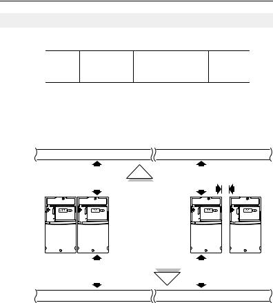
Deutsch-2
Erläuterungen zum Aufstellen des FUs
• Befestigen Sie den FU aufrecht auf einer flachen, senkrechten und ebenen Fläche.
Baugröße |
Schraubengröße |
Anzugsmoment |
DIN-Schiene |
|
B |
M4 |
(#8-32) |
1,56–1,96 Nm |
35 mm |
|
|
|
|
|
C |
M5 |
(#10-24) |
2,45–2,94 Nm |
– |
• Das Kühlgebläse vor Staub und Metallpartikeln schützen.
• FU keiner korrosiven Umgebung aussetzen.
• FU vor Feuchtigkeit und direktem Sonnenlicht schützen.
Beim Aufstellen zu beachtende Mindestabstände
Einbauabmessungen finden Sie auf Seite 21.
120 mm |
120 mm |
25 mm
Nächstes Objekt, das den Luftstrom durch den Kühlkörper und das Gehäuse des FUs blockieren könnte
120 mm 120 mm
Befestigungsoption A Befestigungsoption B
Kein Abstand zwischen FUs erforderlich.
Umgebungs-/Betriebstemperatur
Umgebungstemperatur |
Schutzart |
Beim Aufstellen zu beachtende |
||
|
|
|
Mindestabstände |
|
Minimum |
Maximum |
|
||
|
40 °C |
IP 20/offen |
Befestigungsoption A verwenden |
|
–10 °C |
IP 30/NEMA 1/UL-Typ 1(1) |
Befestigungsoption B verwenden |
||
|
||||
|
50 °C |
IP 20/offen |
Befestigungsoption B verwenden |
|
(1)Nennwert erfordert die Installation des PowerFlex 40P-Optionskits IP 30/NEMA 1/UL-Typ 1.
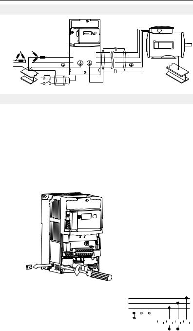
Deutsch-3
Allgemeine Voraussetzungen für die Erdung
|
RUN |
|
REV |
|
FAULT |
R/L1 |
U/T1 |
S/L2 |
V/T2 |
T/L3 |
W/T3 |
SHLD
Entfernen von MOVs
Um Schäden am FU zu vermeiden, sollten die MOV-Verbindungen zur Erde bei Installation des FUs in einem nicht geerdeten Verteilungssystem, in dem die Spannungen zwischen einer der Phasen 125 % der Nenn-Leiter-/Leiter-Spannung übersteigen könnten,
unterbrochen werden. Dazu sind die in den nachstehenden Abbildungen aufgeführten Brücken zu entfernen.
1.Zum Lösen der Schraube, diese gegen den Uhrzeigersinn drehen.
2.Brücke abziehen und aus dem FU-Gehäuse enfernen.
3.Schraube fest ziehen.
Brückenposition
Entfernung des Leiter/Erde-MOV
Three-Phase R/L1
AC Input S/L2
T/L3
|
|
|
|
|
1 |
|
2 |
|
3 |
|
4 |
|||||||||
Jumper |
|
|
|
|||||||||||||||||
|
|
|
|
|
|
|
|
|
|
|
|
|
|
|
|
|
|
|
|
|
|
|
|
|
|
|
|
|
|
|
|
|
|
|
|
|
|
|
|
|
|
|
|
|
|
|
|
|
|
|
|
|
|
|
|
|
|
|
|
|
|
|
Wichtig: Ziehen Sie die Schraube nach dem Entfernen der Brücke fest.

Deutsch-4
Einhaltung der EU-Richtlinien
Einzelheiten zur Einhaltung der Niederspannungsund der EMV-Richtlinie finden Sie im PowerFlex 40P-Benutzerhandbuch.
Sicherungen und Leistungsschalter –
Technische Daten
FU-Nennwerte
Bestellnum- |
Ausgangsnennwerte |
Eingangsnennwerte |
|
Netzstromleitungsschutz |
|
||||
mer(1) |
kW (HP) |
A |
Spannungs- |
kVA |
A |
Sicherun- |
Motorschutzschal- |
Überbrück- |
|
|
bereich |
gen |
ter 140M |
ungsschütze |
|||||
200–240 V AC (±10 %) – Dreiphaseneingang, 0–230-V-Dreiphasenausgang |
|
|
|||||||
22D-B2P3 |
0,4 |
(0,5) |
2,3 |
180–264 |
1,15 |
2,5 |
6 |
140M-C2E-B40 |
100-C07 |
|
|
|
|
|
|
|
|
|
|
22D-B5P0 |
0,75 (1,0) |
5,0 |
180–264 |
2,45 |
5,7 |
10 |
140M-C2E-C10 |
100-C09 |
|
|
|
|
|
|
|
|
|
|
|
22D-B8P0 |
1,5 |
(2,0) |
8,0 |
180–264 |
4,0 |
9,5 |
15 |
140M-C2E-C16 |
100-C12 |
|
|
|
|
|
|
|
|
|
|
22D-B012 |
2,2 |
(3,0) |
12,0 |
180–264 |
5,5 |
15,5 |
25 |
140M-C2E-C16 |
100-C23 |
|
|
|
|
|
|
|
|
|
|
22D-B017 |
3,7 |
(5,0) |
17,5 |
180–264 |
8,6 |
21,0 |
30 |
140M-F8E-C25 |
100-C23 |
|
|
|
|
|
|
|
|
|
|
22D-B024 |
5,5 |
(7,5) |
24,0 |
180–264 |
11,8 |
26,1 |
40 |
140M-F8E-C32 |
100-C37 |
|
|
|
|
|
|
|
|
|
|
22D-B033 |
7,5 |
(10,0) |
33,0 |
180–264 |
16,3 |
34,6 |
60 |
140M-G8E-C45 |
100-C60 |
|
|
|
|
|
|
|
|
|
|
380–480 V AC (±10 %) – Dreiphaseneingang, 0–460-V-Dreiphasenausgang |
|
|
|||||||
22D-D1P4 |
0,4 |
(0,5) |
1,4 |
342–528 |
1,4 |
1,8 |
3 |
140M-C2E-B25 |
100-C07 |
|
|
|
|
|
|
|
|
|
|
22D-D2P3 |
0,75 (1,0) |
2,3 |
342–528 |
2,3 |
3,2 |
6 |
140M-C2E-B40 |
100-C07 |
|
|
|
|
|
|
|
|
|
|
|
22D-D4P0 |
1,5 |
(2,0) |
4,0 |
342–528 |
4,0 |
5,7 |
10 |
140M-C2E-B63 |
100-C09 |
|
|
|
|
|
|
|
|
|
|
22D-D6P0 |
2,2 |
(3,0) |
6,0 |
342–528 |
5,9 |
7,5 |
15 |
140M-C2E-C10 |
100-C09 |
|
|
|
|
|
|
|
|
|
|
22D-D010 |
4,0 |
(5,0) |
10,5 |
342–528 |
10,3 |
13,0 |
20 |
140M-C2E-C16 |
100-C23 |
|
|
|
|
|
|
|
|
|
|
22D-D012 |
5,5 |
(7,5) |
12,0 |
342–528 |
11,8 |
14,2 |
25 |
140M-D8E-C20 |
100-C23 |
|
|
|
|
|
|
|
|
|
|
22D-D017 |
7,5 |
(10,0) |
17,0 |
342–528 |
16,8 |
18,4 |
30 |
140M-D8E-C20 |
100-C23 |
|
|
|
|
|
|
|
|
|
|
22D-D024 |
11,0 (15,0) |
24,0 |
342–528 |
23,4 |
26,0 |
50 |
140M-F8E-C32 |
100-C43 |
|
|
|
|
|
|
|
|
|
|
|
460–600 V AC (±10 %) – Dreiphaseneingang, 0–575-V-Dreiphasenausgang |
|
|
|||||||
|
|
|
|
|
|
|
|
|
|
22D-E1P7 |
0,75 (1,0) |
1,7 |
414–660 |
2,1 |
2,3 |
6 |
140M-C2E-B25 |
100-C09 |
|
|
|
|
|
|
|
|
|
|
|
22D-E3P0 |
1,5 |
(2,0) |
3,0 |
414–660 |
3,65 |
3,8 |
6 |
140M-C2E-B40 |
100-C09 |
|
|
|
|
|
|
|
|
|
|
22D-E4P2 |
2,2 |
(3,0) |
4,2 |
414–660 |
5,2 |
5,3 |
10 |
140M-C2E-B63 |
100-C09 |
|
|
|
|
|
|
|
|
|
|
22D-E6P6 |
4,0 |
(5,0) |
6,6 |
414–660 |
8,1 |
8,3 |
15 |
140M-C2E-C10 |
100-C09 |
|
|
|
|
|
|
|
|
|
|
22D-E9P9 |
5,5 |
(7,5) |
9,9 |
414–660 |
12,1 |
11,2 |
20 |
140M-C2E-C16 |
100-C16 |
|
|
|
|
|
|
|
|
|
|
22D-E012 |
7,5 |
(10,0) |
12,2 |
414–660 |
14,9 |
13,7 |
25 |
140M-C2E-C16 |
100-C23 |
|
|
|
|
|
|
|
|
|
|
22D-E019 |
11,0 (15,0) |
19,0 |
414–660 |
23,1 |
24,1 |
40 |
140M-D8E-C25 |
100-C30 |
|
|
|
|
|
|
|
|
|
|
|
(1)Nennwerte gelten für alle FU-Ausführungen; Schrankmontage (N104), Flanschmontage (F104) und Plattenantrieb (H204).
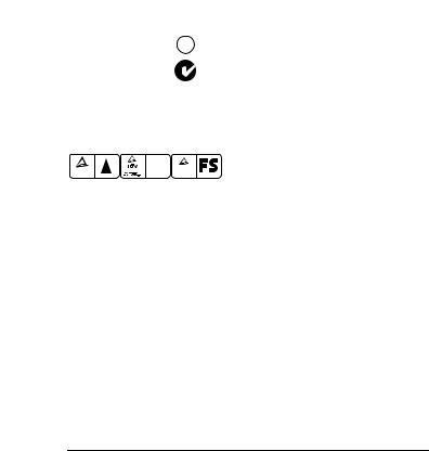
|
|
|
|
|
|
|
|
|
Deutsch-5 |
|
|
|
|
|
|
|
|
|
|
|
|
|
|
|
|
|
|
|
|
|
|
|
Kategorie |
Spezifikation |
|
|
|
|
|
|
|||
Zulassungen |
|
|
|
|
U® L |
|
|
Zugelassen nach UL508C und CAN/CSA-22.2 |
|
|
|
|
|
|
|
US |
|
|
|
||
|
|
|
|
|
C |
|
|
|
||
|
|
|
|
|
|
|
|
Zertifiziert gemäß AS/NZS, 1997, Gruppe 1, Klasse A |
|
|
|
|
|
|
|
|
|
|
|
|
|
|
|
|
|
|
|
|
|
Für alle anwendbaren europäischen Richtlinien |
||
|
|
|
|
|
|
|
|
|
||
|
|
|
|
|
|
|
|
gekennzeichnet |
||
|
|
|
|
|
|
|
|
EMV-Richtlinie (89/336) |
||
|
|
|
|
|
|
|
|
EN 61800-3, EN 50081-1, EN 50082-2 |
||
|
|
|
|
|
|
|
|
Niederspannungsrichtlinie (73/23/EEC) |
||
|
|
|
|
|
|
|
|
EN 50178, EN 60204 |
||
|
|
|
|
|
|
Functional |
Zertifiziert nach EN 954-1, Kategorie 3. |
|
||
|
|
|
|
|
|
Bauart geprüft |
Erfüllt Funktionssicherheit (FS) bei Verwendung |
|||
|
TUV |
|
|
|
TUV |
|
Safety |
|||
|
.. |
|
|
EN 50178 .. |
|
|
|
|
|
|
|
Product Safety |
Production inspected |
Rheinland |
Type approved |
in Verbindung mit der Option DriveGuard Safe-Off |
|||||
|
Rheinland |
EWC |
|
|
|
|
|
|
||
|
|
|
|
|
|
|
|
(Serie B). |
|
|
|
Der FU ist so konstruiert, dass er die entsprechenden Teile der folgenden Spezifikationen erfüllt: |
|||||||||
|
NFPA 70 – US National Electrical Code |
|
|
|
||||||
|
NEMA ICS 3.1 – Sicherheitsnormen für Konstruktion und Leitfaden für Auswahl, Installation |
|||||||||
|
und Betrieb von drehzahlveränderbaren Antriebssystemen. |
|||||||||
|
IEC 146 – International Electrical Code. |
|
|
|
||||||
Schutzvorrich- |
DC-Bus-Überspannungsauslösung |
|
|
|
||||||
tungen |
200–240-V-AC-Eingang: |
|
|
|
405 V DC Busspannung (entspricht 290 V AC |
|||||
|
380–460-V-AC-Eingang: |
|
|
|
Eingangsleitung) |
|||||
|
460–600-V-AC-Eingang: |
|
|
|
810 V DC Busspannung (entspricht 575 V AC |
|||||
|
|
|
|
|
|
|
|
Eingangsleitung) |
||
|
|
|
|
|
|
|
|
1005 V DC Busspannung (entspricht 711 V AC |
||
|
|
|
|
|
|
|
|
Eingangsleitung) |
||
|
DC-Bus-Unterspannungsauslösung |
|
|
|
||||||
|
200–240-V-AC-Eingang: |
|
|
|
210 V DC Busspannung (entspricht 150 V AC |
|||||
|
380–480-V-AC-Eingang: |
|
|
|
Eingangsleitung) |
|||||
|
460–600-V-AC-Eingang |
|
|
|
390-V-DC-Bus (entsprechend 275 V AC am Eingang) |
|||||
|
P042 = 3 „Hochspannung“: |
|
|
|
|
|
||||
|
P042 = 2 „Niederspannung“: |
|
|
487 V DC Busspannung (entspricht 344 V AC |
||||||
|
|
|
|
|
|
|
|
Eingangsleitung) |
||
|
|
|
|
|
|
|
|
390-V-DC-Busspannung (entspricht 275 V AC |
||
|
|
|
|
|
|
|
|
Eingangsleitung) |
||
|
Fehlerfreie Netzausfallüberbrückung: |
100 ms |
|
|
||||||
|
Steuervermögen bei Netzausfall: |
|
|
Mindestens 0,5 s, typisch 2 s |
|
|||||
|
Elektronischer Motorüberlastschutz: |
I2t-Überlastschutz – 150 % für 60 s, 200 % für 3 s |
|
|||||||
|
|
|
|
|
|
|
|
(bietet Schutz gem. Klasse 10) |
||
|
Überstrom: |
|
|
|
200 % Hardwaregrenze, 300 % Impulsgrenze |
|
||||
|
Erdschlussauslösung: |
|
|
|
Phase-Erde am FU-Ausgang |
|
||||
|
Kurzschlussauslösung: |
|
|
|
Phase-Phase am FU-Ausgang |
|
||||
Umgebungsbe- |
Aufstellhöhe: |
|
|
|
Max. 1000 m ohne Leistungsminderung. Über 1000 m |
|
||||
dingungen |
|
|
|
|
|
|
|
Leistungsminderung um 3 % alle 305 m. |
||
|
Maximale Umgebungslufttemperatur |
|
|
|
||||||
|
ohne Leistungsminderung: |
|
|
|
|
|
|
|||
|
IP20, offener Typ: |
|
|
|
–10 bis 50 °C |
|||||
|
IP30, NEMA-Typ 1, UL-Typ 1: |
|
|
–10 bis 40 °C |
||||||
|
Flanschund Plattenmontage: |
|
|
Kühlung: |
–10 bis 40 °C |
|||||
|
|
|
|
|
|
|
|
FU: |
–10 bis 50 °C |
|
|
Kühlmethode |
|
|
|
|
|
|
|||
|
Konvektion: |
|
|
|
0,4-kW-Antriebe sowie alle Flanschund |
|||||
|
Lüfter: |
|
|
|
Plattenantriebe |
|||||
|
|
|
|
|
|
|
|
Alle anderen FU-Nennwerte |
||
|
Lagertemperatur: |
|
|
|
–40 bis 85 °C |
|
||||
|
Atmosphäre: |
|
|
|
Wichtig: Der FU darf nicht in einem Bereich |
|
||||
|
|
|
|
|
|
|
|
aufgestellt werden, in dem die Umgebungsluft |
||
|
|
|
|
|
|
|
|
flüchtige oder korrosive Gase, Dämpfe oder Staub |
||
|
|
|
|
|
|
|
|
enthält. Wenn der FU erst nach einiger Zeit eingebaut |
||
|
|
|
|
|
|
|
|
werden soll, muss er in einem Bereich gelagert |
||
|
|
|
|
|
|
|
|
werden, in dem er keiner korrosiven Atmosphäre |
||
|
|
|
|
|
|
|
|
ausgesetzt ist. |
||
|
Relative Luftfeuchtigkeit: |
|
|
|
0 bis 95 %, nicht kondensierend |
|
||||
|
Erschütterung (Betrieb): |
|
|
|
15 g Spitze über eine Dauer von 11 ms (±1,0 ms) |
|
||||
|
Schwingung (Betrieb): |
|
|
|
1 g Spitze, 5 bis 2000 Hz |
|
||||

Deutsch-6
Kategorie |
Spezifikation |
|
|
Elektrische |
Spannungstoleranz: |
200–240 V ±10 % |
|
Daten |
|
|
380–480 V ±10 % |
|
|
|
460–600 V ±10 % |
|
Frequenztoleranz: |
48–63 Hz |
|
|
Eingangsphasen: |
Dreiphasen-Eingang für gesamten Nennstrom. |
|
|
|
|
Einphasen-Betrieb für 35% des Nennstroms. |
|
Verschiebungsfaktor: |
0,98 über den gesamten Drehzahlbereich |
|
|
Maximaler Kurzschluss-Nennwert: |
100 000 A, symmetrisch |
|
|
Kurzschluss-Istwert: |
Durch AIC-Nennwert der eingebauten Sicherung/des |
|
|
|
|
Leistungsschalters vorgegeben |
|
Transistortyp: |
Bipolar mit isoliertem Gate (IGBT) |
|
Steuerung |
Methode: |
|
Sinuscodierte PWM, Volt/Hertz und sensorloser Vektor |
|
Taktfrequenz: |
2–16 kHz, FU-Nennleistung beruht auf 4 kHz. |
|
|
Frequenzgenauigkeit |
|
|
|
Digitaleingang: |
Innerhalb ±0,05 % der eingestellten |
|
|
Analogeingang: |
Ausgangsfrequenz |
|
|
Innerhalb 0,5 % der maximalen Ausgangsfrequenz, |
||
|
Analogausgang: |
10-Bit-Auflösung |
|
|
±2 % der vollen 10-Bit-Auflösung |
||
|
Drehzahlregelung |
|
|
|
Offener Regelkreis mit |
±1 % der Grunddrehzahl über einen |
|
|
Schlupfkompensation: |
Drehzahlbereich von 80:1 |
|
|
Mit Encoder: |
±0,3 % der Grunddrehzahl über einen |
|
|
|
|
Drehzahlbereich von 80:1 |
|
|
|
±0,05 % der Grunddrehzahl über einen |
|
|
|
Drehzahlbereich von 20:1 |
|
Ausgangsfrequenz: |
0–500 Hz (programmierbar) |
|
|
Wirkungsgrad: |
97,5 % (typisch) |
|
|
Stoppmodi: |
|
Mehrere programmierbare Stoppmodi, wie Rampe, |
|
|
|
Auslauf, DC-Bremse und Rampe bis Stillstand |
|
Beschleunigung/Verzögerung: |
Vier voneinander unabhängig programmierbare |
|
|
|
|
Beschleunigungsund Verzögerungszeiten. |
|
|
|
Jede Zeit in 0,1-s-Inkrementen von 0–600 s |
|
|
|
programmiert werden. |
|
Intermittierende Überlast: |
150 % Überlastfähigkeit für max. 1 Minute |
|
|
|
|
200 % Überlastfähigkeit für max. 3 Sekunden |
|
Elektronischer Motorüberlastschutz |
Schutz der Klasse 10 mit wählbarer |
|
|
|
|
drehzahlempfindlicher Reaktion und |
|
|
|
Abschalt-Überlastverzögerungsfunktion |
|
|
|
bei Aktivierung. |
Steuereingänge |
Digital: |
Bandbreite: |
10 rad/s bei offenem und geschlossenem Regelkreis |
|
|
Anzahl: |
(2) teilprogrammierbar |
|
|
|
(5) programmierbar |
|
|
Strom: |
6 mA |
|
|
Typ |
|
|
|
SRC-Modus: |
18–24 V = EIN, 0–6 V = AUS |
|
|
SNK-Modus: |
0–6 V = EIN, 18–24 V = AUS |
|
Analog: |
Anzahl: |
(2) isoliert, –10 bis 10 V und 4–20 mA |
|
|
Spezifikation |
|
|
|
Auflösung: |
10 Bit |
|
|
0 bis 10 V DC analog: |
100 kOhm Eingangsimpedanz |
|
|
4 bis 20 mA analog: |
250 Ohm Eingangsimpedanz |
|
|
Externer Poti: |
1–10 kOhm, min. 2 Watt |
Encoder |
Typ: |
|
Inkremental, Zweikanal |
|
Versorgung: |
|
12 V, 250 mA. Eingänge mit minimal 12 V, 10 mA |
|
|
|
isoliert mit Differenzialsender, maximal 250 kHz. |
|
Quadratur: |
|
90°, ±27 Grad bei 25° C. |
|
Arbeitszyklus: |
50 %, +10 % |
|
|
Anforderungen: |
Encoder müssen leitungsgesteuert sein, Quadratur |
|
|
|
|
(Zweikanal) oder Impuls (Einkanal), 3,5–26 V DC |
|
|
|
Ausgang, Single-Ended oder differenzial, sowie |
|
|
|
geeignet für eine Versorgung von mindestens |
|
|
|
10 mA pro Kanal. Am Eingang ist Gleichstrom |
|
|
|
mit einer Frequenz von bis zu 250 kHz zulässig. |
|
|
|
Die Encoder-E/A werden automatisch für |
|
|
|
Nennspannungen von 5 V, 12 V und 24 V DC skaliert. |
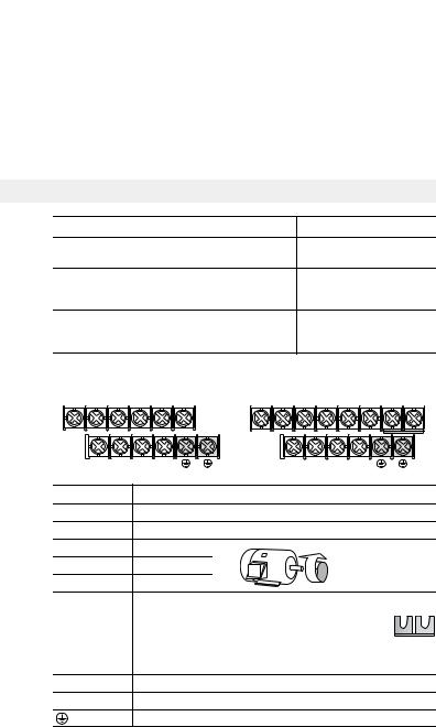
|
|
|
Deutsch-7 |
|
|
|
|
|
|
|
|
|
|
|
Kategorie |
Spezifikation |
|
|
|
Steueraus- |
Relais: |
Anzahl: |
(1) programmierbar, Form C |
|
gänge |
|
|
|
|
|
Spezifikation |
|
|
|
|
|
Ohmsche Last: |
3,0 A bis 30 V DC, 3,0 A bei 125 V, 3,0 A bei 240 V AC |
|
|
|
Induktivlast: |
0,5 A bis 30 V DC, 0,5 A bei 125 V, 0,5 A bei 240 V AC |
|
|
Opto: |
Anzahl: |
(2) programmierbar |
|
|
|
Spezifikation: |
30 V DC, 50 mA, nicht induktiv |
|
|
Analog: |
Anzahl: |
(1) nicht isoliert, 0 bis 10 V oder 4–20 mA |
|
|
|
Spezifikation |
|
|
|
|
Auflösung: |
10 Bit |
|
|
|
0 bis 10 V DC analog: |
1 kOhm min. |
|
|
|
4 bis 20 mA analog: |
525 Ohm max. |
|
Netzanschluss
Verdrahtungsnennwerte |
|
Empfohlener Kupferdraht |
||||
Nicht abgeschirmt, 600 V, 75 °C THHN/THWN |
0,4 mm, isoliert, für |
|||||
trockene Standorte |
||||||
|
|
|
|
|
||
|
|
|
|
|
Anixter OLF-7xxxxx, |
|
Abgeschirmt, 600 V, 75 °C bzw. 90 °C RHH/RHW-2 |
Belden 29501-29507 |
|||||
|
|
|
|
|
oder gleichwertig |
|
Abgeschirmter Kabelkanal mit Nennwert 600 V, |
Anixter 7V-7xxxx-3G |
|||||
Shawflex 2ACD/3ACD |
||||||
75 °C bzw. 90 °C RHH/RHW-2 |
|
|||||
|
oder gleichwertig |
|||||
|
|
|
|
|
||
Klemmenleiste für den Netzanschluss |
|
|||||
Baugröße B |
|
|
Baugröße C |
|||
R/L1 S/L2 |
T/L3 |
U/T1 |
V/T2 W/T3 |
R/L1 |
S/L2 T/L3 U/T1 V/T2 W/T3 P2 P1 |
|
DC- |
DC+ |
BR+ |
BR- |
|
DCDC+ BR+ BR- |
|
Klemme (1) |
|
Beschreibung |
|
|
||
R/L1, S/L2 |
|
1-Phasen-Eingang (2) |
|
|||
R/L1, S/L2, T/L3 |
3-Phasen-Eingang |
|
||||
U/T1 |
|
Zu Motor U/T1 |
|
Zwei Motorkabel |
||
V/T2 |
|
Zu Motor V/T2 |
= |
vertauschen, um |
||
|
Drehrichtung zu |
|||||
|
|
|
|
|
||
W/T3 |
|
Zu Motor W/T3 |
|
ändern. |
||
|
|
DC-Bus-Induktoranschluss (nur bei FUs der Baugröße C). |
||||
|
|
Beim FU der Baugröße C ist bei Anlieferung zwischen den |
||||
P2, P1 |
|
Klemmen P2 und P1 eine Brücke installiert. Entfernen Sie |
||||
|
|
diese Brücke nur, wenn ein DC-Bus-Induktor angeschlossen |
||||
|
|
werden soll. Der FU kann nicht ohne eine angeschlossene |
||||
|
|
Brücke oder einen angeschlossenen Induktor gestartet werden. |
||||
DC+, DC– |
|
DC-Busverbindung |
|
|||
BR+, BR– |
|
Anschluss des Widerstands für den Brems-Chopper |
||||
Schutzerde – PE
(1)Wichtig: Klemmenschrauben können sich während des Transports lösen. Stellen Sie vor dem Einschalten des FUs sicher, dass alle Klemmenschrauben mit dem empfohlenen Drehmoment angezogen sind.
(2)Für Einphasen-Betrieb ist eine Minderung des FU-Nennstroms um 65 % erforderlich.

Deutsch-8
Klemmenleiste für den Netzanschluss – Technische Daten
Baugröß |
Maximaler |
|
Minimaler |
|
e |
Leiterquerschnitt |
(1) |
Leiterquerschnitt (1) |
Moment |
B |
5,3 mm2 (10 AWG) |
1,3 mm2 (AWG 16) |
1,7–2,2 Nm |
|
C |
8,4 mm2 (8 AWG) |
|
1,3 mm2 (AWG 16) |
2,9–3,7 Nm |
(1)Der angegebene Leiterquerschnitt bezeichnet Maximalbzw. Minimalgrößen, die in die Klemmenleiste passen – es handelt sich nicht um Empfehlungen.
Netzeigenschaften
Netzeigenschaften |
Abhilfemaßnahme |
||
|
|
|
|
Niedrige Impedanz (weniger als 1 % Reaktanz) |
• |
Netzdrossel(2) |
|
|
• |
oder Trenntransformator |
|
Größer als 120 kVA Netztransformator |
|||
• oder Businduktor installieren – |
|||
|
|||
|
|
nur bei FUs zwischen 5,5 und |
|
|
|
11 kW (7,5 bzw. 15 HP) |
|
|
|
|
|
Leitung verfügt über |
• |
Netzdrossel |
|
Blindleistungskompensationskondensatoren |
• |
oder Trenntransformator |
|
|
|
installieren |
|
Häufige Netzunterbrechungen |
|
||
|
|
||
|
|
|
|
Kurzfristige Spannungsspitzen von mehr als |
|
|
|
6000 V (Blitzschlag) |
|
|
|
|
|
||
Leiter-Erde-Spannung überschreitet 125 % der |
• MOV-Brücke zu Erde entfernen |
||
normalen Leiter-Leiter-Spannung |
• |
und Trenntransformator mit |
|
|
|
geerdeter Sekundärwicklung |
|
Ungeerdetes Verteilungssystem |
|
||
|
installieren. |
||
|
|
||
|
|
|
|
Offene Delta-Konfiguration (240 V)(1) |
• |
Netzdrossel installieren |
|
(1)Für FUs, die in offenen Delta-Konfigurationen mit einem neutralen System eingesetzt werden, bei dem die mittlere Phase geerdet ist, wird die Phase gegenüber der
in der Mitte der Masse oder Erdung abgenommen Phase als „Hauptzweig“, „Spannungszweig“, „roter Zweig“ o. Ä. bezeichnet. Dieser Zweig sollte im gesamten System jeweils am Anschlusspunkt mit rotem oder orangefarbenem Klebeband gekennzeichnet werden. Der Hauptzweig sollte an der mittleren Phase B der Drossel angeschlossen werden. Die genauen Artikelnummern der Netzdrosseln sind dem PowerFlex 40P-Benutzerhandbuch zu entnehmen.
(2)Bestellinformationen für Zubehörteile sind Anhang B des PowerFlex 40P-Benutzerhandbuch zu entnehmen.
Hinweise zum gemeinsamen Bus und zur Vorladung
Wenn FUs mit interner Vorladung über einen Trennschalter an den gemeinsamen Bus angeschlossen werden, muss ein Hilfskontakt des Trennschalters mit einem Digitaleingang des FUs verbunden werden. Der entsprechende Eingang (Parameter A051–A054) muss auf Option 29, „Precharge Enable“, gesetzt werden. Auf diese Weise wird die erforderliche Vorladungsverriegelung erreicht und der
FU gegen mögliche Schäden beim Anschluss an einen gemeinsamen DC-Bus geschützt.
 Loading...