


 Loading...
20-COMM-H RS-485 HVAC Adapter
Firmware Version 2.xxx
Modbus RTU
Metasys N2
Siemens Building Technologies P1 FLN
User Manual
Important User Information Solid state equipment has operational characteristics differing from those of electromechanical equipment. Safety Guidelines for the Application, Installation and Maintenance of Solid State Controls (Publication SGI-1.1 available from your local Rockwell Automation sales office or online at http:// www.rockwellautomation.com/literature) describes some important differences between solid state equipment and hard-wired electromechanical devices. Because of this difference, and also because of the wide variety of uses for solid state equipment, all persons responsible for applying this equipment must satisfy themselves that each intended application of this equipment is acceptable.
In no event will Rockwell Automation, Inc. be responsible or liable for indirect or consequential damages resulting from the use or application of this equipment.
The examples and diagrams in this manual are included solely for illustrative purposes. Because of the many variables and requirements associated with any particular installation, Rockwell Automation, Inc. cannot assume responsibility or liability for actual use based on the examples and diagrams.
No patent liability is assumed by Rockwell Automation, Inc. with respect to use of information, circuits, equipment, or software described in this manual.
Reproduction of the contents of this manual, in whole or in part, without written permission of Rockwell Automation, Inc. is prohibited.
Throughout this manual, when necessary we use notes to make you aware of safety considerations.
WARNING: Identifies information about practices or
! |
circumstances that can cause an explosion in a hazardous |
|
|
|
environment, which may lead to personal injury or death, property |
|
damage, or economic loss. |
|
|
Important: Identifies information that is critical for successful application and understanding of the product.
ATTENTION: Identifies information about practices or
! |
circumstances that can lead to personal injury or death, property |
|
|
|
damage, or economic loss. Attentions help you identify a hazard, |
|
avoid a hazard, and recognize the consequences. |
|
|
|
|
|
Shock Hazard labels may be located on or inside the equipment |
|
(e.g., drive or motor) to alert people that dangerous voltage may be |
|
present. |
|
|
|
|
|
Burn Hazard labels may be located on or inside the equipment |
|
(e.g., drive or motor) to alert people that surfaces may be at |
|
dangerous temperatures. |
|
|
PowerFlex, SMC Flex, DriveExplorer, DriveExecutive, DPI, DriveTools SP, and SCANport are either trademarks or registered trademarks of Rockwell Automation, Inc.
Metasys is a trademark of Johnson Controls, Inc. Modbus is a trademark of Schneider Automation.
P1 FLN is a trademark of Siemens Building Technologies.
Windows and Microsoft are registered trademarks of Microsoft Corporation.
20-COMM-H RS-485 HVAC Adapter User Manual

Summary of Changes
The information below summarizes the changes made to this manual since its last release (March 2004):
Description of Changes |
Page |
Reformatted document from half size (5.5 x 8.5 in.) to full size (8.5 x 11 in.) |
Throughout |
|
manual |
Added SMC Flex to the list of compatible products, and Metasys N2 is compatible with |
1-2 |
PowerFlex 700VC drive. |
|
Added new Adapter Modbus Register Map section. |
4-2 |
Included information about using Modbus RTU mode to access 16-bit and 32-bit |
4-10 and |
parameters. |
4-12 |
Added new Adapter Parameter Direct Access section. |
4-13 |
Added new Metasys N2 Device Identity subsection. |
5-1 |
Added new “Reference Setup Examples” subsection. |
5-4 |
Added tip about configuring Analog Data Integers (ADIs). |
5-9 |
Added Flashing Red/Green MOD status indicator information. |
8-3 |
Added new Parameter 32 - [RTU Param Mode] to select the 16-bit default mode or |
B-4 |
optional 32-bit mode in which the adapter operates. |
|
20-COMM-H RS-485 HVAC Adapter User Manual
Publication 20COMM-UM009D-EN-P

soc-ii Summary of Changes
20-COMM-H RS-485 HVAC Adapter User Manual
Publication 20COMM-UM009D-EN-P

|
|
Table of Contents |
Preface |
About This Manual |
|
|
Related Documentation . . . . . . . . . . . . . . . . . . . . . . . . . . . . . . . . . |
. . . . . . . . . . . . . . . . . P-1 |
|
Rockwell Automation Support . . . . . . . . . . . . . . . . . . . . . . . . . . . . |
. . . . . . . . . . . . . . . . . P-2 |
|
Conventions Used in This Manual . . . . . . . . . . . . . . . . . . . . . . . . . . |
. . . . . . . . . . . . . . . . P-2 |
Chapter 1 |
Getting Started |
|
|
Components. . . . . . . . . . . . . . . . . . . . . . . . . . . . . . . . . . . . . . . . . . . . |
. . . . . . . . . . . . . . . . 1-1 |
|
Features . . . . . . . . . . . . . . . . . . . . . . . . . . . . . . . . . . . . . . . . . . . . . . . |
. . . . . . . . . . . . . . . . 1-2 |
|
Compatible Products . . . . . . . . . . . . . . . . . . . . . . . . . . . . . . . . . . . . . |
. . . . . . . . . . . . . . . . 1-2 |
|
Required Equipment . . . . . . . . . . . . . . . . . . . . . . . . . . . . . . . . . . . . . |
. . . . . . . . . . . . . . . . 1-3 |
|
Safety Precautions. . . . . . . . . . . . . . . . . . . . . . . . . . . . . . . . . . . . . . . |
. . . . . . . . . . . . . . . . 1-3 |
|
Quick Start . . . . . . . . . . . . . . . . . . . . . . . . . . . . . . . . . . . . . . . . . . . . |
. . . . . . . . . . . . . . . . 1-5 |
|
Status Indicators . . . . . . . . . . . . . . . . . . . . . . . . . . . . . . . . . . . . . . . . |
. . . . . . . . . . . . . . . . 1-6 |
Chapter 2 |
Installing the Adapter |
|
|
Preparing for an Installation . . . . . . . . . . . . . . . . . . . . . . . . . . . . . . . |
. . . . . . . . . . . . . . . . 2-1 |
|
Commissioning the Adapter . . . . . . . . . . . . . . . . . . . . . . . . . . . . . . . |
. . . . . . . . . . . . . . . . 2-1 |
|
Connecting the Adapter to the Drive. . . . . . . . . . . . . . . . . . . . . . . . . |
. . . . . . . . . . . . . . . . 2-3 |
|
Connecting the Adapter to the Network . . . . . . . . . . . . . . . . . . . . . . |
. . . . . . . . . . . . . . . . 2-6 |
|
Applying Power. . . . . . . . . . . . . . . . . . . . . . . . . . . . . . . . . . . . . . . . . |
. . . . . . . . . . . . . . . . 2-7 |
Chapter 3 |
Configuring the Adapter |
|
|
Configuration Tools. . . . . . . . . . . . . . . . . . . . . . . . . . . . . . . . . . . . . . |
. . . . . . . . . . . . . . . . 3-1 |
|
Using the PowerFlex 7-Class HIM . . . . . . . . . . . . . . . . . . . . . . . . . . |
. . . . . . . . . . . . . . . . 3-2 |
|
Setting the Node Address . . . . . . . . . . . . . . . . . . . . . . . . . . . . . . . . . |
. . . . . . . . . . . . . . . . 3-3 |
|
Setting the Network Data Rate . . . . . . . . . . . . . . . . . . . . . . . . . . . . . |
. . . . . . . . . . . . . . . . 3-3 |
|
Setting the Network Parity . . . . . . . . . . . . . . . . . . . . . . . . . . . . . . . . |
. . . . . . . . . . . . . . . . 3-4 |
|
Setting Stop Bits (Modbus RTU only) . . . . . . . . . . . . . . . . . . . . . . . |
. . . . . . . . . . . . . . . . 3-4 |
|
Setting the I/O Configuration . . . . . . . . . . . . . . . . . . . . . . . . . . . . . . |
. . . . . . . . . . . . . . . . 3-5 |
|
Setting a Network Time-out . . . . . . . . . . . . . . . . . . . . . . . . . . . . . . . |
. . . . . . . . . . . . . . . . 3-6 |
|
Setting a Fault Action . . . . . . . . . . . . . . . . . . . . . . . . . . . . . . . . . . . . |
. . . . . . . . . . . . . . . . 3-7 |
|
Resetting the Adapter . . . . . . . . . . . . . . . . . . . . . . . . . . . . . . . . . . . . |
. . . . . . . . . . . . . . . . 3-8 |
|
Viewing the Adapter Status Using Parameters . . . . . . . . . . . . . . . . . |
. . . . . . . . . . . . . . . . 3-9 |
|
Flash Updating the Adapter . . . . . . . . . . . . . . . . . . . . . . . . . . . . . . . |
. . . . . . . . . . . . . . . 3-10 |
Chapter 4 |
Using Modbus RTU |
|
|
Understanding Modbus RTU . . . . . . . . . . . . . . . . . . . . . . . . . . . . . . |
. . . . . . . . . . . . . . . . 4-1 |
|
Adapter Modbus Register Map . . . . . . . . . . . . . . . . . . . . . . . . . . . . . |
. . . . . . . . . . . . . . . . 4-2 |
|
Using the Modbus RTU Point Map for I/O. . . . . . . . . . . . . . . . . . . . |
. . . . . . . . . . . . . . . . 4-4 |
|
Accessing Drive Parameters . . . . . . . . . . . . . . . . . . . . . . . . . . . . . . . |
. . . . . . . . . . . . . . . . 4-9 |
|
Using Broadcast Messages . . . . . . . . . . . . . . . . . . . . . . . . . . . . . . . . |
. . . . . . . . . . . . . . . 4-12 |
|
Adapter Parameter Direct Access . . . . . . . . . . . . . . . . . . . . . . . . . . . |
. . . . . . . . . . . . . . . 4-13 |
Chapter 5 |
Using Metasys N2 |
|
|
Understanding Metasys N2 . . . . . . . . . . . . . . . . . . . . . . . . . . . . . . . . |
. . . . . . . . . . . . . . . . 5-1 |
|
Using the Metasys N2 Point Map for I/O . . . . . . . . . . . . . . . . . . . . . |
. . . . . . . . . . . . . . . . 5-3 |
|
Using Metasys Configurable Objects to Access Parameters. . . . . . . |
. . . . . . . . . . . . . . . . 5-8 |
20-COMM-H RS-485 HVAC Adapter User Manual
Publication 20COMM-UM009D-EN-P

ii Table of Contents
Chapter 6 |
Using Siemens Building Technologies P1 FLN |
|
|
|
Understanding Siemens Building Technologies P1 FLN . . . . . . . . . . . . . . . . . . . . . . . . . |
6-1 |
|
|
Using the P1 |
FLN Point Map for I/O . . . . . . . . . . . . . . . . . . . . . . . . . . . . . . . . . . . . . . . . |
6-5 |
|
Using the P1 |
FLN Point Map to Access Parameters . . . . . . . . . . . . . . . . . . . . . . . . . . . . . |
6-9 |
Chapter 7 |
Using Datalinks with All Protocols |
|
|
Using Datalinks . . . . . . . . . . . . . . . . . . . . . . . . . . . . . . . . . . . . . . . . . . . . . . . . . . . . . . . . . |
7-1 |
|
Using Datalinks with Modbus . . . . . . . . . . . . . . . . . . . . . . . . . . . . . . . . . . . . . . . . . . . . . . |
7-3 |
|
Using Datalinks with Metasys N2 . . . . . . . . . . . . . . . . . . . . . . . . . . . . . . . . . . . . . . . . . . . |
7-4 |
|
Using Datalinks with Siemens P1 FLN . . . . . . . . . . . . . . . . . . . . . . . . . . . . . . . . . . . . . . . |
7-5 |
Chapter 8 |
Troubleshooting |
|
|
Understanding the Status Indicators . . . . . . . . . . . . . . . . . . . . . . . . . . . . . . . . . . . . . . . . . |
8-1 |
|
PORT Status Indicator . . . . . . . . . . . . . . . . . . . . . . . . . . . . . . . . . . . . . . . . . . . . . . . . . . . . |
8-2 |
|
MOD Status Indicator . . . . . . . . . . . . . . . . . . . . . . . . . . . . . . . . . . . . . . . . . . . . . . . . . . . . |
8-2 |
|
NET A Status Indicator . . . . . . . . . . . . . . . . . . . . . . . . . . . . . . . . . . . . . . . . . . . . . . . . . . . |
8-3 |
|
NET B Status Indicator . . . . . . . . . . . . . . . . . . . . . . . . . . . . . . . . . . . . . . . . . . . . . . . . . . . |
8-3 |
|
Viewing Adapter Diagnostic Items . . . . . . . . . . . . . . . . . . . . . . . . . . . . . . . . . . . . . . . . . . |
8-4 |
|
Viewing and Clearing Events. . . . . . . . . . . . . . . . . . . . . . . . . . . . . . . . . . . . . . . . . . . . . . . |
8-6 |
Appendix A |
Specifications |
|
|
Communications . . . . . . . . . . . . . . . . . . . . . . . . . . . . . . . . . . . . . . . . . . . . . . . . . . . . . . . . |
A-1 |
|
Electrical . . . . . . . . . . . . . . . . . . . . . . . . . . . . . . . . . . . . . . . . . . . . . . . . . . . . . . . . . . . . . . |
A-1 |
|
Mechanical. . . . . . . . . . . . . . . . . . . . . . . . . . . . . . . . . . . . . . . . . . . . . . . . . . . . . . . . . . . . . |
A-1 |
|
Environmental . . . . . . . . . . . . . . . . . . . . . . . . . . . . . . . . . . . . . . . . . . . . . . . . . . . . . . . . . . |
A-1 |
|
Regulatory Compliance . . . . . . . . . . . . . . . . . . . . . . . . . . . . . . . . . . . . . . . . . . . . . . . . . . . |
A-2 |
Appendix B |
Adapter Parameters |
|
|
Parameter List . . . . . . . . . . . . . . . . . . . . . . . . . . . . . . . . . . . . . . . . . . . . . . . . . . . . . . . . . . |
B-1 |
Appendix C |
Logic Command/Status Words |
|
|
PowerFlex 7-Class Drives (except PowerFlex 700S) . . . . . . . . . . . . . . . . . . . . . . . . . . . . |
C-1 |
|
PowerFlex 700S Drives . . . . . . . . . . . . . . . . . . . . . . . . . . . . . . . . . . . . . . . . . . . . . . . . . . . |
C-3 |
Glossary
Index
20-COMM-H RS-485 HVAC Adapter User Manual
Publication 20COMM-UM009D-EN-P

Preface
About This Manual
Topic |
Page |
Related Documentation |
P-1 |
Rockwell Automation Support |
P-2 |
Conventions Used in This Manual |
P-2 |
Related Documentation
For: |
Refer to: |
Publication |
DriveExplorer™ |
http://www.ab.com/drives/driveexplorer, and |
— |
|
DriveExplorer online help (installed with the software) |
|
DriveTools™ SP (includes |
http://www.ab.com/drives/drivetools, and |
— |
DriveExecutive™) |
DriveExecutive online help (installed with the software) |
|
HIM |
HIM Quick Reference |
20HIM-QR001 |
PowerFlex® 70/70EC Drive |
PowerFlex 70 User Manual |
20A-UM001 |
|
PowerFlex 70/700 Reference Manual |
PFLEX-RM001 |
|
PowerFlex 70EC/700VC Reference Manual |
PFLEX-RM004 |
PowerFlex® 700/700VC Drive |
PowerFlex 700 User Manual |
20B-UM001 |
PowerFlex® 700 Series B Drive |
PowerFlex 700 Series B User Manual |
20B-UM002 |
|
PowerFlex 70/700 Reference Manual |
PFLEX-RM001 |
|
PowerFlex 70EC/700VC Reference Manual |
PFLEX-RM004 |
PowerFlex® 700H Drive |
PowerFlex 700H Installation Instructions |
PFLEX-IN006 |
|
PowerFlex 700H Programming Manual |
20C-PM001 |
PowerFlex® 700S Drive |
PowerFlex 700S with Phase I Control User Manual |
20D-UM001 |
(Frames 1 through 6) |
PowerFlex 700S with Phase II Control User Manual |
20D-UM006 |
|
PowerFlex 700S Reference Manual |
PFLEX-RM002 |
PowerFlex® 700S Drive |
PowerFlex 700S Installation Instructions |
PFLEX-IN006 |
(Frames 9 and higher) |
PowerFlex 700S with Phase I Control User Manual |
20D-UM001 |
|
PowerFlex 700S with Phase II Control User Manual |
20D-UM006 |
|
PowerFlex 700S Reference Manual |
PFLEX-RM002 |
PowerFlex® 700L Drive |
PowerFlex 700L User Manual |
20L-UM001 |
Modbus RTU Protocol Specification |
www.modicon.com/techpubs/TechPubNew |
PI_MBUS_300.pdf |
You can view or download publications at www.literature.rockwellautomation.com. To order paper copies of technical documentation, contact your local Rockwell Automation distributor or sales representative.
To find your local Rockwell Automation distributor or sales representative, visit www.rockwellautomation.com/locations.
For information such as firmware updates or answers to drive-related questions, go to the Drives Service & Support web site at www.ab.com/ support/abdrives and click on the “Downloads” or “Knowledgebase” link.
20-COMM-H RS-485 HVAC Adapter User Manual
Publication 20COMM-UM009D-EN-P

P-2 About This Manual
Rockwell Automation
Support
Rockwell Automation, Inc. offers support services worldwide, with over 75 sales/support offices, over 500 authorized distributors, and over 250 authorized systems integrators located through the United States alone. In addition, Rockwell Automation, Inc. representatives are in every major country in the world.
Conventions Used in This
Manual
Local Product Support
Contact your local Rockwell Automation, Inc. representative for:
•Sales and order support
•Product technical training
•Warranty support
•Support service agreements
Technical Product Assistance
For technical assistance, please review the information in Chapter 8, Troubleshooting, first. If you still have problems, then access the Allen-Bradley Technical Support web site at www.ab.com/support/abdrives or contact Rockwell Automation, Inc.
The following conventions are used throughout this manual:
•Parameter names are shown in the format Parameter xx - [*]. The xx represents the parameter number. The * represents the parameter name— for example Parameter 01 - [DPI Port].
•Menu commands are shown in bold type face and follow the format Menu > Command. For example, if you read “Select File > Open,” you should click the File menu and then click the Open command.
•The firmware release is displayed as FRN X.xxx. The “FRN” signifies Firmware Release Number. The “X” is the major release number. The “xxx” is the minor update number.
•This manual provides information about the adapter and using it with PowerFlex 7-Class (Architecture-Class) drives. The adapter can be used with other products that support a DPI™ adapter, such as SMC™ Flex. Refer to the documentation for your product for specific information about how it works with the adapter.
20-COMM-H RS-485 HVAC Adapter User Manual
Publication 20COMM-UM009D-EN-P
Chapter 1
Getting Started
The adapter is a communication option intended for installation into a PowerFlex 7-Class drive. It can also be used with other Allen-Bradley products that support a DPI™ (Drive Peripheral Interface) adapter.
Topic |
Page |
Components |
1-1 |
Features |
1-2 |
Compatible Products |
1-2 |
Required Equipment |
1-3 |
Safety Precautions |
1-3 |
Quick Start |
1-5 |
Status Indicators |
1-6 |
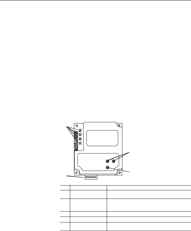
Components Figure 1.1 Components of the Adapter
|
|
|
|
|
|
Item |
Part |
Description |
|
Status Indicators |
Four LEDs that indicate the status of the DPI, the adapter, and |
|
|
network connection. Refer to Chapter 8, Troubleshooting. |
|
DPI Connector |
A 20-pin, single-row shrouded male header. An Internal Interface |
|
|
cable is connected to this connector and a connector on the |
|
|
drive. |
|
Terminal Block |
A 6-screw terminal block connects the adapter to the network. |
|
Node Address Switches |
Two switches set the node address. |
|
Network Selector Switch |
Switch selects the network protocol to which the adapter |
|
|
operates. |
20-COMM-H RS-485 HVAC Adapter User Manual
Publication 20COMM-UM009D-EN-P

1-2 Getting Started
Features |
The adapter features include: |
|
|
|
|
|
|
|
||||
|
• Typical mounting in a PowerFlex 7-Class drive using captive screws to |
|||||||||||
|
secure and ground the adapter to the drive. |
|
|
|
|
|||||||
|
• Compatibility with various configuration tools to configure the adapter |
|||||||||||
|
and connected drive. The tools include the PowerFlex HIM on the drive, |
|||||||||||
|
and drive-configuration software such as DriveExplorer (version 2.01 or |
|||||||||||
|
higher) or DriveExecutive (version 3.01 or higher). |
|
|
|||||||||
|
• Status indicators that report the status of the drive communications, the |
|||||||||||
|
adapter, and network. They are visible when the drive cover is open or |
|||||||||||
|
closed. |
|
|
|
|
|
|
|
|
|
|
|
|
• Parameter-configurable I/O (Logic Command/Reference and up to four |
|||||||||||
|
pairs of Datalinks) to meet application requirements. |
|
|
|||||||||
|
• User-defined fault actions to determine how the adapter and PowerFlex |
|||||||||||
|
drive respond to communication disruptions on the network. |
|||||||||||
|
• Switches to allow setting a node address before applying power to the |
|||||||||||
|
drive. Alternatively, you can disable the switches and use a parameter to |
|||||||||||
|
configure the node address. |
|
|
|
|
|
|
|
||||
|
• A switch lets you select from the following three network protocols: |
|||||||||||
|
– |
Modbus™ RTU |
|
|
|
|
|
|
|
|
|
|
|
– |
Metasys™ N2 |
|
|
|
|
|
|
|
|
|
|
|
– Siemens Building Technologies P1 FLN™ |
|
|
|
||||||||
|
• Available read/write access to parameters, allowing parameter values to |
|||||||||||
|
be configured and monitored over the network. |
|
|
|
||||||||
|
• Support for DPI routing, enabling access to any networked PowerFlex |
|||||||||||
|
7-Class drive (with 20-COMM-H adapter) using DriveExplorer (version |
|||||||||||
|
2.01 or higher) to monitor and configure that drive and its connected |
|||||||||||
|
peripherals. |
|
|
|
|
|
|
|
|
|
|
|
Compatible Products |
DPI is a second generation peripheral communication interface. The adapter |
|||||||||||
|
is compatible with Allen-Bradley PowerFlex 7-Class drives and other |
|||||||||||
|
products that support DPI. At the time of publication, compatible products |
|||||||||||
|
include: |
|
|
|
|
|
|
|
|
|
|
|
|
|
|
|
|
|
|
|
|
|
|||
|
Network |
|
Compatible PowerFlex Drives |
|
SMC |
|||||||
|
Protocol |
70 |
700EC |
|
700VC |
700H |
|
700S |
7000 |
Flex |
|
|
|
Modbus RTU |
|
|
|
|
|
|
|
|
|
||
|
Metasys N2 |
|
|
|
|
|
|
|
|
|
|
|
|
Siemens P1 FLN |
|
|
|
|
|
|
|
|
|
|
|
The PowerFlex 70/700 are used for examples in this manual. Refer to a DPI
Host product’s user manual for additional information.
20-COMM-H RS-485 HVAC Adapter User Manual
Publication 20COMM-UM009D-EN-P
Getting Started |
1-3 |
|
|
Required Equipment |
Equipment Shipped with the Adapter |
|
When you unpack the adapter, verify that the package includes: |
|
One adapter |
|
A 2.54 cm (1 in.) and a 15.24 cm (6 in.) Internal Interface cable (only |
|
one cable is needed to connect the adapter to the drive) |
User-Supplied Equipment
To install and configure the adapter, you must supply:
A small flathead screwdriver
Network-specific cable to connect the adapter to the network. Refer to the network-specific documentation for the cable recommendations and requirements.
Configuration tool, such as:
|
– PowerFlex 7-Class HIM (20-HIM-*) |
|
– DriveExplorer (version 2.01 or higher) |
|
– DriveExecutive stand-alone software (version 3.01 or higher) or |
|
bundled with the DriveTools SP suite (version 1.01 or higher) |
|
– Third-party network configuration software |
|
A PC connection to the network |
Safety Precautions |
Please read the following safety precautions carefully. |
!
!
!
!
ATTENTION: Risk of injury or death exists. The PowerFlex drive may contain high voltages that can cause injury or death. Remove all power from the PowerFlex drive, and then verify power has been discharged before installing or removing an adapter.
ATTENTION: Risk of injury or equipment damage exists. Only personnel familiar with drive and power products and the associated machinery should plan or implement the installation, start up, configuration, and subsequent maintenance of the product using an adapter. Read and understand this entire manual before proceeding. Failure to comply may result in injury and/or equipment damage.
ATTENTION: Risk of equipment damage exists. The adapter contains ESD (Electrostatic Discharge) sensitive parts that can be damaged if you do not follow ESD control procedures. Static control precautions are required when handling the adapter. If you are unfamiliar with static control procedures, refer to
Guarding Against Electrostatic Damage (publication 8000-4.5.2).
ATTENTION: Risk of injury or equipment damage exists. If the adapter is transmitting control I/O to the drive, the drive may fault when you reset the adapter. Determine how your drive will respond before resetting an adapter.
20-COMM-H RS-485 HVAC Adapter User Manual
Publication 20COMM-UM009D-EN-P
1-4 Getting Started
!
!
!
!
!
ATTENTION: Risk of injury or equipment damage exists.
Parameter 15 - [Comm Flt Action] lets you determine the action of the adapter and connected drive if communications are disrupted. By default, this parameter faults the drive. You can set this parameter so that the drive continues to run. Precautions should be taken to ensure that the setting of this parameter does not create a risk of injury or equipment damage. When commissioning the drive, verify that your system responds correctly to various situations (for example, a disconnected cable).
ATTENTION: Risk of injury or equipment damage exists.
Parameter 11 - [Network Timeout] lets you determine how long it will take the adapter to detect network communication losses. By default, this parameter sets the timeout to ten seconds. It can be set so that the duration is shorter, longer, or disabled. Take precautions to ensure that the setting does not create a risk of injury or equipment damage. When commissioning the drive, verify that your system responds correctly to various situations (for example, a disconnected cable).
ATTENTION: Risk of injury or equipment damage exists. DPI or SCANport host products must not be directly connected via 1202 cables. Unpredictable behavior due to timing and other internal procedures can result if two or more hosts are connected in this manner.
ATTENTION: Risk of injury or equipment damage exists. When a system is configured for the first time, there may be unintended or incorrect machine motion. Disconnect the motor from the machine or process during initial system testing.
ATTENTION: Risk of injury or equipment damage exists. The examples in this publication are intended solely for purposes of example. There are many variables and requirements with any application. Rockwell Automation, Inc. does not assume responsibility or liability (to include intellectual property liability) for actual use of the examples shown in this publication.
20-COMM-H RS-485 HVAC Adapter User Manual
Publication 20COMM-UM009D-EN-P

Getting Started |
1-5 |
|
|
Quick Start |
This section is provided to help experienced users quickly start using the |
|||
|
adapter. If you are unsure how to complete a step, refer to the referenced |
|||
|
chapter. |
|
|
|
|
|
|
|
|
|
Step |
Action |
Refer to… |
|
|
1 |
Review the safety precautions for the adapter. |
Throughout This Manual |
|
|
2 |
Verify that the PowerFlex drive is properly installed. |
Drive User Manual |
|
|
3 |
Commission the adapter. |
Chapter 2, |
|
|
|
Select the network protocol using the adapter Network Selector |
Installing the Adapter |
|
|
|
|
||
|
|
switch. Set a unique node address using the adapter Node |
|
|
|
|
Address switches or set both switches to “0” and configure the |
|
|
|
|
node address later using an adapter parameter. |
|
|
|
4 |
Install the adapter. |
Chapter 2, |
|
|
|
Verify that the PowerFlex drive and network are not powered. |
Installing the Adapter |
|
|
|
|
||
|
|
Then, connect the adapter to the network using a network-specific |
|
|
|
|
cable and to the drive using the Internal Interface cable. Use the |
|
|
|
|
captive screws to secure and ground the adapter to the drive. |
|
|
|
5 |
Apply power to the adapter. |
Chapter 2, |
|
|
|
A. The adapter receives power from the drive. Verify that the |
Installing the Adapter |
|
|
|
|
||
|
|
|
adapter and network are installed correctly and then turn on the |
|
|
|
|
network and apply power to the drive. The status indicators |
|
|
|
|
should be green. If they flash red, there is a problem. Refer to |
|
|
|
|
Chapter 8, Troubleshooting. |
|
|
|
B. Configure/verify key drive parameters. |
|
|
|
6 |
Configure the adapter for your application. |
Chapter 3, |
|
|
|
Set adapter parameters for the following functions as required by |
Configuring the Adapter |
|
|
|
|
||
|
|
your application: |
|
|
|
|
• Node address, data rate, and parity |
|
|
|
|
• |
I/O configuration |
|
|
|
• |
Fault actions |
|
|
7 |
Set up the master device to communicate with the adapter. |
Instruction manual for |
|
|
|
Use a network tool to configure the master device on the network. |
your network tool |
|
20-COMM-H RS-485 HVAC Adapter User Manual
Publication 20COMM-UM009D-EN-P

1-6 Getting Started
Status Indicators |
The adapter uses four status indicators to report its operating status. They |
|
can be viewed on the adapter or through the drive cover |
|
(Figure 1.2). |
|
Figure 1.2 Status Indicators (location on drive may vary) |
Item |
Name |
|
PORT |
|
|
|
MOD |
|
|
|
NET A |
|
|
|
NET B |
|
|
After installing the adapter and applying power to the drive, refer to Start-Up Status Indications on page 2-7 for possible start-up status indications and their descriptions.
20-COMM-H RS-485 HVAC Adapter User Manual
Publication 20COMM-UM009D-EN-P

Chapter 2
Installing the Adapter
This chapter provides instructions for installing the adapter in a PowerFlex 7-Class drive.
Topic |
Page |
Preparing for an Installation |
2-1 |
Commissioning the Adapter |
2-1 |
Connecting the Adapter to the Drive |
2-3 |
Connecting the Adapter to the Network |
2-6 |
Applying Power |
2-7 |
Preparing for an Installation |
Before installing the adapter, verify that you have all required equipment. |
||
|
Refer to Required Equipment on page 1-3. |
||
Commissioning the Adapter |
To commission the adapter, you must set a unique node address and select a |
||
|
network protocol. |
||
|
Important: New settings are recognized only when power is applied to the |
||
|
|
|
adapter or it is reset. If you change a switch setting, cycle power |
|
|
|
or reset the adapter to activate the changes. |
|
|
|
|
|
! |
ATTENTION: Risk of equipment damage exists. The adapter |
|
|
contains ESD (Electrostatic Discharge) sensitive parts that can be |
||
|
|
|
damaged if you do not follow ESD control procedures. Static |
|
|
|
|
control precautions are required when handling the adapter. If you are unfamiliar with static control procedures, refer to
Guarding Against Electrostatic Damage (publication 8000-4.5.2).
Important: To guard against device malfunction, it is recommended wear a grounding wrist strap when installing the adapter.
20-COMM-H RS-485 HVAC Adapter User Manual
Publication 20COMM-UM009D-EN-P
2-2 Installing the Adapter
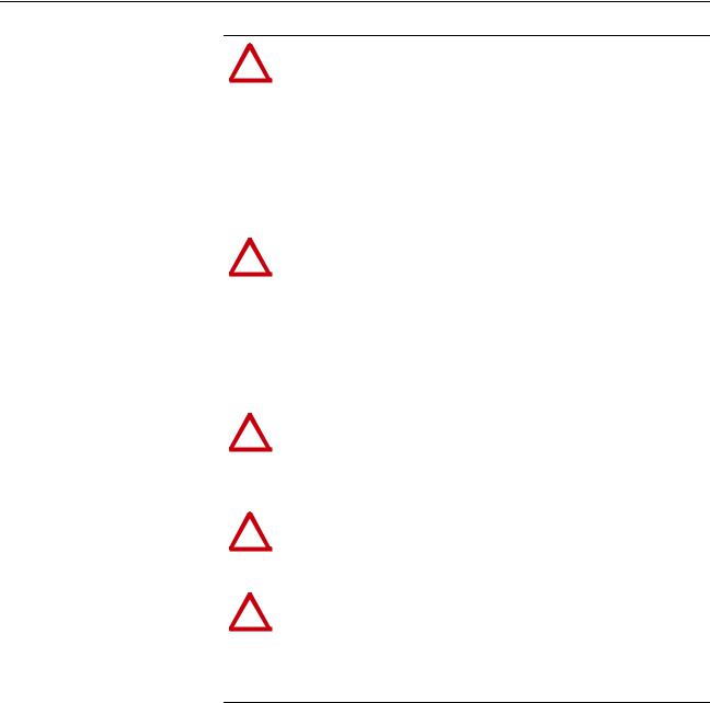
1.Set the adapter’s node address by rotating the node address switches to the desired value for each digit.
Important: Each node on the network must have a unique address.
Figure 2.1 Setting the Node Address
2 |
3 |
|
2 |
3 |
1 |
|
4 |
1 |
4 |
0 |
|
5 |
0 |
5 |
9 |
|
6 |
9 |
6 |
8 |
7 |
|
8 |
7 |
Setting |
Description |
|
01 |
– 99 |
Node address used by the adapter. |
00 |
(Default) |
If network protocols are capable of handling a node address of 0 or node |
|
|
addresses higher than 99, these addresses can be configured by setting the |
|
|
switches to 00 and then setting Parameter 03 - [Net Addr Cfg] to the |
|
|
desired network node address. |
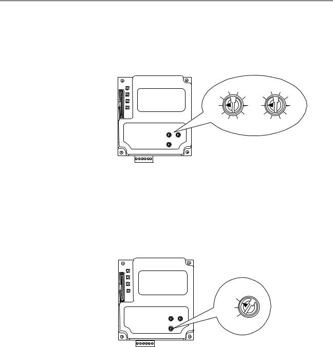
2.Set the network protocol switch.
Figure 2.2 Setting the Network Protocol
RTU
N2
P1
Setting |
Description |
RTU (Default) |
Modbus RTU |
N2 |
Metasys N2 |
P1 |
Siemens Building Technologies P1 FLN |
The switch settings can be verified using a PowerFlex HIM, DriveExplorer software, or DriveExecutive software, and viewing Diagnostic Device Item numbers 40-42 (page 8-5).
20-COMM-H RS-485 HVAC Adapter User Manual
Publication 20COMM-UM009D-EN-P

Installing the Adapter |
2-3 |
|
|
Connecting the Adapter to the Drive
ATTENTION: Risk of injury or death exists. The PowerFlex
!drive may contain high voltages that can cause injury or death.
Remove power from the drive, and then verify power has been discharged before installing or removing the adapter.
1.Remove power from the drive and network.
2.Use static control precautions.
3.Remove the drive cover or open the drive door.
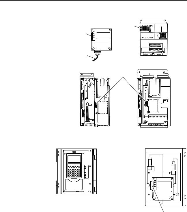
4.Connect the Internal Interface cable to the DPI port on the drive and then to the DPI connector on the adapter (see Figure 2.3).
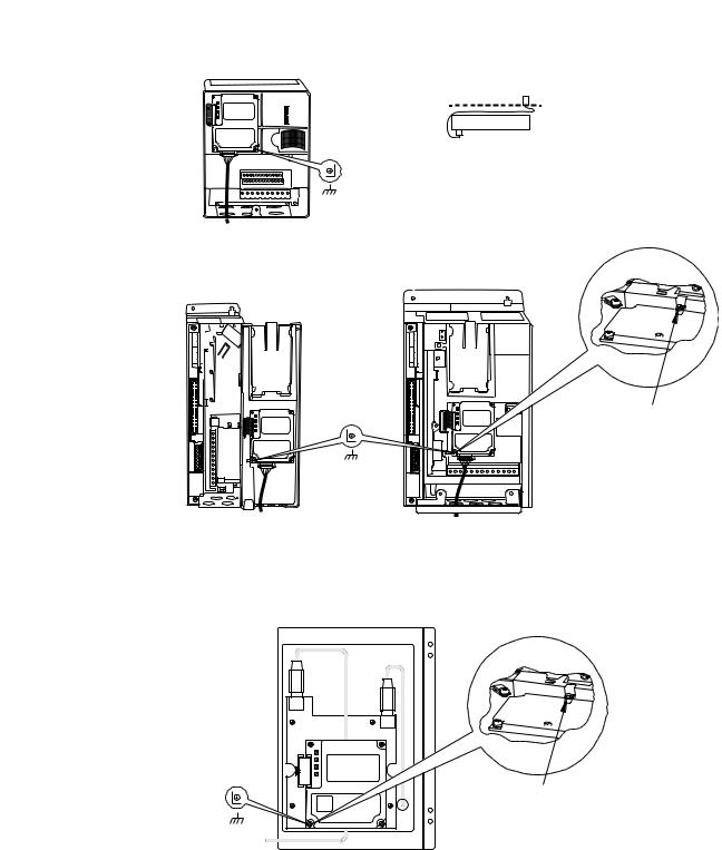
5.Secure and ground the adapter to the drive (see Figure 2.4) by doing the following:
–On a PowerFlex 70 drive, fold the Internal Interface cable behind the adapter and mount the adapter on the drive using the four captive screws.
–On a PowerFlex 700, PowerFlex 700H or PowerFlex 700S drive, mount the adapter on the drive using the four captive screws.
Important: Tighten all screws to properly ground the adapter. Recommended torque is 0.9 N•m (8.0 lb•in).
20-COMM-H RS-485 HVAC Adapter User Manual
Publication 20COMM-UM009D-EN-P
2-4 Installing the Adapter
Figure 2.3 DPI Ports and Internal Interface Cables
20-COMM-H Adapter |
|
|
PowerFlex 70 - All Frames
PowerFlex 700 Frames 0 and 1 |
PowerFlex 700 Frames 2 and Larger |
PowerFlex 700S Frames 0 and 1 |
PowerFlex 700S Frames 2 through 6 |
HIM panel opens to allow access to DPI interface. To open panel, remove screws on left side of HIM panel and swing open.
X2
X1 |
|
|
|
|
|
|
|
|
|
|
|
|
|
|
|
|
|
|
|
|
|
|
|
|
|
|
|
|
|
|
|
|
|
|
|
|
|
|
|
|
|
|
|
|
|
|
|
|
|
|
|
|
|
|
|
|
|
|
|
|
|
|
|
|
|
|
|
|
|
|
|
|
|
|
|
|
|
|
|
|
|
|
|
|
|
|
|
|
|
|
|
|
|
|
|
|
|
|
|
|
|
|
|
|
|
|
|
|
|
|
|
|
|
|
|
|
|
|
|
|
|
|
|
|
|
|
|
|
|
|
|
|
|
|
|
|
|
|
|
|
|
|
|
|
|
|
|
|
|
|
|
|
|
|
|
|
|
|
|
|
|
|
|
|
|
|
|
|
|
|
|
|
|
|
PowerFlex 700H Frames 9 and Larger |
|
|
|
|
|
|
|
|
|
|
|
|
|
||
|
|
|
PowerFlex 700S Frames 9 and Larger |
|
|
|
|
|
|
|
|
|
|
|
||||
|
|
|
|
|
|
|
|
|
|
|
|
|
|
|
|
|||
Item |
Description |
|
|
|
|
|
|
|
|
|
|
|
|
|
|
|||
|
15.24 cm (6 in.) Internal Interface cable |
|
|
|
|
|
|
|
|
|
|
|
|
|
||||
|
|
|
|
|
|
|
|
|
|
|
|
|
|
|
|
|||
|
DPI Connector |
|
|
|
|
|
|
|
|
|
|
|
|
|
||||
|
|
|
|
|
|
|
|
|
|
|
|
|
|
|
|
|||
|
Ethernet cable |
|
|
|
|
|
|
|
|
|
|
|
|
|
||||
|
|
|
|
|
|
|
|
|
|
|
|
|
|
|
|
|||
|
2.54 cm (1 in.) Internal Interface cable |
|
|
|
|
|
|
|
|
|
|
|
|
|
||||
|
|
|
|
|
|
|
|
|
|
|
|
|
|
|
|
|
|
|
20-COMM-H RS-485 HVAC Adapter User Manual
Publication 20COMM-UM009D-EN-P
Installing the Adapter |
2-5 |
|
|
Figure 2.4 Mounting and Grounding the Adapter
0.9 N•m
(8.0 lb•in)
4 Places
PowerFlex 70 - All Frame Sizes
(Adapter mounts in drive.)
0.9 N•m
(8.0 lb•in)
4 Places
Drive
Adapter
Internal Interface Cable folded behind the adapter and in front of the drive.
Ground Tab Detail
Verify metal ground tab is bent 90° and is under the adapter before tightening screw. After tightening the screw, verify continuity exists between the head of the screw and drive ground.
PowerFlex 700 Frames 0 and 1 |
PowerFlex 700 Frames 2 and Larger |
PowerFlex 700S Frames 0 and 1 |
PowerFlex 700S Frames 2 through 6 |
(Adapter mounts on door.) |
(Adapter mounts in drive.) |
|
Ground Tab Detail |
X2
X1
0.9 N•m
(8.0 lb•in)
4 Places
PowerFlex 700H Frames 9 and Larger PowerFlex 700S Frames 9 and Larger (Adapter mounts behind HIM panel.)
Verify metal ground tab is bent 90° and is under the adapter before tightening screw. After tightening the screw, verify continuity exists between the head of the screw and drive ground.
20-COMM-H RS-485 HVAC Adapter User Manual
Publication 20COMM-UM009D-EN-P

2-6 Installing the Adapter
Connecting the Adapter to the Network
ATTENTION: Risk of injury or death exists. The PowerFlex
!drive may contain high voltages that can cause injury or death.
Remove power from the drive, and then verify power has been discharged before installing or removing the adapter.
1.Remove power from the network and drive.
2.Use static control precautions.
3.Connect an RS-485 cable to the network, and route it through the bottom of the PowerFlex drive (Figure 2.4).
4.Connect a six-pin linear plug to the RS-485 cable. (See Figure 2.5 for the terminal definitions.)
Figure 2.5 Typical Network Connections
|
Node 1 |
|
Node 2 |
|
Node "n" |
|||
TERMA |
B |
COM SHIELDGND |
TERMA |
B |
COM SHIELDGND |
TERMA |
B |
COM SHIELDGND |
|
|
|
|
|
|
|
|
|
|
|
|
|
|
|
|
|
|
|
|
|
|
|
|
|
|
|
|
|
|
|
|
|
|
|
|
|
|
|
|
|
|
|
|
|
|
|
|
|
|
|
|
|
|
|
|
|
|
|
|
|
|
|
|
|
|
|
|
|
|
|
|
|
|
|
|
|
|
|
|
|
|
|
|
|
|
|
|
|
|
|
|
|
|
|
|
|
|
|
|
|
|
|
|
|
|
|
|
|
|
|
|
|
|
|
|
|
|
|
|
|
|
|
|
|
|
|
|
|
|
|
|
|
|
|
|
|
|
|
|
|
|
|
|
|
|
|
|
|
|
|
|
|
|
|
|
|
|
|
|
|
|
|
|
|
|
|
|
|
|
|
|
|
|
|
|
|
|
|
|
|
|
|
|
|
|
|
|
|
|
|
|
|
|
|
|
|
|
|
|
|
|
|
|
|
|
|
|
|
|
|
|
|
|
|
|
|
Terminal |
Signal |
Function |
||||||||||||||||||||||||||||
TERM |
Termination (1) |
Signal RC Termination |
||||||||||||||||||||||||||||
A |
Signal A |
TxRxD- |
||||||||||||||||||||||||||||
B |
Signal B |
TxRxD+ |
||||||||||||||||||||||||||||
COM |
Common |
Signal Common |
||||||||||||||||||||||||||||
SHIELD |
Shield |
Shield RC Termination |
||||||||||||||||||||||||||||
GND |
Ground (2) |
Shield GND Termination |
||||||||||||||||||||||||||||
(1)Jumper terminals TERM and A on the adapter at end of the RS-485 network. This enables a built-in RC termination network on the adapter.
(2)The shield must be grounded at a single point on the network (jumper terminals SHIELD and GND).
A 3-wire network using Belden 3106A cable or equivalent is recommended for Modbus RTU applications and shown in Figure 2.3 above. A 2-wire network using Belden 3105A cable or equivalent (COM terminal is not connected) can also be used for most applications. However, a 3-wire network is more robust in noisy environments.
For Metasys N2 or Siemens P1 FLN applications, refer to published guidelines from Johnson Controls or Siemens Building Technologies respectively.
20-COMM-H RS-485 HVAC Adapter User Manual
Publication 20COMM-UM009D-EN-P
Installing the Adapter |
2-7 |
|
|
Applying Power
ATTENTION: Risk of equipment damage, injury, or death
!exists. Unpredictable operation may occur if you fail to verify
that parameter settings are compatible with your application. Verify that settings are compatible with your application before applying power to the drive.
Install the drive cover or close the drive door, and apply power to the drive. The adapter receives its power from the connected drive. When you apply power to the adapter for the first time, its topmost “PORT” status indicator should be steady green after an initialization. If it is red, there is a problem. Refer to Chapter 8, Troubleshooting.
Start-Up Status Indications
Status indicators for the drive and communications adapter can be viewed on the front of the drive (Figure 2.6) after power has been applied. Possible start-up status indications are shown in Table 2.A.
Figure 2.6 Drive and Adapter Status Indicators (location on drive may vary)
PORT
MOD
 NET A
NET A
NET B
STS
Table 2.A Drive and Adapter Start-Up Status Indications
Item |
Name |
Color |
State |
|
Description |
|
|
|
|
Drive |
STS Indicator |
STS (Status)
Green |
Flashing |
Drive ready but not running, and no faults are present. |
|
Steady |
Drive running, no faults are present. |
Yellow |
Flashing, |
An inhibit condition exists – the drive cannot be started. |
|
Drive Stopped |
Check drive Parameter 214 - [Start Inhibits]. |
|
Flashing, Drive |
An intermittent type 1 alarm condition is occurring. |
|
Running |
Check drive Parameter 211 - [Drive Alarm 1]. |
|
Steady, |
A continuous type 1 alarm condition exists. Check drive |
|
Drive Running |
Parameter 211 - [Drive Alarm 1]. |
Red |
Flashing |
A fault has occurred. |
|
Steady |
A non-resettable fault has occurred. |
|
|
|
20-COMM-H RS-485 HVAC Adapter User Manual
Publication 20COMM-UM009D-EN-P

2-8 Installing the Adapter
Item |
Name |
Color |
State |
|
Description |
|
|
|
|
Adapter |
Status Indicators |
|
PORT |
Green |
Flashing |
|
Normal Operation. The adapter is establishing an I/O |
|
|
|
|
|
connection to the drive. It will turn solid green or red. |
|
|
|
Steady |
|
Normal Operation. The adapter is properly connected |
|
|
|
|
|
and communicating with the drive |
|
MOD |
Green |
Flashing |
|
Normal Operation. The adapter is operating but is not |
|
|
|
|
|
transferring I/O data. |
|
|
|
Steady |
|
Normal Operation. The adapter is operating and |
|
|
|
|
|
transferring I/O data. |
|
NET A |
Green |
Flashing |
|
Normal Operation. The adapter is properly connected |
|
|
|
|
|
but does not have an I/O connection. |
|
|
|
Steady |
|
Normal Operation. The adapter is properly connected |
|
|
|
|
|
and communicating on the network. |
|
NET B |
Green |
Off |
|
Normal Operation. The adapter is properly connected |
|
|
|
|
|
but is idle. |
|
|
|
Flashing |
|
Normal Operation. The adapter is properly connected |
|
|
|
|
|
and transmitting data packets on the network. |
Configuring/Verifying Key Drive Parameters
The PowerFlex 7-Class drive can be separately configured for the control and Reference functions in various combinations. For example, you could set the drive to have its control come from a peripheral or terminal block with the Reference coming from the network. Or you could set the drive to have its control come from the network with the Reference coming from another peripheral or terminal block. Or you could set the drive to have both its control and Reference come from the network.
The following steps in this section assume that the drive will receive the
Logic Command and Reference from the network.
1.Use drive Parameter 090 - [Speed Ref A Sel] to set the drive speed Reference to “22” (DPI Port 5).
2.If digital inputs are not used, change drive Parameters 361 - [Dig In1 Sel] through 366 - [Dig In6 Sel] to “0” (Not Used).
3.Verify that drive Parameter 213 - [Speed Ref Source] is reporting that the source of the Reference to the drive is “22” (DPI Port 5). This ensures that any Reference commanded from the network can be monitored by using drive Parameter 002 - [Commanded Speed]. If a problem occurs, this verification step provides the diagnostic capability to determine whether the drive/adapter or the network is the cause.
20-COMM-H RS-485 HVAC Adapter User Manual
Publication 20COMM-UM009D-EN-P

Chapter 3
Configuring the Adapter
This chapter provides instructions and information for setting the parameters in the adapter.
Topic |
Page |
Configuration Tools |
3-1 |
Using the PowerFlex 7-Class HIM |
3-2 |
Setting the Node Address |
3-3 |
Setting the Network Data Rate |
3-3 |
Setting the Network Parity |
3-4 |
Setting Stop Bits (Modbus RTU only) |
3-4 |
Setting the I/O Configuration |
3-5 |
Setting a Network Time-out |
3-6 |
Setting a Fault Action |
3-7 |
Resetting the Adapter |
3-8 |
Viewing the Adapter Status Using Parameters |
3-9 |
Flash Updating the Adapter |
3-10 |
For a list of parameters, refer to Appendix B, Adapter Parameters. For definitions of terms in this chapter, refer to the Glossary.
Configuration Tools |
The adapter stores parameters and other information in its own non-volatile |
||
|
memory. You must, therefore, access the adapter to view and edit its |
||
|
parameters. The following tools can be used to access the adapter |
||
|
parameters: |
|
|
|
|
|
|
|
Tool |
Refer to… |
|
|
PowerFlex HIM |
page 3-2 |
|
|
DriveExplorer Software |
http://www.ab.com/drives/driveexplorer, or |
|
|
(version 2.01 or higher) |
DriveExplorer online help (installed with the software) |
|
|
DriveExecutive Software |
http://www.ab.com/drives/drivetools, or |
|
|
(version 3.01 or higher) |
DriveExecutive online help (installed with the software) |
|
20-COMM-H RS-485 HVAC Adapter User Manual
Publication 20COMM-UM009D-EN-P

3-2 Configuring the Adapter
Using the PowerFlex 7-Class
HIM
If your drive has either an LED or LCD HIM (Human Interface Module), it can be used to access parameters in the adapter as shown below. It is recommended that you read through the steps for your HIM before performing the sequence. For additional information, refer to your PowerFlex Drive User Manual or the HIM Quick Reference card.
Using an LED HIM
Step |
Key(s) |
Example Screens |
|||||||||
1. |
Press ALT and then Sel (Device) to display |
|
Device |
||||||||
|
the Device Screen. |
ALT |
Sel |
||||||||
2. |
Press the Up Arrow or Down Arrow to scroll |
|
or |
|
|
|
|
|
|
|
|
|
to the adapter. Letters represent files in the |
|
|
|
|
|
|
|
|
|
|
|
drive, and numbers represent ports. The |
|
|
|
|
|
|
|
|
|
|
|
|
|
|
|
|
|
|
|
|
|
|
|
adapter is usually connected to port 5. |
|
|
|
|
|
|
|
|
|
|
3.Press the Enter key to enter your selection. A parameter database is constructed, and then the first parameter is displayed.
4.Edit the parameters using the same techniques that you use to edit drive parameters.
Using an LCD HIM
Step |
Key(s) |
Example Screens |
|||||||||
1. |
In the main menu, press the Up Arrow or |
|
|
|
|
|
|
|
|
|
|
|
Down Arrow to scroll to Device Select. |
or |
|
F-> |
Stopped |
|
Auto |
|
|||
2. |
Press Enter to enter your selection. |
|
|
|
|
|
|
0.00 |
Hz |
|
|
|
|
|
|
|
Main Menu: |
|
|
|
|||
3. |
Press the Up Arrow or Down Arrow to scroll |
|
|
|
|
|
|
|
|
||
or |
|
Diagnostics |
|
|
|
||||||
|
to the adapter (20-COMM-H). |
|
Parameter |
|
|
|
|||||
|
|
|
|
|
|
|
|
|
|||
4. |
Press Enter to select the adapter. A |
|
|
|
|
|
Device Select |
|
|
|
|
|
parameter database is constructed, and |
|
|
|
|
|
|
|
|
|
|
|
|
|
|
|
|
|
|
|
|
|
|
|
then the main menu for the adapter is |
|
|
|
|
|
Port 5 Device |
|
|
|
|
|
displayed. |
|
|
|
|
|
20-COMM-H |
|
|
|
|
|
|
|
|
|
|
|
|
|
|
||
5. |
Edit the parameters using the same |
|
|
|
|
|
Main Menu: |
|
|
|
|
|
techniques that you use to edit drive |
|
|
|
|
|
Diagnostics |
|
|
|
|
|
parameters. |
|
|
|
|
|
Parameter |
|
|
|
|
|
|
|
|
|
|
|
Device Select |
|
|
|
|
|
|
|
|
|
|
|
|
|
|
|
|
|
|
|
|
|
|
|
|
|
|
|
|
NOTE: LCD HIM screens are shown throughout this chapter for example configuration procedures.
20-COMM-H RS-485 HVAC Adapter User Manual
Publication 20COMM-UM009D-EN-P

Configuring the Adapter |
3-3 |
|
|
Setting the Node Address |
If the Node Address switches on the adapter are set to “00,” the value of |
|
Parameter 03 - [Net Addr Cfg] determines the node address. |
|
1. Set the value of Parameter 03 - [Net Addr Cfg] to a unique node |
address.
Figure 3.1 Example Net Addr Cfg 1 Screen
Port 5 Device |
|
Default = 1 |
|
|
|
||
20-COMM-H |
|
|
|
Parameter #: 03 |
|
|
|
Net Addr Cfg |
|
|
|
1 |
|
0 <> 247 |
|
|
|
|
|
|
|
|
|
2. Reset the adapter (see Resetting the Adapter on page 3-8). The actual node address is then displayed by Parameter 04 - [Net Addr Act].
Setting the Network Data Rate The data rate at which the adapter operates varies based on the type of network and your network configuration. Refer to the following table.
Network |
Possible Data Rates |
Modbus RTU |
4800, 9600, 19200, 38400 |
Metasys N2 |
9600 |
Siemens Building Technologies P1 FLN |
4800, 9600 |
1.Set the value of Parameter 05 - [Net Rate Cfg] to the data rate at which your network is operating.
Figure 3.2 Example Net Rate Cfg Screen
Port 5 Device |
|
Value |
Baud |
|
20-COMM-H |
|
0 |
4800 |
|
|
1 |
9600 (default) |
||
Parameter #: 05 |
|
|||
|
2 |
19200 |
||
Net Rate Cfg |
|
|||
|
3 |
38400 |
||
1 |
|
|
||
|
|
|
|
|
9600 |
|
|
|
|
|
|
|
|
|
2.Reset the adapter (see Resetting the Adapter on page 3-8). The actual data rate is then displayed by Parameter 06 - [Net Rate Act].
20-COMM-H RS-485 HVAC Adapter User Manual
Publication 20COMM-UM009D-EN-P

3-4 Configuring the Adapter
Setting the Network Parity
Setting Stop Bits (Modbus RTU only)
The parity that the adapter uses to verify data integrity varies based on the type of network and your network configuration. Refer to the following table.
Network |
Possible Types of Parity |
Modbus RTU |
None, Even, or Odd |
Metasys N2 |
None |
Siemens Building Technologies P1 FLN |
None |
1.Set the value of Parameter 07 - [Net Parity Cfg] to the type of parity that is used on the network.
Figure 3.3 Example Network Parity Screen
Port 5 Device |
|
Value |
Type of Parity |
|
20-COMM-H |
|
0 |
None (default) |
|
|
1 |
Odd |
||
Parameter #: 07 |
|
|||
|
2 |
Even |
||
Net Parity Cfg |
|
|||
|
|
|
||
0 |
|
|
|
|
None |
|
|
|
|
|
|
|
|
|
2.Reset the adapter (see Resetting the Adapter on page 3-8). The actual network parity is then displayed by Parameter 08 - [Net Parity Act].
Parameter 30 - [Stop Bits Cfg] enables you to set 1 or 2 stop bits for the Modbus RTU network protocol. When the adapter rotary switch is set to “N2” or “P1,” the Stop Bits Cfg value is ignored and does not transfer to read-only Parameter 09 - [Stop Bits Act] on power-up or reset (N2 and P1 are fixed at 1 stop bit).
1.Set the value of Parameter 30 - [Stop Bits Cfg].
Figure 3.4 Example Stop Bits Screen
Port 5 Device |
|
Value |
Type of Stop Bit |
|
20-COMM-H |
|
0 |
1-bit (default) |
|
|
1 |
2-bits |
||
Parameter #: 30 |
|
|||
|
|
|
||
Stop Bits Cfg |
|
|
|
|
0 |
|
|
|
|
1-bit |
|
|
|
|
|
|
|
|
|
2.Reset the adapter (see Resetting the Adapter on page 3-8). The actual stop bits is then displayed by Parameter 09 - [Stop Bits Act].
20-COMM-H RS-485 HVAC Adapter User Manual
Publication 20COMM-UM009D-EN-P

Configuring the Adapter |
3-5 |
|
|
Setting the I/O
Configuration
The I/O configuration determines the data that is sent to and from the drive. Logic Command/Status, Reference/Feedback, and Datalinks may be enabled or disabled. A “1” enables the I/O. A “0” disables the I/O.
1.Set the bits in Parameter 16 - [DPI I/O Cfg].
Figure 3.5 Example DPI I/O Cfg Screen
Port 5 Device
20-COMM-H
Parameter #: 16 DPI I/O Cfg
x x x x x x x x x x x 0 0 0 0 Cmd/Ref b00
Bit |
Description |
0 |
Logic Command/Reference (Default) |
1 |
Datalink A |
2 |
Datalink B |
3 |
Datalink C (not used with Metasys N2 |
4 |
Datalink D (not used with Metasys N2 |
5 - 15 |
Not Used |
Bit 0 is the right-most bit. In Figure 3.5, it is highlighted and equals “1.”
2.If Logic Command/Reference is enabled, configure the parameters in the drive to accept the Logic Command and Reference from the adapter. For example, set Parameter 90 - [Speed Ref A Sel] in a PowerFlex 70 or 700 drive to “22” (DPI Port 5) so that the drive uses the Reference from the adapter. Also, verify that the mask parameters (for example, Parameter 276 - [Logic Mask]) in the drive are configured to receive the desired logic from the adapter. Refer to the documentation for your drive for details.
3.If you enabled one or more Datalinks, configure parameters in the drive to determine the source and destination of data in the Datalink(s). For example, configure the Datalinks in PowerFlex 70 and 700 drives by setting Parameters 300 - [Data In A1] to 317 - [Data Out D2]. Also, ensure that this adapter is the only adapter using the enabled Datalink(s).
4.Reset the adapter (see Resetting the Adapter on page 3-8).
The adapter is ready to send and receive I/O. The following chapters provide information about basic data transfer for each type of protocol.
Network |
Refer to… |
Modbus RTU |
Chapter 4, Using Modbus RTU |
Metasys N2 |
Chapter 5, Using Metasys N2 |
Siemens Building Technologies P1 FLN |
Chapter 6, Using Siemens Building Technologies P1 FLN |
For details about using Datalinks for all types of networks, refer to Chapter 7, Using Datalinks with All Protocols.
20-COMM-H RS-485 HVAC Adapter User Manual
Publication 20COMM-UM009D-EN-P

3-6 Configuring the Adapter
Setting a Network Time-out The network timeout sets an interval within which the adapter must communicate with its master. If this time is exceeded, the adapter determines a loss of network communications has occurred and responds with the action specified in Parameter 15 - [Comm Flt Action].
By default, the timeout is set to ten (10) seconds. You can increase or decrease this value. Alternatively, you can set the value to zero (0) so that the adapter does not detect communication losses.
ATTENTION: Risk of injury or equipment damage exists.
!Parameter 11 - [Network Timeout] lets you determine how
long it will take your adapter to detect network communication losses. By default, this parameter sets the timeout to ten (10) seconds. You can set it so that the duration is shorter, longer, or disabled. Take precautions to ensure that the setting does not create a risk of injury or equipment damage. When commissioning the drive, verify that your system responds correctly to various situations (for example, a disconnected cable).
Set the network timeout in Parameter 11 - [Network Timeout].
Figure 3.6 Example Network Timeout Screen
Port 5 Device |
|
Default = 10 seconds |
|
20-COMM-H |
|
|
|
Parameter #: 11 |
|
|
|
Network Timeout |
Sec |
|
|
10 |
|
|
|
0 <> 180 |
|
|
|
|
|
|
|
Changes to this parameter take effect immediately. A reset is not required.
20-COMM-H RS-485 HVAC Adapter User Manual
Publication 20COMM-UM009D-EN-P
Configuring the Adapter |
3-7 |
|
|
Setting a Fault Action |
By default, when I/O communications are disrupted (for example, a cable is |
|
disconnected), the drive responds by faulting if it is using I/O from the |
|
network. You can configure a different response to disrupted I/O |
|
communication using Parameter 15 - [Comm Flt Action]. |
|
|
|
ATTENTION: Risk of injury or equipment damage exists. |
!Parameter 15 - [Comm Flt Action] lets you determine the action
of the adapter and connected drive if I/O communications are disrupted. By default, this parameter faults the drive. You can set this parameter so that the drive continues to run. Precautions should be taken to ensure that the setting of this parameter does not create a risk of injury or equipment damage. When commissioning the drive, verify that your system responds correctly to various situations (for example, a disconnected cable).
Changing the Fault Action
Set the value of Parameter 15 - [Comm Flt Action] to the desired response:
Value |
Action |
Description |
0 |
Fault |
The drive is faulted and stopped. (Default) |
1 |
Stop |
The drive is stopped, but not faulted. |
2 |
Zero Data |
The drive is sent 0 for output data. (The command word and Reference are |
|
|
set to zero.) This does not command a stop. |
3 |
Hold Last |
The drive continues in its present state. |
4 |
Send Flt Cfg |
The drive is sent the data that you set in the fault configuration parameters |
|
|
(Parameters 18 - [Flt Cfg Logic] through 27 - [Flt Cfg D2 In]). |
Figure 3.7 Example Fault Action Screen
Port 5 Device
20-COMM-H
Parameter #: 15
Comm Flt Action
0
Fault
Changes to this parameter takes effect immediately. A reset is not required.
Setting the Fault Configuration Parameters
If you set Parameter 15 - [Comm Flt Action] to “Send Flt Cfg,” the values in the following parameters are sent to the drive after an I/O communications fault occurs. You must set these parameters to values required by your application.
Parameter |
Name |
Description |
25 |
Flt Cfg Logic |
A 16-bit value sent to the drive for Logic Command. |
26 |
Flt Cfg Ref |
A 32-bit value (0 – 4294967295) sent to the drive as a Reference or |
|
|
Datalink. |
27 – 34 |
Flt Cfg x1 In |
|
|
or |
Important: If the drive uses a 16-bit Reference or 16-bit Datalinks, the most |
|
Flt Cfg x2 In |
significant word of the value must be set to zero (0) or a fault will occur. |
Changes to these parameters take effect immediately. A reset is not required.
20-COMM-H RS-485 HVAC Adapter User Manual
Publication 20COMM-UM009D-EN-P

3-8 Configuring the Adapter
Resetting the Adapter |
Changes to switch settings and some adapter parameters require that you |
|
reset the adapter before the new settings take effect. You can reset the |
|
adapter by cycling power to the drive or by using Parameter 14 - [Reset |
|
Module]. |
|
|
|
ATTENTION: Risk of injury or equipment damage exists. If the |
!adapter is transmitting control I/O to the drive, the drive may fault
when you reset the adapter. Determine how your drive will respond before resetting a connected adapter.
Set Parameter 14 - [Reset Module] to “1” (Reset Module).
Figure 3.8 Example Reset Module Screen
Port 5 Device |
|
Value |
Description |
|
20-COMM-H |
|
0 |
Ready (Default) |
|
|
|
|
1 |
Reset Module |
Parameter #: 14 |
|
|||
Reset Module |
|
2 |
Set Defaults |
|
1 |
|
|
|
|
Reset Module |
|
|
|
|
|
|
|
|
|
When you enter “1” (Reset Module), the adapter will be immediately reset. When you enter “2” (Set Defaults), the adapter will set all adapter parameters to their factory-default values. After performing a Set Defaults, enter “1” (Reset Module) so that the new values take effect. The value of this parameter will be restored to “0” (Ready) after the adapter is reset.
20-COMM-H RS-485 HVAC Adapter User Manual
Publication 20COMM-UM009D-EN-P
Loading...