


2094-EN02D-M01-S0
Table of contents
 Loading...
Safety Reference Manual
Kinetix 6200 and Kinetix 6500
Safe Torque-off Multi-axis Servo Drives
Catalog Numbers 2094-SE02F-M00-S0, 2094-EN02D-M01-S0
Important User Information
IMPORTANT
Solid-state equipment has operational characteristics differing from those of electromechanical equipment. Safety
Guidelines for the Application, Installation and Maintenance of Solid State Controls (publication SGI-1.1
your local Rockwell Automation® sales office or online at http://www.rockwellautomation.com/literature/
important differences between solid-state equipment and hard-wired electromechanical devices. Because of this difference,
and also because of the wide variety of uses for solid-state equipment, all persons responsible for applying this equipment
must satisfy themselves that each intended application of this equipment is acceptable.
In no event will Rockwell Automation, Inc. be responsible or liable for indirect or consequential damages resulting from the
use or application of this equipment.
The examples and diagrams in this manual are included solely for illustrative purposes. Because of the many variables and
requirements associated with any particular installation, Rockwell Automation, Inc. cannot assume responsibility or
liability for actual use based on the examples and diagrams.
No patent liability is assumed by Rockwell Automation, Inc. with respect to use of information, circuits, equipment, or
software described in this manual.
Reproduction of the contents of this manual, in whole or in part, without written permission of Rockwell Automation,
Inc., is prohibited.
Throughout this manual, when necessary, we use notes to make you aware of safety considerations.
available from
) describes some
WARNING: Identifies information about practices or circumstances that can cause an explosion in a hazardous environment,
which may lead to personal injury or death, property damage, or economic loss.
ATTENTION: Identifies information about practices or circumstances that can lead to personal injury or death, property
damage, or economic loss. Attentions help you identify a hazard, avoid a hazard, and recognize the consequence.
SHOCK HAZARD: Labels may be on or inside the equipment, for example, a drive or motor, to alert people that dangerous
voltage may be present.
BURN HAZARD: Labels may be on or inside the equipment, for example, a drive or motor, to alert people that surfaces may
reach dangerous temperatures.
Identifies information that is critical for successful application and understanding of the product.
Allen-Bradley, Kinetix, RSLogix, TechConnect, Rockwell Automation, and Rockwell Software are trademarks of Rockwell Automation, Inc.
Trademarks not belonging to Rockwell Automation are property of their respective companies.
This manual contains new and updated information.
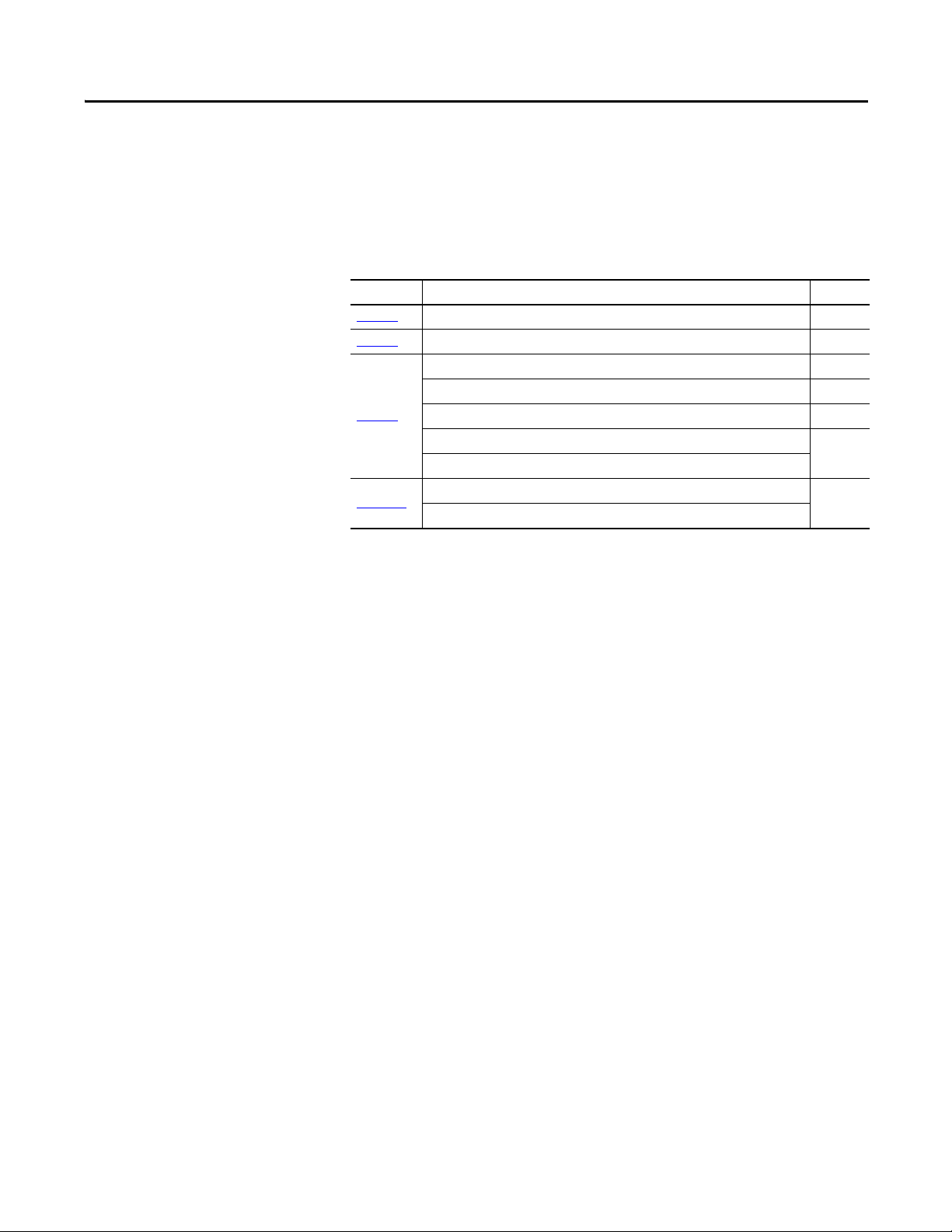
Summary of Changes
New and Updated Information
This revision includes new material for the 2090-K6CK-D44S0 low-profile
connector kit and 2090-CS0DSDS-AAxx interface cable for cascading the safe
torque-off signals from drive-to-drive.
Section Topic Page
Chapter 2
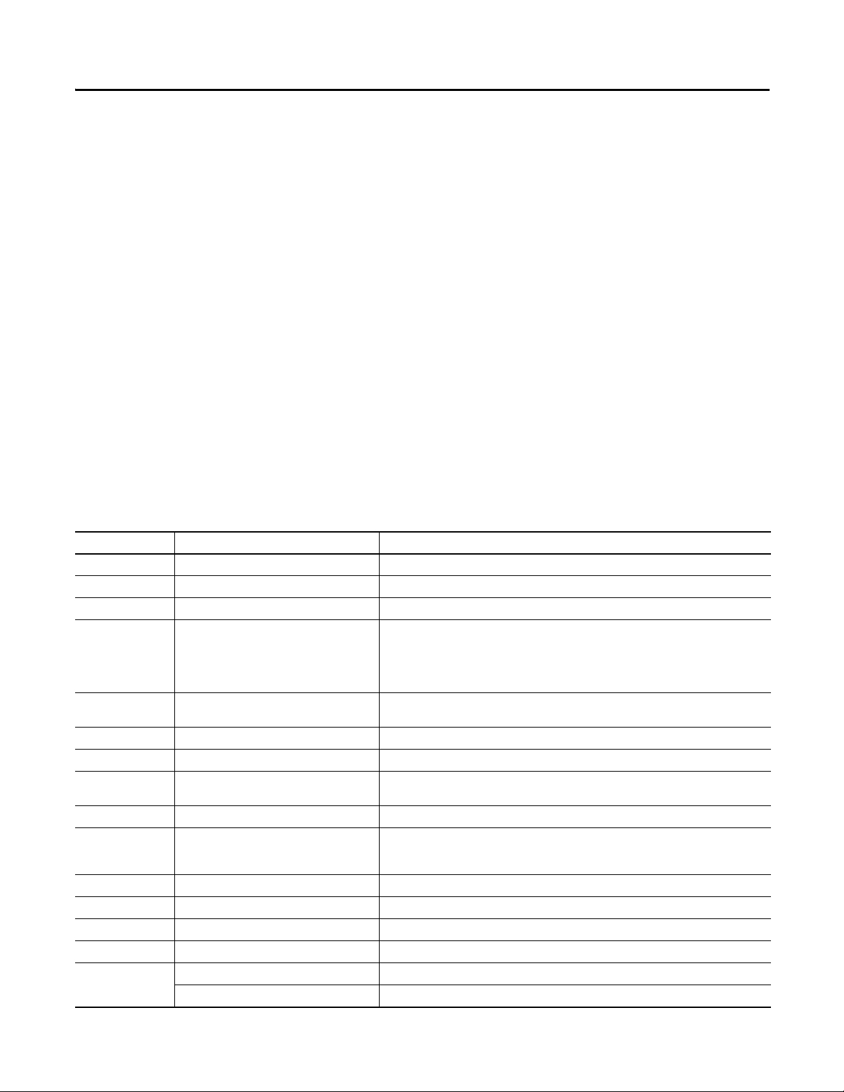
Chapter 3 Updated Safety Input Wiring diagram to use 24VPWR (IOD-14, IOD-15) 22
Chapter 4
Appendix A
Added a description and connection diagram for the 2090-K6CK-D44S0 connector kit. 16
Updated Cascaded Connections diagram to use 24VPWR (IOD-14, IOD-15) 27
Updated 2090-K6CK-D44M wiring examples to use 24VPWR (IOD-14, IOD-15) 28
Added 2090-K6CK-D44S0 wiring examples 29…30
Added Kinetix 6200/6500 cascading safe torque-off cable example
Added 2090-CS0DSDS-AAxx cable pinout diagram and termination table
Updated General Specifications with value for reset time
Added footnotes to clarify the effect cascading drives has on reaction time and reset time
31
37
Rockwell Automation Publication 2094-RM002B-EN-P - May 2012 3

Summary of Changes
Notes:
4 Rockwell Automation Publication 2094-RM002B-EN-P - May 2012

Safety Concept
Table of Contents
Preface
About This Publication. . . . . . . . . . . . . . . . . . . . . . . . . . . . . . . . . . . . . . . . . . . . . 7
Who Should Use This Manual . . . . . . . . . . . . . . . . . . . . . . . . . . . . . . . . . . . . . . 7
Terminology. . . . . . . . . . . . . . . . . . . . . . . . . . . . . . . . . . . . . . . . . . . . . . . . . . . . . . . 7
Additional Resources . . . . . . . . . . . . . . . . . . . . . . . . . . . . . . . . . . . . . . . . . . . . . . . 8
Chapter 1
Introduction. . . . . . . . . . . . . . . . . . . . . . . . . . . . . . . . . . . . . . . . . . . . . . . . . . . . . . . 9
Safety Certification. . . . . . . . . . . . . . . . . . . . . . . . . . . . . . . . . . . . . . . . . . . . . . . . . 9
Important Safety Considerations . . . . . . . . . . . . . . . . . . . . . . . . . . . . . . 10
Safety Category 4 Performance Definition. . . . . . . . . . . . . . . . . . . . . . 10
Stop Category 0 Definition. . . . . . . . . . . . . . . . . . . . . . . . . . . . . . . . . . . . 10
Performance Level and Safety Integrity Level (SIL) CL3 . . . . . . . . . 11
PFD and PFH Definitions . . . . . . . . . . . . . . . . . . . . . . . . . . . . . . . . . . . . . . . . 11
PFD and PFH Data . . . . . . . . . . . . . . . . . . . . . . . . . . . . . . . . . . . . . . . . . . . . . . 11
Safe State . . . . . . . . . . . . . . . . . . . . . . . . . . . . . . . . . . . . . . . . . . . . . . . . . . . . . . . . 12
Safety Reaction Time. . . . . . . . . . . . . . . . . . . . . . . . . . . . . . . . . . . . . . . . . . . . . 12
Contact Information If Failure Occurs. . . . . . . . . . . . . . . . . . . . . . . . . . . . . 12
Automatic Drive Replacement (ADR) . . . . . . . . . . . . . . . . . . . . . . . . . . . . . 12
Installation and Wiring
Safe Torque-off I/O Signals
Chapter 2
Introduction. . . . . . . . . . . . . . . . . . . . . . . . . . . . . . . . . . . . . . . . . . . . . . . . . . . . . 13
General Safety Information . . . . . . . . . . . . . . . . . . . . . . . . . . . . . . . . . . . . . . . 13
Power Supply Requirements . . . . . . . . . . . . . . . . . . . . . . . . . . . . . . . . . . . . . . 14
Wiring the Safety Connections. . . . . . . . . . . . . . . . . . . . . . . . . . . . . . . . . . . . 14
Using the 2090-K6CK-D44M Low-profile Connector Kit . . . . . . 14
Using the 2090-K6CK-D44S0 Low-profile Connector Kit . . . . . . 16
Using the Motion-allowed Plug. . . . . . . . . . . . . . . . . . . . . . . . . . . . . . . . 17
Terminal Connections . . . . . . . . . . . . . . . . . . . . . . . . . . . . . . . . . . . . . . . . . . . 18
Chapter 3
Introduction. . . . . . . . . . . . . . . . . . . . . . . . . . . . . . . . . . . . . . . . . . . . . . . . . . . . . 19
Inputs. . . . . . . . . . . . . . . . . . . . . . . . . . . . . . . . . . . . . . . . . . . . . . . . . . . . . . . . . . . 19
Discrepancy Time . . . . . . . . . . . . . . . . . . . . . . . . . . . . . . . . . . . . . . . . . . . . 20
Reset Input (Reset_In). . . . . . . . . . . . . . . . . . . . . . . . . . . . . . . . . . . . . . . . 23
Outputs . . . . . . . . . . . . . . . . . . . . . . . . . . . . . . . . . . . . . . . . . . . . . . . . . . . . . . . . . 23
Safe Stop Output (SS_Out) . . . . . . . . . . . . . . . . . . . . . . . . . . . . . . . . . . . 23
Safe Stop Reset . . . . . . . . . . . . . . . . . . . . . . . . . . . . . . . . . . . . . . . . . . . . . . . 25
Safe Stop Wiring Example . . . . . . . . . . . . . . . . . . . . . . . . . . . . . . . . . . . . . . . . 26
Rockwell Automation Publication 2094-RM002B-EN-P - May 2012 5

Table of Contents
Chapter 4
Multi-axis Cascaded Systems
Troubleshooting the Safe Torque-off
Drive
Specifications
Introduction . . . . . . . . . . . . . . . . . . . . . . . . . . . . . . . . . . . . . . . . . . . . . . . . . . . . . 27
Cascaded Configurations . . . . . . . . . . . . . . . . . . . . . . . . . . . . . . . . . . . . . . . . . 27
Safe Stop Wiring Examples. . . . . . . . . . . . . . . . . . . . . . . . . . . . . . . . . . . . . . . . 28
2090-K6CK-D44M Connector Kit Examples. . . . . . . . . . . . . . . . . . . 28
2090-K6CK-D44S0 Connector Kit Examples . . . . . . . . . . . . . . . . . . 29
Chapter 5
Introduction . . . . . . . . . . . . . . . . . . . . . . . . . . . . . . . . . . . . . . . . . . . . . . . . . . . . . 33
Nonrecoverable Faults . . . . . . . . . . . . . . . . . . . . . . . . . . . . . . . . . . . . . . . . . . . . 33
Fault Recovery . . . . . . . . . . . . . . . . . . . . . . . . . . . . . . . . . . . . . . . . . . . . . . . . . . . 33
Input and Output Faults . . . . . . . . . . . . . . . . . . . . . . . . . . . . . . . . . . . . . . . . . . 34
Fault Codes and Descriptions . . . . . . . . . . . . . . . . . . . . . . . . . . . . . . . . . . . . . 34
Status Attributes . . . . . . . . . . . . . . . . . . . . . . . . . . . . . . . . . . . . . . . . . . . . . . . . . 35
Guard Status Attributes . . . . . . . . . . . . . . . . . . . . . . . . . . . . . . . . . . . . . . . 35
Guard Fault Attributes. . . . . . . . . . . . . . . . . . . . . . . . . . . . . . . . . . . . . . . . 36
Appendix A
Introduction . . . . . . . . . . . . . . . . . . . . . . . . . . . . . . . . . . . . . . . . . . . . . . . . . . . . . 37
General Specifications . . . . . . . . . . . . . . . . . . . . . . . . . . . . . . . . . . . . . . . . . . . . 37
Certifications . . . . . . . . . . . . . . . . . . . . . . . . . . . . . . . . . . . . . . . . . . . . . . . . . . . . 38
Index
6 Rockwell Automation Publication 2094-RM002B-EN-P - May 2012
Preface
About This Publication
This manual explains how the Kinetix® 6200 and Kinetix 6500 drives can be used
in Safety Integrity Level (SIL) CL3, Performance Level [PLe], or Category
(CAT) 4 applications. It describes the safety requirements, including PFD and
PFH values and application verification information, and provides information
on configuring and troubleshooting the Kinetix 6200 and Kinetix 6500 drives
with safe torque-off functionality.
Who Should Use This Manual
Use this manual if you are responsible for designing, configuring, or
troubleshooting safety applications that use Kinetix 6200 or Kinetix 6500 drives
with safe torque-off functionality.
You must have a basic understanding of electrical circuitry and familiarity with
Kinetix 6200 and Kinetix 6500 drives. You must also be trained and experienced
in the creation, operation, and maintenance of safety systems.
Terminology
Table 1 - Common Safety Terminology
Abbreviation Full Term Definition
1oo2 One out of Two Refers to the behavioral design of a dual-channel safety system.
CAT Category –
EN European Norm The official European Standard.
ESPE Electro-sensitive Protective Equipment
FMEA Failure Mode and Effects Analysis
IEC International Electrotechnical Commission –
IGBT Insulated Gate Bi-polar Transistors Typical power switch used to control main current.
HFT Hardware Fault Tolerance
MP Motion Power –
OSSD Output Signal-switching Device
PC Personal Computer Computer used to interface with and program your safety system.
PFD Probability of Failure on Demand The average probability of a system to fail to perform its design function on demand.
PFH Probability of Failure per Hour The probability of a system to have a dangerous failure occur per hour.
PL Performance Level ISO 13849-1 safety rating.
S0
2094-SE02F-M00-S0 Catalog number for Kinetix 6200 drives with Safe Torque-off functionality.
2094-EN02D-M01-S0 Catalog number for Kinetix 6500 drives with Safe Torque-off functionality.
The following table defines common safety terms used in this manual.
An assembly of devices and/or components working together for protective tripping or presencesensing purposes and compri sing as a minimum:
·a sensing device.
·controlling/monitoring devices.
·output signal-switching devices (OSSD).
Analysis of potential failure modes to determine the effect upon the system and identify ways to
mitigate those effects.
The HFT equals n, where n+1 faults could cause the loss of the safety function. An HFT of 1 means
that 2 faults are required before safety is lost.
The component of the electro-sensitive protective equipment (ESPE) connected to the control system
of a machine, which, when the sensing device is actuated during normal operation, responds by
going to the OFF-state.
Rockwell Automation Publication 2094-RM002B-EN-P - May 2012 7
Preface
Table 1 - Common Safety Terminology (continued)
Abbreviation Full Term Definition
SFF Safe Failure Fraction The sum of safe failures plus the sum of dangerous detected failures divided by the sum of all failures.
SIL Safety Integrity Level A measure of a products ability to lower the risk that a dangerous failure could occur.
SS Safe Stop –
Additional Resources
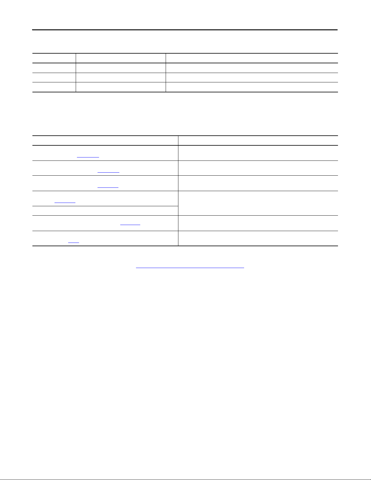
These documents contain additional information concerning related products
from Rockwell Automation.
Resource Description
Kinetix 6200 and Kinetix 6500 Modular Multi-axis Servo Drive
User Manual, publication 2094-UM002
Kinetix 6200 and Kinetix 6500 Safe Speed Monitoring
Safety Reference Manual, publication 2094-RM001
Kinetix Safe-off Feature
Safety Reference Manual, publication GMC-RM002
System Design for Control of Electrical Noise Reference Manual,
publication GMC-RM001
EMC Noise Management DVD, publication GMC-SP004
Kinetix Motion Control Selection Guide, publication GMC-SG001
Safety Guidelines for the Ap plication, Installation and Maintenance of Solid State
Control, publication
SGI-1.1
Information on installing, configuring, startup, troubleshooting, and applications for your
Kinetix 6200 and Kinetix 6500 servo drive system.
Information on wiring, troubleshooting, and configuring your Kinetix 6200 and Kinetix6500
servo drives with the safe speed-monitoring functionality.
Information on wiring and troubleshooting your Kinetix 6000 servo drives with the safe-off
feature.
Information, examples, and techniques designed to minimize system failures caused by
electrical noise.
Specifications, motor/servo- drive system combinations, and accessories for Kinetix motion
control products.
Describes important differences between solid state control and hardwired electromechanical
devices.
You can view or download publications at:
http://www.rockwellautomation.com/literature
documentation, contact your local Allen-Bradley® distributor or Rockwell
Automation sales representative.
. To order paper copies of technical
8 Rockwell Automation Publication 2094-RM002B-EN-P - May 2012

Safety Concept
Chapter 1
Introduction
Safety Certification
This chapter describes the safety performance level concept and how the
Kinetix 6200 and Kinetix 6500 drives can meet the requirements for SIL CL3,
CAT 4, or PLe applications.
Top ic Pag e
Safety Certification 9
PFD and PFH Definitions 11
PFD and PFH Data 11
Safe State 12
Safety Reaction Time 12
Contact Information If Failure Occurs 12
Automatic Drive Replacement (ADR) 12
The Kinetix 6200 and Kinetix 6500 drives are certified for use in safety
applications up to and including SIL CL3 according to EN 61800-5-2,
EN 61508, and EN 62061, Performance Level PLe and CAT 4 according to
ISO 13849-1. Safety requirements are based on the standards current at the time
of certification.
The TÜV Rheinland group has approved the Kinetix 6200 and Kinetix 6500
drives for use in safety-related applications where the de-energized state is
considered to be the safe state. All of the examples related to I/O included in this
manual are based on achieving de-energization as the safe state for typical
Machine Safety and Emergency Shutdown (ESD) systems.
Rockwell Automation Publication 2094-RM002B-EN-P - May 2012 9
Chapter 1 Safety Concept
IMPORTANT
Important Safety Considerations
You are responsible for the following:
• The set-up, safety rating, and validation of any sensors or actuators
connected to the system
• Completing a system-level risk assessment and reassessing the system any
time a change is made
• Certification of the system to the desired safety performance level
• Project management and proof testing
• Access control to the system, including password handling
When applying functional safety, restrict access to qualified, authorized
personnel who are trained and experienced.
ATTENTION: When designing your system, consider how personnel will exit
the machine if the door locks while they are in the machine. Additional
safeguarding devices may be required for your specific application.
Safety Category 4 Performance Definition
The safety-related parts have to be designed with the following considerations to
achieve Safety Category 4 according to ISO 13849-1:2006:
• The safety-related parts of machine control systems and/or their protective
equipment, as well as their components, must be designed, constructed,
selected, assembled, and combined in accordance with relevant standards
so that they can withstand expected conditions.
• Basic safety principles must be applied.
• A single fault in any of its parts does not lead to a loss of safety function.
• A single fault is detected at or before the next demand of the safety
function, or, if this detection is not possible, then an accumulation of faults
must not lead to a loss of the safety function.
• The average diagnostic coverage of the safety-related parts of the control
system must be high, including the accumulation of faults.
• The mean time to dangerous failure of each of the redundant channels
must be high.
• Measures against common cause failure must be applied.
Stop Category 0 Definition
Stop Category 0 is achieved with immediate removal of power to the actuator,
resulting in an uncontrolled coast to stop. Safe Torque Off accomplishes a Stop
Category 0 stop.
10 Rockwell Automation Publication 2094-RM002B-EN-P - May 2012
Safety Concept Chapter 1
Performance Level and Safety Integrity Level (SIL) CL3
For safety-related control systems, Performance Level (PL), according to ISO
13849-1, and SIL levels, according to EN 61508 and EN 62061, include a rating
of the system’s ability to perform its safety functions. All of the safety-related
components of the control system must be included in both a risk assessment and
the determination of the achieved levels.
Refer to the ISO 13849-1, EN 61508, and EN 62061 standards for complete
information on requirements for PL and SIL determination.
PFD and PFH Definitions
PFD and PFH Data
Safety-related systems can be classified as operating in either a Low Demand
mode, or in a High Demand/Continuous mode:
• Low Demand mode: where the frequency of demands for operation made
on a safety-related system is no greater than one per year or no greater than
twice the proof-test frequency.
• High Demand/Continuous mode: where the frequency of demands for
operation made on a safety-related system is greater than once per year or
greater than twice the proof test interval.
The SIL value for a low demand safety-related system is directly related to orderof-magnitude ranges of its average probability of failure to satisfactorily perform
its safety function on demand or, simply, average probability of failure on demand
(PFD). The SIL value for a High Demand/Continuous mode safety-related
system is directly related to the probability of a dangerous failure occurring per
hour (PFH).
These PFD and PFH calculations are based on the equations from Part 6 of
EN 61508 and show worst-case values.
This table provides data for a 20-year proof test interval and demonstrates the
worst-case effect of various configuration changes on the data.
Table 2 - PFD and PFH for 20-year Proof Test Interval
Attribute Value
PFH [1e-9] 4.09
PFD [1e-4] 3.90
SFF % 99.5
Rockwell Automation Publication 2094-RM002B-EN-P - May 2012 11

Chapter 1 Safety Concept
IMPORTANT
Safe State
Safety Reaction Time
The Safe State encompasses all operation that occurs outside of the other
monitoring and stopping behavior defined as part of the drive. While the drive is
in the Safe State, all safety control outputs are in their safe state (de-energized).
When you cycle power, the drive enters the Safe State for self-testing. If the selftests pass, the drive remains in the Safe State until a successful safe stop reset
occurs.
If a Safe State fault is detected, the drive goes to the Safe State. This includes
faults related to integrity of hardware or firmware.
For more information on faults, refer to Chapter 5
The safety reaction time is the amount of time from a safety-related event as
input to the system until the system is in the Safe State.
The safety reaction time from an input signal condition that triggers a safe stop,
to the initiation of the Safe Stop Type, is 12 ms, max.
For cascaded systems, the reaction time is multiplied by the number of drives
in the drive system. For example, drive systems with three cascaded drives
(first, middle, and last), have a reaction time of 36 ms, max.
.
Contact Information If Failure Occurs
Automatic Drive Replacement (ADR)
If you experience a failure with any safety-certified device, contact your local
Rockwell Automation distributor. With this contact, you can do the following:
• Return the device to Rockwell Automation so the failure is appropriately
logged for the catalog number affected and a record is made of the failure.
• Request a failure analysis (if necessary) to determine the probable cause of
the failure.
You can replace IAM and AM power modules, and the associated control
modules, at any time without any need for configuration or program changes.
12 Rockwell Automation Publication 2094-RM002B-EN-P - May 2012
Installation and Wiring
Chapter 2
Introduction
General Safety Information
This chapter provides details on connecting devices and wiring the
2090-K6CK-D44M and 2090-K6CK-D44S0 low-profile connector kits.
Top ic Pag e
General Safety Information 13
Power Supply Require ments 14
Wiring the Safety Connections 14
Terminal Connections 18
ATTENTION: The drive is intended to be part of the safety-related control
system of a machine. Before installation, a risk assessment should be
performed to determine whether the specifications of this safety option are
suitable for all foreseeable operational and environmental characteristics for
the system to which it is to be installed.
Observe all electrical safety regulations stipulated by the appropriate technical
authorities.
ATTENTION: Make sure that the electrical power supplied to the drive is
switched off before making connections.
Refer to the Kinetix 6200 and Kinetix 6500 Modular Multi-axis Servo Drive
User Manual, publication 2094-UM002
Rockwell Automation Publication 2094-RM002B-EN-P - May 2012 13
, for more information.
Loading...