


 Loading...
Rockwell Automation 2706-P42, 2706-P43, 2706-P44, 2706-P72, 2706-P74 User Manual
...
InView Marquee
Message Display
2706-P22R, 2706-P42, 2706-P43,
2706-P44, 2706-P72, 2706-P74,
2706-P92, 2706-P94
User Manual

Important User Information Solid state equipment has operational characteristics differing from those of electromechanical equipment. Safety Guidelines for the Application,
Installation and Maintenance of Solid State Controls (publication SGI-1.1 available from your local Rockwell Automation sales office or online at http://literature.rockwellautomation.com) describes some important differences between solid state equipment and hard-wired electromechanical devices. Because of this difference, and also because of the wide variety of uses for solid state equipment, all persons responsible for applying this equipment must satisfy themselves that each intended application of this equipment is acceptable.
In no event will Rockwell Automation, Inc. be responsible or liable for indirect or consequential damages resulting from the use or application of this equipment.
The examples and diagrams in this manual are included solely for illustrative purposes. Because of the many variables and requirements associated with any particular installation, Rockwell Automation, Inc. cannot assume responsibility or liability for actual use based on the examples and diagrams.
No patent liability is assumed by Rockwell Automation, Inc. with respect to use of information, circuits, equipment, or software described in this manual.
Reproduction of the contents of this manual, in whole or in part, without written permission of Rockwell Automation, Inc., is prohibited.
Throughout this manual, when necessary, we use notes to make you aware of safety considerations.
|
|
|
|
|
|
|
Identifies information about practices or circumstances that can cause |
|
WARNING |
||||||||
|
an explosion in a hazardous environment, which may lead to personal |
|||||||
|
|
|
|
|
|
|
||
|
|
|
|
|
|
|
injury or death, property damage, or economic loss. |
|
|
|
|
|
|
|
|
|
|
|
|
|
|
|
|
|
|
|
|
|
|
|
|
|
|
|
|
|
|
|
|
|
|
|
Identifies information that is critical for successful application and |
|
IMPORTANT |
|
|||||||
|
understanding of the product. |
|||||||
|
|
|
|
|
|
|
||
|
|
|
|
|
|
|
|
|
|
|
|
|
|
|
|
Identifies information about practices or circumstances that can lead |
|
ATTENTION |
|
|||||||
|
to personal injury or death, property damage, or economic loss. |
|||||||
|
|
|
|
|
|
|
||
|
|
|
|
|
|
|
Attentions help you identify a hazard, avoid a hazard, and recognize |
|
|
|
|
|
|
|
|
the consequence |
|
|
|
|
|
|
|
|
||
|
|
|
|
|
|
|
||
|
|
|
|
|
|
|
||
|
|
|
|
|
|
|
Labels may be located on or inside the equipment, for example, a drive |
|
SHOCK HAZARD |
|
|||||||
|
|
|
|
|
|
|
or motor, to alert people that dangerous voltage may be present. |
|
|
|
|
|
|
||||
|
|
|
|
|
|
|
||
|
|
|
||||||
|
|
|
|
|
|
|
Labels may be located on or inside the equipment, for example, a drive |
|
BURN HAZARD |
|
|||||||
|
|
|
|
|
|
|
or motor, to alert people that surfaces may be dangerous |
|
|
|
|
|
|
|
|
||
|
|
|
|
|
|
|
temperatures. |
|
|
|
|
|
|
|
|
|
|
|
|
|
|
|
|
|
|
|

Summary of Changes
This document describes the InView Marquee Message Display.
Revision bars in the margin identify updated information. Changes for this version of the document include:
Change |
Page |
Updated information on how to change the serial address |
1-2 |
|
|
Added information about how to use the 2706-PCABLE1 to |
1-27 |
download a message application |
|
|
|
Added information about the communication module when |
2-11 |
you set the IP address. |
|
|
|
Publication 2706-UM016D-EN-P - March 2006

2 Summary of Changes
Publication 2706-UM016D-EN-P - March 2006

Table of Contents
Install InView Marquee Message
Display
InView System Connectivity
Chapter 1
Introduction . . . . . . . . . . . . . . . . . . . . . . . . . . . . . . . . . . . 1-1 Wire and Safety Guidelines . . . . . . . . . . . . . . . . . . . . . . . . 1-1 Change the Serial Address . . . . . . . . . . . . . . . . . . . . . . . . . 1-2 Checkout Procedure . . . . . . . . . . . . . . . . . . . . . . . . . . . . . 1-2 Electrical Connections for 2706-P42, 2706-P43 and
2706-P44 Displays . . . . . . . . . . . . . . . . . . . . . . . . . . . . . . . 1-2 Mount the 2706-P42, 2706-P43 and 2706-P44 Displays . . . . 1-6 Wall Mount . . . . . . . . . . . . . . . . . . . . . . . . . . . . . . . . . 1-7 Ceiling Mount . . . . . . . . . . . . . . . . . . . . . . . . . . . . . . . 1-9 Stack Mount . . . . . . . . . . . . . . . . . . . . . . . . . . . . . . . . 1-10 Back-to-back Mount. . . . . . . . . . . . . . . . . . . . . . . . . . . 1-11
Mount the 2706-P72 and 2706-P74 series NEMA 4
and 4x models . . . . . . . . . . . . . . . . . . . . . . . . . . . . . . . . . 1-13 Electrical Connections for 2706-P72 and 2706-P74 Signs . . . 1-14 Mount the 2706-P92C and 2706-P94C Sign . . . . . . . . . . . . . 1-17 Back-to-back Mount. . . . . . . . . . . . . . . . . . . . . . . . . . . 1-19 Electrical Connections for 2706-P92C and 2706-P94C Signs . 1-19 Mount the 2706-P22R Display . . . . . . . . . . . . . . . . . . . . . . 1-23 Panel Cutout Dimensions for 2706-P22R Display . . . . . . 1-23 Dimensions for 2706-P22R Display . . . . . . . . . . . . . . . . 1-24 Electrical Connections for 2706-P22R Display . . . . . . . . . . . 1-24 Communication Connections for 2706-P22R Display . . . . . . 1-25 DIP Switch Settings for 2706-P22R Display . . . . . . . . . . . . . 1-26 Download a Message Application . . . . . . . . . . . . . . . . . . . 1-27 RS-232 to RS-485 Networking. . . . . . . . . . . . . . . . . . . . . . . 1-27 RS-485 Echo . . . . . . . . . . . . . . . . . . . . . . . . . . . . . . . . . . . 1-28 Global Addressing . . . . . . . . . . . . . . . . . . . . . . . . . . . . 1-29 Ground and Terminate the RS-485 Network . . . . . . . . . . . . 1-29
Chapter 2
Serial ASCII Communications. . . . . . . . . . . . . . . . . . . . . . . 2-1 Features . . . . . . . . . . . . . . . . . . . . . . . . . . . . . . . . . . . . . . 2-1
2706-P42, 2706-P43, 2706-P44, 2706-P72, and 2706-P74 Displays . . . . . . . . . . . . . . . . . . . . . . . . . . . . . . . . . . . 2-1 2706-P22 Display . . . . . . . . . . . . . . . . . . . . . . . . . . . . . 2-2
Dip Switch Information for the 2706-P9x . . . . . . . . . . . . . . 2-4 Switch 1 . . . . . . . . . . . . . . . . . . . . . . . . . . . . . . . . . . . 2-4 Switch 2 . . . . . . . . . . . . . . . . . . . . . . . . . . . . . . . . . . . 2-5 Additional Information for 2706-P9x Displays . . . . . . . . 2-6
Power-up Messages. . . . . . . . . . . . . . . . . . . . . . . . . . . . . . 2-10
2706-P42, 2706-P43, 2706-P44, 2706-P72, 2706-P74, 2706-P92, and 2706-P94 Displays . . . . . . . . . . . . . . . . . 2-10 2706-P22: Display . . . . . . . . . . . . . . . . . . . . . . . . . . . . 2-10
Display Setup . . . . . . . . . . . . . . . . . . . . . . . . . . . . . . . . . . 2-11 Set the IP Address . . . . . . . . . . . . . . . . . . . . . . . . . . . . . . . 2-11
Publication 2706-UM016D-EN-P - March 2006

ii Table of Contents
|
Gateway Address and Subnet Mask Setup . . . . . . . . . . . |
2-15 |
|
Create the Message File . . . . . . . . . . . . . . . . . . . . . . . . . . . |
2-16 |
|
Attach a Note to a Message . . . . . . . . . . . . . . . . . . . . . |
2-17 |
|
Text Color . . . . . . . . . . . . . . . . . . . . . . . . . . . . . . . . . . |
2-17 |
|
Date, Time and Variables . . . . . . . . . . . . . . . . . . . . . . . |
2-17 |
|
Category . . . . . . . . . . . . . . . . . . . . . . . . . . . . . . . . . . . |
2-18 |
|
Message Priorities . . . . . . . . . . . . . . . . . . . . . . . . . . . . |
2-18 |
|
Pause . . . . . . . . . . . . . . . . . . . . . . . . . . . . . . . . . . . . . |
2-19 |
|
Message Header. . . . . . . . . . . . . . . . . . . . . . . . . . . . . . |
2-19 |
|
Preview Messages . . . . . . . . . . . . . . . . . . . . . . . . . . . . |
2-19 |
|
Set the Display Address . . . . . . . . . . . . . . . . . . . . . . . . |
2-19 |
|
Download Messages . . . . . . . . . . . . . . . . . . . . . . . . . . |
2-20 |
|
Clear Memory/Message Queue . . . . . . . . . . . . . . . . . . |
2-22 |
|
Chapter 3 |
|
Serial ASCII Communications |
Use a PLC5 out Channel Zero . . . . . . . . . . . . . . . . . . . . . . |
3-1 |
|
Use an SLC 5/03, 5/04, or 5/05 out Channel Zero . . . . . . . . |
3-2 |
|
Use a MicroLogix out Channel Zero or One . . . . . . . . . . . . |
3-3 |
|
Use ControlLogix Processor out Channel Zero . . . . . . . . . . |
3-4 |
|
Use the CompactLogix Processor out Channel Zero or One |
3-5 |
|
Use FlexLogix Processor out Channel Zero. . . . . . . . . . . . . |
3-6 |
|
Chapter 4 |
|
InView Protocol |
Introduction . . . . . . . . . . . . . . . . . . . . . . . . . . . . . . . . . . . |
4-1 |
|
Trigger Messages and Update Variables . . . . . . . . . . . . . . . |
4-1 |
|
The CTRL-T Function Frame. . . . . . . . . . . . . . . . . . . . . |
4-1 |
|
The CTRL-V Function Frame - Numeric Variables . . . . . |
4-3 |
|
The CTRL-V Function Frame - Alphanumeric Variables . |
4-4 |
|
Examples of the Control-T Function. . . . . . . . . . . . . . . . . . |
4-5 |
|
Trigger a Message on all Displays using |
|
|
Priority Messaging . . . . . . . . . . . . . . . . . . . . . . . . . . . . |
4-5 |
|
Trigger a Message on a Specific Display using Priority |
|
|
Messaging . . . . . . . . . . . . . . . . . . . . . . . . . . . . . . . . . . |
4-6 |
|
Add a Message on all Displays . . . . . . . . . . . . . . . . . . . |
4-7 |
|
Adding a Message on a Specific Display . . . . . . . . . . . . |
4-7 |
|
Remove all Messages on all Displays . . . . . . . . . . . . . . |
4-7 |
|
Remove all Messages on a Specific Display . . . . . . . . . . |
4-8 |
|
Remove a Message on a Specific Display . . . . . . . . . . . |
4-9 |
|
Examples of the Control-V Function. . . . . . . . . . . . . . . . . . |
4-9 |
|
Update a Variable on all Displays . . . . . . . . . . . . . . . . . |
4-9 |
|
Update Variable on a Specific Display . . . . . . . . . . . . . |
4-10 |
|
Modbus ASCII Protocol to Download and |
|
|
Preview Messages . . . . . . . . . . . . . . . . . . . . . . . . . . . . . . . |
4-10 |
|
How InView Sign Communication Protocol is used |
|
|
with Modbus ASCII Protocol . . . . . . . . . . . . . . . . . . . . . . . |
4-11 |
Publication 2706-UM016D-EN-P - March 2006

Table of Contents |
iii |
|
|
Mode of Transmission . . . . . . . . . . . . . . . . . . . . . . . . . 4-12 InView Display Memory Map . . . . . . . . . . . . . . . . . . . . 4-12 Methods of Transmission . . . . . . . . . . . . . . . . . . . . . . . 4-13 Message Format . . . . . . . . . . . . . . . . . . . . . . . . . . . . . . 4-14 Longitudinal Redundancy Check (LRC) Error
Detection and Calculation . . . . . . . . . . . . . . . . . . . . . . 4-16 Examples of Modbus ASCII Functions . . . . . . . . . . . . . . . . 4-17 Heartbeat Function . . . . . . . . . . . . . . . . . . . . . . . . . . . 4-18 Clear the Display Memory . . . . . . . . . . . . . . . . . . . . . . 4-20
Clear the Message Queue using Modbus ASCII
in Broadcast Mode (Recommended) . . . . . . . . . . . . . . . 4-20 Clear the Message Queue using Modbus ASCII in Guaranteed Mode . . . . . . . . . . . . . . . . . . . . . . . . . . . . 4-21 Set Time in Broadcast Mode with AM/PM Format . . . . . 4-21 Set Time in Broadcast Mode with 24 Hour Format. . . . . 4-22 Set Day and Date in Broadcast Mode . . . . . . . . . . . . . . 4-23 Preview a Message. . . . . . . . . . . . . . . . . . . . . . . . . . . . 4-25 Download Messages . . . . . . . . . . . . . . . . . . . . . . . . . . 4-27 Add/Remove a Message using a Modbus ASCII 10
Frame Query (Recommended) . . . . . . . . . . . . . . . . . . . 4-33 Add/Remove a Message using Modbus ASCII 10
Frame Transmission . . . . . . . . . . . . . . . . . . . . . . . . . . . 4-33 Priority Messaging using a Modbus ASCII Query (Recommended) . . . . . . . . . . . . . . . . . . . . . . . . . . . . . 4-34 Priority Messaging using a Modbus ASCII Transmission . 4-35 Update a Variable using a Modbus ASCII 06 Frame in Broadcast Mode (Recommended) . . . . . . . . . . . . . . . . . 4-35 Update a Variable using a Modbus ASCII 06 Frame in Guaranteed Mode . . . . . . . . . . . . . . . . . . . . . . . . . . . . 4-36 Update Variables using a Modbus ASCII 10 frame
in Broadcast mode (Recommended) . . . . . . . . . . . . . . . 4-36 Update Variables using a Modbus ASCII 10 frame in Guaranteed mode . . . . . . . . . . . . . . . . . . . . . . . . . . . . 4-37 Read the Message Queue using a Modbus ASCII 03
frame . . . . . . . . . . . . . . . . . . . . . . . . . . . . . . . . . . . . . 4-38 Read Variables in a Display using a Modbus ASCII 03
frame . . . . . . . . . . . . . . . . . . . . . . . . . . . . . . . . . . . . . 4-39 Change the InView Display Address . . . . . . . . . . . . . . . 4-40
InView Display Communication Protocol Functions and Descriptions . . . . . . . . . . . . . . . . . . . . . . . . . . . . . . . . . . . 4-41
InView Message Format used within Modbus ASCII
Protocol . . . . . . . . . . . . . . . . . . . . . . . . . . . . . . . . . . . 4-41 Special Function Command . . . . . . . . . . . . . . . . . . . . . 4-45 Text Position Placement . . . . . . . . . . . . . . . . . . . . . . . . 4-51 ASCII Characters . . . . . . . . . . . . . . . . . . . . . . . . . . . . . . . . 4-52 Reference Material. . . . . . . . . . . . . . . . . . . . . . . . . . . . . . . 4-52
Publication 2706-UM016D-EN-P - March 2006

iv |
Table of Contents |
|
|
InView Control and
InView Control API
Specifications
Catalog Number Explanation
Temperature Protection in
NEMA-Rated Enclosures
Chapter 5
Introduction . . . . . . . . . . . . . . . . . . . . . . . . . . . . . . . . . . . 5-1
Quick Overview . . . . . . . . . . . . . . . . . . . . . . . . . . . . . . . . 5-1
Reference . . . . . . . . . . . . . . . . . . . . . . . . . . . . . . . . . . . . . 5-2
Properties . . . . . . . . . . . . . . . . . . . . . . . . . . . . . . . . . . . . . 5-3
Methods . . . . . . . . . . . . . . . . . . . . . . . . . . . . . . . . . . . . . . 5-7
Appendix A
2706-P43, 2706-P42, 2706-P44, 2706-P72 Specifications . . . . A-1
2706-P92, 2706-P94 Specifications . . . . . . . . . . . . . . . . . . . A-2
2706-P22R Specifications . . . . . . . . . . . . . . . . . . . . . . . . . . A-3
Appendix B
Appendix C
Index
Publication 2706-UM016D-EN-P - March 2006

Chapter 1
Install InView Marquee Message Display
Introduction
These instructions show how to change the serial address and how to mount InView series signs with NEMA Types 4, 4X, and 12 enclosures. These signs are intended for indoor use only. Type 4 enclosures are intended to provide a degree of protection against windblown dust and rain, splashing water, and hose-directed water. Type 4X enclosures are intended to provide a degree of protection against corrosion, windblown dust and rain, splashing water, and hose-directed water. Type 12 enclosures are in a sealed case that is, dust free, gasketing, and spray down resistant.
Wire and Safety Guidelines Install the InView display conforming to NFPA 70E, Electrical Safety Requirements for Employee Workplaces. In addition to the NFPA
general guidelines, refer to the following.
•Careful cable routing helps minimize electrical noise. Route incoming power to the module by a separate path from the communication cables.
TIP |
Do not run communications wiring and power |
|
wiring in the same conduit! |
||
|
•Where communication and wire paths must cross, make their intersection perpendicular.
•Grounding helps limit the effects of noise due to electromagnetic interference (EMI). To avoid problems caused by EMI, properly ground all equipment and use shielded cables.
EXPLOSION HAZARD
WARNING
Do not connect or disconnect equipment unless power has been switched off and area is known to be non-hazardous.
Publication 2706-UM016D-EN-P - March 2006

1-2 Install InView Marquee Message Display
IMPORTANT |
Power wiring must be in accordance with Class I, |
|
Class II and Class III Division 2 wiring methods |
||
|
||
|
||
|
(Articles 501-4(b), 502-4(b) and 503-3(b) of the |
|
|
National Electrical Code, NFPA70) and in |
|
|
accordance with the local authority having |
|
|
jurisdiction. |
|
|
|
Change the Serial Address
Checkout Procedure
A serial address for an InView sign is a number from 1 to 254 in hexadecimal (01 to FE). All signs leave the factory with a default address of 1 or 01.
This serial address is resident in the InView display and is used for RS485 networking. If one of the factory network communications modules are used (2706-Pxxxx), this serial address is typically left at its factory default and the network node or IP address is set in the factory network communication module.
After you install a sign according to the Electrical and Mounting Instructions, make sure the sign is installed properly by applying power to it. The following information should be displayed on the sign.
•Firmware part number and version letter (xxxx).
•Amount of RAM in the sign, (256K).
•Serial address of the sign (a number from 01 to FE or from 1 to 254).
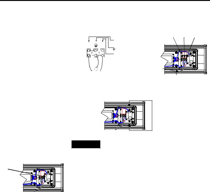
Electrical Connections for 2706-P42, 2706-P43 and 2706-P44 Displays
Hazardous voltage. Contact with high voltage may
WARNING
cause death or serious injury. Always disconnect power to sign prior to servicing.
To connect the 2706-P42, 2706-P43, and 2706-P44 displays:
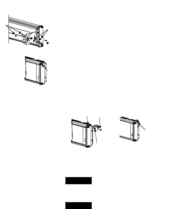
1.Remove the power supply cover by unscrewing its 6 screws. Save the screws for a later step.
Publication 2706-UM016D-EN-P - March 2006
Install InView Marquee Message Display |
1-3 |
|
|
|
Hole plugs, |
|
top, removed |
Hole plugs, |
Wing nuts for |
bottom, removed |
hole plugs |
TIP |
It is recommended that you install power and |
|
serial wires at the bottom of the power supply |
||
|
||
|
||
|
enclosure to reduce noise from power wires |
|
|
crossing serial wires. |
You can install the power or serial wires at the top of the enclosure if necessary.
2.Remove the left or right conduit hole plug from the top of the enclosure by removing its wing nut inside the enclosure.
Save the hole plug for a later step.
3.Insert the power wires through the left conduit hole on either the top or the bottom of the sign.
TIP |
Use watertight conduit connectors only. |
|
Flexible conduit should be used. |
||
|
||
|
Internal serial wires
|
Insert the |
|
|
power wires |
|
|
into one of |
|
Internal wiring for |
these |
|
conduits. |
||
power supply |
||
|
4.Strip the wires back 6.35 mm (1/4 in.). Connect the incoming electrical wires.
TIP |
Be sure to place the wires so they are not caught by |
|
screws when replacing the power supply cover, and |
||
|
||
|
||
|
also so they do not interfere with fan operation. |
Publication 2706-UM016D-EN-P - March 2006
1-4 Install InView Marquee Message Display
Line |
Ground |
|
|
GREEN |
Neutral |
||
(Hot) |
|||
w/ |
(Line 2): |
||
BLACK |
|||
Yellow |
WHITE |
||
|
Hot (Line 1)
H N
Ground
Neutral (Line 2)
100 to 240V ac @ 50/60 Hz
5.Insert the serial wires through the right conduit hole on either the top or the bottom of the sign.
Insert the serial wires
 into one of these conduit holes.
TIP |
TB1 can be used for incoming serial connection for |
|
RS-232 or RS-485. |
||
|
||
TB1 - Full |
|
|
TB1 |
|
Pin |
Pin Name |
Pin |
|
Pin Name |
|
|
|
|
|
|
|
1. |
GND |
|
|
5. |
RS-485(+) |
|
|
|
|
|
|
2. |
+5V |
|
|
6. |
RS-485(-) |
|
|
|
|
|
|
3. |
RS-232 |
TX |
|
7. |
NC |
|
|
|
|
|
|
4. |
RS-232 |
RX |
|
8. |
SHIELD |
|
|
|
|
|
|
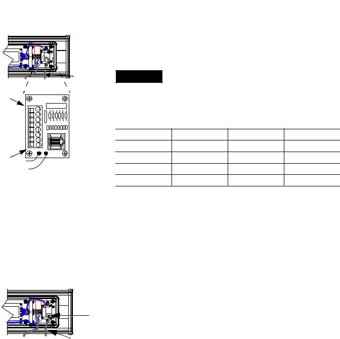
6. Connect the incoming serial wires.
Publication 2706-UM016D-EN-P - March 2006
Install InView Marquee Message Display |
1-5 |
|
|
TB1 can be used for incoming RS-232 or RS-485 serial connection. They cannot be connected at the same time. RS-485
is recommended to reduce undesirable electrical interference.

 TB1
TB1
Incoming serial |
TIP |
Be sure to place the wires so they are not caught by |
|
wires |
|||
screws when replacing the power supply cover, and |
|||
|
|
||
|
|
also so they do not interfere with fan operation. |
8 |
|
|
|
|
7 |
|
|
|
|
6 |
TB1 - RS-232 |
|
|
|
5 |
|
|
|
|
|
|
|
|
|
4 |
Pin |
Pin Name |
Pin |
Pin Name |
3 |
1. |
GND |
5. |
NC |
2 |
||||
1 |
2. |
NC |
6. |
NC |
|
||||
|
3. |
RS-232 TX |
7. |
NC |
|
4. |
RS-232 RX |
8. |
NC |
P1
Incoming  serial wires
TB1 - RS-485
Pin |
Pin Name |
Pin |
|
Pin Name |
|
|
|
|
|
1. |
NC |
|
5. |
RS-485(+) |
|
|
|
|
|
2. |
NC |
|
6. |
RS-485(-) |
|
|
|
|
|
3. |
NC |
|
7. |
NC |
|
|
|
|
|
4. |
NC |
|
8. |
SHIELD |
|
|
|
|
|
7.P1 can be used for incoming RS-232 only, although it is optional and not recommended.
P1 is intended for RS-232 application downloads and RS-485 terminating resistor connection.
See publication 2706-IN007 for more information on RS-485 termination.
TIP |
Be sure to place the wires so they are not caught by |
|
screws when replacing the power supply cover, and |
||
|
||
|
||
|
also so they do not interfere with fan operation. |
8.To maintain NEMA compliance and to prevent EMI emissions, install hole plugs in any open conduit holes in the power supply enclosure.
Publication 2706-UM016D-EN-P - March 2006

1-6 Install InView Marquee Message Display
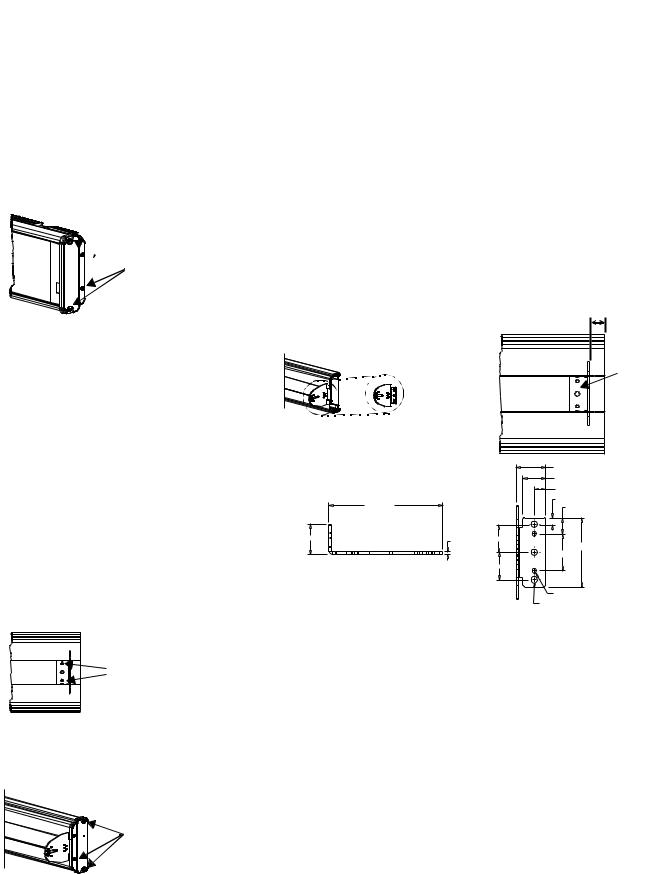
Mount the 2706-P42, 2706-P43 and 2706-P44 Displays
If needed, there is an extra hole plug supplied in addition to any hole plugs removed in Step 2 on page 3.
9.Replace the power supply cover using the 6 screws from when the cover was removed.
10.Torque the screws to 2.7 Nm (24 lb-in).
11.Connect the power cable to a power source.
TIP |
Only qualified personnel should install the InView |
|
signs. |
||
|
||
|
||
|
InView signs are for indoor use only and should not |
|
|
be continuously exposed to direct sunlight. |
|
|
Mounting hardware that is used to hang or suspend |
|
|
signs must be capable of supporting at least 4 times |
|
|
the total weight of any/all signs mounted together. |
|
|
For integrity of the case, do not drill holes in or |
|
|
modify the case. |
Disconnect power before you mount a sign.
Hazardous voltage. Contact with high voltage may
WARNING
cause death or serious injury. Always disconnect power to sign prior to servicing.
Publication 2706-UM016D-EN-P - March 2006
Install InView Marquee Message Display |
1-7 |
|
|
 Remove
these screws.
Wall Mount
TIP |
Remove only one end cap at a time. |
|
|
|
|
To mount the display to a wall:
1.Remove the 4 screws and the end cap from one end of the sign.
2.Slide one of the wall mounting brackets onto the back of the sign until it is approximately 13 mm (0.5 in.) away from the end of the sign.
|
0.5” |
|
Wall mounting |
Wall |
|
bracket |
||
mounting |
||
|
||
|
bracket |
|
33.13 (1.30) |
|
25.40 (1.00) |
|
12.70 (0.50) |
|
7.62 (0.30) |
127 (5.00) |
17.65 (0.70) |
33.13 (1.305) |
2.65 (0.105) |
30.35 (1.195) |
|
|
75.95 (2.99) |
|
|
40.64 (1.60) |
|
|
30.35 (1.195) |
Dimensions are in mm (inches). |
|
4.04 (0.159) 1032 UNC-2B 2 Holes |
|
|
7.11 (0.280) Thru 3 Holes |
Phillips screws go here.
Fasten

 these screws.
3.Use two 10-32 x 1/4 Phillips screws (supplied) to secure the wall mounting bracket to the back of the sign.
4.Torque the screws to 2.7 Nm (24 lb-in).
5.Replace the end cap using the 4 screws removed in Step 1 above.
6.Torque the screws to 2.7 Nm (24 lb-in).
7.Repeat Steps 1 to 6 for the other end of the sign.
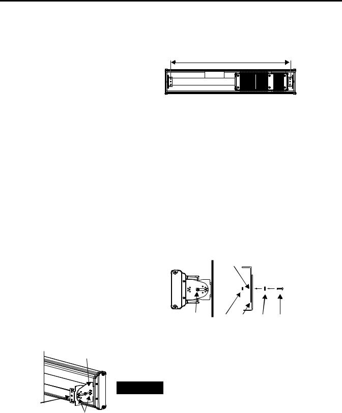
Approximate distances between the bracket holes, center-to-center, are shown below.
Publication 2706-UM016D-EN-P - March 2006
1-8 Install InView Marquee Message Display
94 cm (37 in.) for 2706-P42
183 cm (72.2 in.) for 2706-P43
185.4 cm (73 in.) for 2706-P44
Mounting bracket on the sign
8.Attach the two remaining wall mounting brackets to a wall so that they align with the brackets on the sign.
TIP |
Do not install the sign directly to drywall or |
|
plaster-board. The sign must be fastened to a wall |
||
|
||
|
||
|
capable of supporting at least four times the weight |
|
|
of the sign. |
9.Connect the mounting brackets on each end of the sign together using a 5/16 Phillips screw and a 5/16 washer through the mounting holes, as shown below, securing with a 5/16 nut.
Do not tighten the nut at this time.
Side view |
Top view |
|
Mounting |
|
holes |
Screw and |
Nut Brackets Washer Screw |
washer through |
|
mounting holes |
|
10.Match the alignment holes of the brackets on the sign with the alignment holes of the brackets on the wall so that the sign is at the desired viewing angle.
|
TIP |
The second mounting bracket is shown here for |
|
illustration only. It is actually mounted to the wall. |
|
|
|
|
Mounting |
|
|
bracket on the |
11. Fasten the mounting brackets together using two 10-32 x 3/4 |
|
Alignment holes |
||
wall
Phillips screws, two 10-32 washers, and two 10-32 lock nuts through selected alignment holes on each end of the sign.
12. Torque to 2.7 Nm (24 lb-in).
Publication 2706-UM016D-EN-P - March 2006
Install InView Marquee Message Display |
1-9 |
|
|
|
13. Torque the 5/16 nuts in the mounting holes (See Step 9) to |
Lock |
2.7 Nm (24 lb-in). |
nuts |
|
|
Washers |
Ceiling Mount
Phillips
 screws
To mount the display to the ceiling:
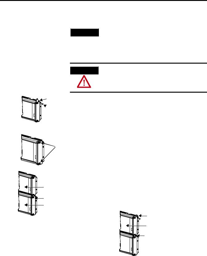
1. Remove one screw from the top of the end cap.
Remove  this screw.
2.Line up a ceiling bracket with the top hole on the sign’s end cap so the bracket fits in the indentation.
There are left and right ceiling brackets. Use the one that fits with the screw hole’s countersunk side facing out.
3.Secure the ceiling bracket with the screw removed in Step 1 and torque the screw to 2.7 Nm (24 in-lb).
Screw hole Screw
Ceiling
 bracket mounted to
end cap.
Ceiling bracket
4.Repeat steps 1 through 3 for the other end of the sign.
5.Use chains (not supplied) to hang the sign from a ceiling.
TIP
TIP
Use chains capable of supporting 4 times the total weight of the sign(s).
The hole you select in the ceiling bracket for the chain determines the angle at which the sign hangs.
Publication 2706-UM016D-EN-P - March 2006
1-10 Install InView Marquee Message Display
Stacking bracket
 Screw
Screw
Stack Mount
TIP
Up to 4 signs can be hung together vertically (‘stacked’). Mounting system for stack mounting must support a minimum of four times the total weight of all signs being stacked.
Possible crush hazard. Do not stack more than 4
WARNING
signs. Otherwise signs may fall causing serious injury or death.
To stack the signs:
1. Remove the top screw from each end cap of the bottom sign
Remove  these
these
screws.
Next sign
Stacking bracket
Bottom sign
2.Use the screw removed in Step 1 to fasten a stacking bracket to each end cap, countersunk side out, and torque to 2.7 Nm
(24 lb-in).
3.Remove the top and bottom screws from each end of the remaining signs.
4.For each end of the signs, secure the stacking bracket from the bottom sign to the next sign using one of the screws removed in Step 3 and torque to 2.7 Nm (24 lb-in).
5.Secure a ceiling bracket to the top of each end cap on the top sign.
See Step 2 of the Ceiling Mount instructions on page 1-9.
Ceiling bracket Top sign
Stacking bracket
6. Use a chain (not supplied) to hang the signs from the ceiling.
Publication 2706-UM016D-EN-P - March 2006
Install InView Marquee Message Display |
1-11 |
|
|
Follow the notes in Step 4 of the Ceiling Mount instructions on page 1-9.
Back-to-back Mount
TIP |
Remove only one end cap at a time for each sign. |
|
|
|
|
To mount the signs back-to-back:
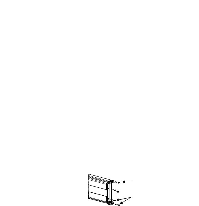
1.Attach a mounting bracket on each end of the signs and replace the end caps.
Follow Steps 1 to 5 of the Wall Mount instructions.
2.However, replace only the bottom three screws for each end cap and torque the screws to 2.7 Nm (24 lb-in).
Do this for each end of both signs.
TIP |
Do NOT fasten the top screws to the end caps. The |
|
top screws are used to fasten the ceiling mounting |
||
|
||
|
||
|
brackets to the end caps in the next step. |
Do NOT fasten this screw to the end cap.
 Fasten these three screws to each end cap.
3.Attach ceiling mounting brackets to all the end caps and torque the screws to 2.7 Nm (24 lb-in).
See Step 2 of the Ceiling Mount instructions.
Publication 2706-UM016D-EN-P - March 2006

1-12 Install InView Marquee Message Display

 Ceiling mounting bracket
4.Match the signs together back-to-back and connect them together.
Follow Steps 7 through 10 of the Wall Mount instructions on page 1-8.
|
Second |
First |
Second |
|
sign |
||
|
sign |
sign |
|
|
|
||
First |
|
First |
Second |
|
mounting |
mounting |
|
sign |
Mounting |
bracket |
bracket |
|
|
|
|
|
brackets |
|
|
5. Use chains (not supplied) to hang the signs from the ceiling.
TIP |
Use chains capable of supporting 4 times the total |
|
weight of the signs. |
||
|
||
|
Publication 2706-UM016D-EN-P - March 2006
Install InView Marquee Message Display |
1-13 |
|
|
Mount the 2706-P72 and 2706-P74 series NEMA 4 and 4x models
To mount the sign:
1.Attach the two sign brackets to a wall, ceiling, or other surface.
Be sure to place the brackets so the bracket flanges face appropriately as shown below. Mount the brackets the following distance apart (measured from the center of the mounting holes in each bracket):
Mounted so flanges are hidden behind the sign 2706-P72CNx: 104.8 cm (41.25 in.) 2706-P74CNx: 165.8 cm (65.25 in.)
Wall or ceiling
Sign brackets, facing in behind the sign
Mounted so flanges show on the sides of the sign 2706-P72CNx: 110.5 cm (43.5 in.)
2706-P74CNx: 171.4 cm (67.5 in.)
Sign brackets, facing out from the sign
|
Do not install the sign directly to drywall or |
|
IMPORTANT |
||
plasterboard. The sign must be fastened to a surface |
||
|
||
|
||
|
capable of supporting at least four times the weight |
|
|
of the sign. |
|
|
|
2.Mount the sign on the sign brackets using the two large hex bolts supplied.
|
|
(0.50 REF) |
Ceiling |
|
|
(0.36 TYP) |
End view, |
|
|
End view, |
|
|
|
ceiling-mounted |
|
|
|
wall-mounted |
|
|
|
|
|
|
|
|
Hex bolt |
|
184.15 |
|
Hex bolt |
|
(7.25 REF) |
|
|
|
|
139.70 (5.50) |
|
30.48 (1.20) |
|
Wall |
|
|
|
69.85 |
|
|
|
(2.75) |
|
19.05
(0.75)
8.74 x 12.70 (0.344 x 0.50) OBRound Slot (3 Places)
3.Tilt the sign to select a viewing angle.
4.To hold the sign in place, insert a Phillips screw (supplied) through one of the small holes on each bracket into the screw hole in the sign case.
Publication 2706-UM016D-EN-P - March 2006

1-14 Install InView Marquee Message Display
Phillips screw |
Ceiling |
Phillips screw |
End view, |
End view, |
|
wall-mounted |
ceiling-mounted |
|
Wall |
|
|
Electrical Connections for 2706-P72 and 2706-P74 Signs
TIP |
Keep a minimum 2.54 cm (1.0 in.) clearance on all |
|
sides of the sign for adequate ventilation. |
||
|
Hazardous voltage. Contact with high voltage may
WARNING
cause death or serious injury. Always disconnect power to sign prior to servicing.
To connect the sign:
Front view, closed
Front view, open
1.Open the front of the sign case by turning the quarter-turn latches to the left with a large screwdriver.
(On the 2706-P72CNx, there are 3 quarter-turn latches; on the 2706-P74CNx there are 4.) Carefully let the front of the case drop forward.
Quarter-turn latches on an 2706-P74 sign
|
Serial |
Power line |
|
Power supply |
filter |
||
connection |
|||
|
Power connection terminal block
 Electrical
opening
 Serial device opening
Publication 2706-UM016D-EN-P - March 2006

Install InView Marquee Message Display |
1-15 |
|
|
Right-end view
2.Feed electrical cable through 2.54 cm (1 in.) water-tight conduit, the outside end of the connector (supplied), the electrical opening in the sign case, and then through the inside end of the connector.
3.Screw the inside and outside ends of the connector together until water-tight.
Front view |
Rubber gasket |
Conduit |
|
Sign case, |
Connector, |
outside end |
|
inside |
|
Electrical opening |
Connector nut, with teeth |
|
|
|
facing the sign case |
4.Strip the electrical wires back 6.35 cm (0.25 in.).
5.Connect the wires by screwing the end of each wire into the power connection.
Line |
Ground |
|
|
GREEN |
Neutral |
||
(Hot) |
|||
w/ |
(Line 2): |
||
BLACK |
|||
Yellow |
WHITE |
||
|
1 LINE |
GROUND |
OR 2 LINE NEUTRAL |
Power connection |
|
|
1 LINE |
GROUND |
OR 2 LINE NEUTRAL |
208 - 240 VAC INPUT |
||
Right-end view
Serial device hole plug/opening
6.If the sign is to be used with serial communications, remove one or both of the hole plugs from the lowest holes on the right end of the sign case.
Otherwise, proceed to Step 7.
TIP |
TB1 can be used for incoming serial connection for |
|
RS-232 or RS-485. The full pinout diagram is shown |
||
|
||
|
||
|
below. |
Publication 2706-UM016D-EN-P - March 2006

1-16 Install InView Marquee Message Display
TB1 Full
Pin |
Pin Name |
Pin |
|
Pin Name |
|
|
|
|
|
|
|
1. |
GND |
|
|
5. |
RS-485(+) |
|
|
|
|
|
|
2. |
+5V |
|
|
6. |
RS-485(-) |
|
|
|
|
|
|
3. |
RS-232 |
TX |
|
7. |
NC |
|
|
|
|
|
|
4. |
RS-232 |
RX |
|
8. |
SHIELD |
|
|
|
|
|
|
7.Connect the incoming serial wires per pinout.
TB1 can be used for incoming RS-485 or RS-232 serial connection. They cannot be connected at the same time.
RS-485 is recommended to reduce undesirable electrical interference.
TB1 RS-485
Pin |
Pin Name |
Pin |
Pin Name |
|
|
|
|
1. |
NC |
5. |
RS-485(+) |
|
|
|
|
2. |
NC |
6. |
RS-485(-) |
|
|
|
|
3. |
NC |
7. |
NC |
|
|
|
|
4. |
NC |
8. |
SHIELD |
|
|
|
|
TB1 RS-232 |
|
|
|
|
|
|
|
Pin |
Pin Name |
Pin |
Pin Name |
|
|
|
|
1. |
GND |
5. |
NC |
|
|
|
|
2. |
NC |
6. |
NC |
|
|
|
|
3. |
RS-232 TX |
7. |
NC |
|
|
|
|
4. |
RS-232 RX |
8. |
NC |
|
|
|
|
|
1 |
|
2 |
TB1 |
3 |
4 |
|
|
5 |
|
6 |
|
7 |
|
8 |
Controller Board |
|
Publication 2706-UM016D-EN-P - March 2006

Install InView Marquee Message Display |
1-17 |
|
|
Mount the 2706-P92C and
2706-P94C Sign
P1 can be used for incoming RS-232 only, although it is optional and not recommended.P1 is intended for RS-232 application downloads and RS-485 terminating resistor connection.
See publication 2706-IN007 for more information on RS-485 termination.
8.Carefully close the front of the sign case and turn the quarter-turn latches to the right with a large screwdriver.
To mount the sign:
1.Attach the two sign brackets to a wall, ceiling, or other surface.
Be sure to place the brackets so the bracket flanges face appropriately as shown below. Mount the brackets the following distance apart (measured from the center of the mounting holes in each bracket).
|
|
Mounted so flanges are hidden behind the sign |
|
Mounted so flanges show on the sides of the sig |
||||||
|
|
|
|
|
|
|||||
|
|
2706-P92C 103.0 cm (40.55 in.) |
|
|
|
2706-P92C: 107.8 cm (43.22 in.) |
|
|
||
|
|
2706-P94C: 194.4 cm (76.55 in.) |
|
Wall |
|
|
||||
|
|
|
|
2706-P94C: 201.2 cm (79.22 in.) |
|
|
||||
|
|
|
|
|
|
|||||
|
|
|
|
or |
|
|
|
|
|
|
|
|
|
|
ceiling |
|
|
|
|
|
|
|
|
|
|
|
|
|
|
|
|
|
|
|
|
|
|
|
|
|
|
|
|
|
|
|
|
|
|
|
|
|
|
|
Sign brackets, facing |
Sign brackets, facing |
|
out from the sign |
||
in behind the sign |
||
|
|
Do not install the sign directly to drywall or |
|
IMPORTANT |
||
plasterboard. The sign must be fastened to a surface |
||
|
||
|
||
|
capable of supporting at least four times the weight |
|
|
of the sign. |
|
|
|
2.Mount the sign on the sign brackets using the hex bolts supplied.
3.Insert the bolts into the far single holes first, until the desired viewing angle is determined.
Publication 2706-UM016D-EN-P - March 2006

1-18 Install InView Marquee Message Display
|
|
|
|
Dimensions are shown in mm (in.) approx. |
|
10.16 |
||
|
|
|
|
|
|
|
||
|
139.16 |
|
|
|
8.74 x 17.48 |
(.40) |
||
|
8.74 x 17.48 |
|
|
33.78 |
||||
|
(5.40) |
|
|
|||||
|
|
|
(.344 x .688) |
|||||
|
(.344 x .688) |
|
|
(1.33) |
||||
|
|
|
|
|
||||
10.16 (.40) |
|
|
|
|
OBROUND |
|||
|
|
OBROUND |
|
|
|
|||
|
|
|
0.572 (14.53) |
|
||||
|
|
|
14.53 (0.572) |
8.74 x 17.48 |
|
|||
33.78 (1.33) |
|
|
|
44.45 44.45 |
|
|||
|
|
14.53 |
14.53 |
|
||||
44.45 |
|
(.344 x .688) |
22.35 |
|||||
22.35 |
44.45 |
(0.572) |
(0.572) |
(1.75) (1.75) |
||||
OBROUND |
(.88) |
|||||||
(.88) |
(1.75) (1.75) |
Ø 7.14 |
|
139.16 |
||||
|
|
10° |
(.281) |
|
Ø 7.14 |
(5.40) |
|
|
|
|
|
38.10 (1.50) |
(.281) |
10° |
|
||
|
|
|
|
|
||||
|
|
|
117.60 (4.63) |
117.60 (4.63) |
|
|
||
|
|
|
|
|
|
|||
|
|
|
38.10 (1.50) |
Ø 7.14 |
|
|
||
|
|
|
|
|
|
|||
|
|
|
3.43 (.135) |
19.30(.76) |
(.281) |
|
|
|
|
|
|
10.16(.40) 10.16(.40) |
|
193.93 |
|
||
|
193.93 |
33.78 |
|
33.78 |
(7.635) |
|
||
|
(7.635) |
(1.33) |
|
(1.33) |
Right Bracket |
|
||
Left Bracket

 Ceiling
Wall
Hex bolt for single hole
Ceiling
End view, wall/ceiling mounted
4.Tilt the sign to select a viewing angle.
5.To hold the sign in place, insert the remaining bolts into the desired viewing angle hole on each bracket.
Wall
Desired viewing angle hole
TIP |
Keep a minimum 2.54 cm (1.0 in.) clearance on all |
|
sides of the sign for adequate ventilation. |
||
|
||
|
Publication 2706-UM016D-EN-P - March 2006

Install InView Marquee Message Display |
1-19 |
|
|
Back-to-back Mount
1.Attach the brackets to the sign in the ceiling mount position with the hex bolts supplied.
2.Match the signs together back-to-back and connect them together using a total of six 5/16” bolts and nuts (not supplied).
|
Attach chains here |
|
First |
Second |
|
sign |
||
sign |
||
|
||
First |
Second |
|
mounting |
mounting |
|
bracket |
bracket |
3.Attach chains (not supplied) to the top mounting holes of the bracket to hang the signs from the ceiling.
TIP |
Use chains capable of supporting 4 times the total |
|
weight of the signs. |
||
|
||
|
Electrical Connections for 2706-P92C and 2706-P94C Signs
HAZARDOUS VOLTAGE
WARNING
• Contact with high voltage may cause death or serious injury. Always disconnect power to sign prior to servicing.
•Maintain Separation of circuits. Route the incoming power directly to the power connection terminal block.
•Do not run the power wiring over the logic board or optional Communication board.
Open the front of the sign case by turning the half-turn latches to the left with a large screwdriver. On the 2706-P92C, there are 3 half-turn latches; on the 2706-P94C there are 5. Carefully let the front of the case drop forward.
Publication 2706-UM016D-EN-P - March 2006

1-20 Install InView Marquee Message Display
Front view, closed
|
Half-turn latches on an 2706-P94C sign |
Communication |
||
|
Electrical |
Power connection |
||
Front view, open |
opening |
|||
terminal block |
||||
|
opening |
|
||
|
|
|
||
4.Feed electrical cable through 12.7 mm (0.5 in.) water-tight conduit, the outside end of the connector (supplied), the electrical opening in the sign case, and then through the inside end of the connector.
5.Screw the inside and outside ends of the connector together until water-tight.
TIP |
Use either of the two holes nearest the power |
|
connection terminal block. |
||
|
||
|
Front view |
Rubber gasket |
Conduit |
|
Sign case, |
Connector, |
outside end |
|
inside |
Connector nut, with teeth |
|
|
|
facing the sign case |
6. Strip the electrical wires back 6.35 mm (0.25 in.).
Publication 2706-UM016D-EN-P - March 2006

Install InView Marquee Message Display |
1-21 |
|
|
7.Insert the wires into the appropriate terminal connection and tighten the screw to 0.79 Nm (7 lb-in).
The terminal block is UL rated for wire ranges of 14 to 8 AWG.
|
Ground |
Line |
GREEN w/ Yellow |
|
|
(Hot) BLACK |
|
1 LINE |
GROUND |
OR 2 LINE NEUTRAL |
Power connection |
|
|
1 LINE |
GROUND |
OR 2 LINE NEUTRAL |
208 - 240 VAC INPUT |
||
Neutral
(Line 2): WHITE
8.Remove the necessary hole plugs before connecting the communications cables.
9.Connect the incoming communication wires per the tables below.
ATTENTION |
Use shielded Ethernet cable. Shielded Ethernet |
|||
cable is required to maintain noise immunity. |
||||
|
|
|
||
|
|
|
||
|
|
|
The 2706-PCable1 is used for downloading |
|
|
|
|
messages only and must be removed after |
|
|
|
|
||
|
|
|
||
|
|
|
downloading is complete. |
|
|
|
|
|
|
TB1 is used for P9x pass-through. TB2 is used for supplying power to the optional InView Legacy Communication board kit.
|
Communication |
Ethernet |
TB1 TB2 |
|
RJ-12 |
||
|
Openings |
|
|||||
|
|
|
|
|
TB3 |
||
|
|
|
|
|
|
|
|
TB1 RS-485 |
|
|
|
|
|
|
|
|
|
|
|
|
|
|
|
Pin |
|
Pin Name |
Pin |
|
Pin Name |
|
|
|
|
|
|
|
|
|
|
1. |
|
GND |
4. |
|
CH A |
|
|
|
|
|
|
|
|
|
|
2. |
|
SHLD |
5. |
|
CH B |
|
|
|
|
|
|
|
|
|
|
3. |
|
COMM |
6. |
|
TERM |
|
|
|
|
|
|
|
|
|
|
Publication 2706-UM016D-EN-P - March 2006

1-22 Install InView Marquee Message Display
1 8
RJ12
|
|
|
|
|
|
|
|
|
|
|
|
|
|
1 |
2 |
3 |
4 |
5 |
6 |
|
+5V NC |
TX RX NC GND |
|||||
TB2 - Aux +5V
Pin |
Pin Name |
|
Pin |
Pin Name |
|
|
|
|
|
|
|
1. |
+5V |
2. |
GND |
|
|
|
|
|
|
|
|
TB3 - RS-232 |
|
|
|
|
|
|
|
|
|
|
|
Pin |
Pin Name |
|
Pin |
Pin Name |
|
|
|
|
|
|
|
1. |
TXD |
4. |
CTS |
|
|
|
|
|
|
|
|
2. |
RXD |
5. |
GND |
|
|
|
|
|
|
|
|
3. |
RTS |
6. |
EGND |
|
|
|
|
|
|
|
|
Ethernet (RJ-45)(1) |
|
|
|
|
|
|
|
|
|
|
|
Pin |
Pin Name |
|
Pin |
Pin Name |
|
|
|
|
|
|
|
1. |
TD+ |
|
5. |
NC |
|
|
|
|
|
|
|
2. |
TD- |
|
6. |
RD- |
|
|
|
|
|
|
|
3. |
RD+ |
|
7. |
NC |
|
|
|
|
|
|
|
4. |
NC |
|
8. |
NC |
|
|
|
|
|
|
|
(1) Use shielded Ethernet cable to maintain noise immunity. |
|
|
|||
Download Port (RJ-12)(1) |
|
|
|
|
|
|
|
|
|
|
|
Pin |
Pin Name |
|
Pin |
Pin Name |
|
|
|
|
|
|
|
1. |
Aux +5V |
4. |
RX |
|
|
|
|
|
|
|
|
2. |
NC |
5. |
NC |
|
|
|
|
|
|
|
|
3. |
TX |
6. |
GND |
|
|
|
|
|
|
|
|
(1)The 2706-PCable1 is used for downloading messages only and must be removed after downloading is complete.
10.Carefully close the front of the sign case and turn the half-turn latches to the right with a large screwdriver.
Publication 2706-UM016D-EN-P - March 2006
Loading...