


 Loading...
8720MC Regenerative
Power Supply
Installation Manual

Important User
Information
Because of the variety of uses for the products described in this publication, those responsible for the application and use of this control equipment must satisfy themselves that all necessary steps have been taken to assure that each application and use meets all performance and safety requirements, including any applicable laws, regulations, codes and standards.
The illustrations, charts, sample programs and layout examples shown in this guide are intended solely for purposes of example. Since there are many variables and requirements associated with any particular installation, Allen-Bradley does not assume responsibility or liability (to include intellectual property liability) for actual use based upon the examples shown in this publication.
Allen-Bradley publication SGI-1.1, Safety Guideline for the Application, Installation and Maintenance of Solid-State Control (avialable from your local Allen-Bradley office), describes some inportant differences between solid-state equipment and electromechanical devices that should be taken into consideration when applying products such as those described in this publication.
Reproduction of the contents of this copyrighted publication, in whole or part, without written permission of Rockwell Automation, is prohibited.
ATTENTION: Identifies information about practices
or circumstances that can lead to personal injury or death, property damage, or economic loss.
Attention help you:
•identify a hazard
•avoid the hazard
•recognize the consequences
Important: Identifies information that is especially important for successful application and understanding of the product.
European Communities
(EC) Directive
Compliance
If this product has the CE mark it is approved for installation within the European Union and EEA regions. It has been designed and tested to meet the following directives.
EMC Directive
This product is tested to meet the Council Directive 89/336/EC Electromagnetic Compatibility (EMC) by applying the following standards, in whole or in part, documented in a technical construction file:
•EN 50081-2 EMC - Generic Emission Standard, Part 2 - Industrial Environment
•EN 50082-2-EMC - Generic Immunity Standard, Part 2 - Industrial Environment
This product is intended for use in an industrial environment.
Low Voltage Directive
This product is tested to meet Council Directive 73/23/EEC Low Voltage, by applying the safety requirements of EN 61131-2 Programmable Controllers, Part 2 - Equipment Requirements and Tests. For specific information required by EN 61131-2, see the appropriate sections in this publication, as well as the Allen-Bradley pulbication Industrial Automation Wiring and Grounding Guidelines For Noise Immunity, publication 1770-4.1.
This equipment is classified as open equipment and must be mounted in an enclosure during operation to provide safety protection.

Table of Contents
Contents of This
Manual
About 8720MC-RSP
Regenerative Power
Supply
Installation
Wiring
Chapter 1
Introduction .................................................................................. |
1-1 |
Finding Information ...................................................................... |
1-1 |
Assumptions About the Audience ................................................ |
1-2 |
Notes on Handling the 8720MC-RPS Regenerative Power |
|
Supply .......................................................................................... |
1-3 |
Chapter 2
Model Numbers of the 8720MC-RPS Regenerative Power |
|
Supply and its Accessories .......................................................... |
2-1 |
Power Rating ................................................................................ |
2-2 |
Appearance of the 8720MC-RPS Regenerative Power Supply .. |
2-2 |
Appearance of Model 8720MC-RPS027 and |
|
8720MC-RPS065 ................................................................... |
2-2 |
Appearance of Model 8720MC-RPS190 ................................ |
2-4 |
Main Components and Locations ................................................ |
2-5 |
Terminal Blocks on the Main Circuit ............................................ |
2-10 |
Main Power Terminal Block (TB1) for Model 8720MC- |
|
RPS027 and 8720MC-RPS065 .............................................. |
2-12 |
Control Power Terminal Block (TB2) for Model 8720MC- |
|
RPS027 and 8720MC-RPS065 .............................................. |
2-12 |
Mainl Power Terminal Bar for Model 8720MC-RPS190 ........ |
2-13 |
Control Power Terminal Block (TB2) and Control Terminal |
|
Block (TB4) for Model 8720MC-RPS190 ............................... |
2-13 |
Regulator Board ........................................................................... |
2-14 |
Jumpers and Switches ........................................................... |
2-15 |
Sequence Signal Terminal Block (TB3) ................................. |
2-17 |
Chapter 3
Installation Site ............................................................................. |
3-1 |
Environmental Conditions to be Met ...................................... |
3-1 |
Required Total Area ............................................................... |
3-2 |
Recommended Air Flow Clearance ....................................... |
3-7 |
Notes on Installation .................................................................... |
3-7 |
Chapter 4
Recommended Wire Sizes .......................................................... |
4-1 |
Recommended Wire Sizes for Power Wiring to the Main |
|
Power Terminal Block (TB1) and the Main Power Terminal |
|
Bars ........................................................................................ |
4-2 |
Recommended Wire Sizes for Power Wiring to the Control |
|
Power Terminal Block (TB2) and the Control Terminal |
|
Block (TB4) ............................................................................. |
4-2 |
AC Input Power Wiring fot Model 8720MC-RPS027 and |
|
8720MC-RPS065 ......................................................................... |
4-3 |
When Model 8720MC-RPS027 or 8720MC-RPS065 is |
|
operated in the Power Regeneration Mode only ................... |
4-7 |
When Model 8720MC-RPS027 and 8720MC-RPS065 are |
|
adapted to Capacitors having large capacity ......................... |
4-9 |
Installing Circuit Breaker ........................................................ |
4-11 |
ii |
Table of Contents |
Start and Adjustment
Operation Panel
Parameters
Installing Main Magnetic Contactor ........................................ |
4-11 |
Installing Reactor .................................................................... |
4-12 |
Installing Varistor .................................................................... |
4-13 |
Installing Harmonic Filter ........................................................ |
4-14 |
Installing Input Fuses ............................................................. |
4-14 |
Installing Line Filters .............................................................. |
4-14 |
Bus Bar and Output Fuses ..................................................... |
4-15 |
AC Input Power Wiring for Model 8720MC-RPS190 ................... |
4-16 |
When Model 8720MC-RPS190 is operated in the Power |
|
Regeneration Mode only ........................................................ |
4-22 |
When Model 8720MC-RPS190 is adapted to Capacitors |
|
having large capacity ............................................................. |
4-24 |
Installing Circuit Breaker - 8720MCRPS190.......................... |
4-26 |
Installing ACL Unit (Reactor Assembly) - 8720MC- |
|
RPS190 .................................................................................. |
4-26 |
Installing Fuses - 8720MC-RPS190 ....................................... |
4-27 |
Installing 8720MC-EF190-VB EMC Filter Unit ....................... |
4-28 |
Installing DC Bus Power Output Wiring - All RPS units .............. |
4-29 |
Grounding the 8720MC-RPS Regenerative Power Supply ......... |
4-29 |
Wiring To Comply with EMC ........................................................ |
4-30 |
Sequence Signal Wiring ............................................................... |
4-32 |
Sequence Signal Wiring ......................................................... |
4-32 |
Operation Timing of Sequence Control Signals .................... |
4-33 |
Installing Ribbon Cables .............................................................. |
4-36 |
Notes on Wiring............................................................................ |
4-37 |
Chapter 5
Checking before Powering up the 8720MC-RPS Regenerative |
|
Power Supply .................................................................................. |
5-1 |
Verifying the Installation ............................................................ |
5-1 |
Verifying the Rating of the 8720MC-RPS Regenerative |
|
Power Supply ............................................................................ |
5-2 |
Verifying Wiring ......................................................................... |
5-2 |
Powering up the 8720MC-RPS Regenerative Power Supply ........ |
5-2 |
Operating the 8720MC-RPS Regenerative Power Supply ............. |
5-3 |
Chapter 6
Configuration of the Operation Panel ............................................. |
6-1 |
Operation Modes ............................................................................. |
6-1 |
Monitor Mode ............................................................................. |
6-2 |
Program Mode ........................................................................... |
6-3 |
Display ............................................................................................. |
6-3 |
Keypad ............................................................................................ |
6-4 |
Status LEDs .................................................................................... |
6-5 |
Chapter 7
Parameter Types ............................................................................. |
7-1 |
Protecting Parameters with Password ............................................ |
7-3 |
Displaying and Changing Parameter Values .................................. |
7-3 |
User Parameters ............................................................................. |
7-3 |
Factory Parameters ........................................................................ |
7-5 |
Table of Contents |
iii |
Error Codes and
Warning Buzzer
Inspecting Trouble
and Recovering
Special Replacement
Parts
Outline Drawings of
the Peripheral Devices
Technical Specifications
Default Parameter Settings
Control Block Diagram
Chapter 8
Contents of Error Codes and Recovering ...................................... |
8-2 |
Accessing and Clearing the Entries in the Error Log ..................... |
8-5 |
Recovering from Fatal Error ........................................................... |
8-6 |
Warning Buzzer ............................................................................... |
8-6 |
Chapter 9
Safety Precautions .......................................................................... |
9-1 |
Preliminary Review ......................................................................... |
9-2 |
Troubleshooting Flow Charts .......................................................... |
9-2 |
8720MC-RPS Regenerative Power Supply Does Not Run ...... |
9-2 |
DC Bus Voltage Does Not Go Up ............................................. |
9-3 |
Chapter 10 |
|
Chapter 11 |
|
Outline Drawings of the Reactors ................................................... |
11-1 |
Outline Drawing of the Varistors ..................................................... |
11-3 |
Outline Drawing of the Harmonic Filters ......................................... |
11-4 |
Outline Drawing of the Line Filters ................................................. |
11-5 |
8720MC-EF190-VB EMC Filter Unit for Model 8720MC-RPS190BM |
|
and 8720MC-RPS190BS ................................................................ |
11-7 |
Appendix A
Appendix B
Appendix C
iv |
Table of Contents |
End of Table of Contents

Chapter 1
Introduction
Finding Information
Contents of This Manual
The 8720MC-RPS Regenerative Power Supply Bidirectional Converter is a sinusoidal PWM converter which can control increase of DC bus voltage and perform continuous power generation.
The 8720MC-RPS Regenerative Power Supply, therefore, can be used as power supply unit for various drives and inverter units.
This instruction manual covers the 8720MC-RPS Regenerative Power Supply for 380-460 VAC, and describes the hardware
and the start-up and programming procedure for the 8720MC-RPS Regenerative Power Supply. Read and understand this manual before proceeding.
All the following units are UL/C-UL listed:
8720MC-RPS027BM,
8720MC-RPS065BM and 8720MC-RPS065BS, 8720MC-RPS190BM and 8720MC-RPS190BS
Also, the Declaration of Conformity with the requirement for CE Mark was already issued for all the units.
The 8720MC-RPS Regenerative Power Supply is a bidirectional converter with the following features:
•Use of chopper type voltage increasing method with sinusoidal pulse-width-modulated (PWM) waveform control.
•Programmable DC bus voltage.
•Continuous power regeneration.
•Attenuation of the higher order harmonics in the line current.
•Safety interlocks and protection.
This manual describes the details of the 8720MC-RPS Regenerative Power Supply in order to provide the user with a complete understanding of the installation, wiring, operation and adjustment of the product. As an aid in finding information in this manual, each chapter is briefly described below:
•Chapter 1: Contents of This Manual
Provides situation for acquiring UL Marks and CE Marks for the 8720MC-RPS Regenerative Power Supply and information on how this manual is organized and where to find additional information.
1-2 |
Contents of This Manual |
Assumptions About the
Audience
•Chapter 2: About 8720MC-RPS Regenerative Power Supply
Identifies components of the 8720MC-RPS Regenerative Power Supply, shows their locations, and describes the main components.
•Chapter 3: Installation
Describes how to mount the 8720MC-RPS
Regenerative Power Supply properly.
•Chapter 4: Wiring
Describes how to properly wire and connect the 8720MC-RPS Regenerative Power Supply.
•Chapter 5: Start and Adjustment
Provides information on how to perform a final check before power is applied, and instructions on basic operation.
•Chapter 6: Operation Panel
Describes the composition and contents of the operation panel.
•Chapter 7: Parameters
Provides detailed description of each parameter.
•Chapter 8: Error Codes and Warning Buzzer
Describes contents of error codes and how to correct problems.
•Chapter 9: Inspecting Trouble and Recovering
Describes how to inspect and troubleshoot the 8720MC-RPS Regenerative Power Supply.
•Chapter 10: Special Replacement Parts
Provides a list of required replacement parts.
•Chapter 11: Outline Drawings of the Peripheral Devices
Provides outline dimensions of converters, reactors, varistors, harmonic filters and line filters.
•Appendix A: Technical Specifications
Lists specifications of the 8720MC-RPS
Regenerative Power Supply in table form.
•Appendix B: Default Parameter Settings
Provides the default values of the parameters in table form.
•Appendix C: Control Block Diagram
Provides a control block diagram.
This manual is intended for electrical personnel familiar with the operation of this equipment and the hazards involved.
Contents of This Manual |
1-3 |
Notes on Handling the 8720MC-RPS Regenerative Power Supply
The following three labels are put on the 8720MC-RPS Regenerative Power Supply, advising the user of the notes on handling the unit. Read and understand the contents before using the unit.
!PWR
CAUTION!
WHEN YOU APPLY POWER
AGAIN, VERIFY THAT |
B6013 |
THIS LAMP "PWR" IS |
|
TURNED OFF. |
ME- |
! DANGER
RISK OF ELECTRICAL SHOCK. DISCONNECT INPUT
POWER BEFORE SERVICING EQUIPMENT.
ME-B6015
CAUTION !
THIS EQUIPMENT MUST BE MOUNTED IN A SUITABLE UL RECOGNIZED ENCLOSURE OR NEMA ENCLOSURE. USE COPPER 60/75 DEGREE C WIRE ONLY.
1-4 |
Contents of This Manual |
End of Chapter

Chapter 2
About 8720MC-RPS
Regenerative Power Supply
Model Numbers of the 8720MCRPS Regenerative Power Supply and its Accessories
This chapter describes model numbers, major components, their locations, and terminal blocks of 8720MC-RPS Regenerative Power Supply.
For operation of the 8720MC-RPS Regenerative Power Supply, a line reactor is required for each incoming phase as well as a varistor, a harmonic filter and a contactor. The following figure shows the model numbers of the 8720MC-RPS Regenerative Power Supply and its accessories.
Regenerative Power Supply
8720MC-RPSxxxvm-opt
BASE CATALOG NUMBER - CONVERTER
REGENERATIVE POWER SUPPLY SIZE 027 = 27 amp
065 = 65 amp
190 = 190 amp
INPUT VOLTAGE
B = 380 TO 460 VAC
TYPE
M = master
S = slave
See Note 1
Note 1: Blank includes the 8720MC - RPS only as a spare part.
HV2 option includes the 8720MC - RPS as well as 8720MC-HF-B2 harmonic filter and 8720MC-VA-B varistor. HV2 option, however, is applied only to 8720MC-RPS027 and 8720MC-RPS065.
Line Reactor
8720MC-LRxx-ayyyb
Inductance as % Voltage Drop 03 = 3% 05 = 5% 10 = 10% 14 = 14%
Enclosure
blank = open
A = NEMA type 1
Current Rating
032 = 32 Amp
048 = 48 Amp
062 = 60 Amp
070 = 80 Amp
100 = 100 Amp
Voltage
B = 380 to 460 VAC
Harmonic Filter
8720MC-HF-b
Voltage
B2 = 380 to 460 VAC
Varistor
8720MC-VA-b
Voltage
B = 380 to 460 VAC
EMC Filter Unit
8720MC-EFxxx-Vb
Current Rating 190 = 190 Amp
Voltage
B = 380 to 460 VAC
2-2 |
About 8720MC-RPS Regenerative Power Supply |
Power Rating
Power rating of 8720MC-RPS Regenerative Power Supply depends on the number of units connected in parallel as shown in the table below. Up to three units can be connected.
Table 2.1
Kind, Connection and Power Ratings
Kind of Unit |
Connection |
Model Number |
Power Rating |
|
|
|
|
15 kW |
Single Unit |
8720MC-RPS027BM x 1 |
15 kW |
|
|
|
|
37 kW |
Single Unit |
8720MC-RPS065BM x 1 |
37 kW |
|
|
|
|
|
Two paralleled units |
8720MC-RPS065BM + |
75 kW |
|
|
8720MC-RPS065BS x 1 |
|
|
|
|
|
|
Three paralleled units |
8720MC-RPS065BM + |
110 kW |
|
|
8720MC-RPS065BS x 2 |
|
|
|
|
|
125 kW |
Single Unit |
8720MC-RPS190BM x 1 |
125 kW |
|
|
|
|
|
Two paralleled units |
8720MC-RPS190BM + |
250 kW |
|
|
8720MC-RPS190BS x 1 |
|
|
|
|
|
|
Three paralleled units |
8720MC-RPS190BM + |
375 kW |
|
|
8720MC-RPS190BS x 2 |
|
|
|
|
|
Appearance of the 8720MC-
RPS Regenerative Power
Supply
Appearance of Model 8720MC-RPS027 and 8720MC-RPS065
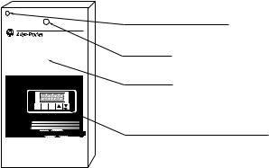
The figure below shows the front view of the 8720MC-RPS027 and 8720MC-RPS065 covered by the front cover.
The operation panel (only for master unit) and the power lamp can be seen through the front cover. All the terminals blocks to connect wiring are covered by the front cover.
RST PRG ENT |
8720 MC |
REGENERATIVE POWER SUPPLY |
Unit Front View
Hole for Cover Fixing Screw <1
Power Lamp
Front Cover
Operation Panel (only for Master Unit)
1> Model 8720MC-RPS027 has the cover fixing screw
at the right upper corner instead of the left upper corner.

About 8720MC-RPS Regenerative Power Supply |
2-3 |
When the front cover is removed from the 8720MC-RPS027 and 8720MC-RPS065 , the main power terminal block (TB1) and the Regulator Board (only for master unit) will appear as shown in the following figure. To remove the front cover, first remove the screw at the upper left corner of the unit, and then lift up the cover. Note, however, that Model 8720MC-RPS027 has the cover fixing screw at the upper right corner instead of the upper left corner. Do not drop the screw from the cover.
POWER
RST PRG ENT |
Unit After Removing Front Cover
Main Power Terminal Block (TB1)
Regulator Board (only for Master Unit)
Sequence Signal Terminal Block (TB3)
The control power terminal block (TB2) for Model 8720MCRPS027 and 8720MC-RPS065 will be disclosed as shown in the figure below, when the Regulator Board is opened to the left hand side by removing the two fixing screws on the right hand side of the bracket supporting the Regulator Board.
Unit After Removing Regulator Board
POWER
Control Power Terminal Block (TB2)

2-4 |
About 8720MC-RPS Regenerative Power Supply |
Appearance of Model 8720MC-RPS190
The figure below shows the front view of the 8720MC-RPS190 covered by the front cover.
This unit has the main power terminals L1 to L3 at the top of the unit, and DC bus terminals P and N at the bottom of the unit.
|
L2 L1 |
Main Power Terminals |
|
L3 |
|
|
|
Unit Front View |
|
|
Hole for Cover Fixing Screw |
|
|
Power Lamp |
|
|
Front Cover |
|
RST PRG ENT |
|
|
8720 MC |
Operation Panel (only for Master Unit) |
|
REGENERATIVE POWER SUPPLY |
|
P |
N |
DC Bus Terminals |
When the front cover is removed from the 8720MC-RPS190 Regenerative Power Supply, the Control Power Terminal Block (TB2), the Control Terminal Block (TB4), the Regulator Board (only for master unit) and Sequence Signal Terminal Block (TB3) will appear as shown in the following figure.
Fuse1
Fuse2
Fuse3
|
L1AUX |
|
L2AUX |
|
L3AUX |
|
PR1 |
|
PR2 |
|
PR3 |
|
+24V3 |
|
0V3 |
|
SENS |
|
+24V2 |
|
0V2 |
|
MC1 |
|
MC2 |
RST PRG |
ENT |
Unit After Removing Front Cover
Control Power Terminak Block (TB2)
Control Terminal Block (TB4)
Regulator Board (only for Master Unit)
Sequence Signal Terminal Block (TB3)

About 8720MC-RPS Regenerative Power Supply |
2-5 |
Main Components and
Locations
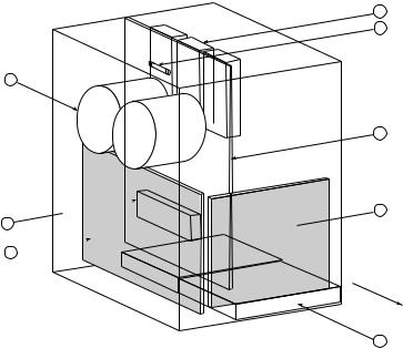
Model 8720MC-RPS027BM has the following main components. The identification numbers provided correspond to the numbers used in the following figure. The main components are included in the special replacement part list shown in Chapter 10.
1.Regulator Board (BDSR) (only master unit has a Regulator Board, not on slave unit)
2.Power Interface Board (PIFS)
3.Driver Board (RCPB)
4.Bus Capacitors
5.Cooling Fan
6.Power Modules
7.Fuse-1
8.Precharge/Discharge Resistor
The following figure shows the locations of the main components of Model 8720MC2-RPS027BM.
4
8
7
3
1
6 
2
Unit Front Side
5
2-6 |
About 8720MC-RPS Regenerative Power Supply |
Model 8720MC-RPS065BM and 8720MC-RPS065BS have the following main components.
1.Regulator Board (BDSR) (only master unit has a Regulator Board, not on slave unit)
2.Power Interface Board (PIFS)
3.Driver Board (RCPB)
4.Bus Capacitors
5.Cooling Fan
6.Power Modules
7.Fuse-1
8.Precharge/Discharge Resistor
The following figure shows the locations of main components of Model 8720MC-RPS065BM and 8720MC-RPS065BS.
6
7
4
3
 1 8
1 8 
2 
Unit Front Side
5

About 8720MC-RPS Regenerative Power Supply |
2-7 |
Model 8720MC-RPS190BM and 8720MC-RPS190BS have the following main components.
1.Regulator Board (BDSR) (only master unit has a Regulator Board, not on slave unit)
2.Power Interface Board (PIFS)
3.Bus Capacitors
4.Cooling Fan
5.Power Modules
6.Fuses 1, 2, 3
The following figure shows the locations of main components of
Model 8720MC-RPS190BM and 8720MC-RPS190BS.
5
6
3 |
FU1 |
|
FU2 |
|
FU3 |
1
2
Unit Front Side
4

2-8 |
About 8720MC-RPS Regenerative Power Supply |
Model 8720MC-RPS027 and 8720MC-RPS065 are composed of the following components.
1)8720MC-RPS
2)Line filter for main circuit*
3)Line filter for sequence power*
4)Circuit breaker
5)AC input fuse
6)DC output fuse
7)Varistor
8)Harmonic filter
9)Main magnetic contactor
10)Reactor
*Not necessary when compliance with CE mark is not required.
The following figure shows system configuration of 8720MCRPS027 and 8720MC-RPS065.
8720MC-RPSxxxvm-HV2
7) Varistor |
|
8720MC-VA-B |
1) 8720MC-RPS |
2)Line Filter for Main Circuit*
4) Circuit |
Breaker |
|
9) Main |
10) |
5) AC |
Magnetic Reactor |
|
Input Fuse |
Contactor 8720MC-LR |
|
ss4000
Synchronous Rectifier
RST PRG ENT |
6) DC Output
Fuse |
3) Line Filter for |
|
|
|
|
|
|
|
|
|
|
|
|
|
||||
|
|
|
|
|
|
|
|
|
|
|
|
|
|||||
|
|
|
|
|
|
|
|
|
|
|
|
|
|||||
|
|
|
|
|
|
|
|
|
|
|
|
|
|||||
8) Harmonic Filter |
|||||||||||||||||
|
Sequence Power* |
||||||||||||||||
|
|
|
8720MC-HF-B2 |
||||||||||||||
|
|
|
|
|
|
||||||||||||
|
|
|
|
|
|
|
|
|
|
|
|
|
|
|
|
|
|
|
|
|
|
|
|
|
|
|
|
|
|
|
|
|
|
|
|
|
|
|
|
|
|
|
|
|
|
|
|
|
|
|
|
|
|
About 8720MC-RPS Regenerative Power Supply |
2-9 |
Model 8720MC-RPS190 is composed of the following components.
1)8720MC-RPS
2)Circuit breaker
3)AC input fuse
4)DC output fuse
5)EMC filter unit
6)ACL unit
The following figure shows system configuration of Model 8720MC-RPS190.
1) 8720MC-RPS
2) Circuit |
|
5) EMC |
|
|
3) AC Input |
Filter Unit |
6) ACL Unit |
|
|
Breaker |
Fuse |
8720MC-EF |
8720MC-LR |
POWER |
ss4000
Synchronous Rectifier
RST PRG ENT |
4) DC Output
Fuse |
For more information, refer to Chapter 4 of this manual.
2-10 |
About 8720MC-RPS Regenerative Power Supply |
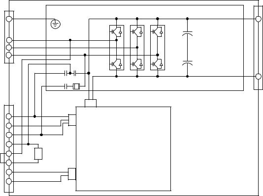
Terminal Blocks on the Main Circuit
This section provides the main circuit block diagram and the description of the main power terminal block (TB1) and the control power terminal block (TB2). The main circuit block diagram for Model 8720MC-RPS027BM, 8720MC-RPS065BM and 8720MCRPS065BS is shown in Figure 2.1.
|
|
Figure 2.1 |
|
|
Terminal Blocks on the Main Circuit for RPS027 and RPS065 units |
|
|
TB1 |
|
TB1 |
|
G |
|
P |
|
|
+ |
L1 |
|
|
L2 |
|
|
L3 |
|
+ |
|
|
|
|
PR |
DIS |
|
|
N |
|
PR FUSE1 |
|
|
|
Driver Board RCPB |
|
TB2 |
CN17 |
|
|
|
L1AUX |
|
CN16 |
L2AUX |
|
|
L3AUX |
|
|
PR1 |
|
|
PR2 |
Precharge/ |
|
Discharge |
|
|
PR3 |
Resistor |
|
|
|
|
MC1 |
|
CN5 |
MC2 |
|
|
|
Power Interface Board PIFS |
|
|
|
|
1> The G terminal for Model 8720MC-RPS027 is located on the front surface of the chassis.
About 8720MC-RPS Regenerative Power Supply |
2-11 |
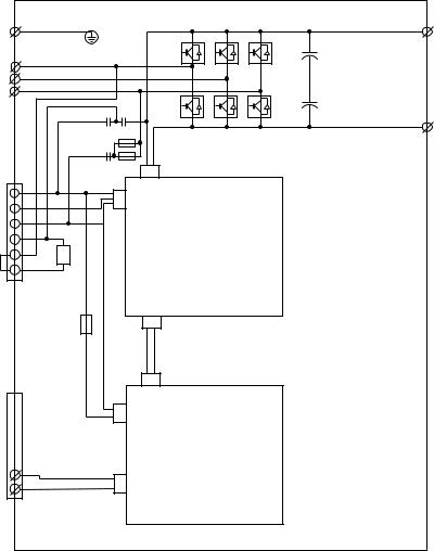
Figure 2.2 shows the main circuit block diagram for Model 8720MC-RPS190BM and 8720MC-RPS190BS.
Figure 2.2
Terminal Blocks on the Main Circuit for RPS190 unit
G |
P |
|
|
BDI |
|
L1 |
|
|
L2 |
|
|
L3 |
BDI |
|
PR |
DIS |
|
|
N |
|
|
Fuse 2 |
|
PR |
|
|
|
Fuse 1 |
|
TB2 |
CN17 |
|
L1AUX |
CN16 |
|
L2AUX |
||
|
||
L3AUX |
|
|
PR1 |
|
|
PR2 |
|
|
PR3 |
|
|
Precharge/ |
|
|
Discharge |
|
|
Resistor |
Power Interface Board PIFS |
|
|
||
Fuse 3 |
CN5 |
|
TB4 |
CN5 |
|
|
||
|
CN16 |
|
MC1 |
CN20 |
|
MC2 |
||
|
APS |
2-12 |
About 8720MC-RPS Regenerative Power Supply |
Main Power Terminal Block (TB1) for Model 8720MC-RPS027 and 8720MC-RPS065
The table below provides the information of the terminals on use of the terminals on the main power terminal block (TB1) for Model 8720MC-RPS027 and 8720MC-RPS065.
Terminal Name |
Symbol |
Description |
|
|
|
Main Power |
L1, L2, L3 |
To connect three-phase AC input power to |
Terminals |
|
the main circuit. |
|
|
For 460 V unit: 380 to 460 VAC +10%, |
|
|
-15%, 50/60 Hz +/-5% |
|
|
|
DC Bus Terminals |
P, N |
To connect the 8720MC-RPS Regenerative |
|
|
Power Supply to load equipment. |
|
|
|
Grounding Terminal |
G |
To ground the 8720MC-RPS Regenerative |
|
|
Power Supply. |
|
|
|
Control Power Terminal Block (TB2) for Model 8720MC-RPS027 and 8720MC-RPS065
The table below describes the terminals on the control power terminal block (TB2) for Model 8720MC-RPS027 and 8720MC-RPS065.
Terminal Name |
Symbol |
Description |
|
|
|
Control Power Terminals |
L1AUX, |
To connect three-phase AC input power to the |
|
L2AUX, |
control circuit. |
|
L3AUX |
For 460 V unit: 380 to 460 VAC +10%, -15%, |
|
|
50/60 Hz +/-5% |
Terminals to Connect |
PR1, |
To connect precharge/discharge resistor. |
Precharge/Discharge |
PR2, |
When the built-in resistor is used: |
Resistor |
PR3 |
Jumper between PR2 and PR3, and open |
|
|
PR1. |
|
|
When an external resistor is used: |
|
|
Connect the resistor between PR1 and |
|
|
PR2, and open PR3. |
|
|
When the unit is connected for power |
|
|
regeneration mode only: |
|
|
Open all the terminals PR1, PR2 and |
|
|
PR3. |
Control Terminals for |
MC1, |
To be used as the control terminals for the |
Main Magnetic Contactor |
MC2 |
main magnetic contactor (rated for 250 VAC/ |
|
|
1 Amp or 30 VDC/1 Amp). |
About 8720MC-RPS Regenerative Power Supply |
2-13 |
Main Power Terminal Bar for Model 8720MC-RPS190
The table below describes the terminals on the main power terminal bar for Model 8720MC-RPS190.
Terminal Name |
Symbol |
Description |
|
|
|
Main Power |
L1, L2, L3 |
To connect three-phase AC input power to |
Terminals |
|
the main circuit. |
|
|
For 460 V unit: 380 to 460 VAC +10%, |
|
|
-15%, 50/60 Hz +/-5% |
|
|
|
DC Bus Terminals |
P, N |
To connect the 8720MC-RPS Regenerative |
|
|
Power Supply to load equipment. |
|
|
|
Grounding Terminal |
G |
To ground the 8720MC-RPS Regenerative |
|
|
Power Supply. |
|
|
|
Control Power Terminal Block (TB2) and Control Terminal Block (TB4) for Model 8720MC-RPS190
The table below describes the terminals on the control power terminal block (TB2) and the terminals on the control terminal block (TB4) for Model 8720MC-RPS190.
Terminal Name |
|
Symbol |
Description |
|
|
|
|
|
|
Control Power |
T |
L1AUX, |
To connect three-phase AC input power to the |
|
Terminal |
B |
L2AUX, |
control circuit. |
|
|
2 |
L3AUX |
For 460 V unit: 380 to 460 VAC +10%, -15%, |
|
|
|
|
50/60 Hz +/-5% |
|
|
|
|
|
|
Terminals to Connect |
|
PR1, |
To connect precharge/discharge resistor. |
|
Precharge/Discharge |
|
PR2, |
When the built-in resistor is used: |
|
Resistor |
|
PR3 |
Jumper between PR2 and PR3, and open |
|
|
|
|
PR1. |
|
|
|
|
When an external resistor is used: |
|
|
|
|
Connect the resistor between PR1 and |
|
|
|
|
PR2, and open PR3. |
|
|
|
|
When the unit is connected for power |
|
|
|
|
regeneration mode only: |
|
|
|
|
Open all the terminals PR1, PR2 and |
|
|
|
|
PR3. |
|
|
|
|
|
|
AC Reactor Fan |
T |
+24V3 |
To supply AC power to the fan for the AC reactor |
|
Power Terminals |
B |
0V3 |
unit through the EM4000 EMC filter unit. |
|
|
4 |
|
|
|
Terminals for Fan Fault |
SENS |
To enter fault signal of the fan for the AC reactor |
|
|
Signal |
|
|
unit. |
|
|
|
|
|
|
Power Terminals for |
|
+24V2 |
To supply power to the main magnetic contactor |
|
Main Magnetic |
|
0V2 |
and the fan for the cabinet fan through the |
|
Contactor MC |
|
|
8720MC-EF190 EMC filter unit. |
|
and Optional Fan |
|
|
|
|
Control Terminaks for |
|
MC1 |
To be used as the control terminals for the main |
|
Main Magnetic |
|
MC2 |
magnetic contactor. |
|
Contactor |
|
|
|
|
|
|
|
|
|
2-14 |
About 8720MC-RPS Regenerative Power Supply |
Regulator Board
The Regulator Board exists only on master unit. The slave unit for parallel connection has no Regulator Board and is controlled by the microprocessor of the Regulator Board on the master unit.
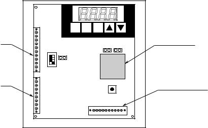
The 8720MC-RPS Regenerative Power Supply regulation is performed by a microprocessor on the Regulator Board. The figure below shows the locations of the main components on the Regulator Board. The operation of the 8720MC-RPS Regenerative Power Supply is adjusted by the parameters set by the keypad.
READY |
|
A |
|
FAULT |
|
V |
|
PROGRAM |
|
kW |
|
RST PRG |
ENT |
|
|
CN2 |
JP1 |
JP3 |
|
SW7 |
|||
|
|
||
JP2 |
|
|
|
CN1 |
SW6 |
||
Microprocessor
Sequence Signal
Terminal Block (TB3)
•PWM Gating Signals
Based on the output of the current/voltage control loop, the Regulator Board sends PWM gating signals through the Power Interface Board to the Power Modules (transistors), producing a pulse-width-modulated (PWM) waveform.
•Sequence Output Signals
Sequence output signals are provided from the sequence signal terminal block (TB3) of the Regulator Board to indicate the unit status .
•Four-character Display and Six LEDs
A four-character seven-segment LED display is used to monitor values, parameter numbers, parameter values, and error codes. Six LEDs show the display mode of the operation panel and the units of the monitored values.

About 8720MC-RPS Regenerative Power Supply |
2-15 |
|
|
|
|
Jumpers and Switches
ATTENTION: Only qualified electrical personnel familiar with the construction and operation of this equipment and the hazards involved should set jumpers and switches. Read and understand this manual in its entirety before proceeding. Failure to observe this precaution could result in severe bodily injury or loss of life.
ATTENTION: Do not press the reset button switch (SW6) during operation. Also, do not alter the setting of any jumpers and switches during operation.
Failure to observe this precaution could result in destruction of the equipment, severe bodily injury or loss of life.
ATTENTION: Do not alter the settings of any jumpers not described in this manual. Failure to observe this precaution could result in damage to, or destruction of, the equipment.
The jumpers JP1 to JP3 and the switches SW6 and SW7 are set before shipment from factory. If you need to change the jumpers and/or switch settings, read and understand the following description of these jumpers and switches before proceeding.
•Jumper JP1 to Enable Operation
Short this jumper to start switching operation of transistors of the 8720MC-RPS Regenerative Power Supply when the RUN sequence input is enabled. This jumper should always be kept closed.
•Jumper JP2 to Enable Inspection Mode Keep this jumper open always.
•Reset Switch SW6
Pressing this switch resets the CPU.
Important: Do not press the reset switch SW6 during operation.
•Switch SW7 to Enable Base Block
This switch is used to stop switching of transistors that produce PWM waveform by interrupting the base signal from the Power Modules. To interrupt the base signal, turn the switch to the OFF side.
As shown in the figure below, SW7 consists of four switches, and SW7-1 to SW7-3 can be allocated to the master unit and slave units 1 and 2. In the case of a master with paralleled slave units, it is possible to interrupt the base signal of each unit by turning the corresponding switch to the OFF side. SW7-4 must always be kept to the OFF side.

2-16 |
About 8720MC-RPS Regenerative Power Supply |
When two units are connected in parallel, turn the switches SW7-1 and SW7-2 to the ON side, and when three units are connected in parallel, turn the switches SW7-1 through SW7-3 to the ON side.
|
|
|
|
|
|
SW7-4 |
|
|
|
|
|
|
|
Slave Unit 2 |
|
|
|
|
|
SW7-3 |
|
|
|
|
|
||
Slave Unit 1 |
|
|
|
|
|
SW7-2 |
|
|
|
|
|
||
Master Unit |
|
|
|
|
|
SW7-1 |
|
|
|
|
|
||
|
|
|
|
|
|
|
|
ON |
OFF |
||||
ENABLE |
BASE BLOCK |
|||||
Keep SW7-4 always to the OFF side.
When the switch is turned to the OFF side, the base signal is interrupted, and the unit will be in the OFF condition.
When the switch is turned to the ON side, the base signal is kept ON, and PWM switching will continue.
About 8720MC-RPS Regenerative Power Supply |
2-17 |
|
|
|
|
|
|
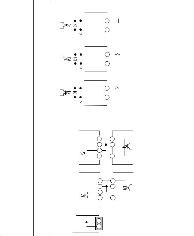
Sequence Signal Terminal Block (TB3) |
||||||||||||||||||||||||||||||
|
|
|
|
As shown in the figure in page 2-14, there is a sequence signal |
||||||||||||||||||||||||||||||
|
|
|
|
terminal block (TB3) on the Regulator Board. The following table |
||||||||||||||||||||||||||||||
|
|
|
|
provides the information on each terminal of TB3. |
||||||||||||||||||||||||||||||
|
|
|
|
|
|
|
|
|
|
|
|
|
|
|
|
|
|
|
|
|
|
|
|
|
|
|
|
|
|
|
|
|
|
|
|
Name of Terminal |
Symbol |
Description |
|
|
|
|
|
|
|
|
|
|
|
|
|||||||||||||||||||
|
|
|
|
|
|
|
|
|
|
|
|
|
|
|
|
|
|
|
|
|
|
|
|
|
|
|
|
|
|
|
|
|
|
|
|
Sequence Input |
MC |
Enter the supplemental contact signal (normally open contact) of the main magnetic contactor.* |
|||||||||||||||||||||||||||||||
|
Signals |
|
|
|
|
|
|
|
|
|
|
4.7K |
|
|
|
|
|
|
|
|
|
|
|
|
MC |
* Because driving current of sequence input signals |
||||||||
|
|
|
|
|
|
|
|
|
|
|
|
|
|
|
|
|
|
|
|
|
|
|
||||||||||||
|
|
|
|
|
|
|
|
|
|
|
|
|
|
|
|
|
|
|
|
|
|
|
|
|||||||||||
|
|
|
|
|
|
|
|
|
|
|
|
|
|
MC |
|
|
|
|
|
|
|
|
|
is 5mA and below, use a contact of which |
||||||||||
|
|
|
|
|
|
|
|
|
|
|
|
|
|
|
|
|
|
|
|
|
|
|
|
|
|
|
|
|
|
|
|
|||
|
|
|
|
|
|
|
|
|
|
|
|
|
|
|
|
|
|
|
|
|
|
|
|
|
|
|
|
|
|
|
|
|
|
minimum applicable load is 5mA and below. |
|
|
|
|
|
|
|
|
1K |
|
|
|
|
|
|
|
|
|
|
|
|
|
|
|
|
|
|
|
|||||||
|
|
|
|
|
|
|
|
|
|
|
|
|
|
|
24V |
|
|
|
|
|
|
|
|
|
|
|
|
|
|
|
|
|
|
|
|
|
|
|
|
|
|
|
|
|
|
|
|
|
|
|
|
|
|
|
|
|
|
|
|
|
|
|
|
|
|
|
|||
|
|
|
|
|
|
|
|
|
|
|
|
|
|
|
|
|
|
|
|
|
|
|
|
|
|
|||||||||
|
|
|
|
|
|
|
|
|
|
|
|
|
|
|
|
|
|
|
|
|
|
|
|
|
|
|
|
|
|
|
|
|
|
|
|
|
|
|
|
|
|
|
8720MC-RPS |
|
|
|
|
|
|
|
|
|
|
|
|
|
|||||||||||||
|
|
|
|
|
|
|
|
|
|
|
|
|
|
|
|
|
|
|
|
|
|
|
|
|
|
|
|
|
|
|
|
|
|
|
|
|
RST |
The reset signal (+24 VDC) is used to reset fault. Close this reset signal as required.* |
|||||||||||||||||||||||||||||||
|
|
|
|
|
|
|
|
|
|
|
|
4.7K |
|
|
|
|
|
|
|
|
|
|
|
|
|
|
|
|
|
|
|
|
|
* Because driving current of sequence input signals |
|
|
|
|
|
|
|
|
|
|
|
|
|
|
|
|
|
|
|
|
|
|
|
|
|
|
|
|
|
|
|
|
|
||
|
|
|
|
|
|
|
|
|
|
|
|
|
|
RST |
|
|
|
|
|
|
|
|
|
|
|
|
|
|
|
|
is 5mA and below, use a contact of which |
|||
|
|
|
|
|
|
|
|
|
|
|
|
|
|
|
|
|
|
|
|
|
|
|
|
|||||||||||
|
|
|
|
|
|
|
|
|
|
|
|
|
|
|
|
|
|
|
|
|
|
|
|
|
|
|
|
|
|
|
|
|
|
minimum applicable load is 5mA and below. |
|
|
|
|
|
|
|
|
1K |
|
|
|
|
|
|
|
|
|
|
|
|
|
|
|
|
|
|||||||||
|
|
|
|
|
|
|
|
|
|
|
|
|
|
|
24V |
|
|
|
|
|
|
|
|
|
|
|
|
|
|
|
|
|
||
|
|
|
|
|
|
|
|
|
|
|
|
|
|
|
|
|
|
|
|
|
|
|
|
|
|
|
|
|
|
|||||
|
|
|
|
|
|
|
|
|
|
|
|
|
|
|
|
|
|
|
|
|
|
|
|
|
|
|
|
|
|
|||||
|
|
|
|
|
|
|
|
8720MC-RPS |
|
|
|
|
|
|
|
|
|
|
|
|
|
|
|
|
|
|||||||||
|
|
|
|
|
|
|
|
|
|
|
|
|
|
|
|
|
|
|
|
|
|
|
|
|
||||||||||
|
|
|
|
|
|
|
|
|
|
|
|
|
|
|
|
|
|
|
|
|
|
|
|
|
|
|
|
|
|
|
|
|
|
|
|
|
PWR |
Enter the RUN signal (+24 VDC)*. |
|
|
|
|
|
|
|
|
|
|
|
|
|||||||||||||||||||
|
|
|
|
|
|
|
|
|
|
|
|
|
|
|
|
|
|
|
|
|
|
|
|
|
|
|
|
|
|
|
|
|
|
* Because driving current of sequence input signals |
|
|
|
|
|
|
|
|
|
|
|
|
|
|
|
|
|
|
|
|
|
|
|
|
|
|
|
|
|
|
|
|
|
|
|
|
|
|
|
|
|
|
|
|
|
|
4.7K |
PWR |
|
|
|
|
|
|
|
|
|
|
|
|
|
|
|
|
|
is 5mA and below, use a contact of which |
||||
|
|
|
|
|
|
|
|
|
|
|
|
|
|
|
|
|
|
|
|
|
|
|
|
|
|
|
|
minimum applicable load is 5mA and below. |
||||||
|
|
|
|
|
|
|
|
|
|
|
|
|
|
|
|
|
|
|
|
|
|
|
|
|
|
|
|
|
|
|
|
|
|
|
|
|
|
|
|
|
|
|
1K |
|
|
|
|
|
|
|
|
|
|
|
|
|
|
|
|
|
|
||||||||
|
|
|
|
|
|
|
|
|
|
|
|
|
|
|
24V |
|
|
|
|
|
|
|
|
|
|
|
|
|
|
|
|
|
|
|
|
|
|
|
|
|
|
|
|
|
|
|
|
|
|
|
|
|
|
|
|
|
|
|
|
|
|
|
|
|
|
||||
|
|
|
|
|
|
|
|
|
|
|
|
|
|
|
|
|
|
|
|
|
|
|
|
|
|
|
|
|
|
|
||||
|
|
|
|
|
|
|
|
|
|
|
|
|
|
|
|
|
|
|
|
|
|
|
|
|
|
|
|
|
|
|
|
|
|
|
|
|
|
|
|
|
|
|
8720MC-RPS |
|
|
|
|
|
|
|
|
|
|
|
|
|
|||||||||||||
|
|
|
|
|
|
|
|
|
|
|
|
|
|
|
|
|
|
|
|
|
|
|
|
|
|
|
|
|
|
|
|
|
|
|
|
Power for |
0 V |
0 V of +24 VDC power. |
|
|
|
|
|
|
|
|
|
|
|
|
|||||||||||||||||||
|
Sequence Signals |
24 V |
|
|
|
|
|
|
|
|
|
|
|
|
|
|
|
|
|
|
|
|
|
|
|
|
|
|
|
|
|
|
|
|
|
+24 VDC power (rating : 24 VDC/0.2 Amps). |
|
||||||||||||||||||||||||||||||||
|
|
|
||||||||||||||||||||||||||||||||
|
|
|
|
|
|
|
|
|
|
|
|
|
|
|
|
|
|
|
|
|
|
|
|
|
|
|
|
|
|
|
|
|
|
|
|
Sequence Output |
COM |
Common for IP and RDY signals. |
|
|
|
|
|
|
|
|
|
|
|
|
|||||||||||||||||||
|
Signals |
|
|
|
|
|
|
|
|
|
|
|
|
|
|
|
|
|
|
|
|
|
|
|
|
|
|
|
|
|
|
|
|
|
|
IP |
This is a contact signal that is turned ON during instantaneous power loss (contact rating : 30 VDC/ |
||||||||||||||||||||||||||||||||
|
|
|||||||||||||||||||||||||||||||||
|
|
|
50 mA). |
|
|
|
|
|
|
|
|
|
|
|
|
|||||||||||||||||||
|
|
|
|
|
|
|
|
|
|
|
|
24V |
|
|
|
|
|
|
|
|
|
|
|
+VC |
Load |
|||||||||
|
|
|
|
|
|
|
|
|
|
|
|
|
|
|
|
|
|
|
|
|
||||||||||||||
|
|
|
|
|
|
|
|
|
|
|
|
|
|
|
|
|
|
|
|
|
|
|
|
|
|
|
|
|
|
|||||
|
|
|
|
|
|
|
|
|
|
|
|
0V |
|
|
|
|
|
|
|
|
0VC |
|
||||||||||||
|
|
|
|
|
|
|
|
|
|
|
|
|
|
|
|
|
|
|
|
|
|
|
|
|||||||||||
|
|
|
|
|
|
|
|
|
|
COM |
|
|
|
|
|
|
|
|
|
|||||||||||||||
|
|
|
|
|
|
|
|
|
|
|
|
IP |
|
|
|
|
|
|
|
|
|
|
|
IP |
|
|||||||||
|
|
|
|
|
|
|
|
|
|
|
|
|
|
|
|
|
|
|
|
|
|
|||||||||||||
|
|
|
|
|
|
|
|
|
|
|
|
|
|
|
|
|
|
|
|
|
|
|
|
|
|
|
|
|
|
|
|
|
||
|
|
|
|
|
|
|
|
|
|
|
|
|
|
|
|
|
|
|
|
|
|
|
|
|
4.64K |
|
||||||||
|
|
|
|
|
8720MC-RPS |
|
||||||||||||||||||||||||||||
|
|
|
|
|
|
|
|
|
|
|
|
|
|
|
|
|
||||||||||||||||||
|
|
|
|
|||||||||||||||||||||||||||||||
|
|
RDY |
This is a contact signal that is turned ON while the unit is ready for operation (contact rating : 30 VDC/ |
|||||||||||||||||||||||||||||||
|
|
|
50 mA). |
|
|
|
|
|
|
|
|
|
|
|
|
|||||||||||||||||||
|
|
|
|
|
|
|
|
|
|
|
|
24V |
|
|
|
|
|
|
|
|
|
|
+VC |
Load |
||||||||||
|
|
|
|
|
|
|
|
|
|
|
|
|
|
|
|
|
|
|
|
|
||||||||||||||
|
|
|
|
|
|
|
|
|
|
|
|
|
|
|
|
|
|
|
|
|
|
|
|
|
|
|
|
|||||||
|
|
|
|
|
|
|
|
|
|
|
|
0V |
|
|
|
|
|
|
0VC |
|
||||||||||||||
|
|
|
|
|
|
|
|
|
|
|
|
|
|
|
|
|
|
|
|
|
|
|
||||||||||||
|
|
|
|
|
|
|
|
|
|
COM |
|
|
|
|
|
|
|
|||||||||||||||||
|
|
|
|
|
|
|
|
|
|
|
|
RDY |
|
|
|
|
|
|
|
|
|
|
RDY |
|
||||||||||
|
|
|
|
|
|
|
|
|
|
|
|
|
|
|
|
|
|
|
|
|
|
|||||||||||||
|
|
|
|
|
|
|
|
|
|
|
|
|
|
|
|
|
|
|
|
|
|
|
|
|
|
|
|
|
|
|
|
|||
|
|
|
|
|
|
|
|
|
|
|
|
|
|
|
|
|
|
|
|
|
|
|
|
|
4.64K |
|||||||||
|
|
|
|
|
8720MC-RPS |
|
||||||||||||||||||||||||||||
|
|
|
|
|
|
|
|
|
|
|
|
|
|
|
|
|
||||||||||||||||||
|
|
|
|
|
|
|
|
|
|
|
|
|
|
|
|
|
|
|
|
|
|
|
|
|
|
|
|
|
|
|
|
|
|
|
|
|
FR, FR |
This is a contact signal that opens while fault occurs (contact rating : 250 VAC/1 Amp or 30 VDC/ |
|||||||||||||||||||||||||||||||
|
|
|
1 Amp). |
|
|
|
|
|
|
|
|
|
|
|
|
|
|
|||||||||||||||||
FR
 FR 8720MC-RPS
2-18 |
About 8720MC-RPS Regenerative Power Supply |
End of Chapter
Loading...