


22-COMM-E
Table of contents
 Loading...
DeviceNet
Adapter
22-COMM-D
FRN 1.xxx
User Manual
Important User Information
Solid state equipment has operational characteristics differing from those of
electromechanical equipment. “Safety Guidelines for the Application, Installation
and Maintenance of Solid State Controls” (Publication SGI-1.1 available from
your local Rockwell Automation Sales Office or online at http://www.ab.com/
manuals/gi) describes some important differences between solid state equipment
and hard-wired electromechanical devices. Because of this difference, and also
because of the wide variety of uses for solid state equipment, all persons
responsible for applying this equipment must satisfy themselves that each intended
application of this equipment is acceptable.
In no event will Rockwell Automation, Inc. be responsible or liable for indirect or
consequential damages resulting from the use or application of this equipment.
The examples and diagrams in this manual are included solely for illustrative
purposes. Because of the many variables and requirements associated with any
particular installation, Rockwell Automation, Inc. cannot assume responsibility or
liability for actual use based on the examples and diagrams.
No patent liability is assumed by Rockwell Automation, Inc. with respect to use of
information, circuits, equipment, or software described in this manual.
Reproduction of the contents of this manual, in whole or in part, without written
permission of Rockwell Automation, Inc. is prohibited.
Throughout this manual we use notes to make you aware of safety considerations.
ATTENTION: Identifies information about practices or circumstances
that can lead to personal injury or death, property damage, or economic
!
loss.
Attentions help you:
• identify a hazard
• avoid the hazard
• recognize the consequences
Important: Identifies information that is especially important for successful
application and understanding of the product.
Shock Hazard labels may be located on or inside the drive to alert
people that dangerous voltage may be present.
Allen-Bradley, DriveExplorer, DriveTools 2000, PLC-5, PowerFlex, SCANport, and SLC are trademarks of Rockwell
Automation, Inc.
RSLinx, RSLogix, and RSNetWorx are trademarks of Rockwell Software.
DeviceNet is a trademark of the Open DeviceNet Vendor Association.
Windows, Windows CE, Windows NT, and Microsoft are either registered trademarks or trademarks of Microsoft Corporation.

Summary of Changes
This is the first release of the DeviceNet adapter FRN 1.xxx.

S-ii Summary of Changes

Preface About This Manual
Related Documentation . . . . . . . . . . . . . . . . . . . . . . . . . . . . . P-1
Conventions Used in this Manual . . . . . . . . . . . . . . . . . . . . . P-2
Rockwell Automation Support. . . . . . . . . . . . . . . . . . . . . . . . P-2
Chapter 1 Getting Started
Components . . . . . . . . . . . . . . . . . . . . . . . . . . . . . . . . . . . . . . 1-1
Features . . . . . . . . . . . . . . . . . . . . . . . . . . . . . . . . . . . . . . . . . 1-2
Compatible Products . . . . . . . . . . . . . . . . . . . . . . . . . . . . . . . 1-3
Required Equipment . . . . . . . . . . . . . . . . . . . . . . . . . . . . . . . 1-3
Safety Precautions . . . . . . . . . . . . . . . . . . . . . . . . . . . . . . . . . 1-4
Quick Start . . . . . . . . . . . . . . . . . . . . . . . . . . . . . . . . . . . . . . . 1-5
Modes of Operation . . . . . . . . . . . . . . . . . . . . . . . . . . . . . . . . 1-6
Chapter 2 Installing the Adapter
Preparing for an Installation. . . . . . . . . . . . . . . . . . . . . . . . . . 2-1
Commissioning the Adapter. . . . . . . . . . . . . . . . . . . . . . . . . . 2-1
Connecting the Adapter to the Network . . . . . . . . . . . . . . . . 2-4
Connecting the Adapter to the Drive . . . . . . . . . . . . . . . . . . . 2-5
Applying Power . . . . . . . . . . . . . . . . . . . . . . . . . . . . . . . . . . . 2-7
Chapter 3 Configuring the Adapter
Configuration Tools . . . . . . . . . . . . . . . . . . . . . . . . . . . . . . . . 3-1
Using the PowerFlex 4-Class HIM . . . . . . . . . . . . . . . . . . . . 3-2
Using RSNetWorx for DeviceNet . . . . . . . . . . . . . . . . . . . . . 3-3
Setting the Node Address. . . . . . . . . . . . . . . . . . . . . . . . . . . . 3-7
Setting the Data Rate . . . . . . . . . . . . . . . . . . . . . . . . . . . . . . . 3-7
Setting the I/O Configuration. . . . . . . . . . . . . . . . . . . . . . . . . 3-8
Selecting COS, Cyclic, or Polled I/O. . . . . . . . . . . . . . . . . . . 3-8
Setting a Fault Action . . . . . . . . . . . . . . . . . . . . . . . . . . . . . 3-10
Resetting the Adapter. . . . . . . . . . . . . . . . . . . . . . . . . . . . . . 3-11
Viewing the Adapter Configuration . . . . . . . . . . . . . . . . . . . 3-12
Table of Contents
Chapter 4 Configuring the Scanner
Example Network . . . . . . . . . . . . . . . . . . . . . . . . . . . . . . . . . 4-1
Setting Up the Scan List. . . . . . . . . . . . . . . . . . . . . . . . . . . . . 4-2
Mapping the Drive Data in the Scanner . . . . . . . . . . . . . . . . . 4-5
Saving the Configuration . . . . . . . . . . . . . . . . . . . . . . . . . . . . 4-7

ii Table of Contents
Chapter 5 Using I/O Messaging
About I/O Messaging . . . . . . . . . . . . . . . . . . . . . . . . . . . . . . . 5-1
Understanding the I/O Image . . . . . . . . . . . . . . . . . . . . . . . . . 5-2
Using Logic Command/Status . . . . . . . . . . . . . . . . . . . . . . . . 5-2
Using Reference/Feedback . . . . . . . . . . . . . . . . . . . . . . . . . . 5-3
Example Ladder Logic Programs . . . . . . . . . . . . . . . . . . . . . 5-3
ControlLogix Example. . . . . . . . . . . . . . . . . . . . . . . . . . . . . . 5-4
PLC-5 Example . . . . . . . . . . . . . . . . . . . . . . . . . . . . . . . . . . . 5-7
SLC Example . . . . . . . . . . . . . . . . . . . . . . . . . . . . . . . . . . . . . 5-9
Chapter 6 Using Explicit Messaging
About Explicit Messaging . . . . . . . . . . . . . . . . . . . . . . . . . . . 6-1
Formatting Explicit Messages . . . . . . . . . . . . . . . . . . . . . . . . 6-2
Running Explicit Messages . . . . . . . . . . . . . . . . . . . . . . . . . . 6-7
ControlLogix Example. . . . . . . . . . . . . . . . . . . . . . . . . . . . . . 6-8
PLC-5 Example . . . . . . . . . . . . . . . . . . . . . . . . . . . . . . . . . . 6-11
SLC Example . . . . . . . . . . . . . . . . . . . . . . . . . . . . . . . . . . . . 6-13
Chapter 7 Using Multi-Drive Mode
Single Mode vs. Multi-Drive Mode . . . . . . . . . . . . . . . . . . . . 7-1
System Wiring . . . . . . . . . . . . . . . . . . . . . . . . . . . . . . . . . . . . 7-3
Understanding the I/O Image . . . . . . . . . . . . . . . . . . . . . . . . . 7-4
Configuring the RS-485 Network . . . . . . . . . . . . . . . . . . . . . 7-5
Multi-Drive Ladder Logic Program Example . . . . . . . . . . . . 7-6
ControlLogix Example. . . . . . . . . . . . . . . . . . . . . . . . . . . . . . 7-7
Multi-Drive Mode Explicit Messaging . . . . . . . . . . . . . . . . 7-20
Additional Information . . . . . . . . . . . . . . . . . . . . . . . . . . . . 7-22
Chapter 8 Troubleshooting
Locating the Status Indicators . . . . . . . . . . . . . . . . . . . . . . . . 8-1
PORT Status Indicator . . . . . . . . . . . . . . . . . . . . . . . . . . . . . . 8-2
MOD Status Indicator . . . . . . . . . . . . . . . . . . . . . . . . . . . . . . 8-3
Net A Status Indicator . . . . . . . . . . . . . . . . . . . . . . . . . . . . . . 8-4
Module Diagnostic Items in Single Drive Mode . . . . . . . . . . 8-4
Module Diagnostic Items in Multi-Drive Mode . . . . . . . . . . 8-5
Viewing and Clearing Events. . . . . . . . . . . . . . . . . . . . . . . . . 8-6
Appendix A Specifications
Communications . . . . . . . . . . . . . . . . . . . . . . . . . . . . . . . . . A-1
Electrical . . . . . . . . . . . . . . . . . . . . . . . . . . . . . . . . . . . . . . . A-1
Mechanical . . . . . . . . . . . . . . . . . . . . . . . . . . . . . . . . . . . . . . A-1
Environmental . . . . . . . . . . . . . . . . . . . . . . . . . . . . . . . . . . . A-2
Regulatory Compliance . . . . . . . . . . . . . . . . . . . . . . . . . . . . A-2

Appendix B Adapter Parameters
About Parameter Numbers. . . . . . . . . . . . . . . . . . . . . . . . . . . B-1
Parameter List . . . . . . . . . . . . . . . . . . . . . . . . . . . . . . . . . . . . B-1
Appendix C DeviceNet Objects
Identity Object . . . . . . . . . . . . . . . . . . . . . . . . . . . . . . . . . . . . C-2
Connection Object . . . . . . . . . . . . . . . . . . . . . . . . . . . . . . . . . C-4
Register Object. . . . . . . . . . . . . . . . . . . . . . . . . . . . . . . . . . . . C-6
Parameter Object . . . . . . . . . . . . . . . . . . . . . . . . . . . . . . . . . . C-8
Parameter Group Object. . . . . . . . . . . . . . . . . . . . . . . . . . . . C-11
PCCC Object . . . . . . . . . . . . . . . . . . . . . . . . . . . . . . . . . . . . C-13
Appendix D Logic Command/Status Words
PowerFlex 4 and PowerFlex 40 Drives . . . . . . . . . . . . . . . . D-1
Glossary
Index
Table of Contents iii

iv Table of Contents

Preface
About This Manual
Topic Page
Related Documentation P-1
Conventions Used in this Manual P-2
Rockwell Automation Support P-2
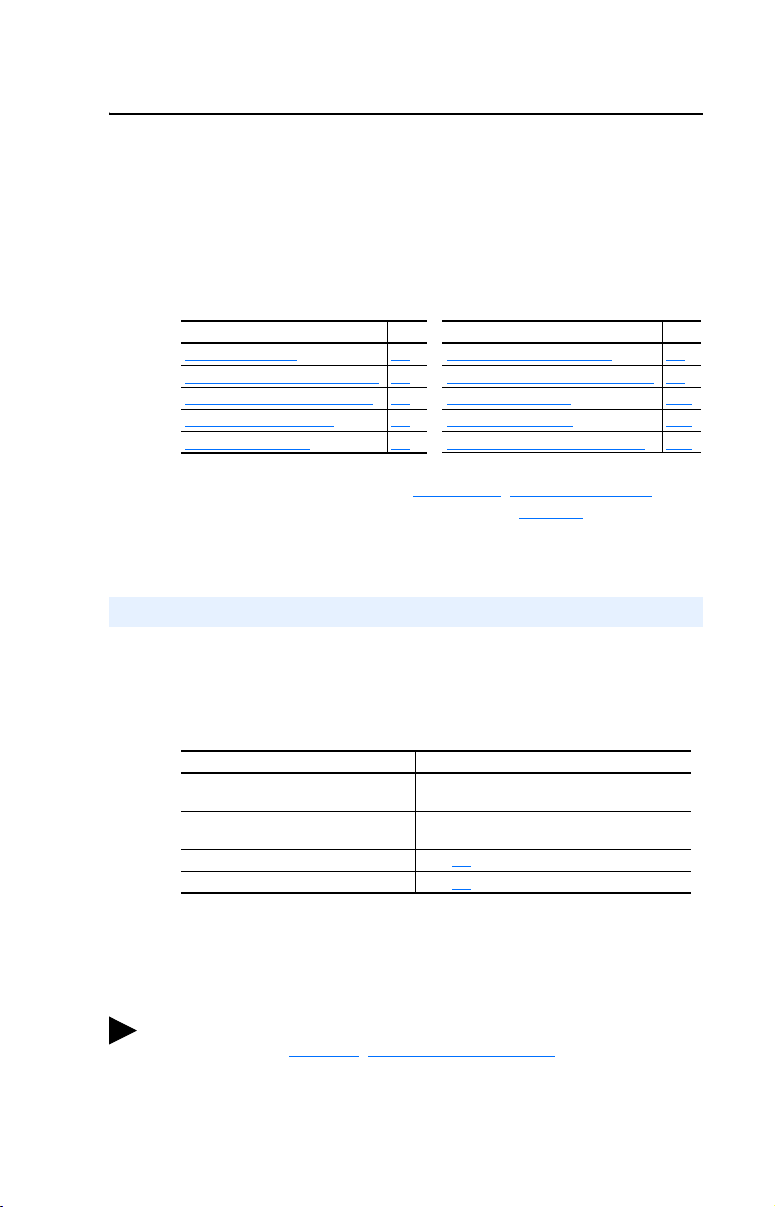
Related Documentation
For: Refer to: Publication
DeviceNet™ Cables
and Components
DeviceNet Network
Installation
DeviceNet Networks DeviceNet Starter Kit DN-6.5.16
DriveExplorer™ DriveExplorer Getting Results Manual
DriveTools 2000™ DriveTools 2000 Online Help –
HIM HIM Quick Reference 22HIM-QR001…
Logix 5550 ControlLogix DeviceNet Scanner Installation Instructions 1756-5.66
PowerFlex™ 4
Drive
PowerFlex™ 40
Drive
RSLinx™ Getting Results with RSLinx
RSLogix™ 5 RSLogix 5 Getting Results Guide
RSLogix 500 RSLogix 500 Getting Results Guide
RSLogix 5000 RSLogix 5000 Getting Results Guide
RSNetWorx™ for
DeviceNet
SLC 500™ and
1747-SDN
PLC-5™ and
1771-SDN
DeviceNet Product Overview DN-2.5
DeviceNet Cable System Planning and Installation
Manual
Online help (installed with the software)
PowerFlex 4 User Manual
PowerFlex 4 Quick Start
PowerFlex 40 User Manual
PowerFlex 40 Quick Start
Online help (installed with the software)
Online help (installed with the software)
Online help (installed with the software)
Online help (installed with the software)
RSNetWorx for DeviceNet Getting Results Guide
Online help (installed with the software)
DeviceNet Scanner Module Installation Instructions
DeviceNet Scanner Module Configuration Manual
DeviceNet Scanner Module Installation Instructions
DeviceNet Scanner Module Configuration Manual
DN-6.7.2
9306-5.2
22A-UM001…
22A-QS001…
22B-UM001…
22B-QS001…
9399-WAB32GR
9399-RL53GR
9399-RL50GR
9399-RLD300GR
9398-DNETGR
1747-5.8
1747-6.5.2
1747-5.14
1771-6.5.118
Documentation can be obtained online at http://www.ab.com/manuals.

P-2 About This Manual
Conventions Used in this Manual
The following conventions are used throughout this manual:
• Parameter names are shown in the following format Parameter
xx - [*]. The xx represents the parameter number. The * represents
the parameter name. For example Parameter 01 - [Mode].
• Menu commands are shown in bold type face and follow the format
Menu > Command. For example, if you read “Select File > Open,”
you should click the File menu and then click the Open command.
• RSNetWorx for DeviceNet (version 4.01), RSLinx (version 2.40),
and RSLogix5000 (version 11) were used for the screen shots in this
manual. Different versions of the software may differ in appearance
and procedures.
• The firmware release is displayed as FRN X.xxx. The “FRN”
signifies Firmware Release Number. The “X” is the major release
number. The “xxx” is the minor update number. This manual is for
Firmware release 1.xxx.
• This manual provides information about the DeviceNet adapter and
using it with PowerFlex 40 drives. The adapter can be used with other
products that support an internal DSI adapter. Refer to the
documentation for your product for specific information about how it
works with the adapter.
Rockwell Automation Support
Rockwell Automation, Inc. offers support services worldwide, with over
75 sales/support offices, over 500 authorized distributors, and over 250
authorized systems integrators located through the United States alone.
In addition, Rockwell Automation, Inc. representatives are in every
major country in the world.
Local Product Support
Contact your local Rockwell Automation, Inc. representative for sales
and order support, product technical training, warranty support, and
support service agreements.
Technical Product Assistance
If you need to contact Rockwell Automation, Inc. for technical assistance,
please review the information in Chapter 8
still have problems, then call your local Rockwell Automation, Inc.
representative.
, Troubleshooting first. If you
Chapter 1
Getting Started
The 22-COMM-D DeviceNet adapter is a communication option
intended for installation into a PowerFlex 40 drive. It can also be used
with other Allen-Bradley products that support an internal DSI adapter.
The Multi-Drive feature (Chapter
PowerFlex 4 drives and other DSI Hosts to connect to DeviceNet.
Topic Page Topi c Page
Components 1-1 Safety Precautions 1-4
Features 1-2 Quick Start 1-5
Compatible Products 1-3 Modes of Operation 1-6
Required Equipment 1-3
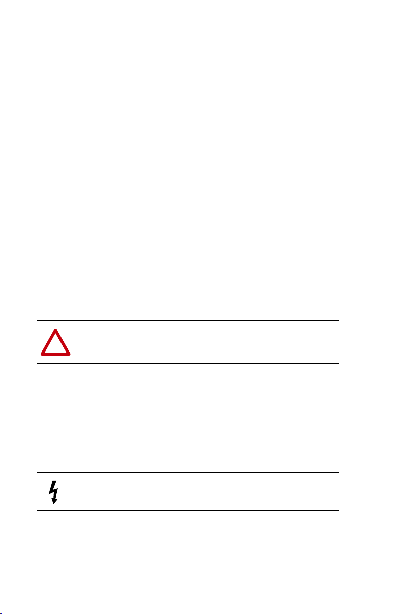
Components
Figure 1.1 Components of the Adapter
➊
7) also provides a means for
➋
➎
➍
➌
Item Part Description
Status
➊
Indicators
DSI Connector A 20-pin, single-row shrouded male header. An Internal
➋
DeviceNet
➌
Connector
Node Address/
➍
Rate Switches
Mode Jumper
➎
(J2)
Three LEDs that indicate the status of the connected drive,
adapter, and network. Refer to Chapter 8, Troubleshooting.
Interface cable is connected to this connector and a connector
on the drive.
A 5-pin connector to which a 5-pin linear plug can be connected.
Switches for setting the node address and network data rate.
Refer to Chapter 2
Selects Single or Multi-Drive mode of operation. Refer to
Chapter 2
, Installing the Adapter.
, Installing the Adapter.

1-2 Getting Started
Features
The DeviceNet adapter features the following:
• The adapter is mounted in the PowerFlex 40 drive. It receives the
required power from the drive and from the DeviceNet network.
• Switches let you set a node address and network data rate before
applying power to the PowerFlex drive. Alternately, you can disable
the switches and use parameters to configure these functions.
• A jumper lets you select between Single or Multi-Drive mode of
operation. In Single mode, the adapter represents a single drive on
one node. In Multi-Drive mode, the adapter represents up to 5 drives
on one node.
• A number of configuration tools can be used to configure the adapter
and connected drive. The tools include an external PowerFlex
4-Class HIM (22-HIM-*), network software such as RSNetWorx for
DeviceNet, or drive-configuration software such as DriveExplorer
(version 3.01 or higher) or DriveTools 2000 (version 1.01 or higher).
• Status indicators report the status of the drive communications,
adapter, and network.
• I/O, including Logic Command/Reference, may be configured for
your application using a parameter.
• Explicit and UCMM (Unconnected Message Manager) Messages are
supported.
• Multiple data exchange methods, including Polled, Cyclic, and
Change of State (COS), can be used to transmit data between the
network and adapter.
• User-defined fault actions determine how the adapter and PowerFlex
drive respond to communication disruptions on the network and
controllers in idle mode.
• Faulted node recovery is supported. You can configure a device even
when it is faulted on the network if you have a configuration tool that
uses faulted node recovery and have properly set the adapter node
address switches and data rate switches.

Getting Started 1-3
Compatible Products
The DeviceNet adapter is compatible with Allen-Bradley PowerFlex
drives and other products that support an internal DSI adapter. At the
time of publication, compatible products include:
• PowerFlex 40 drives
The Multi-Drive feature (Chapter 7) also provides a means for
PowerFlex 4 drives and other DSI Hosts to connect to DeviceNet.
Required Equipment
Equipment Shipped with the Adapter
When you unpack the adapter, verify that the package includes:
❑ One DeviceNet adapter
❑ One five-pin linear DeviceNet plug
(connected to the DeviceNet connector on the adapter)
❑ A 15.24 cm (6 in.) Internal Interface Cable
❑ One grounding wrist strap
❑ This manual
User-Supplied Equipment
To install and configure the DeviceNet adapter, you must supply:
❑ A small flathead screwdriver
❑ DeviceNet cable
– Thin cable with an outside diameter of 6.9 mm (0.27 in.) is
recommended
❑ Configuration tool, such as:
– PowerFlex 4-Class HIM (22-HIM-*)
– DriveExplorer (version 3.01 or higher)
– DriveTools 2000 (version 1.01 or higher)
– RSNetWorx for DeviceNet
– Serial Converter (22-SCM-232)
❑ Computer with a DeviceNet communications adapter installed
(Examples: 1784-PCD, 1784-PCID, 1784-PCIDS, or 1770-KFD)
❑ Controller configuration software
(Examples: RSLogix5, RSLogix500, or RSLogix 5000)
1-4 Getting Started
Safety Precautions
Please read the following safety precautions carefully:
ATTENTION: Risk of injury or death exists. The PowerFlex drive
may contain high voltages that can cause injury or death. Remove all
!
power from the PowerFlex drive, and then verify power has been
removed before installing or removing an adapter.
ATTENTION: Risk of injury or equipment damage exists. Only
personnel familiar with drive and power products and the associated
!
machinery should plan or implement the installation, start-up,
configuration, and subsequent maintenance of the product using a
DeviceNet adapter. Failure to comply may result in injury and/or
equipment damage.
ATTENTION: Risk of injury or equipment damage exists. If the
DeviceNet adapter is transmitting control I/O to the drive, the drive may
!
fault when you reset the adapter. Determine how your drive will
respond before resetting an adapter.
ATTENTION: Risk of injury or equipment damage exists.
Parameters 7 - [Comm Flt Action] and 8 - [Idle Flt Action] let you
!
determine the action of the adapter and connected PowerFlex drive if
communications are disrupted. By default, these parameters fault the
PowerFlex drive. You can set these parameters so that the PowerFlex
drive continues to run. Precautions should be taken to ensure that the
settings of these parameters do not create a hazard of injury or
equipment damage.
ATTENTION: Hazard of injury or equipment damage exists. When a
system is configured for the first time, there may be unintended or
!
incorrect machine motion. Disconnect the motor from the machine or
process during initial system testing.
ATTENTION: Hazard of injury or equipment damage exists. The
examples in this publication are intended solely for purposes of
!
example. There are many variables and requirements with any
application. Rockwell Automation, Inc. does not assume responsibility
or liability (to include intellectual property liability) for actual use of
the examples shown in this publication.

Getting Started 1-5
Quick Start
This section is designed to help experienced users start using the
DeviceNet adapter. If you are unsure how to complete a step, refer to the
referenced chapter.
Step Refer to
1 Review the safety precautions for the adapter. Throughout This
2 Verify that the PowerFlex drive is properly installed. Drive User
3 Commission the adapter.
Set a unique node address and the appropriate data rate using
the switches on the adapter. If desired, you can disable the
switches and use parameter settings instead.
4 Install the adapter.
Verify that the PowerFlex drive and DeviceNet network are not
powered. Then, connect the adapter to the network using a
DeviceNet cable and to the drive using the Internal Interface
cable. Use the captive screws to secure and ground the adapter
to the drive.
5 Apply power to the adapter.
The adapter receives power from the drive and network. Apply
power to the network and to the drive. The status indicators
should be green. If they flash red, there is a problem. Refer to
Chapter
8, Troubleshooting.
6 Configure the adapter for your application.
Set the following parameters for the adapter as required by your
application:
• Node address and data rate.
• I/O configuration.
• Change of State, Cyclic, or polled I/O data exchange.
• Fault actions.
7 Apply power to the DeviceNet master and other devices on
the network.
Verify that the master and network are installed and functioning in
accordance with DeviceNet standards, and then apply power to
them.
8 Configure the scanner to communicate with the adapter.
Use a network tool such as RSNetWorx for DeviceNet to
configure the scanner on the network. Make sure to:
• Set up the scan list.
• Map the adapter data to the scan list.
• Save your DeviceNet configuration to the scanner and a file.
9 Create a ladder logic program.
Use a programming tool such as RSLogix to create a ladder logic
program that enables you to do the following:
• Control the adapter and connected drive.
• Monitor or configure the drive using Explicit Messages.
Manual
Manual
Chapter 2,
Installing the
Adapter
Chapter 3,
Configuring the
Adapter
DeviceNet
Cable System
Planning and
Installation
Manual
Chapter 4,
Configuring the
Scanner
Chapter 5,
Using I/O
Messaging
Chapter 6,
Using Explicit
Messaging
1-6 Getting Started
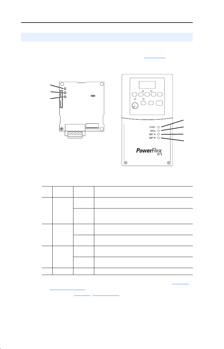
Modes of Operation
The adapter uses three status indicators to report its operating status.
They can be viewed through the drive cover. See Figure 1.2
Figure 1.2 Status Indicators (location on drive may vary)
➊
➋
➌
.
➊
➋
➌
➍
Item Status
Indicator
PORT Green Normal Operation. The adapter is properly connected and
➊
MOD Green Normal Operation. The adapter is operational and is
➋
NET A Green Normal Operation. The adapter is properly connected and
➌
NET B Off Not used for DeviceNet.
➍
(1)
If all status indicators are off, the adapter is not receiving power. Refer to Chapter 2,
Installing the Adapter
occur, refer to Chapter
(1)
Status
Flashing
Green
Flashing
Green
Flashing
Green
Description
is communicating with the drive.
The adapter is in the process of establishing a connection
to the drive. This status indicator will turn solid green or
red.
transferring I/O data.
Normal Operation. The adapter is operational but is not
transferring I/O data.
communicating on the network.
The adapter is properly connected but is not
communicating with any devices on the network.
, for instructions on installing the adapter. If any other conditions
8, Troubleshooting.

Chapter 2
Installing the Adapter
Chapter 2 provides instructions for installing the adapter in a
PowerFlex 40 drive.
Topic Page
Preparing for an Installation 2-1
Commissioning the Adapter 2-1
Connecting the Adapter to the Network 2-4
Connecting the Adapter to the Drive 2-5
Applying Power 2-7
Preparing for an Installation
Before installing the DeviceNet adapter:
• Read the DeviceNet Product Overview Manual, Publication DN-2.5,
and the DeviceNet Cable System Planning and Installation Manual,
Publication DN-6.7.2. These manuals will provide information on
selecting cables, setting up a network, and network basics.
• Verify that you have all required equipment. Refer to Chapter 1,
Getting Started
.
Commissioning the Adapter
To commission the adapter, you must set a unique node address and the
data rate that is used by the network. (Refer to the Glossary
about data rates and node addresses.)
Important: New settings are recognized only when power is applied to
the adapter. If you change a setting, cycle power.
ATTENTION: Risk of equipment damage exists. The DeviceNet
adapter contains ESD (Electrostatic Discharge) sensitive parts that can
!
be damaged if you do not follow ESD control procedures. Static control
precautions are required when handling the adapter. If you are
unfamiliar with static control procedures, refer to Guarding Against
Electrostatic Damage, Publication 8000-4.5.2.
for details
2-2 Installing the Adapter
J2
J2
p
n
e
n
8
3
5
6
E
U
1
8
3
5
6
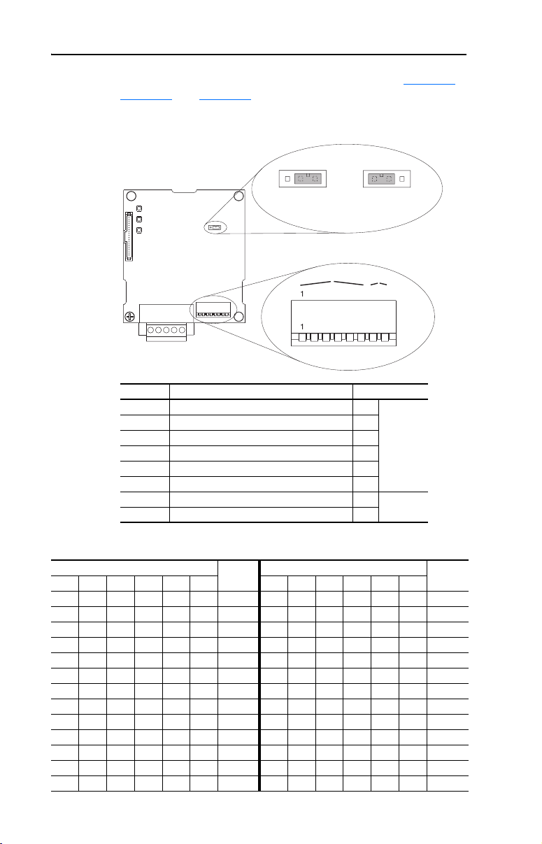
1. Set the adapter node address and data rate switches (see Figure 2.1,
Figure 2.2, and Figure 2.3).
Figure 2.1 Setting Node Address/Data Rate Switches and Single/Multi-Drive
Operation Jumper
Single Drive
eratio
O
NOD
P = OPEN =
Multi-Driv
Operatio
Switches Description Default
SW 1 Least Significant Bit (LSB) of Node Address 1
SW 2 Bit 1 of Node Address 1
SW 3 Bit 2 of Node Address 1
SW 4 Bit 3 of Node Address 1
Node 63
SW 5 Bit 4 of Node Address 1
SW 6 Most Significant Bit (MSB) of Node Address 1
SW 7 Least Significant Bit (LSB) of Data Rate 1
SW 8 Most Significant Bit (MSB) of Data Rate 1
Autobaud
Figure 2.2 Node Address Switch Settings (UP = OPEN = 1)
Switch Setting Node Switch Setting Node
SW 1 SW 2 SW 3 SW 4 SW 5 SW 6 Address SW 1 SW 2 SW 3 SW 4 SW 5 SW 6 Address
0 0 0 0 0 0 0 1 0 1 1 0 0 13
1 0 0 0 0 0 1 0 1 1 1 0 0 14
0 1 0 0 0 0 2 1 1 1 1 0 0 15
1 1 0 0 0 0 3 0 0 0 0 1 0 16
0 0 1 0 0 0 4 1 0 0 0 1 0 17
1 0 1 0 0 0 5 0 1 0 0 1 0 18
0 1 1 0 0 0 6 1 1 0 0 1 0 19
1 1 1 0 0 0 7 0 0 1 0 1 0 20
0 0 0 1 0 0 8 1 0 1 0 1 0 21
1 0 0 1 0 0 9 0 1 1 0 1 0 22
0 1 0 1 0 0 10 1 1 1 0 1 0 23
1 1 0 1 0 0 11 0 0 0 1 1 0 24
0 0 1 1 0 0 12 1 0 0 1 1 0 25

Installing the Adapter 2-3
Figure 2.2 Node Address Switch Settings (UP = OPEN = 1) (Continued)
Switch Setting Node Switch Setting Node
SW 1 SW 2 SW 3 SW 4 SW 5 SW 6 Address SW 1 SW 2 SW 3 SW 4 SW 5 SW 6 Address
0 1 0 1 1 0 26 1 0 1 1 0 1 45
1 1 0 1 1 0 27 0 1 1 1 0 1 46
0 0 1 1 1 0 28 1 1 1 1 0 1 47
1 0 1 1 1 0 29 0 0 0 0 1 1 48
0 1 1 1 1 0 30 1 0 0 0 1 1 49
1 1 1 1 1 0 31 0 1 0 0 1 1 50
0 0 0 0 0 1 32 1 1 0 0 1 1 51
1 0 0 0 0 1 33 0 0 1 0 1 1 52
0 1 0 0 0 1 34 1 0 1 0 1 1 53
1 1 0 0 0 1 35 0 1 1 0 1 1 54
0 0 1 0 0 1 36 1 1 1 0 1 1 55
1 0 1 0 0 1 37 0 0 0 1 1 1 56
0 1 1 0 0 1 38 1 0 0 1 1 1 57
1 1 1 0 0 1 39 0 1 0 1 1 1 58
0 0 0 1 0 1 40 1 1 0 1 1 1 59
1 0 0 1 0 1 41 0 0 1 1 1 1 60
0 1 0 1 0 1 42 1 0 1 1 1 1 61
1 1 0 1 0 1 43 0 1 1 1 1 1 62
0 0 1 1 0 1 44 1 1 1 1 1 1 63
Figure 2.3 Data Rate Switch Settings (UP = OPEN = 1)
Switch Setting Data
SW 7 SW 8 Rate
0 0 125 kbps
1 0 250 kbps
0 1 500 kbps
1 1 Autobaud
If all switches are in the CLOSED position (all 0’s), then the Node
Address and Data Rate are determined by parameter settings
(Parameter 02 - [DN Addr Cfg] and Parameter 04 - [DN Rate Cfg]).
2. Set the adapter mode jumper for Single or Multi-Drive operation (see
Figure 2.1
Jumper Setting Description
Right position or
jumper missing
Left position Sets the adapter for Multi-Drive operation mode using up to 5
and these setting descriptions).
Sets the adapter for Single drive mode (default setting) using a
single drive connection.
Important: In this mode, connections to multiple drives
must be removed since all powered and connected hosts
will respond to any message sent by the adapter.
different drives. DSI peripherals do not operate with the adapter in
this mode.
2-4 Installing the Adapter
Connecting the Adapter to the Network
ATTENTION: Risk of injury or death exists. The PowerFlex drive
may contain high voltages that can cause injury or death. Remove all
!
power from the PowerFlex drive, and then verify power has been
removed before installing or removing an adapter.
1. Remove power from the drive.
2. Use static control precautions.
3. Remove the drive cover.
4. Connect a DeviceNet cable to the network, and route it through the
bottom of the PowerFlex drive. DeviceNet Thin cable with an outside
diameter of 6.9 mm (0.27 in.) is recommended. (See Figure 2.6
Important: Maximum cable length depends on data rate. Refer to
the Glossary
5. Connect a 5-pin linear plug to the DeviceNet cable.
A 10-pin linear plug is not supported. A 5-pin linear plug is shipped
with the adapter.
.)
, Data Rate.
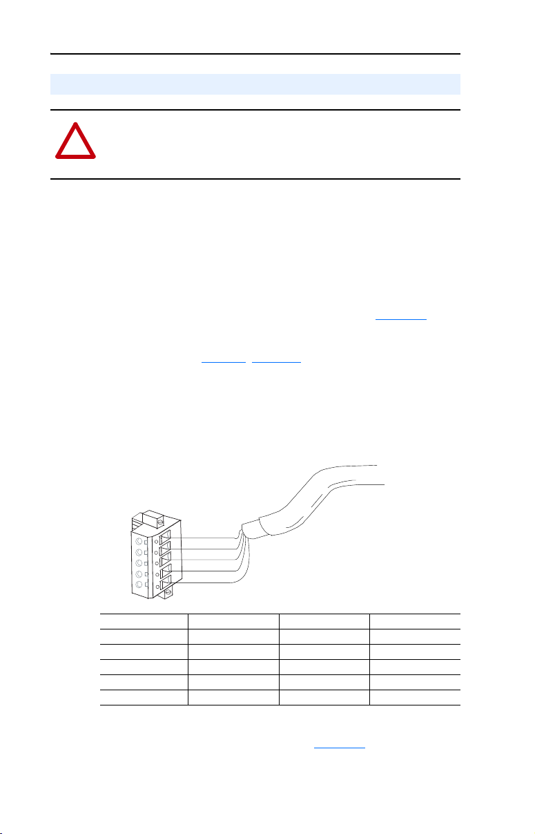
Figure 2.4 Connecting a 5-Pin Linear Plug to the Cable
5
4
3
2
1
Terminal Color Signal Function
5 Red V+ Powe r Supp ly
4 White CAN_H Signal High
3 Bare SHIELD Shield
2 Blue CAN_L Signal Low
1 Black V– Common
Red
White
Bare
Blue
Black
6. Insert the DeviceNet cable plug into the mating adapter receptacle,
and secure it with the two screws. (See Figure 2.5
, item 2.) Verify
that the colors of the wires on the plug match up with the color codes
on the receptacle.
Installing the Adapter 2-5
Connecting the Adapter to the Drive
1. Remove power from the drive.
2. Use static control precautions.
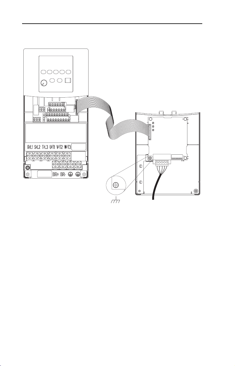
3. Mount the adapter on the cover, using the screw on the adapter to
secure it in place.
Important: Tighten the screw in the lower left hole to ground the
adapter (see Figure 2.6).
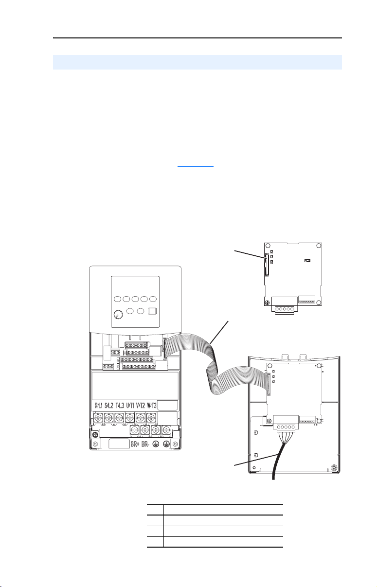
4. Connect the Internal Interface cable to the DSI port on the drive and
then to the mating DSI connector on the adapter.
Figure 2.5 DSI Ports and Internal Interface Cables
DeviceNet Adapter
➊
PowerFlex 40 Drive
B and C Frames
(cover removed)
# Description
➊ DSI Connector
➋ 15.24 cm (6 in.) Internal Interface cable
➌ DeviceNet cable
➋
➌
Back of Cover
2-6 Installing the Adapter
Figure 2.6 Mounting the Adapter
PowerFlex 40 Drive
B and C Frames
(cover removed)
Adapter Mounted
on Back of Cover

Installing the Adapter 2-7
Applying Power
ATTENTION: Risk of equipment damage, injury, or death exists.
Unpredictable operation may occur if you fail to verify that parameter
!
settings and switch settings are compatible with your application.
Verify that settings are compatible with your application before
applying power to the drive.
1. Reinstall the cover on the drive. The status indicators can be viewed
on the front of the drive after power has been applied.
2. Ensure that the adapter will have a unique address on the network
and is set at the correct data rate or to autobaud. If a new data rate or
address is needed, reset its switches (refer to Commissioning the
Adapter in this chapter).
3. Apply power to the PowerFlex drive. The adapter receives its power
from the connected drive and network. When you apply power to the
product and network for the first time, the status indicators should be
green after an initialization. If the status indicators go red, there is a
problem. Refer to Chapter
4. If the software settings for the data rate and node address are to be
used, a configuration tool such as DriveExplorer can be used to
adjust the respective parameters in the adapter.
8, Troubleshooting.

2-8 Installing the Adapter
Notes:
Chapter 3
Configuring the Adapter
Chapter 3 provides instructions and information for setting the
parameters in the adapter.
Topic Page To pic Page
Configuration Tools 3-1 Setting the I/O Configuration 3-8
Using the PowerFlex 4-Class HIM 3-2 Selecting COS, Cyclic, or Polled I/O 3-8
Using RSNetWorx for DeviceNet 3-3 Setting a Fault Action 3-10
Setting the Node Address 3-7 Resetting the Adapter 3-11
Setting the Data Rate 3-7 Viewing the Adapter Configuration 3-12
For a list of parameters, refer to Appendix B, Adapter Parameters. For
definitions of terms in this chapter, refer to the Glossary
Configuration Tools
The DeviceNet adapter stores parameters and other information in its
own non-volatile memory. You must, therefore, access the adapter to
view and edit its parameters. The following tools can be used to access
the adapter parameters:
.
Tool Refer To:
DriveExplorer Software
(version 3.01 or higher)
DriveTools 2000 Software
(version 1.01 or higher)
PowerFlex 4-Class HIM (22-HIM-*) page 3-2
RSNetWorx for DeviceNet Software page 3-3
RSNetWorx for DeviceNet (version 4.01) and RSLinx (version 2.40)
were used for examples in this manual. Different versions of software
may differ in appearance and procedures.
TIP: Explicit Messaging can also be used to configure an adapter and
drive. Refer to Chapter
6, Using Explicit Messaging.
DriveExplorer Getting Results Manual,
Publication 9306-5.3, or the online help
DriveTools 2000 Online Help
3-2 Configuring the Adapter
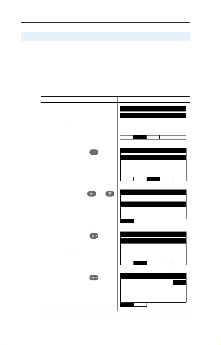
Using the PowerFlex 4-Class HIM
The PowerFlex 4-Class HIM (Human Interface Module) can be used to
access parameters in the adapter (see basic steps shown below). It is
recommended that you read through the steps for your HIM before
performing the sequence. For additional HIM information, refer to your
HIM Quick Reference card.
Using the HIM
Step Key(s) Example Screens
1. Power up the drive.
Then plug the HIM
into the drive. The
Parameters menu
for the drive
displayed.
will be
Parameters
Groups
Linear List
Changed Params
DIAG PA RA M DSEL MEM SEL !
2. Press Sel key once
to display the
Device Select
menu.
3. Press Enter to
display the DSI
Devices menu.
Press Down Arrow
to scroll to
22-COMM-D.
4. Press Enter to select
the DeviceNet
adapter. The
Parameters menu
for the adapter
be displayed.
5. Press Enter to
access the
parameters. Edit the
adapter parameters
using the same
techniques that you
use to edit drive
parameters.
will
Sel
and
Device Selected
DSI Devices
DIAG PARAM DSEL MEM SEL !
DSI Devices
Powe rFl ex 4 0
22-COMM-D
Parameters
Linear List
Changed Params
DIAG PA RA M DSEL MEM SEL !
Mode RO
Parameter: #
Single Drive 0
VAL UE LIMITS SEL !
001
Configuring the Adapter 3-3
Using RSNetWorx for DeviceNet
RSNetWorx for DeviceNet is a Rockwell Software application that can
be used to set up DeviceNet networks and configure connected devices.
To set up RSLinx for RSNetWorx for DeviceNet
To use RSNetWorx for DeviceNet, you must first set up a driver in
RSLinx. The driver provides a communications link between the
computer and DeviceNet network.
Step Icons
1. Start RSLinx, and select Communications > Configure
Drivers to display the Configure Drivers dialog box.
2. In the Available Driver Types box, select DeviceNet
Drivers, and then click Add New. The DeviceNet Driver
Selection dialog box appears.
3. In the Available DeviceNet Drivers list, select the adapter
connected to your computer, and then click Select. A Driver
Configuration dialog box appears.
4. Configure the driver for your computer and network
settings, and then click OK. The Configure Drivers dialog
box reports the progress of the configuration. Then, the
Add New RSLinx Driver dialog box appears.
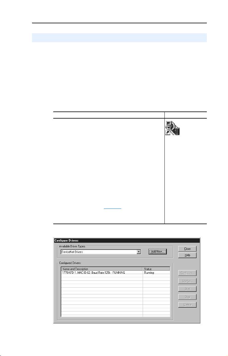
5. Type a name (if desired), and then click OK. The Configure
Drivers dialog box reappears, and the new driver is in the
Configured Drivers List (Figure 3.1
6. Click Close to close the dialog box. Leave RSLinx running.
).
Shortcut to
RSLinx
Figure 3.1 Configure Drivers Dialog Box with a Configured Driver
3-4 Configuring the Adapter
To go online with RSNetWorx for DeviceNet
You can view the devices on a DeviceNet network by going online. A
device may appear as an unrecognized device if RSNetWorx for
DeviceNet does not have an EDS file for it.
Step Icons
1. After setting up a driver in RSLinx, start RSNetWorx for
DeviceNet.
2. Select Network > Online. If the Browse for Network dialog
box appears, RSLinx has multiple drivers configured.
Select your DeviceNet network, and click OK. A prompt
appears.
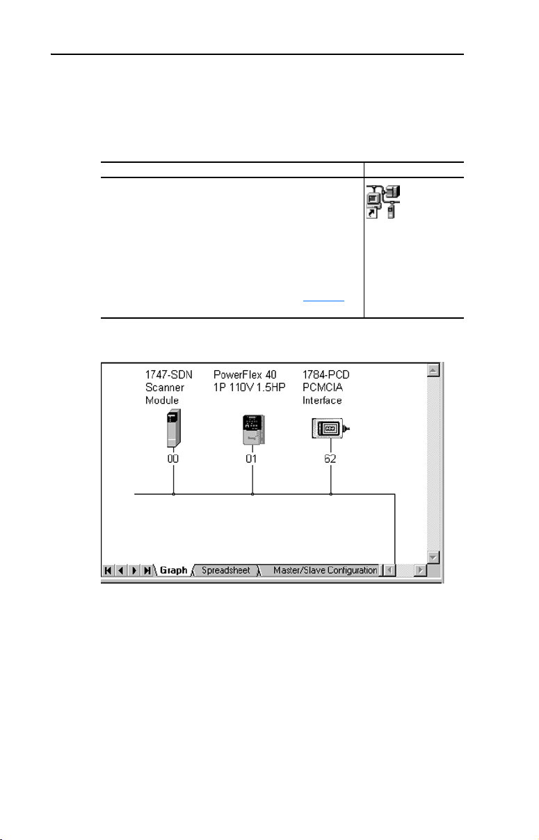
3. RSNetWorx browses the network and any devices on the
network appear in the Configuration View. You can select
Graph, Spreadsheet, or Master/Slave views. Figure 3.2
shows an example network in a Graph view.
Figure 3.2 Example DeviceNet Network
Shortcut to
RSNetWorx
Configuring the Adapter 3-5
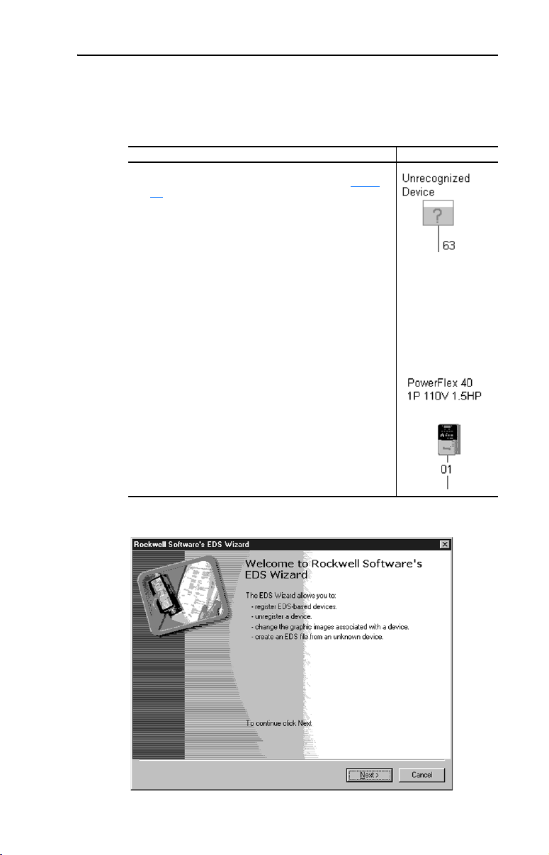
To create an EDS file
If the adapter and drive appear as an unrecognized device, create an EDS
file for it.
Step Icons
1. Right-click the “Unrecognized Device” icon, and select
Register Device in the menu. The EDS Wizard (Figure
3.3) appears.
2. Click Next to display the next step.
3. Select Upload EDS, and then click Next.
4. Type a description (if desired), and then click Next.
5. Under Polled, select Enabled, type 4 in the Input Size and
Output Size boxes, and then click Next. RSNetWorx will
upload the EDS file from the drive and adapter.
6. Click Next to display the icon options for the node. We
recommend that you use the icon for your product. You can
change icons by clicking Change icon.
7. Click Next to view a summary, and then click Next again to
accept it.
8. Click Finish to finish the EDS creation. A new icon
represents the PowerFlex drive and adapter in the
Configuration View.
Figure 3.3 EDS Wizard
3-6 Configuring the Adapter
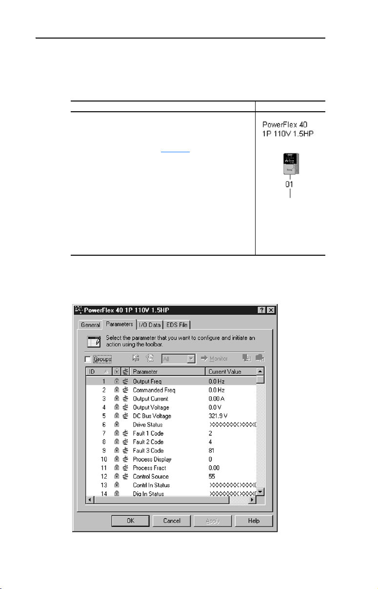
To access and edit parameters
Parameters in the drive and adapter can be edited with RSNetWorx. The
adapter parameters are appended to the list of drive parameters.
Step Icons
1. After creating an EDS file, right-click on the icon for the
PowerFlex drive and adapter and select Properties. The
PowerFlex Drive dialog box appears.
2. Click the Parameters tab (Figure 3.4). If an EDS Editor
message appears, click Upload to load the parameter
values in the drive to the computer.
Parameters are displayed in numerical order. You can
either scroll through the list or select a specific group of
parameters in the Groups box. The available groups and
the numbers of the adapter parameters will vary based on
the type of drive that is connected to the adapter.
3. In the Current Value column, double-click a value to edit it.
4. Click Apply to save changes to the device.
Figure 3.4 Example PowerFlex Drive Dialog Box
Loading...