


SafeZone Mini
Safety Laser Scanner
User Manual
R
Important User Information
Because of the variety of uses for the products described in this publication, those responsible for the application and use of this control equipment must satisfy themselves that all necessary steps have been taken to assure that each application and use meets all performance and safety requirements, including any applicable laws, regulations, codes and standards.
The illustrations, charts, sample programs and layout examples shown in the guide are intended solely for purposes of example. Since there are many variables and requirements associated with any particular installation, Rockwell Automation does not assume responsibility or liability (to include intellectual property liability) for actual use based upon the examples shown in this publication.
Rockwell Automation publication SGI-1.1, Safety Guidelines for the Application, Installation and Maintenance of Solid-State Control (available from your local Rockwell Automation sales office), describes some important differences between solid-state equipment and electromechanical devices that should be taken into consideration when applying products such as those described in this publication.
Reproduction of the contents of this copyrighted publication, in whole or part, without written permission of Rockwell Automation, is prohibited.
Throughout this manual we use notes to make you aware of safety considerations:
|
WARNING |
|
Identifies information about practices or circumstances that can cause an explosion in |
||
|
|
|
|
|
a hazardous environment, which may lead to personal injury or death, property |
|
|
|
|
||
|
|
|
|
|
damage, or economic loss. |
|
|
|
|
|
|
|
|
|
|
|
|
|
|
|
|
|
|
|
|
|
|
|
Identifies information that is critical for successful application and understanding of |
|
IMPORTANT |
|
|||
|
|
the product. |
|||
|
|
|
|
|
|
ATTENTION Identifies information about practices or circumstances that can lead to personal  injury or death, property damage, or economic loss. Attentions help you identify a hazard, avoid a hazard, and recognize the consequences.
SHOCK HAZARD Labels may be on or inside the equipment (for example, drive or motor) to alert people that dangerous voltage may be present.
BURN HAZARD Labels may be on or inside the equipment (for example, drive or motor) to alert people that surfaces may reach dangerous temperatures.
It is recommended that you save this user manual for future use.

Contents
Contents
About this document. . . . . . . . . . . . . . . . . . . . . . . . . . . . . . . . . . . . . . . . . . . . . . . . . . . Chapter 1
Function of this document . . . . . . . . . . . . . . . . . . . . . . . . . . . . . . . . . . . . . . . . . . . . . . . . . . . . . . . . . . . . . . . . . . . . . . . . . . . . . . . 4 Target group . . . . . . . . . . . . . . . . . . . . . . . . . . . . . . . . . . . . . . . . . . . . . . . . . . . . . . . . . . . . . . . . . . . . . . . . . . . . . . . . . . . . . . . . . . . 4 Scope . . . . . . . . . . . . . . . . . . . . . . . . . . . . . . . . . . . . . . . . . . . . . . . . . . . . . . . . . . . . . . . . . . . . . . . . . . . . . . . . . . . . . . . . . . . . . . . . . 4 Depth of information . . . . . . . . . . . . . . . . . . . . . . . . . . . . . . . . . . . . . . . . . . . . . . . . . . . . . . . . . . . . . . . . . . . . . . . . . . . . . . . . . . . . 4 Abbreviations used . . . . . . . . . . . . . . . . . . . . . . . . . . . . . . . . . . . . . . . . . . . . . . . . . . . . . . . . . . . . . . . . . . . . . . . . . . . . . . . . . . . . . 4 Symbols used . . . . . . . . . . . . . . . . . . . . . . . . . . . . . . . . . . . . . . . . . . . . . . . . . . . . . . . . . . . . . . . . . . . . . . . . . . . . . . . . . . . . . . . . . . 5
On safety . . . . . . . . . . . . . . . . . . . . . . . . . . . . . . . . . . . . . . . . . . . . . . . . . . . . . . . . . . . . . Chapter 2
Qualified safety personnel . . . . . . . . . . . . . . . . . . . . . . . . . . . . . . . . . . . . . . . . . . . . . . . . . . . . . . . . . . . . . . . . . . . . . . . . . . . . . . . 6 Applications of the device . . . . . . . . . . . . . . . . . . . . . . . . . . . . . . . . . . . . . . . . . . . . . . . . . . . . . . . . . . . . . . . . . . . . . . . . . . . . . . . . 6 Correct use. . . . . . . . . . . . . . . . . . . . . . . . . . . . . . . . . . . . . . . . . . . . . . . . . . . . . . . . . . . . . . . . . . . . . . . . . . . . . . . . . . . . . . . . . . . . . 6 General safety notes and protective measures. . . . . . . . . . . . . . . . . . . . . . . . . . . . . . . . . . . . . . . . . . . . . . . . . . . . . . . . . . . . . . . 7 Environmental protection . . . . . . . . . . . . . . . . . . . . . . . . . . . . . . . . . . . . . . . . . . . . . . . . . . . . . . . . . . . . . . . . . . . . . . . . . . . . . . . . 7
Disposal . . . . . . . . . . . . . . . . . . . . . . . . . . . . . . . . . . . . . . . . . . . . . . . . . . . . . . . . . . . . . . . . . . . . . . . . . . . . . . . . . . . . . . . . . . 8 Separation of materials . . . . . . . . . . . . . . . . . . . . . . . . . . . . . . . . . . . . . . . . . . . . . . . . . . . . . . . . . . . . . . . . . . . . . . . . . . . . . 8 Applicable directives and standards . . . . . . . . . . . . . . . . . . . . . . . . . . . . . . . . . . . . . . . . . . . . . . . . . . . . . . . . . . . . . . . . . . . . . . . 8
Product description . . . . . . . . . . . . . . . . . . . . . . . . . . . . . . . . . . . . . . . . . . . . . . . . . . . . Chapter 3
Special features . . . . . . . . . . . . . . . . . . . . . . . . . . . . . . . . . . . . . . . . . . . . . . . . . . . . . . . . . . . . . . . . . . . . . . . . . . . . . . . . . . . . . . . 10 Function. . . . . . . . . . . . . . . . . . . . . . . . . . . . . . . . . . . . . . . . . . . . . . . . . . . . . . . . . . . . . . . . . . . . . . . . . . . . . . . . . . . . . . . . . . . . . . 10 Principle of operation . . . . . . . . . . . . . . . . . . . . . . . . . . . . . . . . . . . . . . . . . . . . . . . . . . . . . . . . . . . . . . . . . . . . . . . . . . . . . . 10 Field set comprising of protective field and warning field(s) . . . . . . . . . . . . . . . . . . . . . . . . . . . . . . . . . . . . . . . . . . . . . 11 SafeZone Mini. . . . . . . . . . . . . . . . . . . . . . . . . . . . . . . . . . . . . . . . . . . . . . . . . . . . . . . . . . . . . . . . . . . . . . . . . . . . . . . . . . . . . . . . . 12 Device components. . . . . . . . . . . . . . . . . . . . . . . . . . . . . . . . . . . . . . . . . . . . . . . . . . . . . . . . . . . . . . . . . . . . . . . . . . . . . . . . 12 Applications . . . . . . . . . . . . . . . . . . . . . . . . . . . . . . . . . . . . . . . . . . . . . . . . . . . . . . . . . . . . . . . . . . . . . . . . . . . . . . . . . . . . . . 13 Status indicators. . . . . . . . . . . . . . . . . . . . . . . . . . . . . . . . . . . . . . . . . . . . . . . . . . . . . . . . . . . . . . . . . . . . . . . . . . . . . . . . . . . . . . . 14 LEDs and seven-segment display . . . . . . . . . . . . . . . . . . . . . . . . . . . . . . . . . . . . . . . . . . . . . . . . . . . . . . . . . . . . . . . . . . . . 14
Configurable functions . . . . . . . . . . . . . . . . . . . . . . . . . . . . . . . . . . . . . . . . . . . . . . . . . Chapter 4
System parameters . . . . . . . . . . . . . . . . . . . . . . . . . . . . . . . . . . . . . . . . . . . . . . . . . . . . . . . . . . . . . . . . . . . . . . . . . . . . . . . . . . . . 15 Application name . . . . . . . . . . . . . . . . . . . . . . . . . . . . . . . . . . . . . . . . . . . . . . . . . . . . . . . . . . . . . . . . . . . . . . . . . . . . . . . . . 15 Name of the scanner. . . . . . . . . . . . . . . . . . . . . . . . . . . . . . . . . . . . . . . . . . . . . . . . . . . . . . . . . . . . . . . . . . . . . . . . . . . . . . . 15 User data . . . . . . . . . . . . . . . . . . . . . . . . . . . . . . . . . . . . . . . . . . . . . . . . . . . . . . . . . . . . . . . . . . . . . . . . . . . . . . . . . . . . . . . . 15 Display direction of the seven-segment display . . . . . . . . . . . . . . . . . . . . . . . . . . . . . . . . . . . . . . . . . . . . . . . . . . . . . . . . 15
Application . . . . . . . . . . . . . . . . . . . . . . . . . . . . . . . . . . . . . . . . . . . . . . . . . . . . . . . . . . . . . . . . . . . . . . . . . . . . . . . . . . . . . . . . . . . 16 Resolution . . . . . . . . . . . . . . . . . . . . . . . . . . . . . . . . . . . . . . . . . . . . . . . . . . . . . . . . . . . . . . . . . . . . . . . . . . . . . . . . . . . . . . . 16 Basic response time . . . . . . . . . . . . . . . . . . . . . . . . . . . . . . . . . . . . . . . . . . . . . . . . . . . . . . . . . . . . . . . . . . . . . . . . . . . . . . . 16 Maximum protective field range. . . . . . . . . . . . . . . . . . . . . . . . . . . . . . . . . . . . . . . . . . . . . . . . . . . . . . . . . . . . . . . . . . . . . 16 Universal I/O connections of the SafeZone Mini. . . . . . . . . . . . . . . . . . . . . . . . . . . . . . . . . . . . . . . . . . . . . . . . . . . . . . . . . . . . . 17 OSSDs. . . . . . . . . . . . . . . . . . . . . . . . . . . . . . . . . . . . . . . . . . . . . . . . . . . . . . . . . . . . . . . . . . . . . . . . . . . . . . . . . . . . . . . . . . . . . . . . 18 Internal OSSDs of the SafeZone Mini . . . . . . . . . . . . . . . . . . . . . . . . . . . . . . . . . . . . . . . . . . . . . . . . . . . . . . . . . . . . . . . . . 18 External device monitoring (EDM) SafeZone Mini . . . . . . . . . . . . . . . . . . . . . . . . . . . . . . . . . . . . . . . . . . . . . . . . . . . . . . 18 Restart of the SafeZone Mini. . . . . . . . . . . . . . . . . . . . . . . . . . . . . . . . . . . . . . . . . . . . . . . . . . . . . . . . . . . . . . . . . . . . . . . . . . . . . 18 Field sets . . . . . . . . . . . . . . . . . . . . . . . . . . . . . . . . . . . . . . . . . . . . . . . . . . . . . . . . . . . . . . . . . . . . . . . . . . . . . . . . . . . . . . . . . . . . . 20 Configuring the protective field and warning field . . . . . . . . . . . . . . . . . . . . . . . . . . . . . . . . . . . . . . . . . . . . . . . . . . . . . 20 Protective field or warning field suggested by the safety laser scanner . . . . . . . . . . . . . . . . . . . . . . . . . . . . . . . . . . . . 21 Using the contour as a reference. . . . . . . . . . . . . . . . . . . . . . . . . . . . . . . . . . . . . . . . . . . . . . . . . . . . . . . . . . . . . . . . . . . . . 21 Monitoring cases . . . . . . . . . . . . . . . . . . . . . . . . . . . . . . . . . . . . . . . . . . . . . . . . . . . . . . . . . . . . . . . . . . . . . . . . . . . . . . . . . . . . . . 22 Multiple sampling. . . . . . . . . . . . . . . . . . . . . . . . . . . . . . . . . . . . . . . . . . . . . . . . . . . . . . . . . . . . . . . . . . . . . . . . . . . . . . . . . 23 Stand-by mode . . . . . . . . . . . . . . . . . . . . . . . . . . . . . . . . . . . . . . . . . . . . . . . . . . . . . . . . . . . . . . . . . . . . . . . . . . . . . . . . . . . 23
Mounting. . . . . . . . . . . . . . . . . . . . . . . . . . . . . . . . . . . . . . . . . . . . . . . . . . . . . . . . . . . . . Chapter 5
Stationary application in horizontal operation . . . . . . . . . . . . . . . . . . . . . . . . . . . . . . . . . . . . . . . . . . . . . . . . . . . . . . . . . . . . . 24 Protective field size. . . . . . . . . . . . . . . . . . . . . . . . . . . . . . . . . . . . . . . . . . . . . . . . . . . . . . . . . . . . . . . . . . . . . . . . . . . . . . . . 25 Stationary vertical operaton for access protection. . . . . . . . . . . . . . . . . . . . . . . . . . . . . . . . . . . . . . . . . . . . . . . . . . . . . . . . . . . 27 Minimum distance . . . . . . . . . . . . . . . . . . . . . . . . . . . . . . . . . . . . . . . . . . . . . . . . . . . . . . . . . . . . . . . . . . . . . . . . . . . . . . . . 27 Stationary vertical operation for hazardous point protection . . . . . . . . . . . . . . . . . . . . . . . . . . . . . . . . . . . . . . . . . . . . . . . . . 29
Rockwell Automation Publication 10000337275 Ver 01—October 2014 |
1 |

Contents
Minimum distance . . . . . . . . . . . . . . . . . . . . . . . . . . . . . . . . . . . . . . . . . . . . . . . . . . . . . . . . . . . . . . . . . . . . . . . . . . . . . . . . 29 Mobile applications . . . . . . . . . . . . . . . . . . . . . . . . . . . . . . . . . . . . . . . . . . . . . . . . . . . . . . . . . . . . . . . . . . . . . . . . . . . . . . . . . . . . 30
Mounting (continued) . . . . . . . . . . . . . . . . . . . . . . . . . . . . . . . . . . . . . . . . . . . . . . . . . . Chapter 5
Protective field length . . . . . . . . . . . . . . . . . . . . . . . . . . . . . . . . . . . . . . . . . . . . . . . . . . . . . . . . . . . . . . . . . . . . . . . . . . . . . 30 Protective field width . . . . . . . . . . . . . . . . . . . . . . . . . . . . . . . . . . . . . . . . . . . . . . . . . . . . . . . . . . . . . . . . . . . . . . . . . . . . . . 32 Height of the scan plane . . . . . . . . . . . . . . . . . . . . . . . . . . . . . . . . . . . . . . . . . . . . . . . . . . . . . . . . . . . . . . . . . . . . . . . . . . . 33 Methods of preventing unprotected areas . . . . . . . . . . . . . . . . . . . . . . . . . . . . . . . . . . . . . . . . . . . . . . . . . . . . . . . . . . . . . . . . . 33 Near range . . . . . . . . . . . . . . . . . . . . . . . . . . . . . . . . . . . . . . . . . . . . . . . . . . . . . . . . . . . . . . . . . . . . . . . . . . . . . . . . . . . . . . . 35 Mounting steps. . . . . . . . . . . . . . . . . . . . . . . . . . . . . . . . . . . . . . . . . . . . . . . . . . . . . . . . . . . . . . . . . . . . . . . . . . . . . . . . . . . . . . . . 35 Direct mounting . . . . . . . . . . . . . . . . . . . . . . . . . . . . . . . . . . . . . . . . . . . . . . . . . . . . . . . . . . . . . . . . . . . . . . . . . . . . . . . . . . 36 Mounting with mounting kit 1a or 1b . . . . . . . . . . . . . . . . . . . . . . . . . . . . . . . . . . . . . . . . . . . . . . . . . . . . . . . . . . . . . . . . 36 Mounting with mounting kit 2 and 3 . . . . . . . . . . . . . . . . . . . . . . . . . . . . . . . . . . . . . . . . . . . . . . . . . . . . . . . . . . . . . . . . . 36 Information label Important information . . . . . . . . . . . . . . . . . . . . . . . . . . . . . . . . . . . . . . . . . . . . . . . . . . . . . . . . . . . . . 37 Using multiple SafeZone Mini safety laser scanners. . . . . . . . . . . . . . . . . . . . . . . . . . . . . . . . . . . . . . . . . . . . . . . . . . . . . 37
Electrical installation. . . . . . . . . . . . . . . . . . . . . . . . . . . . . . . . . . . . . . . . . . . . . . . . . . . Chapter 6
System connection. . . . . . . . . . . . . . . . . . . . . . . . . . . . . . . . . . . . . . . . . . . . . . . . . . . . . . . . . . . . . . . . . . . . . . . . . . . . . . . . . . . . . 40 Round plug connector SafeZone Mini. . . . . . . . . . . . . . . . . . . . . . . . . . . . . . . . . . . . . . . . . . . . . . . . . . . . . . . . . . . . . . . . . 40 Configuration connection M8 × 4 (serial interface) . . . . . . . . . . . . . . . . . . . . . . . . . . . . . . . . . . . . . . . . . . . . . . . . . . . . . . . . . 41
Application examples and connection diagrams. . . . . . . . . . . . . . . . . . . . . . . . . . . . Chapter 7
Stationary applications . . . . . . . . . . . . . . . . . . . . . . . . . . . . . . . . . . . . . . . . . . . . . . . . . . . . . . . . . . . . . . . . . . . . . . . . . . . . . . . . . 42 Applications with one monitored area (SafeZone Mini) . . . . . . . . . . . . . . . . . . . . . . . . . . . . . . . . . . . . . . . . . . . . . . . . . 42 Mobile applications . . . . . . . . . . . . . . . . . . . . . . . . . . . . . . . . . . . . . . . . . . . . . . . . . . . . . . . . . . . . . . . . . . . . . . . . . . . . . . . . . . . . 43 Vehicle monitoring for unidirectional travel (SafeZone Mini). . . . . . . . . . . . . . . . . . . . . . . . . . . . . . . . . . . . . . . . . . . . . 43 Connection diagrams. . . . . . . . . . . . . . . . . . . . . . . . . . . . . . . . . . . . . . . . . . . . . . . . . . . . . . . . . . . . . . . . . . . . . . . . . . . . . . . . . . . 43 SafeZone Mini with restart interlock and external device monitoring. . . . . . . . . . . . . . . . . . . . . . . . . . . . . . . . . . . . . . 44 SafeZone Mini in combination with a UE10 safety relay . . . . . . . . . . . . . . . . . . . . . . . . . . . . . . . . . . . . . . . . . . . . . . . . . 44 Protective field switching using a Flexi Classic safety controller. . . . . . . . . . . . . . . . . . . . . . . . . . . . . . . . . . . . . . . . . . . 45
Configuration . . . . . . . . . . . . . . . . . . . . . . . . . . . . . . . . . . . . . . . . . . . . . . . . . . . . . . . . . Chapter 8
Default delivery status. . . . . . . . . . . . . . . . . . . . . . . . . . . . . . . . . . . . . . . . . . . . . . . . . . . . . . . . . . . . . . . . . . . . . . . . . . . . . . . . . . 46 Preparation of the configuration . . . . . . . . . . . . . . . . . . . . . . . . . . . . . . . . . . . . . . . . . . . . . . . . . . . . . . . . . . . . . . . . . . . . . . . . . 46
Commissioning. . . . . . . . . . . . . . . . . . . . . . . . . . . . . . . . . . . . . . . . . . . . . . . . . . . . . . . . Chapter 9
Initial commissioning . . . . . . . . . . . . . . . . . . . . . . . . . . . . . . . . . . . . . . . . . . . . . . . . . . . . . . . . . . . . . . . . . . . . . . . . . . . . . . . . . . 47 Power-up sequence . . . . . . . . . . . . . . . . . . . . . . . . . . . . . . . . . . . . . . . . . . . . . . . . . . . . . . . . . . . . . . . . . . . . . . . . . . . . . . . 47 Test notes . . . . . . . . . . . . . . . . . . . . . . . . . . . . . . . . . . . . . . . . . . . . . . . . . . . . . . . . . . . . . . . . . . . . . . . . . . . . . . . . . . . . . . . . . . . . 47 Pre-commissioning tests . . . . . . . . . . . . . . . . . . . . . . . . . . . . . . . . . . . . . . . . . . . . . . . . . . . . . . . . . . . . . . . . . . . . . . . . . . . 47 Regular inspection of the protective device by qualified safety personnel . . . . . . . . . . . . . . . . . . . . . . . . . . . . . . . . . . 48 Daily testing of the protective device by a specialist or authorized personnel . . . . . . . . . . . . . . . . . . . . . . . . . . . . . . . 48
Maintenance and care. . . . . . . . . . . . . . . . . . . . . . . . . . . . . . . . . . . . . . . . . . . . . . . . . Chapter 10
Cleaning optics cover . . . . . . . . . . . . . . . . . . . . . . . . . . . . . . . . . . . . . . . . . . . . . . . . . . . . . . . . . . . . . . . . . . . . . . . . . . . . . . . . . . . 49 Replacing the optics cover . . . . . . . . . . . . . . . . . . . . . . . . . . . . . . . . . . . . . . . . . . . . . . . . . . . . . . . . . . . . . . . . . . . . . . . . . . . . . . 49
Diagnostics . . . . . . . . . . . . . . . . . . . . . . . . . . . . . . . . . . . . . . . . . . . . . . . . . . . . . . . . . . Chapter 11
In the event of faults or errors . . . . . . . . . . . . . . . . . . . . . . . . . . . . . . . . . . . . . . . . . . . . . . . . . . . . . . . . . . . . . . . . . . . . . . . . . . . 51 Rockwell Automation support . . . . . . . . . . . . . . . . . . . . . . . . . . . . . . . . . . . . . . . . . . . . . . . . . . . . . . . . . . . . . . . . . . . . . . . . . . . 51 Error and status indications on the LEDs . . . . . . . . . . . . . . . . . . . . . . . . . . . . . . . . . . . . . . . . . . . . . . . . . . . . . . . . . . . . . . . . . . . 52 Error and status indications on the seven-segment display . . . . . . . . . . . . . . . . . . . . . . . . . . . . . . . . . . . . . . . . . . . . . . . . . . . 52 The lock-out operational status . . . . . . . . . . . . . . . . . . . . . . . . . . . . . . . . . . . . . . . . . . . . . . . . . . . . . . . . . . . . . . . . . . . . . 54 Extended diagnostics. . . . . . . . . . . . . . . . . . . . . . . . . . . . . . . . . . . . . . . . . . . . . . . . . . . . . . . . . . . . . . . . . . . . . . . . . . . . . . . . . . . 54
Technical specifications. . . . . . . . . . . . . . . . . . . . . . . . . . . . . . . . . . . . . . . . . . . . . . . . Chapter 12
OSSD response times . . . . . . . . . . . . . . . . . . . . . . . . . . . . . . . . . . . . . . . . . . . . . . . . . . . . . . . . . . . . . . . . . . . . . . . . . . . . . . . . . . . 55 Timing behavior of the OSSDs of the SafeZone Mini . . . . . . . . . . . . . . . . . . . . . . . . . . . . . . . . . . . . . . . . . . . . . . . . . . . . . . . . . 56 Data sheet . . . . . . . . . . . . . . . . . . . . . . . . . . . . . . . . . . . . . . . . . . . . . . . . . . . . . . . . . . . . . . . . . . . . . . . . . . . . . . . . . . . . . . . . . . . . 58 Dimensional drawings. . . . . . . . . . . . . . . . . . . . . . . . . . . . . . . . . . . . . . . . . . . . . . . . . . . . . . . . . . . . . . . . . . . . . . . . . . . . . . . . . . 61
2 |
Rockwell Automation Publication 10000337275 Ver 01—October 2014 |

Contents
SafeZone Mini . . . . . . . . . . . . . . . . . . . . . . . . . . . . . . . . . . . . . . . . . . . . . . . . . . . . . . . . . . . . . . . . . . . . . . . . . . . . . . . . . . . . 61 Mounting kits . . . . . . . . . . . . . . . . . . . . . . . . . . . . . . . . . . . . . . . . . . . . . . . . . . . . . . . . . . . . . . . . . . . . . . . . . . . . . . . . . . . . 62 Scan plane origin. . . . . . . . . . . . . . . . . . . . . . . . . . . . . . . . . . . . . . . . . . . . . . . . . . . . . . . . . . . . . . . . . . . . . . . . . . . . . . . . . . 64
Ordering information . . . . . . . . . . . . . . . . . . . . . . . . . . . . . . . . . . . . . . . . . . . . . . . . . Chapter 13
Items supplied SafeZone Mini . . . . . . . . . . . . . . . . . . . . . . . . . . . . . . . . . . . . . . . . . . . . . . . . . . . . . . . . . . . . . . . . . . . . . . . . . . . 65 Accessories/spare parts . . . . . . . . . . . . . . . . . . . . . . . . . . . . . . . . . . . . . . . . . . . . . . . . . . . . . . . . . . . . . . . . . . . . . . . . . . . . . . . . . 65 Mounting kits . . . . . . . . . . . . . . . . . . . . . . . . . . . . . . . . . . . . . . . . . . . . . . . . . . . . . . . . . . . . . . . . . . . . . . . . . . . . . . . . . . . . 65
Annex. . . . . . . . . . . . . . . . . . . . . . . . . . . . . . . . . . . . . . . . . . . . . . . . . . . . . . . . . . . . . . . Chapter 14
EC declaration of conformity. . . . . . . . . . . . . . . . . . . . . . . . . . . . . . . . . . . . . . . . . . . . . . . . . . . . . . . . . . . . . . . . . . . . . . . . . . . . . 68 Checklist for the manufacturer. . . . . . . . . . . . . . . . . . . . . . . . . . . . . . . . . . . . . . . . . . . . . . . . . . . . . . . . . . . . . . . . . . . . . . . . . . . 70 Glossary . . . . . . . . . . . . . . . . . . . . . . . . . . . . . . . . . . . . . . . . . . . . . . . . . . . . . . . . . . . . . . . . . . . . . . . . . . . . . . . . . . . . . . . . . . . . . . 71 List of tables . . . . . . . . . . . . . . . . . . . . . . . . . . . . . . . . . . . . . . . . . . . . . . . . . . . . . . . . . . . . . . . . . . . . . . . . . . . . . . . . . . . . . . . . . . 72 List of illustrations . . . . . . . . . . . . . . . . . . . . . . . . . . . . . . . . . . . . . . . . . . . . . . . . . . . . . . . . . . . . . . . . . . . . . . . . . . . . . . . . . . . . . 73
Rockwell Automation Publication 10000337275 Ver 01—October 2014 |
3 |

Chapter 1 About this document
Chapter 1
About this document
Function of this document
Target group
Please read this chapter carefully before working with this documentation and the SafeZone Mini.
These operating instructions are designed to address the technical personnel of the machine manufacturer or the machine operator in regards to correct mounting, electrical installation, commissioning, operation and maintenance of the SafeZone Mini safety laser scanner.
These operating instructions do not provide instructions for operating the machine, the system or the vehicle on which the safety laser scanner is, or will be, integrated. Information on this is to be found in the appropriate operating instructions for the machine, the system or the vehicle.
These operating instructions are addressed to planning engineers, machine designers and the operators of machines and systems which are to be protected by one or several SafeZone Mini safety laser scanners. They also address people who integrate the SafeZone Mini into a machine, a system or a vehicle, initialize its use, or who are in charge of servicing and maintaining the device.
Scope
Depth of information
These operating instructions are original operating instructions.
These operating instructions are only applicable to the SafeZone Mini safety laser scanner with the following entry on the type label in the field Operating Instructions (Pub. No. 10000337275).
For the configuration and diagnostics of these devices you require the SCD (version 3.0 or higher) programming software. To determine the software version, select the Module Info… option in the Help menu.
These operating instructions contain information on the SafeZone Mini safety laser scanner. They have the following parts:
• |
Mounting |
• Fault diagnosis and troubleshooting |
|
• |
Electrical installation |
• |
Catalog numbers |
• |
Commissioning and configuration |
• |
Accessories |
• |
Care and maintenance |
• |
Conformity and approval |
Planning and using protective devices such as the SafeZone Mini also require specific technical skills which are not detailed in this documentation.
General information on accident prevention using opto-electronic protective devices can be found in the competence brochure “Guidelines Safe Machinery.”
When operating the SafeZone Mini, the national, local and statutory rules and regulations must be observed.
Note: Please refer also to the Rockwell Automation home page on the Internet at www.rockwellautomation.com.
Here you will find information on:
•Application examples
•A list of frequently asked questions regarding the SafeZone Mini
•These operating instructions in different languages for viewing and printing
Abbreviations used
AGV Automated Guided Vehicle
ANSI American National Standards Institute
AWG American Wire Gauge = standardization and classification of wires and cables by type, diameter etc.
EDM External device monitoring
EMC Electromagnetic compatibility
4 |
Rockwell Automation Publication 10000337275 Ver 01—October 2014 |
Chapter 1 About this document
ESD Electrostatic discharge
ESPE Electro-sensitive protective equipment
FPLC Fail-safe programmable logic controller
OSSD Output signal switching device = signal output of the protective device that is used to stop the dangerous movement
RIA Robotic Industries Association
SCD software Rockwell Automation Safety Configuration and Diagnostic Software (SCD software) = software for configuration and diagnostics on the SafeZone Mini
Symbols used
Recommendation Recommendations are designed to give you some assistance in your decision-making process with respect to a certain function or a technical measure.
Note
., |
. , |
Take action…
Warning!
Refer to notes for special features of the device.
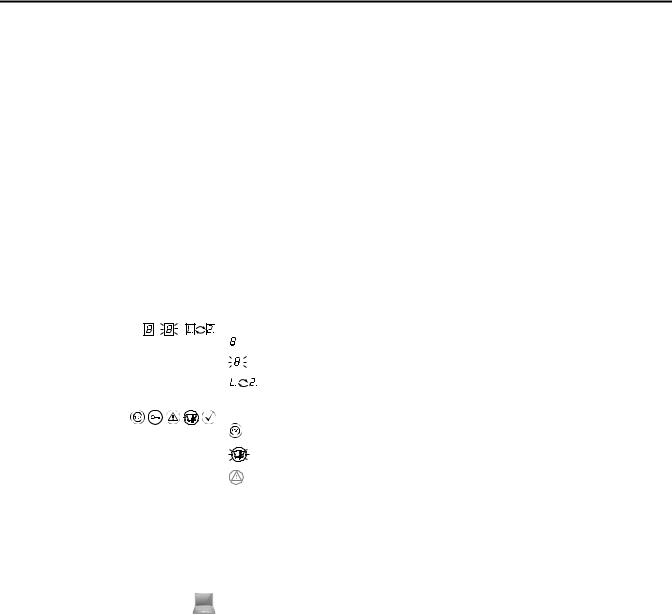
Display indicators show the status of the sevensegment display on the SafeZone Mini:
. |
|
|
|
Constant indication of characters, e.g. 8 |
|
|
|
|
|||
|
|
|
|
|
|
|
. |
|
|
Flashing indication of characters, e.g. 8 |
|
|
|
|
|
|
Alternating indication of characters, e.g. L and 2 |
|
|
|
|
|
|
LED symbols describe the status of an LED:
The “OSSDs in the OFF state” LED is illuminated continuously.
The “Error/contamination” LED is flashing.
The “Warning field interrupted” LED is off.
Instructions for taking action are shown by an arrow. Read carefully and follow the instructions for action.
A warning indicates an actual or potential risk or health hazard. Observation and implementation of the warning will protect you from accidents.
Read carefully and follow the warning notices!
Information is displayed in the software indicating to you which settings you can make in the SCD software (Safety Configuration and Diagnostic Software).
The term “dangerous state”
The dangerous state (standard term) of the machine is always shown in the drawings and diagrams of this document as a movement of a machine part. In practical operation, there may be a number of different dangerous states:
•Machine movements
•Vehicle movements
•Electrical conductors
•Visible or invisible radiation
•Combination of several risks and hazards
Rockwell Automation Publication 10000337275 Ver 01—October 2014 |
5 |

Chapter 2 |
On safety |
|
|
|
|
|
|
|
|
|
Chapter 2 |
|
|
On safety |
|
|
|
This chapter deals with your own safety and the safety of the system operators. |
|
|
|
Please read this chapter carefully before working with the SafeZone Mini or with the machine protected by the |
|
|
|
SafeZone Mini. |
|
Qualified safety personnel |
The SafeZone Mini safety laser scanner must be installed, connected, commissioned and serviced only by qualified safety |
||
|
|
personnel. Qualified safety personnel are defined as persons who: |
|
|
|
• Due to their specialist training and experience have adequate knowledge of the power-driven equipment to be |
|
|
|
checked, |
|
|
|
• Have been instructed by the responsible machine owner in the operation of the machine and the current valid safety |
|
|
|
guidelines, |
|
|
|
• Are sufficiently familiar with the applicable official health and safety regulations, directives and generally recognized |
|
|
|
engineering practice (e.g. DIN standards, VDE stipulations, engineering regulations from other EC member states) that |
|
|
|
they can assess the work safety aspects of the power-driven equipment, and |
|
|
|
• Have access to these operating instructions and have read them. |
|
|
|
As a rule these are qualified safety personnel from the ESPE manufacturer or also those persons who have been |
|
|
|
appropriately trained at the ESPE manufacturer, are primarily involved in checking ESPE and are allocated the task by the |
|
|
|
organization operating the ESPE. |
|
Applications of the device |
The SafeZone Mini safety laser scanner is used to protect persons and systems. It is intended to be used to monitor |
||
|
|
hazardous areas indoors. |
|
|
|
• It is not allowed to use the SafeZone Mini outdoors. |
|
|
|
• The SafeZone Mini cannot provide protection from parts thrown out of the machine or emitted radiation. |
|
|
|
• The SafeZone Mini complies with the requirements in the standard on the radiated emissions as defined for class A |
|
|
|
(industrial application); the SafeZone Mini is therefore only suitable for use in an industrial environment. |
|
|
|
• The device is a type 3 ESPE as defined by EN 614961 and CLC/TS 614963 and is therefore allowed for use with |
|
|
|
category 3 PL d controls as per EN ISO 138491 or SIL2 as per IEC 61508. |
|
|
|
• The SafeZone Mini is suitable for: |
|
|
|
– |
Hazardous area protection |
|
|
– |
Hazardous point protection |
|
|
– |
Access protection |
|
– Vehicle protection (electrically powered industrial trucks) |
|
Note Depending on the application, other protective devices and measures may be required in addition to the safety laser |
|
scanner. |
Correct use |
The SafeZone Mini safety laser scanner must be used only as defined in Chapter 2, “Applications of the device” on page 6. It |
|
must be used only by qualified personnel and only on the machine where it has been installed and initialized by qualified |
|
safety personnel in accordance with these operating instructions. It is only permitted to be used on machines on which the |
|
dangerous state can be stopped immediately by the SafeZone Mini and/or it is possible to prevent the machine being |
|
placed in operation. |
|
Note If the device is used for any other purposes or modified in any way — also during mounting and installation — any |
|
warranty claim against Rockwell Automation shall become void. |
6 |
Rockwell Automation Publication 10000337275 Ver 01—October 2014 |
Chapter 2 |
On safety |
|
|
General safety notes and protective measures
ATTENTION
Environmental protection
Pay attention to the safety notes!
Please observe the following items in order to ensure the correct use of the SafeZone Mini safety laser scanner.
Repair only by authorized persons!
The improper repair of the protective device can result in the loss of the protective function. The protective device is only allowed to be repaired by the manufacturer or persons authorized by the manufacturer.
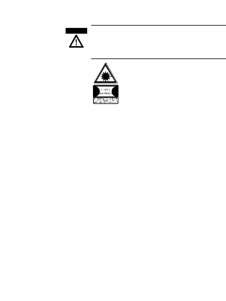
The SafeZone Mini safety laser scanner is of laser safety class 1. Additional measures for screening the laser radiation are not necessary (eye safe).
•This device meets the norms: IEC 608251 as well as CDRH 21 CFR 1040.10 and 1040.11; excluded are deviations due to Laser Notice No. 50, dated 24.06.2007. In the standards CDRH 21 CFR 1040.10 and 1040.11 the following note is required: “Caution — use of controls, adjustments or performance of procedures other than those herein specified may result in hazardous radiation exposure!”
•During the mounting, installation and usage of the SafeZone Mini, observe the standards and directives applicable in your country. You will find an overview of the most important regulations in Chapter 2, “Applicable directives and standards” on page 8.
•The national/international rules and regulations apply to the installation, commissioning, use and periodic technical inspections of the SafeZone Mini safety laser scanner, in particular …
–Machinery Directive 2006/42/EC
–Work Equipment Directive 2009/104/EC
–The work safety regulations/safety rules
–Other relevant health and safety regulations
•Manufacturers and operators of the machine on which the SafeZone Mini is used are responsible for obtaining and observing all applicable safety regulations and rules.
•The notes, in particular the test notes (see Chapter 9, “Commissioning” on page 47) in these operating instructions (e.g. on use, mounting, installation or integration into the machine control) must be observed.
•Changes to the configuration of the devices can degrade the protective function. After every change to the configuration you must therefore check the effectiveness of the protective device. The person who makes the change is also responsible for the correct protective function of the device. When making configuration changes, please always use the password hierarchy provided by Rockwell Automation to ensure that only authorized persons make changes to the configuration.
•The tests must be carried out by qualified safety personnel or specially qualified and authorized personnel and must be recorded and documented to ensure that the tests can be reconstructed and retraced at any time.
•The operating instructions must be made available to the operator of the machine where the SafeZone Mini is used. The machine operator is to be instructed in the use of the device by qualified safety personnel and must be instructed to read the operating instructions.
•To meet the requirements of the relevant product standards (e.g. EN 614961), the external voltage supply for the devices must be able to bridge a brief mains failure of 20 ms. Power supplies according to EN 602041 satisfy this requirement. Suitable power supplies are available as accessories from Rockwell Automation.
Enclosed with these operating instructions is a checklist for checking by the manufacturer and OEM (see Chapter 14, “Checklist for the manufacturer” on page 70). Use this checklist when checking the system that is protected with the SafeZone Mini.
The SafeZone Mini safety laser scanner is constructed in such a way that it adversely affects the environment as little as possible and uses only a minimum of power and natural resources.
At work, always act in an environmentally responsible manner.
Rockwell Automation Publication 10000337275 Ver 01—October 2014 |
7 |

Chapter 2 |
On safety |
|
|
Disposal
Unusable or irreparable devices should always be disposed as per the applicable national regulations on waste disposal (e.g. European waste code 16 02 14).
Note • Information on the individual materials in the SafeZone Mini is given in Chapter 12 “Technical specifications” on page 55.
Separation of materials
ATTENTION |
Only qualified safety personnel are allowed to separate materials! |
|
|
|
Caution is required when dismantling devices. There is a risk of injuries. |
Before you send the devices for appropriate recycling, it is necessary to separate the different materials in the SafeZone
Mini.
Separate the housing from the rest of the parts (in particular the circuit boards).
Send the separated parts for recycling as appropriate (see Tab. 1).
Table 1: Overview on disposal by components
Components |
Disposal |
Product |
|
Housing |
Metal recycling (aluminium) |
Motor bracket |
Metal recycling (zinc die-cast housing) |
Optics cover |
Plastic recycling |
Circuit boards, cables, connectors and electrical |
Electronic recycling |
connecting pieces |
|
|
|
Packaging |
|
Cardboard, paper |
Paper/cardboard recycling |
Polyethylene packaging |
Plastic recycling |
Applicable directives and standards
The most important directives and standards, valid for the use of opto-electronic protective devices in Europe, are listed below. Further regulations may be of importance to you, depending on the application. You can obtain further information of machine-specific standards from national institutions (e.g. DIN, BSI, AFNOR etc.), the authorities or your trade association.
If you operate the machine or vehicle in a country outside the European Union, please contact the manufacturer of the system and the local authorities and obtain information on the regulations and standards applicable there.
Application and installation of protective devices
Machinery Directive 2006/42/EC, e.g.:
•Safety of machinery — Basic concepts, general principles for design (EN ISO 12100)
•Industrial automation systems — Safety of integrated manufacturing systems — Basic requirements (ISO 11161)
•Safety of machinery — Electrical equipment of machines — Part 1: General requirements (EN 602041)
•Safety of machinery — safety distances to prevent hazard zones being reached by the upper and lower limbs (EN ISO 13857)
•Safety requirements for robots (EN ISO 102181)
•Safety of industrial trucks. Driverless trucks and their systems (EN 1525)
•Safety of machinery — The positioning of protective equipment in respect of approach speeds of parts of the human body (EN ISO 13855)
•Safety of machinery — Principles for risk assessment (EN ISO 141211)
•Safety of machinery — Safety-related parts of control systems — Part 1: General principles for design (EN ISO 138491) as well as part 2: Validation (EN ISO 138492)
•Safety of machinery — electro-sensitive protective equipment — Part 1: General requirements (EN 614961) as well as part 3: Special requirements for AOPDDR (CLC/TS 614963)
•Safety of machinery — Application of protective equipment to detect the presence of persons (IEC/TS 62046)
8 |
Rockwell Automation Publication 10000337275 Ver 01—October 2014 |
Chapter 2 |
On safety |
|
|
Regional standards, for example:
•Performance Criteria for Safeguarding (ANSI B11.19)
•Machine tools for manufacturing systems/cells (ANSI B11.20)
•Safety requirements for Industrial Robots and Robot Systems (ANSI/RIA R15.06)
•Safety Standard for guided industrial vehicles and automated functions of named industrial vehicles (ANSI B56.5)
Note To some extent these standards require the protective device to have the safety level “Control reliable.” The SafeZone
Mini safety laser scanner meets this requirement.
Rockwell Automation Publication 10000337275 Ver 01—October 2014 |
9 |
Chapter 3 Product description
Chapter 3
Product description
This chapter provides information on the special features and properties of the SafeZone Mini safety laser scanner. It describes the construction and the operating principle of the device.
Special features
•Small design
•270° scan area
•Increased dust and particle tolerance due to light saturation and particle algorithms
•With scanning ranges of two or three meters maximum protective field radii)
•Configuration using PC or notebook with Rockwell Automation SCD software
•Field sets comprising of one protective field and up to two warning fields
•Contour monitoring of the protective field if only one warning field is used
•Only standalone operation
•One field set
•One monitoring case
•Integrated external device monitoring (EDM)
•Integrated restart interlock/restart interlock delay for which the parameters can be set
•Two universal I/O connections
Function
The SafeZone Mini safety laser scanner operates correctly as a protective device only if the following conditions are met:
•The control of the machine, system or vehicle must be electrical.
•It must be possible to transfer the dangerous machine, system or vehicle state to a safe state using the OSSDs on the SafeZone Mini at any time, i.e. before a person has reached the hazardous point or hazardous area.
Or:
It must be possible to transfer the dangerous state of the machine, the system, or the vehicle to a safe state at any time using the OSSDs on a safety controller connected to the SafeZone Mini.
•The SafeZone Mini must be mounted and configured such that it detects objects as they enter the hazardous area (see Chapter 5, “Mounting” on page 35 and Chapter 9, “Commissioning” on page 47).
•The safety laser scanner’s optical path must always remain clear and is not allowed to be covered by transparent objects such as protective windows, Plexiglas, lenses etc. The safety laser scanner’s protective function can only be ensured if the contamination measurement function is not bypassed by such measures.
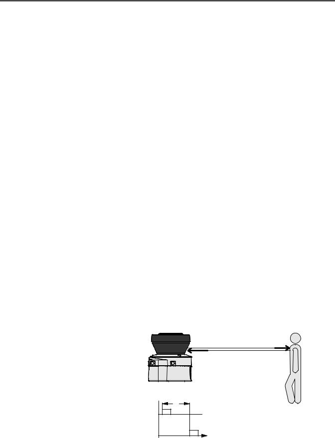
Principle of operation
The SafeZone Mini is an optical sensor that scans its surroundings in two dimensions using infrared laser beams. It is used to monitor hazardous areas on machines or vehicles.
Fig. 1: Principle of operation, |
|
time-of-flight measurement |
Send pulses |
by the SafeZone Mini |
|
|
Receive pulses |
|
SafeZone Mini |
Send pulses
Receive pulses
10 |
Rockwell Automation Publication 10000337275 Ver 01—October 2014 |
Chapter 3 Product description
Fig. 2: Principle of operation, rotation of the SafeZone Mini
The SafeZone Mini works on the principle of time-of-flight measurement. It sends out very short pulses of infrared light (send pulses). At the same time an “electronic stopwatch” is started. When the light hits an object, it is reflected and received by the safety laser scanner (receive pulses). From the time between sending and reception ( t) the SafeZone Mini calculates the distance to the object.
225°
180°
-45°
0° |
90° |
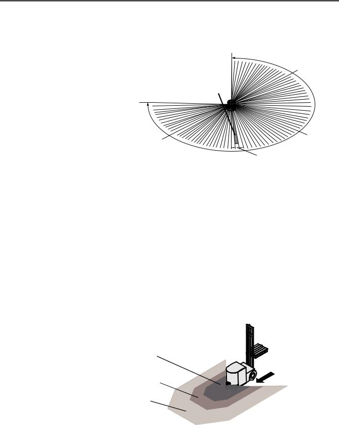
Fig. 3: Field set with one protective field and two warning fields

In the SafeZone Mini there is also a mirror rotating at constant speed that deflects the light pulses such that they cover an arc of 270°. In this way an object can be detected in the protective field within 270°. The first beam of a scan starts at –45° relative to the back of the safety laser scanner.
The SafeZone Mini sends a pulse of light with an angular resolution of 0.5° . As a result resolutions between 30 mm (1.18 in.) and 70 mm (2.76 in.) can be achieved .
Due to its active scanning principle, the SafeZone Mini does not require receivers or reflectors. This has the following advantages:
•Your installation effort is lower.
•You can easily adapt the monitored area to the hazardous area on a machine.
•In comparison with contact sensors, electro-sensitive scanning is nearly wear-free.
Field set comprising protective field and warning field(s)
Protective fields and warning fields form the so-called field set. You can configure these field sets with the aid of the SCD software. The fields can be configured as circular, rectangular or of arbitrary shape. If the area to be monitored changes, then you can re-configure the SafeZone Mini in software without additional mounting effort.
You can configure field sets comprising one protective field and one or two warning fields.
The SafeZone Mini secures the hazardous area on a machine or vehicle. As soon as the safety laser scanner detects an object in the protective field, it switches the OSSDs to the OFF state and thus initiates the shutdown of the machine or stop of the vehicle.
Protective field
Warning field
Warning field 2
You can define the warning fields such that the safety laser scanner detects an object before the actual hazardous area.
Warning field 1 can be used in particular for vehicle protection to detect an object even before the actual hazardous area and to slowly retard the movement of the vehicle or bring it to a standstill. In this way the wear on the brakes on an AGV can be reduced. Warning field 2 can also be used to trigger a warning signal.
Rockwell Automation Publication 10000337275 Ver 01—October 2014 |
11 |
Chapter 3 Product description
Note A warning field on the SafeZone Mini is not allowed to be used for tasks related to the protection of people.
Contour monitoring
In addition to the protective field, the SafeZone Mini can also monitor a contour (e.g. the floor in vertical applications).
SafeZone Mini
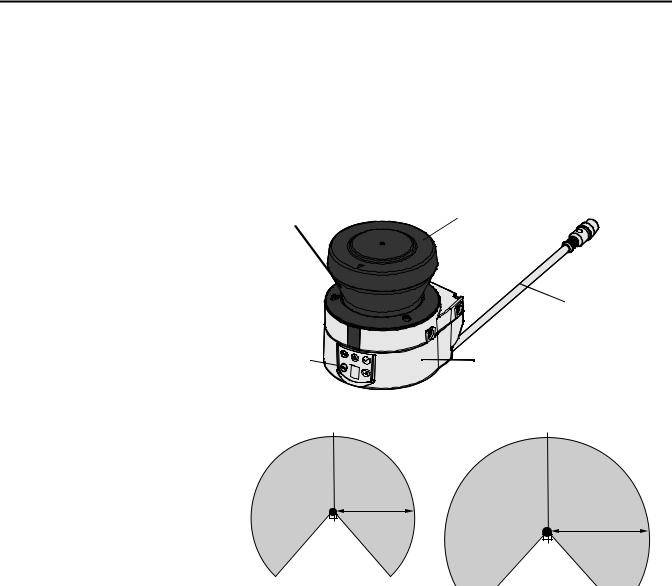
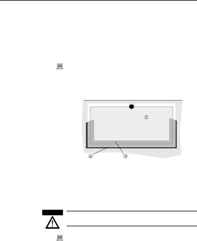
Device components
The SafeZone Mini safety laser scanner comprises three components:
•The sensor with the opto-electronic detection system, the LEDs, the sevensegment display and the connecting cable with the electrical connections
•The optics cover with the window for the light output
Fig. 4: Device components |
Window for light output |
Optics cover |
Round plug |
|
|
||
|
|
|
connector |
Connecting cable
LEDs and seven- |
Sensor |
|
segment display |
||
|
Fig. 5: Protective Field Range
Max. 2 m
(6.6 ft)
Max. 3 m
(9.84 ft)
12 |
Rockwell Automation Publication 10000337275 Ver 01—October 2014 |
|

Chapter 3 Product description
Table 2: Possible applications for the SafeZone Mini
Applications
SafeZone Mini:
Hazardous area protection on an insertion station
SafeZone Mini:
Hazardous point protection on an insertion station
SafeZone Mini:
Presence detection for a safety light curtain
SafeZone Mini:
Protection of an automated guided vehicle (AGV) for one velocity
Access protection for high areas of access
|
|
|
|
|
|
|
|
|
|
|
|
|
|
|
|
|
|
|
|
|
|
|
|
|
|
|
|
|
|
|
|
|
|
|
|
|
|
|
|
|
|
|
|
|
|
|
|
|
|
|
|
|
|
|
|
|
|
|
|
|
|
|
|
|
|
|
|
|
|
|
|
|
|
|
|
|
|
|
|
|
|
|
|
|
|
|
|
|
|
|
|
|
|
|
|
|
|
|
|
|
|
|
|
|
|
|
|
|
|
|
|
|
|
|
|
|
|
|
|
|
|
|
|
|
|
|
|
|
|
|
|
|
|
|
|
|
|
|
|
|
|
|
|
|
|
|
|
|
|
|
|
|
|
|
|
|
|
|
|
|
|
|
|
|
|
|
|
|
|
|
|
|
|
|
|
|
|
|
|
|
|
|
|
|
|
|
|
|
|
|
|
|
|
|
|
|
|
|
|
|
|
|
|
|
|
|
|
|
Rockwell Automation Publication 10000337275 Ver 01—October 2014 |
|
13 |
||||||||||||||||
Chapter 3 Product description
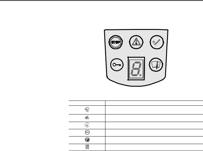
Status indicators |
LEDs and sevensegment display |
|
The LEDs and the sevensegment display indicate the operational status of the SafeZone Mini. They are on the front face of |
|
the safety laser scanner. |
Fig. 6: Status indicators on the
SafeZone Mini
The symbols have the following meaning:
Table 3: Status indicators on the |
Symbol |
SafeZone Mini |
|
SafeZone Mini |
|||
|
OSSDs in the OFF state (e.g. in case of object in the protective field, monitored contour |
||
|
|
||
|
|
changed, reset required, lockout) |
|
|
|
Warning field interrupted (object in one of the warning fields) |
|
|
|
OSSDs in the ON state (no object in protective field) |
|
|
|
Reset required |
|
|
|
Optics cover contaminated |
|
|
. |
Sevensegment display for the indication of the status and errors |
|
|
|
Note You will find detailed information in Chapter 11, “Error and status indications on the LEDs” on page 52 and in “Error and status indications on the sevensegment display” on page 52).
14 |
Rockwell Automation Publication 10000337275 Ver 01—October 2014 |

Chapter 4 Configurable functions
Chapter 4
Configurable functions
System parameters
A name can be assigned to the application configured as well as to the safety laser scanner(s). The names are saved in the devices after the configuration is transferred. The name chosen may be, for example, the identifier for the vehicle, system or the machine.
You enter the application name and the names of the safety laser scanners used in the SCD software.
Application name
Enter a name for your application. You can enter a name with a maximum of 16 characters.
If you assign unique application names, you may “reserve” the devices for certain duties. A machine maintenance person comparing exchanged devices with the configuration data saved in the SCD software will be notified that the application name does not match. He may then exchange these devices for those with the correct application name.
Name of the scanner
Enter a device name for each of the safety laser scanners in the system. You can enter names with a maximum of eight characters.
Recommendation Use meaningful names, e.g. “front” and “rear” for vehicle monitoring. Unique device names make the subsequent configuration steps easier (for example on allocating the control inputs or the OSSDs).
User data
You can enter your name in the field Name of the user. You can enter a name with a maximum of 22 characters. This is then added to the configuration protocol and in the diagnostics report.
Display direction of the sevensegment display
The depiction of numbers on the sevensegment display can be rotated by 180° with the aid of the SCD software. This is useful, for example, when the SafeZone Mini must be rotated by 180° owing to the specific assembly.
If you rotate the numbers of the sevensegment display, the point in the sevensegment display goes out.
How to determine the display direction of the sevensegment display:
Under sevensegment display, activate the Rotated by 180° option. After the configuration draft has been transferred to the SafeZone Mini, the numbers of the sevensegment display are rotated by 180°.
Rockwell Automation Publication 10000337275 Ver 01—October 2014 |
15 |
Chapter 4 Configurable functions
Application
Table 4: Comparison of mobile and stationary applications
Table 5: Maximum protective field range at different resolutions
With the help of the SCD software you can configure the SafeZone Mini for the required application. Depending on whether you select a stationary or a mobile application, different configuration options are available:
|
|
Mobile applications [mm (in.)] |
|
Stationary applications [mm (in.)] |
|
Resolution |
|
|
|
||
• 30 |
(1.2) |
(hand detection with smaller protective field |
• 30 |
(1.2) |
(hand detection with smaller protective field |
size) |
|
size) |
|
||
• 40 |
(1.6) |
(hand detection with larger protective field |
• 40 |
(1.6) |
(hand detection with larger protective field |
size) |
|
size) |
|
||
• 50 |
(2.0) |
(leg detection with smaller protective field |
• 50 |
(2.0) |
(leg detection with smaller protective field |
size) |
|
size) |
|
||
• 70 |
(2.8) |
(leg detection with larger protective field |
• 70 |
(2.8) (leg detection with larger protective field size) |
|
size) |
|
• 150 (5.9) (whole body detection) |
|||
|
|
|
|
|
|
Manipulation prevention
The safety laser scanner checks whether in any 90° segment all measured values correspond to the maximum distance value that can be measured.
If this is the case, the SafeZone Mini shuts down after |
If this the case, the SafeZone Mini shuts down after |
||||||||
2 hours and signals |
|
|
|
. |
5 seconds and signals |
|
|
|
. |
|
|
|
|
|
|
||||
|
|
|
|
||||||
|
|
|
|
|
|
|
|
|
|
Resolution
The maximum protective field range depends on the configured resolution. The following table shows the related maximum protective field range at the resolutions that can be set:
Configured resolution [mm (in.)] |
Maximum protective field range [m (ft)] |
||
|
2 m |
|
3 m |
30 (1.2) – (hand detection) |
1.25 (4.1) |
|
1.25 (4.1) |
40 (1.6) – (hand detection) |
1.60 (5.2) |
|
1.60 (5.2) |
50 (2.0) – (leg detection) |
2.00 (6.6) |
|
2.10 (6.89) |
70 (2.8) – (leg detection) |
2.00 (6.6) |
|
3.00 (9.84) |
150 (5.9) (whole body detection) |
|
3.00 |
(9.84) |
Note The warning field can be configured to up to 8 m (26.25 ft) for all resolutions. The detection capability within the warning field is dependent on the remission of the objects to be detected (see Chapter 12, “Technical Specifications” on page 55).
Basic response time
The basic response time of the SafeZone Mini is 80 ms.
Note You may need to add supplements to the basic response time due to multiple sampling (see Chapter 12, “OSSD response times” on page 55).
Maximum protective field range
Depending on the configured resolution used (see Chapter 4, “Resolution” on page 16), the maximum protective field range of the safety laser scanner is shown in the SCD software.
Note The maximum protective field range of the SafeZone Mini must be sufficient to cover the calculated protective field size including the necessary supplements (see Chapter 5, “Protective field size” on page 25).
In mobile applications a resolution of only 70 mm (2.8 in.) is required for leg detection.Radial distance to the safety scanner.
16 |
Rockwell Automation Publication 10000337275 Ver 01—October 2014 |
Chapter 4 Configurable functions
Universal I/O connections of the SafeZone Mini
ATTENTION
You are not allowed to use the universal I/O connections for safety-relevant functions!
You are only allowed to use the universal I/O connections for signaling. You must never use the signals for controlling the application or for safety-relevant functions.
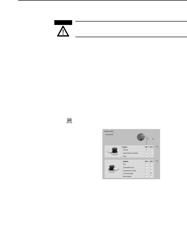
The SafeZone Mini has two universal I/O connections (see Chapter 6, “Round plug connector SafeZone Mini” on page 40). You can configure these two connections for the following functions:
• Inactive (factory default setting)
As inputs (it is only possible to select one function per universal I/O connection):
•Stand-by
•External device monitoring (EDM) (see page 18)
•Resetting the restart interlock (see page 18)
As outputs (it is possible to select several functions per universal I/O connection, these functions are linked together using an OR operator):
•Device error
•Contamination error
•Contamination warning
•Second warning field
•Reset required
Note Other functions that can be configured are dependent on the configuration of the universal I/O connections. For example, you can only realize a restart interlock if you configure one of the universal I/Os as an input for resetting the restart interlock.
The universal I/O connections are configured in the SCD software in the Universal I/O area. Fig. 7 shows a configuration example.
Fig. 7: Configuration example universal I/O connections of the SafeZone Mini
Stand-by
If, in mobile applications, vehicles are not moved for a time, the OSSDs can be switched to the OFF state and the laser on the SafeZone Mini can be switched off. In this way the power consumption of the device is reduced.
Recommendation Use this function if, e.g. you use several vehicles and do not move them for a time.
The SafeZone Mini remains in the stand-by mode as long as the related input information is present.
Rockwell Automation Publication 10000337275 Ver 01—October 2014 |
17 |
Chapter 4 Configurable functions
OSSDs |
Internal OSSDs of the SafeZone Mini |
Table 6: Behavior of the SafeZone Mini on a contactor malfunction
If there is an object in the protective field, the internal OSSDs on the SafeZone Mini always switch. This can not be configured differently in the SCD software.
External device monitoring (EDM) SafeZone Mini
The EDM checks if the contactors actually de-energize when the protective device is tripped. If you activate external device monitoring, then the SafeZone Mini checks the contactors after each interruption of the protective field and prior to the machine restart. The EDM can so identify if one of the contactors has welded, for instance. In this case the external device monitoring places the system in a safe operational state and the OSSDs are not switched back to the ON state.
The table shows how the SafeZone Mini reacts if the external device monitoring detects a contactor malfunction:
Without internal restart interlock |
• |
The system locks completely (lock-out). |
|||
or |
• |
The error message 8 appears in the sevensegment display. |
|||
with restart delay |
|||||
|
|
|
|
|
|
With restart interlock |
• |
The SafeZone Mini switches its OSSDs to the OFF state. |
|||
|
• |
The LED |
is illuminated. |
||
|
|
|
|
|
|
|
• |
The error message |
. |
e appears in the sevensegment display. |
|
|
|
||||
|
|
|
|
|
|
You can configure the external device monitoring in the SCD software.
Note
Restart of the SafeZone
Mini Standard
ATTENTION
You will find examples on the connection of the external device monitoring in Chapter 7, “Connection diagrams” on page 43.
You can configure the restart behavior of the SafeZone Mini as follows:
•Without restart interlock
•With restart delay
•With restart interlock
You can configure the type of restart in the SCD software.
It is imperative that you configure the SafeZone Mini or the application with restart interlock if the protective field can be left to approach the hazardous point or if a person cannot be detected by the SafeZone Mini at every point in the hazardous area!
During the assessment, pay attention to whether the protective field can be left in the direction of the hazardous point, to areas that are unprotected due to the mounting and the unprotected near range of the SafeZone Mini (see Chapter 5, “Methods of preventing unprotected areas” on page 33).
Configuration of the SafeZone Mini without restart interlock
After the OSSDs on the SafeZone Mini have been switched to the OFF state due to an object in the protective field, the OSSDs are re-enabled again immediately when there is no longer an object in the active protective field.
This configuration is only allowed …
• If an external restart interlock is realized on the machine controller
or
•If the protective field cannot be left in the direction of the hazardous point and if people can be detected by the SafeZone Mini at every point in the hazardous area!
Restart delay for mobile applications
In mobile applications you can configure a restart delay from 2 to 60 seconds on the SafeZone Mini. The OSSDs on the SafeZone Mini change to the ON state if there is no object in the protective field for the duration given.
This configuration is only allowed if the protective field cannot be left in the direction of the hazardous point and if a person can be detected at every point in the hazardous area by the SafeZone Mini!
18 |
Rockwell Automation Publication 10000337275 Ver 01—October 2014 |
Chapter 4 Configurable functions
Configuration of the SafeZone Mini with restart interlock
Fig. 8: Schematic outline of the operation with restart interlock
Note
Do not confuse the restart interlock with the starting interlock on the machine. The starting interlock prevents the machine starting after switching on. The restart interlock prevents the machine starting again after an error or a protective field infringement.
The OSSDs on the SafeZone Mini change to the OFF state to initiate a machine or vehicle stop as soon as there is an object in the protective field . They do not change to the ON state , even if there is no longer an object in the protective field. The OSSDs only change to the ON state if the operator operates the control switch for restart or reset.
ATTENTION
Place the control switch for restart or reset outside the hazardous area in a place where it can clearly be seen from the hazardous area!
Place the control switch for restart or reset outside the hazardous area such that it cannot be operated by a person in the hazardous area. Ensure that the person who operates the control switch has a full view of the hazardous area.
Notes • You will find examples on the connection of the internal restart interlock in Chapter 7, “Connection diagrams” on page 43.
•If you do not use the internal restart interlock, then do not configure any of the universal I/Os as an input for resetting (see Chapter 4, “Universal I/O connections of the SafeZone Mini” on page 17).
Reset
Note The reset function is often also called “preparation for restart.” In these operating instructions the term reset is used.
If you want to activate the restart interlock on the SafeZone Mini (internal) and also a restart interlock on the machine (external), then each restart interlock has its own control switch.
After operating the control switch for the internal restart interlock (with protective field unoccupied) …
•The SafeZone Mini switches its OSSDs to the ON state.
•The LED  on the SafeZone Mini illuminates green.
The external restart interlock prevents the machine from restarting. After resetting the SafeZone Mini the operator must press the control switch to restart the machine controller.
ATTENTION
Ensure that the correct sequence is followed!
The controller must be realized such that the machine only restarts if the SafeZone Mini is first reset and then the control switch for restarting the machine controller is operated.
Reset signals
If the SafeZone Mini safety laser scanner is operated using the “With restart interlock” function, then after a protective field infringement and the subsequent clearing of the protective field, it requests a reset signal from the control system (reset required).
ATTENTION
The reset signal must be safety-related (single failure proof)!
Rockwell Automation Publication 10000337275 Ver 01—October 2014 |
19 |
Chapter 4 Configurable functions
Field sets |
Configuring the protective field and warning field |
|
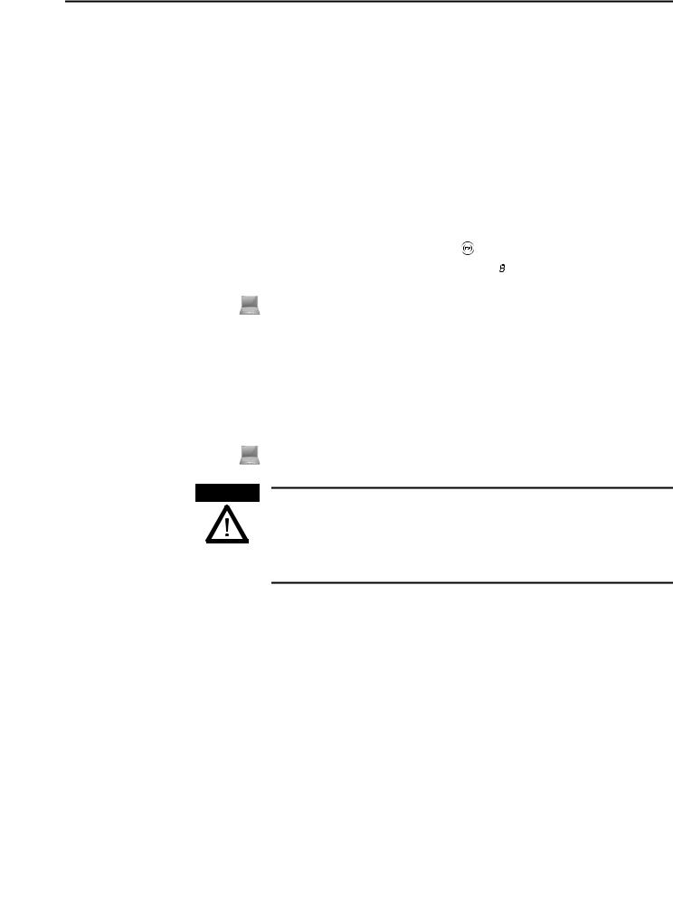
With the aid of the SCD software you can configure the field set, which comprises a protective field and two warning |
|
fields . During this process you configure the shape and size of the protective and warning fields. You can realize any |
|
field shape required. |
Fig. 9: Creating a field set in the SCD software
Note The area to be monitored is scanned radially by the SafeZone Mini. The SafeZone Mini cannot see through objects during this process. The area behind objects that are in the area to be monitored (pillars, grilles, etc.) can thus not be monitored.
Protective fields and warning field can cover up an angle of up to 270° and have different radial scanning ranges depending on the resolution configured (see Chapter 4, “Resolution” on page 16).
ATTENTION
Check the protective fields configured!
Prior to commissioning the machine or vehicle, check the configuration of the protective fields using the instructions in
Chapter 9, “Commissioning” on page 47 and using the “Checklist” on page 70.
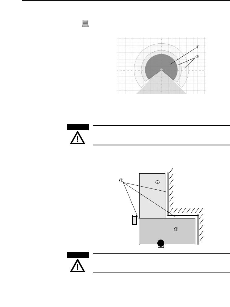
Note If the protective field or the warning fields stretch as far as a wall or another object (pillar, neighboring machine, shelf), there should be a distance of 100 mm (3.94 in.) between the protective field or warning field and the object to prevent false triggering .
Fig. 10: Configuring protective field and warning field
ATTENTION
Secure unprotected areas!
If it is possible to access a narrow strip between the protective field and a wall or another object, you must protect this strip using additional measures (e.g. fence or floor protection).
20 |
Rockwell Automation Publication 10000337275 Ver 01—October 2014 |
Chapter 4 Configurable functions
Protective field or warning field suggested by the safety laser scanner
The SCD software can suggest the protective field or warning field in the field set editor. The safety laser scanner scans the visible surrounding contour several times. From the data obtained the SCD software suggests the contour and size of the field. The following figure shows an example for the reading of a protective field:
Fig. 11: Reading the protective field
In those places at which the surrounding contour is smaller than the maximum protective field range (e.g. at ), the protective field corresponds to the surrounding contour.
Note The measuring error tolerances for the SafeZone Mini are automatically subtracted from the protective field size. As a result the protective field is slightly smaller than the surface covered .
In those places where the surrounding contour is larger than the protective field range , the protective field corresponds to the possible scanning range.
ATTENTION
Check the protective field suggested by the SCD software
The protective field suggested by the SCD software is not a replacement for the calculation of the minimum distance. Calculate the minimum distance and check the effectiveness of the protective fields prior to commissioning the application!
Pay attention to the descriptions in Chapter 5, “Mounting” on page 24, the notes in Chapter 9, “Commissioning” on page 47 and the “Checklist” on page 70.
Using the contour as a reference
In addition to the protective field, the SafeZone Mini can also monitor a contour (e.g. the floor in vertical applications).
Fig. 12: Schematic diagram of contour as reference
For contour monitoring you define a contour segment . The contour segment comprises a positive and a negative tolerance band.
Rockwell Automation Publication 10000337275 Ver 01—October 2014 |
21 |
Chapter 4 Configurable functions
The OSSDs on the SafeZone Mini change to the OFF state or the SafeZone Mini Remote signals if …
•There is an object in the protective field.
•The monitored surrounding contour is no longer in the tolerance band (e.g. if the position of the SafeZone Mini is changed).
Notes • You can define any number of contour segments.
•The contour segments must not be narrower than the configured resolution.
•At the points where a contour has been configured as a reference you cannot define warning fields. If, for example, you use the floor as a reference for access protection, you cannot configure a warning field there. However, you can, e.g., configure a warning field to the left and right of the contour segment to control a warning signal on approach from the side.
•The contour as reference function and the warning field 2 function are mutually exclusive.
You define the contour as a reference in the SCD software field set editor.
Vertical operation
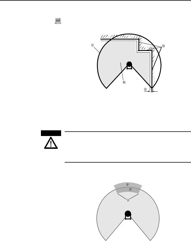
In vertical operation (for access protection and hazardous point protection) according to CLC/TS 614963 you must always configure the protective fields used with the contour as reference function.
Fig. 13: Contour as reference for vertical operationProtective field
Contours of the machine openingContour segment
Recommendation Use lateral, vertical boundaries of the opening (e.g. door frame) and the floor as reference. If in this case the position of the SafeZone Mini is changed in one or more planes, the distance to the reference changes and the SafeZone Mini switches its OSSDs to the OFF state.
Monitoring cases |
The SafeZone Mini supports a configuration with monitoring cases. |
ATTENTION
Ensure for each monitoring case that the minimum distance to the hazardous area is maintained!
See Chapter 5, “Mounting” on page 24.
You can configure the monitoring cases in the SCD software.
Each monitoring case includes …
•The input conditions, the so-called control signals, that control the activation of the monitoring case.
•A field set, comprising of protective field and warning field or fields.
•The multiple sampling for the field set.
Monitoring cases can be switched with the following input information:
• Static information
22 |
Rockwell Automation Publication 10000337275 Ver 01—October 2014 |
 Loading...