


 Loading...
DSI Wireless
Interface Module
22-WIM-N1
22-WIM-N4S
FRN 1.xxx
User Manual

Important User Information
Solid state equipment has operational characteristics differing from those of electromechanical equipment. Safety Guidelines for the Application, Installation and Maintenance of Solid State Controls (Publication SGI-1.1 available from your local Rockwell Automation sales office or online at http://www.rockwellautomation.com/ literature) describes some important differences between solid state equipment and hard-wired electromechanical devices. Because of this difference, and also because of the wide variety of uses for solid state equipment, all persons responsible for applying this equipment must satisfy themselves that each intended application of this equipment is acceptable.
In no event will Rockwell Automation, Inc. be responsible or liable for indirect or consequential damages resulting from the use or application of this equipment.
The examples and diagrams in this manual are included solely for illustrative purposes. Because of the many variables and requirements associated with any particular installation, Rockwell Automation, Inc. cannot assume responsibility or liability for actual use based on the examples and diagrams.
No patent liability is assumed by Rockwell Automation, Inc. with respect to use of information, circuits, equipment, or software described in this manual.
Reproduction of the contents of this manual, in whole or in part, without written permission of Rockwell Automation, Inc. is prohibited.
Throughout this manual, when necessary we use notes to make you aware of safety considerations.
WARNING: Identifies information about practices or circumstances that can cause an explosion in a hazardous environment, which may lead to personal injury or death, property damage, or economic loss.
Important: Identifies information that is critical for successful application and understanding of the product.
ATTENTION: Identifies information about practices or circumstances that can lead to personal injury or death, property damage, or economic loss. Attentions help you, identify a hazard, avoid the hazard, and recognize the consequences.
Shock Hazard labels may be located on or inside the equipment (e.g., drive or motor) to alert people that dangerous voltage may be present.
Burn Hazard labels may be located on or inside the equipment (e.g., drive or motor) to alert people that surfaces may be at dangerous temperatures.
Allen-Bradley, PowerFlex, Pocket DriveExplorer for Pocket PC, DriveExplorer, and DriveExecutive are either registered trademarks or trademarks of Rockwell Automation, Inc.
The Bluetooth® word mark and logos are owned by the Bluetooth SIG, Inc. DeviceNet is a trademark of the Open DeviceNet Vendor Association. ControlNet is a trademark of ControlNet International Ltd.
Windows and Microsoft are registered trademarks of Microsoft Corp.

Summary of Changes
The information below summarizes the changes made to this manual since its last release (July 2005):
Description of Change |
Page(s) |
In Chapter 3 in the “Using Pocket DriveExplorer for Pocket PC” section, added |
3-8 |
the new subsection “Assigning a Name for the WIM.” |
|
In Chapter 3 in the “Using DriveExplorer/DriveExplorer Lite” section, added the |
3-14 |
new subsection “Assigning a Name for the WIM.” |
|
In Chapter 3 in the “Using DriveExecutive” section, added the new subsection |
3-23 |
“Assigning a Name for the WIM.” |
|
The information below summarizes the changes made to this manual since its last release (March 2005):
Description of Change |
Page(s) |
|
In Chapter 1: |
|
|
• |
In section “Equipment Shipped with the WIM,” added categories and items |
1-3 |
• |
for 22-WIM-N1 and 22-WIM-N4S. |
1-5 |
In Step 3 of the Quick Start table: |
||
–Corrected Comm Flt Action parameter number from “02” to “07.”
–Corrected Security Mode parameter number from “03” to “05.”
–Corrected Security PIN parameter number from “04” to “06.”
–Added “Use the RTU Master mode to …” and a reference to Appendix D.
In Chapter 3 in subsection “To reset a PIN number when misplaced or |
3-26 |
forgotten,” added information to retrieve a stored PIN number. |
|

soc-ii Summary of Changes

Table of Contents
Preface |
About This Manual |
|
|
Related Documentation . . . . . . . . . . . . . . . . . . . . . . . . . . . . . |
P-1 |
|
Rockwell Automation Support. . . . . . . . . . . . . . . . . . . . . . . . |
P-2 |
|
Conventions Used in This Manual . . . . . . . . . . . . . . . . . . . . . |
P-3 |
|
Third-Party Bluetooth Support. . . . . . . . . . . . . . . . . . . . . . . . |
P-3 |
Chapter 1 |
Getting Started |
|
|
Components . . . . . . . . . . . . . . . . . . . . . . . . . . . . . . . . . . . . . |
1-1 |
|
Features . . . . . . . . . . . . . . . . . . . . . . . . . . . . . . . . . . . . . . . . . |
1-2 |
|
Compatible Products . . . . . . . . . . . . . . . . . . . . . . . . . . . . . . . |
1-2 |
|
Required Equipment . . . . . . . . . . . . . . . . . . . . . . . . . . . . . . . |
1-3 |
|
Safety Precautions . . . . . . . . . . . . . . . . . . . . . . . . . . . . . . . . . |
1-4 |
|
Quick Start . . . . . . . . . . . . . . . . . . . . . . . . . . . . . . . . . . . . . . |
1-5 |
|
Status Indicator . . . . . . . . . . . . . . . . . . . . . . . . . . . . . . . . . . . |
1-6 |
Chapter 2 |
Installing the WIM |
|
|
Installing the NEMA 1 WIM (22-WIM-N1) . . . . . . . . . . . . |
2-1 |
|
Installing the NEMA 4 WIM (22-WIM-N4S) . . . . . . . . . . . |
2-2 |
|
Removing the NEMA 1 WIM (22-WIM-N1) . . . . . . . . . . . . |
2-4 |
Chapter 3 |
Configuring the WIM |
|
|
Configuration Tools . . . . . . . . . . . . . . . . . . . . . . . . . . . . . . |
. 3-1 |
|
Using Pocket DriveExplorer for Pocket PC. . . . . . . . . . . . . . |
3-2 |
|
Using DriveExplorer/DriveExplorer Lite. . . . . . . . . . . . . . . |
3-10 |
|
Using DriveExecutive . . . . . . . . . . . . . . . . . . . . . . . . . . . . . |
3-16 |
|
Setting the Fault Action . . . . . . . . . . . . . . . . . . . . . . . . . . . . |
3-24 |
|
Enabling and Setting the Security Mode . . . . . . . . . . . . . . . |
3-25 |
|
Resetting the WIM. . . . . . . . . . . . . . . . . . . . . . . . . . . . . . . . |
3-26 |
Chapter 4 |
Troubleshooting |
|
|
Understanding the Status Indicator . . . . . . . . . . . . . . . . . . . . |
4-1 |
|
Viewing WIM Diagnostic Items . . . . . . . . . . . . . . . . . . . . . . |
4-3 |
|
Viewing and Clearing Events . . . . . . . . . . . . . . . . . . . . . . . . |
4-4 |
|
Viewing and Clearing DF1 Communication Statistics . . . . . |
4-5 |
Appendix A Specifications
Communications . . . . . . . . . . . . . . . . . . . . . . . . . . . . . . . . . |
A-1 |
Electrical . . . . . . . . . . . . . . . . . . . . . . . . . . . . . . . . . . . . . . . |
A-1 |
Mechanical . . . . . . . . . . . . . . . . . . . . . . . . . . . . . . . . . . . . . |
A-1 |
Environmental . . . . . . . . . . . . . . . . . . . . . . . . . . . . . . . . . . . |
A-2 |
Regulatory Compliance . . . . . . . . . . . . . . . . . . . . . . . . . . . . |
A-2 |

ii |
Table of Contents |
|
|
Appendix B WIM Parameters
About Parameter Numbers. . . . . . . . . . . . . . . . . . . . . . . . . . . B-1
Parameter List . . . . . . . . . . . . . . . . . . . . . . . . . . . . . . . . . . . . B-1
Appendix C Wireless Flash Updating DSI Peripherals
Using Pocket DriveExplorer for Pocket PC . . . . . . . . . . . . . C-1
Using DriveExplorer/DriveExplorer Lite . . . . . . . . . . . . . . . C-6
Using DriveExecutive . . . . . . . . . . . . . . . . . . . . . . . . . . . . . C-11
Appendix D Using RTU Master Mode
Establishing Wireless Connection . . . . . . . . . . . . . . . . . . . . D-1 Configuring the Drive Parameters . . . . . . . . . . . . . . . . . . . . D-2 Configuring the WIM for RTU Master Mode . . . . . . . . . . . D-4 System Wiring . . . . . . . . . . . . . . . . . . . . . . . . . . . . . . . . . . . D-6 Accessing the Drives on RTU Master Network . . . . . . . . . . D-8
Glossary
Index

Preface
About This Manual
Topic |
Page |
Related Documentation |
P-1 |
Rockwell Automation Support |
P-2 |
Conventions Used in This Manual |
P-3 |
Third-Party Bluetooth Support |
P-3 |
Related Documentation
For: |
Refer to: |
Publication |
Pocket DriveExplorer™ |
http://www.ab.com/drives/driveexplorer, and |
— |
for Pocket PC |
Pocket DriveExplorer for Pocket PC online help |
|
|
(installed with the software) |
|
DriveExplorer™ |
http://www.ab.com/drives/driveexplorer, and |
— |
|
DriveExplorer online help (installed with the software) |
|
DriveTools™ SP (includes |
http://www.ab.com/drives/drivetools, and |
— |
DriveExecutive™) |
DriveExecutive online help (installed with the software) |
|
HIM |
HIM Quick Reference |
22HIM-QR001… |
PowerFlex® 4 Drive |
PowerFlex 4 User Manual |
22A-UM001… |
|
PowerFlex 4 Quick Start |
22A-QS001… |
PowerFlex® 40 Drive |
PowerFlex 40 User Manual |
22B-UM001… |
|
PowerFlex 40 Quick Start |
22B-QS001… |
PowerFlex® 400 Drive |
PowerFlex 400 User Manual |
22C-UM001… |
RSLinx™ |
Getting Results with RSLinx Guide, |
LINX-GR001… |
or RSLinx Lite |
and online help (installed with the software) |
|
Bluetooth® wireless |
http://www.Bluetooth.org or |
— |
technology |
http://www.Bluetooth.com |
|
Documentation can be obtained online at
http://www.rockwellautomation.com/literature.

P-2 About This Manual
Rockwell Automation Support
Rockwell Automation, Inc. offers support services worldwide, with over 75 sales/support offices, over 500 authorized distributors, and over 250 authorized systems integrators located through the United States alone. In addition, Rockwell Automation, Inc. representatives are in every major country in the world.
Local Product Support
Contact your local Rockwell Automation, Inc. representative for:
•Sales and order support
•Product technical training
•Warranty support
•Support service agreements
Technical Product Assistance
If you need to contact Rockwell Automation, Inc. for technical assistance, please review the information in Chapter 4, Troubleshooting, first. If you still have problems, then access the Allen-Bradley Technical Support web site at www.ab.com/support/abdrives.

About This Manual |
P-3 |
|
|
Conventions Used in This Manual
The following conventions are used throughout this manual:
•Parameter names are shown in the format Parameter xx - [*]. The xx represents the parameter number, and the * represents the parameter name — for example Parameter 01 - [Adapter Cfg].
•Menu commands are shown in bold type face and follow the format Menu > Command. For example, if you read “Select File > Open,” you should click the File menu and then click the Open command.
•The firmware release is displayed as FRN X.xxx. The “FRN” signifies Firmware Release Number. The “X” is the major release number. The “xxx” is the minor update number.
•Pocket DriveExplorer for Pocket PC (version 1.01), My Bluetooth Places software (version 1.4.2), DriveExplorer Lite (version 4.04), and DriveExecutive (version 3.01) were used for the screen pictures in this manual. Different versions of the software may differ in appearance and procedures.
•This manual provides information about the 22-WIM-N* Wireless Interface Module (WIM) and using it with PowerFlex 4-Class drives. The module can be used with other products that support DSI.
Third-Party Bluetooth Support
Since the WIM requires a Pocket PC, laptop PC or desktop PC equipped with Bluetooth wireless technology, you may need to install a third-party, vendor-specific Bluetooth driver. If this driver fails to establish wireless communication with the WIM, refer to its documentation for assistance. Furthermore, troubleshooting help may be available on the vendor web site.

P-4 About This Manual
Notes:
Chapter 1
Getting Started
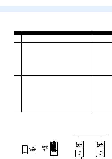
The 22-WIM-N* Wireless Interface Module (WIM) provides a wireless communications interface between a Pocket PC, laptop computer or desktop computer equipped with Bluetooth wireless technology and any Allen-Bradley product supporting DSI. The WIM uses the full-duplex DF1 protocol.
Topic |
Page |
Components |
1-1 |
Features |
1-2 |
Compatible Products |
1-2 |
Required Equipment |
1-3 |
Safety Precautions |
1-4 |
Quick Start |
1-5 |
Status Indicator |
1-6 |
Components
Figure 1.1 Components of the WIM
Contains FCC ID: SNT-2XWIMNX
IC: 5450A-2XWIMNX
This device complies with Part 15 of the FCC rules. Operation is subject to the following two conditions:
1)this device may not cause harmful interference, and
2)this device must accept any interference received, including interference that may cause undesired operation
(NEMA 1 WIM shown)
Item |
Part |
Description |
|
Status |
LED that indicates WIM |
|
Indicator |
operation, when data is being |
|
|
received from the Bluetooth |
|
|
wireless technology enabled |
|
|
Pocket PC or computer, and |
|
|
when data is being sent to |
|
|
the Pocket PC or computer. |
|
|
Refer to Status Indicator on |
|
|
page 1-6 and Chapter 4, |
|
|
Troubleshooting for more |
|
|
information. |

1-2 Getting Started
Features
Features of the WIM include the following:
•A status indicator (LED) that reports the operating status of the module.
•Connectivity to products implementing DSI, such as PowerFlex 4-Class drives and peripherals. When used with a product, the WIM will autobaud to the DSI data rate that is used by the product.
•The WIM receives power from the drive. An outside power source is not needed.
•An RTU Master operating mode for use on an RTU Master network to monitor, configure, and control up to 32 PowerFlex 4-Class drives using wireless communication and Allen-Bradley drive software tools.
•The following tools can be used to configure the WIM:
–Pocket DriveExplorer for Pocket PC (version 1.01 or higher)
–DriveExplorer (version 4.04 or higher)
–DriveExecutive (version 3.01 or higher)
–PowerFlex 4-Class HIM
•The WIM can be used with compatible Allen-Bradley software tools through wireless communication to flash upgrade itself and other DSI peripherals (PowerFlex 4-Class HIMs and communication adapters) to take full advantage of new firmware features as they become available.
Compatible Products
DSI is based on the Modbus RTU serial communication protocol. The WIM can be used with Allen-Bradley Component Class (PowerFlex 4-Class) drives and other products that support DSI. At the time of publication, compatible products include all the following types of:
•PowerFlex 4 drives
•PowerFlex 40 drives
•PowerFlex 40P drives
•PowerFlex 400 drives

Getting Started |
1-3 |
|
|
Required Equipment
Equipment Shipped with the WIM
When you unpack the WIM, verify that the package includes:
22-WIM-N1
One Wireless Interface Module
This manual
22-WIM-N4S
One Wireless Interface Module
One 22-HIM-H30 Cable
This manual
User-Supplied Equipment
To configure the WIM, you must use one of the following:
Pocket DriveExplorer for Pocket PC software (version 1.01 or higher) running on a Pocket PC equipped with Bluetooth wireless technology
DriveExplorer software (version 4.04 or higher) running on a laptop or desktop computer equipped with Bluetooth wireless technology
DriveExecutive stand-alone software (version 3.01 or higher) or bundled with the DriveTools SP suite (version 1.01 or higher) running on a laptop or desktop computer equipped with Bluetooth wireless technology
PowerFlex 4-Class HIM (22-HIM-*)

1-4 Getting Started
Safety Precautions
Please read the following safety precautions carefully.
!
!
!
ATTENTION: Risk of injury or death exists from machine motion when using wireless communications and software to Start/Stop/Jog,  configure or otherwise communicate with a drive.
Using the control bar feature in Pocket DriveExplorer for Pocket PC, DriveExplorer or DriveExecutive with wireless communications may present safety hazards due to potential loss of the wireless connection. For example, if the wireless connection is interrupted after a start or jog command is initiated from the control bar, the drive cannot be stopped using the control bar until the wireless connection is restored. For this reason, it is required to always use an additional hard-wired stop circuit to disable the drive.
ATTENTION: Risk of injury or equipment damage exists. Only personnel familiar with drive and power products and the associated  machinery should plan or implement the installation, start-up, configuration, and subsequent maintenance of the product using a WIM. Failure to comply may result in injury and/or equipment damage.
ATTENTION: Risk of injury or equipment damage exists.
Parameter 02 - [Comm Flt Action] lets you determine the action of  the WIM and connected drive if DF1 serial communications are
disrupted. By default, this parameter faults the drive. You can set this parameter so that the drive continues to run. Precautions should be taken to ensure that the setting of this parameter does not create a risk of injury or equipment damage. When commissioning the drive, verify that your system responds correctly to various situations (for example, a communication disruption or a faulted controller).
Getting Started |
1-5 |
|
|
Quick Start
This section is designed to help experienced users quickly start using the WIM. If you are unsure how to complete a step, refer to the referenced chapter.
Step |
Action |
|
|
Refer to… |
1 |
Review the safety precautions for the WIM. |
|
Throughout this |
|
|
|
|
|
manual |
2 |
Install the WIM. |
|
|
Chapter 2, |
|
To install the NEMA 1 WIM (22-WIM-N1) in a remote-mounted |
Installing the |
||
|
WIM |
|||
|
HIM bezel (22-HIM-B1), first install the bezel (see HIM Bezel |
|
||
|
Installation Instructions Publication No. 22HIM-IN002…). Make |
|
||
|
sure the HIM bezel is connected to the drive port using the 2 m |
|
||
|
(6.6 ft.) bezel cable. Then place the WIM in the bezel cradle. |
|
||
|
Apply power to the drive. |
|
|
|
|
For the NEMA 4 WIM (22-WIM-N4S), see Installing the NEMA |
|
||
|
4 WIM (22-WIM-N4S) on page 2-2 for installation instructions. |
|
||
3 |
Configure the WIM parameters. |
|
Chapter 3, |
|
|
The WIM is provided ready for use. It is only necessary to |
Configuring the |
||
|
WIM |
|||
|
configure the WIM if you want to: |
|
||
|
|
|
||
|
• Change the default setting (0 = Fault) for Parameter 07 - |
Appendix D, |
||
|
[Comm Flt Action] |
|
Using RTU |
|
|
• Enable the WIM security mode using Parameters 05 - |
Master Mode |
||
|
|
|||
|
[Security Mode] and 06 - [Security PIN] |
|
|
|
|
• Use the RTU Master mode to monitor, configure, and |
|
||
|
control up to 32 PowerFlex 4-Class drives on a network |
|
||
Figure 1.2 NEMA 1 WIM (22-WIM-N1) Installed in a HIM Bezel (22-HIM-B1) |
||||
Pocket PC, |
HIM Bezel with |
DeviceNet/ControlNet Network |
||
Laptop or Desktop |
Installed WIM |
|
|
|
|
Computer |
|
|
|
PowerFlex 4/40/400 Drives
(with 22-COMM-* Adapter)
1-6 Getting Started
Status Indicator
The WIM reports its operating status using a tri-color status indicator (Figure 1.3).
Figure 1.3 Status Indications of the WIM
Contains FCC ID: SNT-2XWIMNX
IC: 5450A-2XWIMNX
This device complies with Part 15 of the FCC rules.
Operation is subject to the following two conditions:
1)this device may not cause harmful interference, and
2)this device must accept any interference received, including interference that may cause undesired operation
(NEMA 1 WIM shown)
Status indications under normal operation are described below:
Item |
Status Indication |
Description |
|
Solid Blue |
The WIM is receiving data from the Bluetooth wireless |
|
|
technology enabled Pocket PC or computer, or transmitting |
|
|
data to the Pocket PC or computer. |
|
Flashing Green |
The WIM is operating, but has not established wireless |
|
|
communication with the Bluetooth wireless technology |
|
|
enabled Pocket PC or computer. |
If any other conditions occur, refer to Chapter 4, Troubleshooting.
Chapter 2
Installing the WIM
Chapter 2 provides instructions for installing and removing the WIM.
Topic |
|
Page |
Installing the NEMA 1 |
WIM (22-WIM-N1) |
2-1 |
Installing the NEMA 4 |
WIM (22-WIM-N4S) |
2-2 |
Removing the NEMA 1 WIM (22-WIM-N1) |
2-4 |
|
The WIM is offered in two styles: a NEMA 1 module (22-WIM-N1) and a NEMA 4 module (22-WIM-N4S). Each style is installed differently.
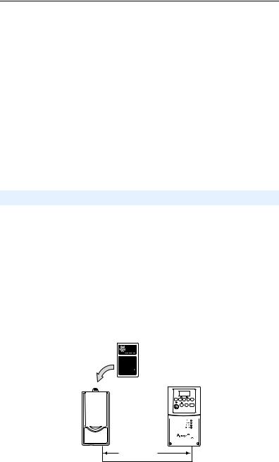
Installing the NEMA 1 WIM (22-WIM-N1)
The NEMA 1 WIM (22-WIM-N1) is installed in a HIM bezel (22-HIM-B1) that is mounted in a remote location.
1.If the HIM bezel is not mounted, refer to the HIM Bezel Installation Instructions Publication No. 22HIM-IN002… for mounting details.
2.Route the bezel cable to the drive. Connect the bezel cable to the DSI port on the bottom of the drive.
3.Install the WIM into the HIM bezel cradle (Figure 2.1).
Figure 2.1 Installing the WIM in a HIM Bezel
22-WIM-N1
(Wireless Interface Module)
22-HIM-B1
Bezel
PowerFlex 4/40/400 Drive
with Installed HIM
2 m (6.6 ft.) Bezel Cable
2-2 Installing the WIM
4.The status LED on the WIM momentarily flashes red on powerup and then flashes green to indicate it is ready to establish wireless communication with the Pocket PC or computer.
5.Establish wireless communication between the WIM and the Pocket PC or computer. For this procedure, refer to the respective section in Chapter 3 that corresponds to the drive software tool you are using:
•Using Pocket DriveExplorer for Pocket PC on page 3-2
•Using DriveExplorer/DriveExplorer Lite on page 3-10
•Using DriveExecutive on page 3-16
When communication is achieved, the WIM status LED will turn solid blue.
Installing the NEMA 4 WIM (22-WIM-N4S)
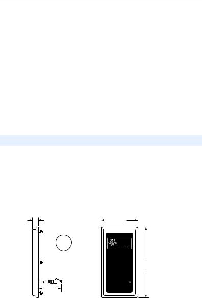
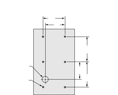
The NEMA 4 WIM (22-WIM-N4S) is designed for remote installation. Refer to Figure 2.2 for overall WIM dimensions. Choose an appropriate location to mount the NEMA 4 WIM. A cable distance greater than 3 m (10 ft.) is not CE compliant. Maximum cable length should not exceed 10 m (33 ft.).
Figure 2.2 NEMA 4 WIM Dimensions
25,0 |
|
93,0 |
|
|
|||
(0.98) |
|
|
(3.66) |
mm (in.)
180,0
(7.08)
Contains FCC ID: SNT-2XWIMNX
IC: 5450A-2XWIMNX
This device complies with Part 15 of the FCC Rules. Operation is subject to the following two conditions:
2.0 m 1) this device may not cause harmful interference, and 2) this device must accept any interference received,
including interference that may cause undesired operation
1.Drill the required hole pattern in the panel. See Figure 2.3 for dimensions.
Installing the WIM |
2-3 |
|
|
Figure 2.3 Hole Pattern for Mounting NEMA 4 WIM
67,0
(2.63)
60,0
(2.36)
|
77,0 |
|
|
(3.03) |
|
19,1 |
|
|
(0.75) |
53,5 |
|
|
(2.11) |
|
4,8 |
77,0 |
|
(3.03) |
||
(0.19) |
||
|
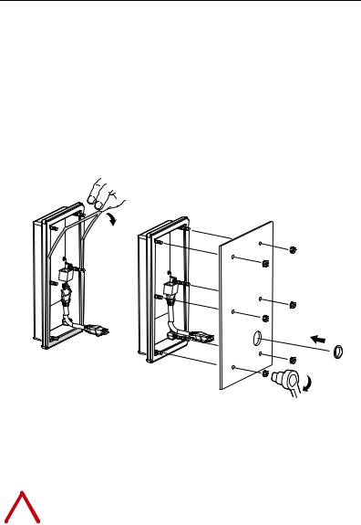
2.Peel the protective film from the gasketed surface on the back of the WIM (Figure 2.4).
3.Insert the supplied 2 m (6.6 ft.) WIM cable into the mating socket on the back of the WIM.
4.Install the supplied O-ring into the cable routing hole on the panel to protect the cable. Then route the WIM cable through the cable routing hole on the panel.
5.Align the six threaded studs of the WIM with the panel clearance holes, and place the WIM against the panel.
6.Tighten the nuts onto the six threaded studs of the WIM extending behind the panel. Recommended torque is 0.68 N-m (6.0 lb.-in.).
7.Route the WIM cable to the drive. Connect the WIM cable to the DSI port on the bottom of the drive.
8.Apply power to the drive. The status LED on the WIM momentarily flashes red on powerup and then flashes green to indicate it is ready to establish wireless communication with the Pocket PC or computer.
2-4 Installing the WIM
9.Establish wireless communication between the WIM and the Pocket PC or computer. For this procedure, refer to the respective section in Chapter 3 that corresponds to the drive software tool you are using:
•Using Pocket DriveExplorer for Pocket PC on page 3-2
•Using DriveExplorer/DriveExplorer Lite on page 3-10
•Using DriveExecutive on page 3-16
When communication is achieved, the WIM status LED will turn solid blue.
Figure 2.4 Mounting NEMA 4 WIM onto Panel


0.68 N-m
(6.0 lb.-in.)
|
|
Removing the NEMA 1 WIM (22-WIM-N1) |
|
|
|
|
|
ATTENTION: Risk of injury or equipment damage exists. If the HIM |
|
! |
bezel cable (for a bezel-mounted WIM) is disconnected from Port 2 on |
|
the bottom of the drive, the drive may fault. Determine how the drive |
|
|
|
will respond before disconnecting the cable. |
|
|
|
|
|
The drive can remain powered when removing a WIM. |
|
|
Remove the WIM from the remote-mounted HIM bezel. |
Chapter 3
Configuring the WIM
Chapter 3 provides information about configuring the WIM.
Topic |
Page |
Configuration Tools |
3-1 |
Using Pocket DriveExplorer for Pocket PC |
3-2 |
Using DriveExplorer/DriveExplorer Lite |
3-10 |
Using DriveExecutive |
3-16 |
Setting the Fault Action |
3-24 |
Enabling and Setting the Security Mode |
3-25 |
Resetting the WIM |
3-26 |
TIP: The WIM is provided ready for use. It is only necessary to configure the WIM if you want to:
•Change the default setting (0 = Fault) for Parameter 07 - [Comm Flt Action].
•Enable the security mode using Parameters 05 - [Security Mode] and 06 - [Security PIN].
•Use the RTU Master mode to monitor, configure, and control up to 32 PowerFlex 4-Class drives on a network. (See Appendix D for details.)
For a list of parameters, refer to Appendix B, WIM Parameters. For definitions of terms in this chapter, refer to the Glossary.
Configuration Tools
The WIM stores parameters and other information in its own Non-Volatile Storage (NVS). You must, therefore, access the WIM to view and edit its parameters. The following table lists tools that you can use to access the WIM and edit its parameters.
Device Type |
Tool |
Refer to… |
|
Pocket PC |
Pocket DriveExplorer for Pocket PC (version 1.01 or higher) |
Page 3-2 |
|
Laptop or |
DriveExplorer software (version 4.04 or higher) |
Page 3-10 |
|
Desktop |
|
|
|
DriveExecutive software (version 3.01 or higher) |
Page 3-16 |
||
Computer |
|||
PowerFlex HIM |
— |
||
|

3-2 Configuring the WIM
Using Pocket DriveExplorer for Pocket PC
With Pocket DriveExplorer for Pocket PC software running on a Pocket PC equipped with Bluetooth wireless technology, you can edit parameters in the WIM, connected drive, and any of the attached peripherals.
If you are unsure how to use Pocket DriveExplorer for Pocket PC, refer to the online help (select Help > Help Topics).
|
ATTENTION: Risk of injury or death exists from machine motion |
! |
when using wireless communications and software to Start/Stop/Jog, |
configure or otherwise communicate with a drive. |
Using the control bar feature in Pocket DriveExplorer for Pocket PC (version 2.01 or higher) with wireless communications may present safety hazards due to potential loss of the wireless connection. For example, if the wireless connection is interrupted after a start or jog command is initiated from the control bar, the drive cannot be stopped using the control bar until the wireless connection is restored. For this reason, it is required to always use an additional hard-wired stop circuit to disable the drive.
Establishing Wireless Communication Between the WIM and
Pocket PC
1.Launch Pocket DriveExplorer for Pocket PC from the Today Screen to create a new connection using the Connection Manager
(Figure 3.1).
Figure 3.1 Connection Manager Screen
Configuring the WIM |
3-3 |
|
|
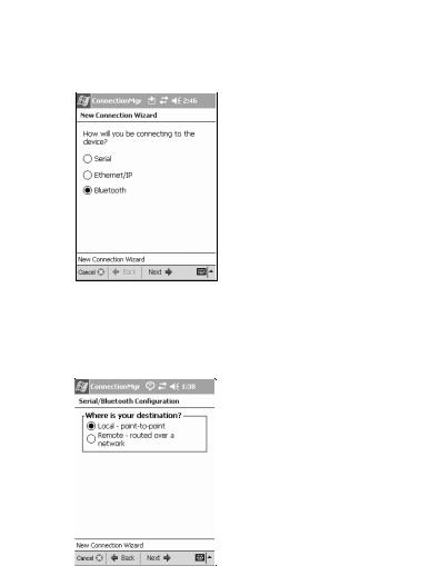
2.Select Connect > New from the menu list. The New Connection Wizard (Figure 3.2) appears.
Figure 3.2 New Connection Wizard Screen
3.Select the “Bluetooth” radio button and tap Next ->. The “Where is your destination?” screen (Figure 3.3) appears.
Figure 3.3 “Where is your destination?” Screen
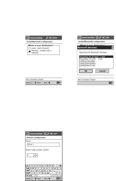
4.Select one of the radio button choices:
•Local - point-to-point: Choose “Local” if you want to connect only to a local drive using the WIM. Selecting “Local” and tapping Next -> displays the “Local Connection” screen (Figure 3.4) which requests you to name the connection for later reuse.
•Remote - routed over a network: Choose “Remote” if you want to connect to a local drive using the WIM and then route through it to a remote device on DeviceNet™ (via 22- COMM-D adapter), ControlNet™ (via 22-COMM-C adapter) or EtherNet/IP (via
3-4 Configuring the WIM
22-COMM-E adapter). Also choose “Remote” when you intend to operate the WIM in RTU Master mode. See Appendix D for details. If you select “Remote,” disregard Steps 5 through 9 and instead, go directly to Step 10 on Page 3-6 and perform sub-steps A through H.
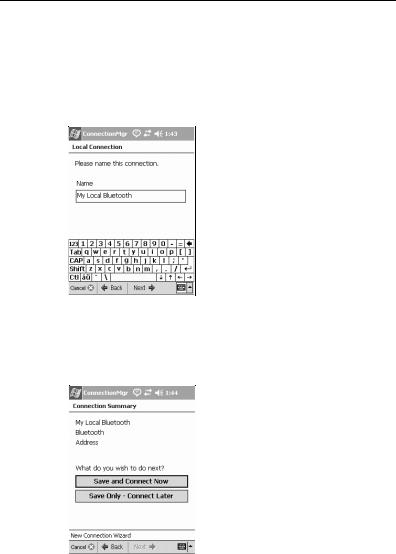
Figure 3.4 Local Connection Screen
5.Enter a name and tap Next ->. The “Connection Summary” screen (Figure 3.5) appears.
Figure 3.5 Connection Summary Screen
6.You can save the connection information and connect immediately, or save the connection for connecting later.
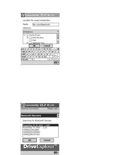
After making a selection, the “Location for saved connection” screen (Figure 3.6) appears, enabling you to navigate to a desired location on the Pocket PC to store connections.
Configuring the WIM |
3-5 |
|
|
Figure 3.6 “Location for saved connection” Screen
7.Tap OK to save the connection file and begin the connection process. The “Searching for Bluetooth Connections” screen
(Figure 3.7) appears, asking you to select a detected Bluetooth device.
Figure 3.7 Searching for Bluetooth Connections Screen
8.Select the Bluetooth device from this screen and tap OK. This screen only appears the first time you connect to this Bluetooth device. Its address is saved to the connection file. The next time you open the connection, if this same device is within range, Pocket DriveExplorer for Pocket PC will immediately connect.
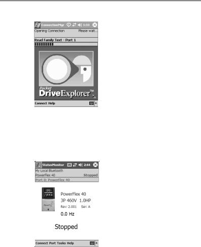
The connection process then begins (Figure 3.8).
3-6 Configuring the WIM
Figure 3.8 Opening Connection Screen
9.The status bar will update and then when connection is complete, the StatusMonitor application will launch and show the “StatusMonitor” screen (Figure 3.9) for the drive.
Figure 3.9 Drive StatusMonitor Screen
You can then select other devices from the Port menu, or other functions from the Tasks menu.
10.If you will be routing to one or more remote networked drives, you will need to perform sub-steps A through H in this step. This requires that you are able to connect to the Bluetooth card/module (cannot be done offline) because Pocket DriveExplorer for Pocket PC must interrogate the device and determine what kinds of network adapters are present.
For an example illustrating remote connection, we are using two PowerFlex 40 drives with 22-COMM-D DeviceNet adapters connected to each other using standard DeviceNet cabling.
Configuring the WIM |
3-7 |
|
|
A.With the “Where is your destination?” screen (Figure 3.10) displayed and “Remote” selected, tap Next -> to display the “Searching for Bluetooth Devices:” screen (Figure 3.11) that lists the detected Bluetooth devices.
Figure 3.10 “Where is your |
Figure 3.11 Bluetooth Browser |
|
destination?” Screen |
Screen |
|
|
|
|
|
|
|
B.Select the Bluetooth device to which you want Pocket DriveExplorer for Pocket PC to connect to, and tap OK.
C.With the Remote Configuration screen (Figure 3.12) displayed, enter a name (for this example, Drive 1) for the drive. Then set its node address (for this example, “1”) to match the node address of the 22-COMM-D DeviceNet adapter in Drive 1.
Figure 3.12 Drive 1 Remote Configuration Screen
D.Tap Next -> to display the Connection Summary screen (Figure 3.13) which shows information about this drive being connected to the network. Then tap Save and Connect Now to
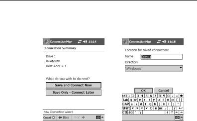
3-8 Configuring the WIM
display the “Location for saved connection” screen (Figure 3.14).
Figure 3.13 Connection Summary |
Figure 3.14 “Location for saved |
||
Screen |
connection” Screen |
||
|
|
|
|
|
|
|
|
E.Use the default name shown or enter a desired name (for this example, Drive 1). Use the default directory shown or select a different path to which the connection is saved on the Pocket PC. Then tap OK. The StatusMonitor screen for the drive appears.
F.From the Drive 1 StatusMonitor screen, select Connect > New… from the menu list. The New Connection Wizard screen appears. Then select the “Bluetooth” radio button and tap Next ->.
G.Repeat sub-steps A through E for each remaining drive on the network.
H.From the last drive’s StatusMonitor screen, select Connect > and the drive to which you want to connect to (for example, Drive 1.dfc). This establishes connection to that drive and displays its StatusMonitor screen.
Note: Using the “Remote” connection option for the WIM establishes a point-to-point connection. Therefore, you can only connect to one networked drive at a time.
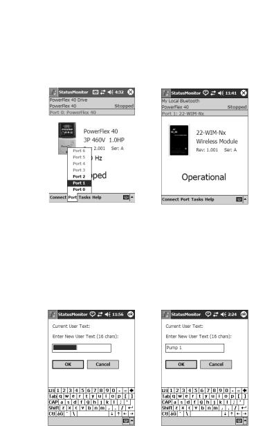
Assigning a Name for the WIM (optional)
The WIM can be assigned a custom name (up to 16 alpha-numeric characters) that represents its associated drive’s application function, such as Pump 1 or Conveyor A. After successfully establishing a custom WIM name, it replaces the default drive name (for example, PowerFlex 40 3P 460V 1.0HP) that appears in the “Searching for Bluetooth Devices” screen and will now be recognized on the network.
Configuring the WIM |
3-9 |
|
|
1.From the drive StatusMonitor screen (Figure 3.9), tap the Port menu and select the drive port to which the WIM is connected. For this example, Port 1 is selected (Figure 3.15) because the WIM is installed in the drive’s bottom RJ-45 port. The WIM StatusMonitor screen (Figure 3.16) appears.
Figure 3.15 Port Selection Screen |
Figure 3.16 WIM StatusMonitor Screen |
||
|
|
|
|
|
|
|
|
2.On the WIM StatusMonitor screen (Figure 3.16), tap the stylus on the white area above the “22-WIM-Nx” catalog number to display the User Text entry screen (Figure 3.17). In the text box, enter the desired name for the WIM (for example, Pump 1 shown in
Figure 3.18) and tap OK. The WIM StatusMonitor screen reappears with the entered name.
Figure 3.17 User Text Entry Screen Figure 3.18 Pump 1 Screen
3.For the entered name to be recognized on the network, either reset the WIM or power cycle the drive. Then re-establish wireless communication between the WIM and Pocket PC.

3-10 Configuring the WIM
Using DriveExplorer/DriveExplorer Lite
With DriveExplorer software running on a computer equipped with Bluetooth wireless technology, you can edit parameters in the WIM, connected drive, and any of the attached peripherals. DriveExplorer Lite, a free, limited-feature version of DriveExplorer, can be downloaded from http://www.ab.com/drives/driveexplorer.
If you are unsure how to use DriveExplorer or DriveExplorer Lite, refer to the online help (select Help > Help Topics).
|
ATTENTION: Risk of injury or death exists from machine motion |
! |
when using wireless communications and software to Start/Stop/Jog, |
configure or otherwise communicate with a drive. |
Using the control bar feature in DriveExplorer (version 2.01 or higher) with wireless communications may present safety hazards due to potential loss of the wireless connection. For example, if the wireless connection is interrupted after a start or jog command is initiated from the control bar, the drive cannot be stopped using the control bar until the wireless connection is restored. For this reason, it is required to always use an additional hard-wired stop circuit to disable the drive.
Establishing Wireless Communication Between the WIM and
Computer
Bluetooth wireless technology enabled cards/modules installed in a computer are typically provided with a software program to establish communication with other wireless devices. The following example procedure describes how to establish communication using the software program “My Bluetooth Places” (version 1.4.2), which was included with a specific brand Bluetooth wireless technology module. Different versions of this software and different programs may differ in appearance and procedures.
1.Launch the “My Bluetooth Places” program. The program window (Figure 3.19) will appear.
Loading...