


 Loading...
User Manual
Micro800 Discrete and Analog Expansion I/O
Catalog Numbers Bulletin 2085

Important User Information
Solid-state equipment has operational characteristics differing from those of electromechanical equipment. Safety Guidelines for the Application, Installation and Maintenance of Solid State Controls (publication SGI-1.1 available from your local Rockwell Automation sales office or online at http://www.rockwellautomation.com/literature/) describes some important differences between solid-state equipment and hard-wired electromechanical devices. Because of this difference, and also because of the wide variety of uses for solid-state equipment, all persons responsible for applying this equipment must satisfy themselves that each intended application of this equipment is acceptable.
In no event will Rockwell Automation, Inc. be responsible or liable for indirect or consequential damages resulting from the use or application of this equipment.
The examples and diagrams in this manual are included solely for illustrative purposes. Because of the many variables and requirements associated with any particular installation, Rockwell Automation, Inc. cannot assume responsibility or liability for actual use based on the examples and diagrams.
No patent liability is assumed by Rockwell Automation, Inc. with respect to use of information, circuits, equipment, or software described in this manual.
Reproduction of the contents of this manual, in whole or in part, without written permission of Rockwell Automation, Inc., is prohibited.
Throughout this manual, when necessary, we use notes to make you aware of safety considerations.
WARNING: Identifies information about practices or circumstances that can cause an explosion in a hazardous environment, which may lead to personal injury or death, property damage, or economic loss.
ATTENTION: Identifies information about practices or circumstances that can lead to personal injury or death, property damage, or economic loss. Attentions help you identify a hazard, avoid a hazard, and recognize the consequence
SHOCK HAZARD: Labels may be on or inside the equipment, for example, a drive or motor, to alert people that dangerous voltage may be present.
BURN HAZARD: Labels may be on or inside the equipment, for example, a drive or motor, to alert people that surfaces may reach dangerous temperatures.
IMPORTANT Identifies information that is critical for successful application and understanding of the product.
Allen-Bradley, Rockwell Software, Rockwell Automation, Micro800, Micro850, Connected Components Workbench, and TechConnect are trademarks of Rockwell Automation, Inc.
Trademarks not belonging to Rockwell Automation are property of their respective companies.

Preface
Who Should Use this Manual
Purpose of this Manual
Additional Resources
Read this preface to familiarize yourself with the rest of the manual. It provides information concerning:
•who should use this manual
•the purpose of this manual
•related documentation
•supporting information for Micro800™
Use this manual if you are responsible for designing, installing, programming, or troubleshooting control systems that use Micro800 controllers.
You should have a basic understanding of electrical circuitry and familiarity with relay logic. If you do not, obtain the proper training before using this product.
This manual is a reference guide for Micro800 expansion I/O modules. It describes the procedures you use to install, wire, and troubleshoot your expansion I/O. This manual:
•gives you an overview of expansion I/O features and configuration parameter
•gives you an overview of the Micro800 controller system
Refer to the Online Help provided with Connected Components Workbench™ software for more information about programming.
These documents contain additional information concerning related Rockwell Automation products.
Resource |
Description |
|
|
Micro850 Programmable Controllers Installation |
Information on mounting and wiring the |
Instructions 2080-IN007 |
Micro850 24-point Controllers |
|
|
Micro850 Programmable Controllers Installation |
Information on mounting and wiring the |
Instructions 2080-IN008 |
Micro850 48-point Controllers |
|
|
Micro800 16-point and 32-point 12/24V Sink/ |
Information on mounting and wiring the |
Source Input Modules Installation Instructions |
expansion I/O modules (2085-IQ16, 2085-IQ32T) |
2085-IN001 |
|
|
|
Micro800 Bus Terminator Module Installation |
Information on mounting and wiring the |
Instruction 2085-IN002 |
expansion I/O bus terminator (2085-ECR) |
|
|
Micro800 16-Point Sink and 16-Point Source 12/ |
Information on mounting and wiring the |
24V DC Output Modules Installation Instructions |
expansion I/O modules (2085-OV16, 2085-OB16) |
2085-IN003 |
|
|
|
Micro800 8-Point and 16-Point AC/DC Relay |
Information on mounting and wiring the |
Output Modules Installation Instructions |
expansion I/O modules (2085-OW8, 2085-OW16) |
2085-IN004 |
|
|
|
Rockwell Automation Publication 2080-UM003A-EN-E - March 2013 |
iii |

Preface
Resource |
Description |
|
|
Micro800 8-Point Input and 8-Point Output AC |
Information on mounting and wiring the |
Modules Installation Instructions 2085-IN005 |
expansion I/O modules (2085-IA8, 2085-IM8, |
|
2085-OA8) |
|
|
Micro800 4-channel and 8-channel Analog |
Information on mounting and wiring the |
Voltage/current Input and Output Modules |
expansion I/O modules (2085-IF4, 2085-IF8, |
Installation Instructions 2085-IN006 |
2085-OF4) |
|
|
Micro800 4-channel Thermocouple/RTD Input |
Information on mounting and wiring the |
Module 2085-IN007 |
expansion I/O module (2085-IRT4) |
|
|
Micro800 RS232/485 Isolated Serial Port Plug-in |
Information on mounting and wiring the |
Module Wiring Diagrams 2080-WD002 |
Micro800 RS232/485 Isolated Serial Port Plug-in |
|
Module. |
|
|
Industrial Automation Wiring and Grounding |
Provides general guidelines for installing a |
Guidelines, publication 1770-4.1 |
Rockwell Automation industrial system. |
|
|
Product Certifications website, http://ab.com |
Provides declarations of conformity, certificates, |
|
and other certification details. |
|
|
Application Considerations for Solid-State |
A description of important differences between |
Controls SGI-1.1 |
solid-state programmable controller products |
|
and hard-wired electromechanical devices. |
|
|
National Electrical Code - Published by the |
An article on wire sizes and types for grounding |
National Fire Protection Association of Boston, |
electrical equipment. |
MA. |
|
|
|
Allen-Bradley Industrial Automation Glossary |
A glossary of industrial automation terms and |
AG-7.1 |
abbreviations. |
|
|
You can view or download publications at http://www.rockwellautomation.com/ literature/. To order paper copies of technical documentation, contact your local Rockwell Automation distributor or sales representative.
You can download the latest version of Connected Components Workbench for your Micro800 at the URL below.
http://ab.rockwellautomation.com/Programmable-Controllers/Connected-
Components-Workbench-Software.
iv |
Rockwell Automation Publication 2080-UM003A-EN-E - March 2013 |

Preface
Notes:
Rockwell Automation Publication 2080-UM003A-EN-E - March 2013 |
v |

Preface
vi |
Rockwell Automation Publication 2080-UM003A-EN-E - March 2013 |

|
Table of Contents |
|
Preface |
Who Should Use this Manual . . . . . . . . . . . . . . . . . . . . . . . . . . . . . . . . . . . . . . |
iii |
|
Purpose of this Manual . . . . . . . . . . . . . . . . . . . . . . . . . . . . . . . . . . . . . . . . . . . . |
iii |
|
Additional Resources . . . . . . . . . . . . . . . . . . . . . . . . . . . . . . . . . . . . . . . . . . . . . . |
iii |
|
Chapter 1 |
|
Hardware Features |
Micro800 Expansion I/O Modules . . . . . . . . . . . . . . . . . . . . . . . . . . . . . . . . . |
. 1 |
|
Hardware Features . . . . . . . . . . . . . . . . . . . . . . . . . . . . . . . . . . . . . . . . . . . . . . . . |
. 2 |
|
Summary . . . . . . . . . . . . . . . . . . . . . . . . . . . . . . . . . . . . . . . . . . . . . . . . . . . . . . . . . |
. 4 |
|
Chapter 2 |
|
Discrete and Analog Expansion |
Overview . . . . . . . . . . . . . . . . . . . . . . . . . . . . . . . . . . . . . . . . . . . . . . . . . . . . . . . . . |
. 5 |
I/O Features |
Discrete Expansion I/O Features . . . . . . . . . . . . . . . . . . . . . . . . . . . . . . . . . . . |
. 5 |
|
Discrete Input. . . . . . . . . . . . . . . . . . . . . . . . . . . . . . . . . . . . . . . . . . . . . . . . . |
. 5 |
|
Discrete Output. . . . . . . . . . . . . . . . . . . . . . . . . . . . . . . . . . . . . . . . . . . . . . . |
. 6 |
|
Analog Expansion I/O Features . . . . . . . . . . . . . . . . . . . . . . . . . . . . . . . . . . . . |
. 6 |
|
Analog Input and Output . . . . . . . . . . . . . . . . . . . . . . . . . . . . . . . . . . . . . . |
. 7 |
|
Specialty Module 2085-IRT4 Temperature Input Module . . . . . . . |
11 |
|
Summary . . . . . . . . . . . . . . . . . . . . . . . . . . . . . . . . . . . . . . . . . . . . . . . . . . . . . . . . |
14 |
|
Chapter 3 |
|
Wiring Connections |
Input/Output Wiring . . . . . . . . . . . . . . . . . . . . . . . . . . . . . . . . . . . . . . . . . . . . |
15 |
|
Wiring Options for the 2085-IQ32T Module. . . . . . . . . . . . . . . . . . . |
21 |
|
Summary . . . . . . . . . . . . . . . . . . . . . . . . . . . . . . . . . . . . . . . . . . . . . . . . . . . . . . . . |
24 |
|
Chapter 4 |
|
Install Your Micro800 |
Mount the Module . . . . . . . . . . . . . . . . . . . . . . . . . . . . . . . . . . . . . . . . . . . . . . . |
25 |
Expansion I/O |
Module Spacing . . . . . . . . . . . . . . . . . . . . . . . . . . . . . . . . . . . . . . . . . . . . . . |
25 |
|
DIN Rail Mounting . . . . . . . . . . . . . . . . . . . . . . . . . . . . . . . . . . . . . . . . . . |
26 |
|
Panel Mounting . . . . . . . . . . . . . . . . . . . . . . . . . . . . . . . . . . . . . . . . . . . . . . |
27 |
|
System Assembly . . . . . . . . . . . . . . . . . . . . . . . . . . . . . . . . . . . . . . . . . . . . . . . . . |
27 |
|
Summary . . . . . . . . . . . . . . . . . . . . . . . . . . . . . . . . . . . . . . . . . . . . . . . . . . . . . . . . |
28 |
Configure Your Expansion I/O
Module
Chapter 5
Overview . . . . . . . . . . . . . . . . . . . . . . . . . . . . . . . . . . . . . . . . . . . . . . . . . . . . . . . . 29
Add an Expansion I/O . . . . . . . . . . . . . . . . . . . . . . . . . . . . . . . . . . . . . . . . . . . 29 Edit Expansion I/O Configuration . . . . . . . . . . . . . . . . . . . . . . . . . . . . . . . . 32
Delete and Replace an Expansion I/O Configuration . . . . . . . . . . . . 42
Build, Save, Download a Project with Expansion I/O Configuration. . 44 Summary . . . . . . . . . . . . . . . . . . . . . . . . . . . . . . . . . . . . . . . . . . . . . . . . . . . . . . . . 44
|
Appendix A |
|
Specifications |
Discrete Expansion I/O. . . . . . . . . . . . . . . . . . . . . . . . . . . . . . . . . . . . . . . . . . . |
45 |
|
Analog Expansion I/O. . . . . . . . . . . . . . . . . . . . . . . . . . . . . . . . . . . . . . . . . . . . |
50 |
|
Specialty Expansion I/O . . . . . . . . . . . . . . . . . . . . . . . . . . . . . . . . . . . . . . . . . . |
52 |
Rockwell Automation Publication 2080-UM003A-EN-E - March 2013 |
vii |

Table of Contents
Appendix B
Expansion I/O Data Mapping Discrete I/O Data Mapping . . . . . . . . . . . . . . . . . . . . . . . . . . . . . . . . . . . . . . . 57
Analog I/O Data Mapping . . . . . . . . . . . . . . . . . . . . . . . . . . . . . . . . . . . . . . . . 58
Specialty I/O Data Mapping. . . . . . . . . . . . . . . . . . . . . . . . . . . . . . . . . . . 61
Calibration of Analog Modules . . . . . . . . . . . . . . . . . . . . . . . . . . . . . . . . . . . . 63
Specifications . . . . . . . . . . . . . . . . . . . . . . . . . . . . . . . . . . . . . . . . . . . . . . . . . . . . 63
Index
viii |
Rockwell Automation Publication 2080-UM003A-EN-E - March 2013 |
Chapter 1
Hardware Features
Micro800 Expansion I/O
Modules
Micro850 controllers support a range of discrete and analog expansion I/O modules. You can attach up to four expansion I/O modules, in any combination, to a Micro850 controller, as long as the total number of embedded, plug-in, and expansion discrete I/O points is less than or equal to 132.
The following expansion I/O modules are compatible with Micro850 controllers:
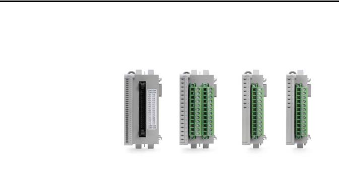
Micro800 Expansion I/O Modules
Catalog |
Type |
Description |
|
|
|
2085-IA8 |
Discrete |
8-point, 120V AC input |
|
|
|
2085-IM8 |
Discrete |
8-point, 240V AC input |
|
|
|
2085-OA8 |
Discrete |
8-point, 120/240V AC Triac Output |
|
|
|
2085-IQ16 |
Discrete |
16-point, 12/24V Sink/Source Input |
|
|
|
2085-IQ32T |
Discrete |
32-point, 12/24V Sink/Source Input |
|
|
|
2085-OV16 |
Discrete |
16-point, 12/24V DC Sink Transistor Output |
|
|
|
2085-OB16 |
Discrete |
16-point, 12/24V DC Source Transistor Output |
|
|
|
2085-OW8 |
Discrete |
8-point, AC/DC Relay Output |
|
|
|
2085-OW16 |
Discrete |
16-point, AC/DC Relay Output |
|
|
|
2085-IF4 |
Analog |
4-channel, 14-bit isolated(1) voltage/current input |
2085-IF8 |
Analog |
8-channel, 14-bit isolated(1) voltage/current input |
Rockwell Automation Publication 2080-UM003A-EN-E - March 2013 |
1 |
Chapter 1 Hardware Features
Micro800 Expansion I/O Modules
Catalog |
Type |
Description |
|
|
|
|
|
2085-OF4 |
Analog |
4-channel, 12-bit isolated(1) |
voltage/current output |
2085-IRT4 |
Analog |
4-channel, 16-bit isolated(1) |
RTD and Thermocouple input module |
2085-ECR |
Terminator |
2085 bus terminator |
|
|
|
|
|
(1) Refers to isolation from field side wiring to controller, not channel-to-channel isolation.
Hardware Features
The bus terminator, 2085-ECR, serves as an end cap and terminates the end of the serial communication bus. It is required whenever an expansion I/O module is connected to the controller and should be connected to the last expansion I/O module in the system.
Micro850 expansion I/O modules come as a single-width (87 x 28 x 90 mm, HxWxD) or double-width (87 x 46 x 90 mm, HxWxD) form factor. See specifications for Expansion I/O on page 240 for information on module dimensions.
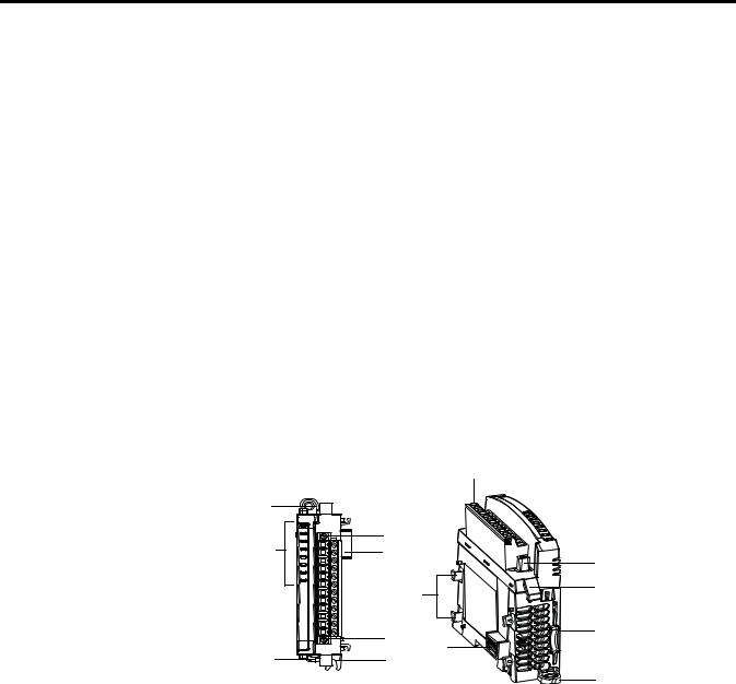
Single-width Expansion I/O
2085-OW8 shown |
|
|
2 |
|
|
|
|
1 |
|
|
|
8 |
3 |
|
|
6 |
|
3 |
|
|
|
|
|
|
7 |
|
4 |
|
|
|
|
|
3 |
|
5 |
|
6 |
|
|
|
1 |
|
|
5 |
|
|
|
45307 |
|
45308 |
1 |
|
|
Front view |
Right top view |
|
2 |
Rockwell Automation Publication 2080-UM003A-EN-E - March 2013 |
Hardware Features |
Chapter 1 |
|
|
Double-width Expansion I/O |
|
|
|
2085-OW16 shown |
|
2 |
|
|
|
|
|
1 |
|
|
|
|
3 |
|
|
|
6 |
|
3 |
|
|
|
4 |
8 |
|
|
|
|
7 |
|
|
|
|
|
5 |
|
3 |
6 |
|
9 |
1 |
|
1 |
45296 |
|
45297 |
|
|
|
||
|
Front view |
|
|
Right top view |
|
Module Description |
|
|
|
|
|
|
|
|
|
|
|
|
Description |
|
|
|
Description |
|
|
|
|
|
|
1 |
Mounting screw hole / mounting foot |
|
6 |
|
Bus connector (male/female) |
|
|
|
|
|
|
2 |
Removable Terminal Block (RTB)(1) |
|
7 |
|
Latch hooks |
3 |
RTB hold down screws |
|
8 |
|
I/O status LED |
|
|
|
|
|
|
4 |
Cable grip |
|
9 |
|
DIN rail mounting latch |
|
|
|
|
|
|
5 |
Module interconnect latch |
|
|
|
|
|
|
|
|
|
|
(1)The removable terminal block has slots for mechanical keying, to prevent inadvertently making the wrong wire connections to your module. Expansion I/O modules are shipped with keys.
2085-IQ32T Hardware Features
1 |
2 |
|
|
|
3 |
6 |
2 |
3 |
4 |
|
8
7


 5 6
5 6 


1
9 |
Right top view |
45927 |
Front view
Rockwell Automation Publication 2080-UM003A-EN-E - March 2013 |
3 |

Chapter 1 Hardware Features
2085-IQ32T Hardware Components
|
Description |
|
|
Description |
|
|
|
|
|
1 |
Mounting screw hole / mounting foot |
|
6 |
bus connector (male and female) |
|
|
|
|
|
2 |
Connector |
|
7 |
latch hooks |
|
|
|
|
|
3 |
Connector retaining arm |
|
8 |
I/O status LEDs |
|
|
|
|
|
4 |
Cable grip |
|
9 |
DIN rail mounting latch |
|
|
|
|
|
5 |
Module interconnecting latch |
|
|
|
|
|
|
|
|
Summary
This chapter included a brief introduction to the different analog and discrete Micro800 expansion I/O modules and their hardware features.
4 |
Rockwell Automation Publication 2080-UM003A-EN-E - March 2013 |

Chapter 2
Overview
Discrete Expansion I/O
Features
Discrete and Analog Expansion I/O Features
This section includes a brief description of the different features and configuration parameters for the analog and discrete Micro800 expansion I/O modules. It covers the following topics.
Topic |
Page |
|
|
Discrete Expansion I/O Features |
5 |
|
|
Discrete Input |
5 |
|
|
Discrete Output |
6 |
|
|
Analog Expansion I/O Features |
6 |
|
|
Analog Input and Output |
7 |
|
|
Specialty Module 2085-IRT4 Temperature Input Module |
11 |
|
|
Micro800 discrete expansion I/O modules are input/output modules that provide On/Off detection and actuation.
Module Information
The Connected Components Workbench programming software makes it easy to configure the modules as most module features can be enabled or disabled through the device configuration portion of the software. You can also use the software to check any expansion I/O module in the system to retrieve:
•hardware revision information
•vendor ID
•module information
Channel Status Indicator Information
The discrete expansion I/O modules have yellow status indicators for each input/ output point which indicates the On/Off state of the point.
Discrete Input
Discrete input modules interface to sensing devices and detect whether they are On or Off. These modules convert AC or DC On/Off signals from user devices to appropriate logic level for use within the processor.
Rockwell Automation Publication 2080-UM003A-EN-E - March 2013 |
5 |

Chapter 2 Discrete and Analog Expansion I/O Features
Analog Expansion I/O
Features
The 2085-IA8, 2085-IM8, 2085-IQ16 and 2085-IQ32T modules update the controller with new data whenever an input point transitions from On to Off and Off to On.
On to Off and Off to On filter times can be adjusted through the Connected Components Workbench software. These filters improve noise immunity within a signal. A larger filter value affects the length of delay times for signals from these modules.
You can select from a series of operational ranges for each channel. The range designates the minimum and maximum signals that are detectable by the module.
Discrete Output
Output modules may be used to drive a variety of output devices. Typical output devices compatible with the outputs include:
•motor starters
•solenoids
•indicators
Follow these guidelines when designing a system.
•Make sure that the outputs can supply the necessary surge and continuous current for proper operation. (See Specifications on page 45 for more information.)
•Make sure that the surge and continuous current are not exceeded. Damage to the module could result. When sizing output loads, check the documentation supplied with the output device for the surge and continuous current needed to operate the device. The Micro800 standard digital outputs are capable of directly driving the Micro800 standard digital inputs.
TIP |
User-configurable options are not available in Connected Components |
|
Workbench for discrete output modules. |
IMPORTANT On controller minor and major fault, all output channels are de-energized.
This section pertains to the following Micro800 analog expansion I/O modules:
Micro800 Expansion I/O Modules
Catalog |
Type |
Description |
|
|
|
|
|
2085-IF4 |
Analog |
4-channel, 14-bit isolated(1) |
voltage/current input |
2085-IF8 |
Analog |
8-channel, 14-bit isolated(1) |
voltage/current input |
6 |
Rockwell Automation Publication 2080-UM003A-EN-E - March 2013 |

Discrete and Analog Expansion I/O Features Chapter 2
Micro800 Expansion I/O Modules
Catalog |
Type |
Description |
|
|
|
|
|
2085-OF4 |
Analog |
4-channel, 12-bit isolated(1) |
voltage/current output |
2085-IRT4 |
Analog |
4-channel, 16-bit isolated(1) |
RTD and Thermocouple input module |
2085-ECR |
Terminator |
2085 bus terminator |
|
|
|
|
|
(1) Refers to isolation from field side wiring to controller, not channel-to-channel isolation.
Analog expansion I/O modules are interface modules that convert analog signals to digital values for inputs and convert digital values to analog signals for outputs. Controllers can then use these signals for control purposes.
Analog Input and Output
Input/Output Types and Ranges
The 2085-IF4 and 2085-IF8 modules support four and eight input channels, respectively, while the 2085-OF4 supports four output channels. Each of the channels can be configured as current or voltage input/output, with current mode as default configuration.
Input/Output Type/Range for 2085-IF4, 2085-IF8, and 2085-OF4
Module |
Input/Output Type/Range |
|
|
|
|
2085-IF4 |
0…20 mA |
|
|
4…20 mA (default) |
|
2085-IF8 |
||
-10…10 V |
||
|
0…10 V |
|
2085-OF4 |
||
|
||
|
|
To use an input or output as a current or voltage device, you must:
•wire the input/output connector for the correct input/output type (see Input/Output Wiring on page 15)
•configure the input/output as current or voltage through Connected Components Workbench (see Configure Your Expansion I/O Module on page 29)
Data formats
This parameter configures each channel to present analog data in any of the following formats:
•Raw/Proportional Data –The value presented to the controller is proportional to the selected input and scaled into the maximum data range allowed by the bit resolution of the A/D converter. For example, the data value range for a ±10V DC user input is -32,768…32,767, which covers the full-scale range of -10.5…10.5V. See Valid Range of the Data Formats for 2085-IF4, 2085-IF8, and 2085-OF4 on page 8.
Rockwell Automation Publication 2080-UM003A-EN-E - March 2013 |
7 |

Chapter 2 Discrete and Analog Expansion I/O Features
•Engineering Units – The module scales the analog input data to the actual current or voltage values for the selected input range. The resolution of the engineering units is 0.001V or 0.001 mA per count.
•Percent Range – The input data is presented as a percentage of the normal operating range. For example, 0V…10V DC equals 0…100%. The amount over and under the normal operating range (the full-scale range) is also supported.
Valid Range of the Data Formats for 2085-IF4, 2085-IF8, and 2085-OF4
The valid range of each Data Format corresponds to the full range of each Type/
Range (or normal range). For example, the full range of 0…20 mA is 0…21 mA.
Valid Range of the 2085-IF4 and 2085-IF8 Data Formats
Data Format |
|
Type/Range |
|
|
|
|
|
|
|
|
0…20 mA(4) |
4…20 mA(4) |
-10…10V(4) |
0…10 V(4) |
Raw/Proportional Data(1) |
|
-32768…32767 |
|
|
Engineering Units(2) |
0…21000 |
3200…21000 |
-10500…10500 |
-500…10500 |
Percent Range(3) |
0…10500 |
-500…10625 |
Not supported |
-500…10500 |
(1)See Convert Analog Value to Data Format Value on page 9.
(2)The resolution is 0.001V or 0.001 mA per count. For example, 9999 here means 9.999V or 9.999 mA (or 9999 x 0.001).
(3)The resolution is 0.01% per count. For example, 9999 here means 99.99% (or 9999 x 0.01%). See Convert Analog Value to Data Format Value on page 9
(4)The full range value of:
a.0…20 mA is 0…21 mA
b.4 to 20 mA is 3.2…21 mA
c.-10…10V is -10.5…10.5V
d.0…10V is -0.5…10.5V
Valid Range of the 2085-OF4 Data Formats
Data Format |
|
Type/Range |
|
|
|
|
|
|
|
|
0…20 mA(4) |
4…20 mA(4) |
-10…10V(4) |
0…10V(4) |
Raw/Proportional |
|
-32768…32767 |
|
|
Data(1) |
|
|
|
|
Engineering Units(2) |
0…21000 |
3200…21000 |
-10500…10500 |
0…10500 |
Percent Range(3) |
0…10500 |
-500…10625 |
Not supported |
0…10500 |
(1)See Convert Analog Value to Data Format Value on page 9.
(2)The resolution is 0.001V or 0.001 mA per count. For example, 9999 here means 9.999V or 9.999 mA (or 9999 x 0.001.
(3)The resolution is 0.01% per count. For example, 9999 here means 99.99% (or 9999 x 0.01%). See Convert Analog Value to Data Format Value on page 9.
(4)The full range value of:
a.0…20 mA is 0…21 mA
b.4…20 mA is 3.2…21 mA
c.-10…10V is -10.5…10.5V
d.0…10V is 0…10.5V
8 |
Rockwell Automation Publication 2080-UM003A-EN-E - March 2013 |

Discrete and Analog Expansion I/O Features |
Chapter 2 |
|
|
Convert Analog Value to Data Format Value
The formula for converting an analog value x to a data format value y (or conversely, deriving data format value y to analog value x) is as follows:
Y = ((X - Minimum Value of X Range)*(Range of Y)/(Range of X)) +
(Minimum Value of Y Range)
Example 1:
Find the analog value Y of Type/Range 4…20 mA when the Raw/Proportional
Data X is -20000.
Given:
X = -20000
Minimum value of X Range = -32768
Range of X = 32767 - (-32768) = 65535
Range of Y = 21- 3.2 = 17.8
Minimum value of Y Range = 3.2
Using the conversion formula:
Y = (-20000 - (-32768))*17.8/65535 + (3.2) = 6.668 mA
Example 2:
Find the Raw/Proportional value (Y) of 10 mA (X) for type/range 4…20 mA.
Given:
X = 10 mA
Minimum Value of X Range = 3.2 mA (Minimum value of 4…20 mA)
Range of X = 21 - 3.2 = 17.8 mA (Range of 4…20 mA)
Range of Y = 32767 - (-32768) = 65535 (Range of Raw/Proportional
Data)
Minimum Value of Y Range = -32768. (Min value of Raw/Proportional
Data)
Using the conversion formula:
Y = -7732.15 (decimals are not displayed)
Input Filter
For the input modules, 2085-IF4 and 2085-IF8, the input filter parameter lets you specify the frequency filter type for each channel. Frequency filter type affects noise rejection, as explained below. Select a frequency filter type considering acceptable noise and response time.
Through the Connected Components Workbench software, you can configure input filter as:
•50/60Hz Rejection (default)
•No Filter
•2-Point Moving Average
Rockwell Automation Publication 2080-UM003A-EN-E - March 2013 |
9 |

Chapter 2 Discrete and Analog Expansion I/O Features
•4-Point Moving Average
•8-Point Moving Average
Noise Rejection
The input modules use a digital filter that provides noise rejection for the input signals.
The moving average filter reduces the high frequencies and random white noise while keeping an optimal step response. (See specifications for Analog Expansion I/O on page 50 for minimum and maximum response times.)
Normal Mode Rejection is better than 40 dB, while Common Mode Rejection is better than 60 dB @ 50/60 Hz, with the 50/60 Hz rejection filters selected. The modules perform well in the presence of common mode noise as long as the signals applied to the user plus and minus input terminals do not exceed the common mode voltage rating (±10 V) of the modules. Improper earth ground may be a source of common mode noise.
Process Level Alarms
Process level alarms alert you when the module has exceeded configured high and low limits for each channel (for input modules, it provides additional high-high and low-low alarms). When the channel input or output goes below a low alarm or above a high alarm, a bit is set in the status words. All Alarm Status bits can be read individually or read through the Channel Status Byte.
For the output module, 2085-OF4, it is possible to latch the alarm status bit when the latch configuration is enabled.
You can configure each channel alarm individually.
Clamping Limits and Alarm
For the output module, 2085-OF4, clamping limits the output from the analog module to remain within a range configured by the controller, even when the controller commands an output outside that range. This safety feature sets a high clamp and a low clamp. Once clamps are determined for a module, any data received from the controller that exceeds those clamps transitions the output to that limit but not beyond the clamp value. It also sets the alarm status bit when the alarm is enabled. It is also possible to latch the alarm status bit when the latch configuration is enabled.
For example, an application may set the high clamp on a module for 8V and the low clamp for -8V. If a controller sends a value corresponding to 9V to the module, the module will only apply 8V to its screw terminals.
You can configure the clamp limit (high/low clamp), the associated alarm, and its latching configuration on a per channel basis.
10 |
Rockwell Automation Publication 2080-UM003A-EN-E - March 2013 |

Discrete and Analog Expansion I/O Features |
Chapter 2 |
|
|
The following table shows the default values of the High/Low Clamps (in the order of low clamp value followed by the high clamp value) for the respective type/range when they are first enabled. You can change these values (within their full range) according to your application.
Default Range of High Clamp/Low Clamp Values
Data Format |
0…20 mA |
4…20 mA |
-10…10V |
0…10V |
|
|
|
|
|
Raw/Proportional Data |
-32768, 29647 |
-29822, 29086 |
-31207, 31207 |
-32768, 29647 |
|
|
|
|
|
Engineering Units |
0, 20000 |
4000, 20000 |
-10000, 10000 |
0, 10000 |
|
|
|
|
|
Percent Range |
0, 10000 |
0, 10000 |
Not supported |
0, 10000 |
|
|
|
|
|
Specialty Module 2085-IRT4 Temperature Input Module
The 2085-IRT4 module lets you configure a sensor type for each of four input channels that linearizes analog signal into a temperature value.
Sensor Type
The following Thermocouple and RTD sensor types are supported by the 2085-IRT4 expansion I/O module.
Supported Thermocouple Types and mV Range
Sensor Range |
Range |
|
|
|
|
B |
300…1800 °C |
(572…3272 °F) |
|
|
|
C |
0…2315 °C |
(32…4199 °F) |
|
|
|
E |
-270…1000 °C |
(-454…1832 °F) |
|
|
|
J |
-210…1200 °C |
(-346…2192 °F) |
|
|
|
K |
-270…1372 °C |
(-454…2502 °F) |
|
|
|
TXK/XK (L) |
-200…800 °C |
(-328…1472 °F) |
|
|
|
N |
-270…1300 °C |
(-454…2372 °F) |
|
|
|
R |
-50…1768 °C |
(-58…3214 °F) |
|
|
|
S |
-50…1768 °C |
(-58…3214 °F) |
|
|
|
T |
-270…400 °C |
(-454…752 °F) |
|
|
|
mV |
0…100 mV |
|
|
|
|
Supported RTD Types and Ohms Range
Sensor Range |
Range |
|
|
|
|
|
|
100 |
Ω Pt α = 0.00385 Euro |
-200…870 °C |
(-328…1598 °F) |
|
|
|
|
200 |
Ω Pt α = 0.00385 Euro |
-200…400 °C |
(-328…752 °F) |
|
|
|
|
100 |
Ω Pt α = 0.003916 U.S |
-200…630 °C |
(-328…1166 °F) |
|
|
|
|
200 |
Ω Pt α = 0.003916 U.S. |
-200…400 °C |
(-328…752 °F) |
|
|
|
|
Rockwell Automation Publication 2080-UM003A-EN-E - March 2013 |
11 |

Chapter 2 Discrete and Analog Expansion I/O Features
Supported RTD Types and Ohms Range
Sensor Range |
Range |
|
|
|
|
100 Ω Nickel 618 |
-60…250 °C |
(-76…482 °F) |
|
|
|
200 Ω Nickel 618 |
-60…200 °C |
(-76…392 °F) |
|
|
|
120 Ω Nickel 672 |
-80…260 °C |
(-112…500 °F) |
|
|
|
10 Ω Copper 427 |
-200…260 °C |
(-328…500 °F) |
|
|
|
Ohms |
0…500 Ohms |
|
|
|
|
Data format
You can configure the following data formats for channels 0…3 through the Connected Components Workbench software.
•Engineering Units x 1 – If you select engineering units x 1 as the data format for a Thermocouple and RTD input, the module scales input data to the actual temperature values for the selected Thermocouple/RTD type per Thermocouple/RTD standard. It expresses temperatures in 0.1 °C/° F units. For resistance inputs, the module expresses resistance in 0.1 ohm per count. For mV inputs, the module expresses it in 0.01 mV per count.
•Engineering Units x 10 – For a Thermocouple or RTD input, the module scales input data to the actual temperature values for the selected Thermocouple/RTD type per Thermocouple/RTD standard. With this format, the module expresses temperatures in 1 °C/° F units. For resistance inputs, the module expresses resistance in 1 ohm per count. For mV inputs, the module expresses it in 0.1 mV per count.
•Raw/Proportional Data Format – The value presented to the controller is proportional to the selected input and scaled into the maximum data range allowed by the bit resolution of the A/D converter. For example, the full data value range for a thermocouple type B 300...1800 °C is mapped to -32768...32767. See Convert Analog Value to Data Format Value on page 13 for the conversion method.
•Percent Range – The input data is presented as a percentage of the normal operating range. For example, 0…100 mV equals 0…100% or 300..1800 °C equals 0...100% for thermocouple type B sensor. See Convert Analog Value to Data Format Value on page 13 for the conversion method.
Valid Range of the Data Formats for 2085-IRT4
The following table shows the valid range of the Data Format versus the Data Type/Range for channels 0…3.
12 |
Rockwell Automation Publication 2080-UM003A-EN-E - March 2013 |
Discrete and Analog Expansion I/O Features |
Chapter 2 |
|
|
Valid Range of the 2085-IRT4 Data Formats
Data Format |
Sensor Type – Temperature |
|
Sensor Type |
Sensor Type |
|
|
(10 Thermocouples, 8 RTDs) |
|
0…100 mV |
0…500 ohms |
|
|
|
|
|
|
|
Raw/Proportional Data(1) |
|
-32768…32767 |
|
||
Engineering Units x 1 |
Temperature Value(3) |
(°C/°F) |
|
0…10000(5) |
0…5000(7) |
Engineering Units x 10 |
Temperature Value(4) |
(°C/°F) |
|
0…1000(6) |
0…500(8) |
Percent Range(2) |
|
|
0…10000 |
|
|
(1)See Convert Analog Value to Data Format Value on page 13.
(2)The resolution is 0.01% per count. For example, 9999 here means 99.99% (or 9999 x 0.01%). See Convert Analog Value to Data Format Value on page 13 for the conversion method.
(3)The resolution is 0.1 °C/°F per count. For example, 999 here means 99.9 °C/°F (or 999 x 0.1 °C/°F). The range depends on the selected sensor type.
(4)The resolution is 1 °C/°F per count. For example, 999 here means 999 °C/°F (or 999 x 1 °C/°F). The range depends on the selected sensor type.
(5)The resolution is 0.01 mV per count. For example, 9999 here means 99.99 mV (or 9999 x 0.01 mV).
(6)The resolution is 0.1 mV per count. For example, 999 here means 99.9 mV (or 999 x 0.1 mV).
(7)The resolution is 0.1 ohm per count. For example, 4999 here means 499.9 ohm (or 4999 x 0.1 ohm).
(8)The resolution is 1 ohm per count. For example, 499 here means 499 ohm (or 499 x 1 ohm).
Convert Analog Value to Data Format Value
The formula for converting an analog value x to a data format value y, or converting data format value y to analog value x, is as follows:
Y = ((X - Minimum Value of X Range)*(Range of Y)/(Range of X)) +
(Minimum Value of Y Range)
Example:
Find the temperature value Y of thermocouple type K when the Raw/
Proportional Data X is -20000.
Given:
X = -20000 (Raw/Proportional Value)
Minimum value of X Range = -32768 (Minimum value of Raw/
Proportional Data)
Range of X = 32767 - (-32768) = 65535 (Range of Raw/Proportional
Data)
Range of Y = 1372 - (-270) = 1642 (Range of Thermocouple K in °C)
Minimum value of Y Range = -270 °C (Minimum value of Thermocouple
K)
Then:
Y = (-20000 - (-32768))*1642/65535 + (-270 °C) = 49.9 °C
Rockwell Automation Publication 2080-UM003A-EN-E - March 2013 |
13 |

Chapter 2 Discrete and Analog Expansion I/O Features
Summary
Temperature Units
Temperature value can be set to °C (default) or °F.
Open circuit response
This parameter defines the response to be taken by the module during an open circuit.
•Upscale – Sets input to full upper scale value of channel data word. The full-scale value is determined by the selected input type, data format, and scaling.
•Downscale – Sets input to full lower scale value of channel data word. The low scale value is determined by the selected input type, data format, and scaling.
•Hold Last State – Sets input to last input value.
•Zero – Sets input to 0 to force the channel data word to 0.
Filter frequency
The 2085-IRT4 module uses a digital filter that provides noise rejection for the input signals. The filter is set by default at 4 Hz. The digital filter provides
-3 dB (50% amplitude) attenuation at a filter frequency of 4 Hz.
The -3 dB frequency is the filter cut-off frequency. The cut-off frequency is defined as the point on the frequency response curve where frequency components of the input signal are passed with 3 dB of attenuation. All input frequency components at or below the cut-off frequency are passed by the digital filter with less than 3 dB of attenuation. All frequency components above the cutoff frequency are increasingly attenuated.
The cut-off frequency for each channel is defined by its filter frequency selection and is equal to the filter frequency setting. Choose a filter frequency so that your fastest changing signal is below that of the filter’s cut-off frequency. The cut-off frequency should not be confused with the update time. The cut-off frequency relates to how the digital filter attenuates frequency components of the input signal. The update time defines the rate at which an input channel is scanned and its channel data word is updated.
A lower filter frequency provides a better noise rejection, but it also increases the update time. Conversely, a higher filter frequency provides a faster update time, but it decreases the noise rejection and effective resolution.
TIP |
For quickstart instructions on how to add, configure, delete and replace |
|
your expansion I/O module, see Configure Your Expansion I/O Module. |
This chapter discussed the features of the analog and discrete Micro800 expansion I/O modules.
14 |
Rockwell Automation Publication 2080-UM003A-EN-E - March 2013 |
Chapter 3
Wiring Connections
Input/Output Wiring
In solid-state control systems, grounding and wire routing helps limit the effects of noise due to electromagnetic interference (EMI).
ATTENTION: Do not wire more than 2 conductors on any single terminal.
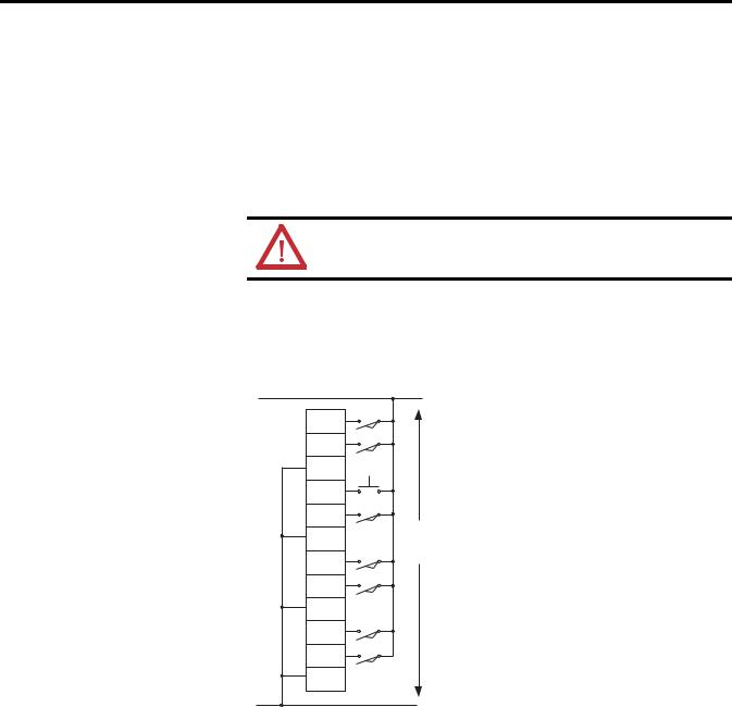
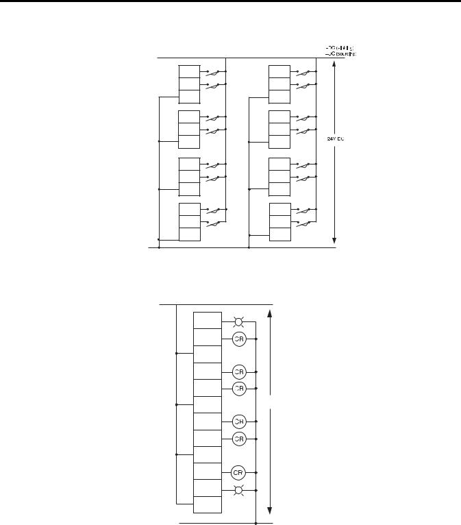
Basic wiring of devices to the expansion I/O modules are shown below.
2085-IA8 or 2085-IM8
L1
I-00
I-01
COM
I-02
I-03
120V AC (2085-IA8)
COM
240V AC (2085-IM8)
I-04
I-05
COM
I-06
I-07
COM
L2 45313
Rockwell Automation Publication 2080-UM003A-EN-E - March 2013 |
15 |
Chapter 3 Wiring Connections
2085-IQ16
I-00 |
I-08 |
|
|
I-01 |
I-09 |
|
|
COM0 |
COM1 |
|
|
I-02 |
I-10 |
|
|
I-03 |
I-11 |
|
|
COM0 |
COM1 |
|
|
I-04 |
I-12 |
|
|
I-05 |
I-13 |
|
|
COM0 |
COM1 |
|
|
I-06 |
I-14 |
|
|
I-07 |
I-15 |
|
|
COM0 |
COM1 |
|
|
Terminal Block 1 |
Terminal Block 2 |
-DC (sinking) |
45299 |
+DC (sourcing) |
|
2085-OA8
L1
O-00
O-01
L1
O-02
O-03
120V / 240V AC
L1
O-04
O-05
L1
O-06
O-07
L1
45314
L2
16 |
Rockwell Automation Publication 2080-UM003A-EN-E - March 2013 |
Loading...