


 Loading...
ControlNet
Adapter
22-COMM-C FRN 1.xxx
User Manual
Important User Information
Solid state equipment has operational characteristics differing from those of electromechanical equipment. Safety Guidelines for the Application, Installation and Maintenance of Solid State Controls (Publication SGI-1.1 available from your local Rockwell Automation sales office or online at http://www.rockwellautomation.com/ literature) describes some important differences between solid state equipment and hard-wired electromechanical devices. Because of this difference, and also because of the wide variety of uses for solid state equipment, all persons responsible for applying this equipment must satisfy themselves that each intended application of this equipment is acceptable.
In no event will Rockwell Automation, Inc. be responsible or liable for indirect or consequential damages resulting from the use or application of this equipment.
The examples and diagrams in this manual are included solely for illustrative purposes. Because of the many variables and requirements associated with any particular installation, Rockwell Automation, Inc. cannot assume responsibility or liability for actual use based on the examples and diagrams.
No patent liability is assumed by Rockwell Automation, Inc. with respect to use of information, circuits, equipment, or software described in this manual.
Reproduction of the contents of this manual, in whole or in part, without written permission of Rockwell Automation, Inc. is prohibited.
Throughout this manual, when necessary we use notes to make you aware of safety considerations.
WARNING: Identifies information about practices or circumstances that can cause an explosion in a hazardous environment, which may lead to personal injury or death, property damage, or economic loss.
Important: Identifies information that is critical for successful application and understanding of the product.
ATTENTION: Identifies information about practices or circumstances that can lead to personal injury or death, property damage, or economic loss. Attentions help you:
•identify a hazard
•avoid the hazard
•recognize the consequences
Shock Hazard labels may be located on or inside the equipment (e.g., drive or motor) to alert people that dangerous voltage may be present.
Burn Hazard labels may be located on or inside the equipment (e.g., drive or motor) to alert people that surfaces may be at dangerous temperatures.
Allen-Bradley, PowerFlex, ControlLogix, PLC-5, DriveExplorer, DriveExecutive, DriveTools SP, and ControlFLASH are either registered trademarks or trademarks of Rockwell Automation, Inc.
RSLogix, RSLinx, and RSNetWorx are trademarks of Rockwell Software. ControlNet is a trademark of ControlNet International.
Windows and Microsoft are registered trademarks of Microsoft Corporation.

Summary of Changes
The information below summarizes the changes made to this manual since its last release (May 2005):
Description of New or Updated Information |
Page(s) |
In the Chapter 4 introduction, added an Important paragraph about I/O |
4-1 |
connections. |
|
In the “About Explicit Messaging” section, added an Important paragraph |
6-1 |
about “unconnected” and “connected” messages. |
|
In the “Configuring the RS-485 Network” section, corrected the Important |
7-7 |
paragraph text. The daisy-chained drive(s) parameter A106 - [Comm Loss |
|
Time] is not used in Multi-Drive mode. |
|
In the “ControlLogix Explicit Messaging” section, corrected these drive |
7-22 |
parameter subheading names: |
|
• Parameter D003 from [Current Output] to [Output Current] |
|
• Parameter P039 from [Current Output] to [Accel Time 1] |
|
In the “Environmental” specifications section, corrected the maximum |
A-2 |
Farenheit Operating Temperature value from 149°F to 122°F. |
|

soc-ii Summary of Changes

|
Table of Contents |
|
Preface |
About This Manual |
|
|
Related Documentation . . . . . . . . . . . . . . . . . . . . . . . . . . . . |
. P-1 |
|
Conventions Used in this Manual . . . . . . . . . . . . . . . . . . . . . |
P-2 |
|
Rockwell Automation Support. . . . . . . . . . . . . . . . . . . . . . . . |
P-3 |
Chapter 1 |
Getting Started |
|
|
Components . . . . . . . . . . . . . . . . . . . . . . . . . . . . . . . . . . . . . . |
1-1 |
|
Features . . . . . . . . . . . . . . . . . . . . . . . . . . . . . . . . . . . . . . . . . |
1-2 |
|
Compatible Products . . . . . . . . . . . . . . . . . . . . . . . . . . . . . . . |
1-3 |
|
Required Equipment . . . . . . . . . . . . . . . . . . . . . . . . . . . . . . . |
1-3 |
|
Safety Precautions . . . . . . . . . . . . . . . . . . . . . . . . . . . . . . . . . |
1-4 |
|
Quick Start . . . . . . . . . . . . . . . . . . . . . . . . . . . . . . . . . . . . . . |
1-5 |
|
Modes of Operation . . . . . . . . . . . . . . . . . . . . . . . . . . . . . . . . |
1-6 |
Chapter 2 |
Installing the Adapter |
|
|
Preparing for an Installation. . . . . . . . . . . . . . . . . . . . . . . . . . |
2-1 |
|
Setting Operating Mode and Node Address Switches . . . . . . |
2-1 |
|
Connecting the Adapter to the Network . . . . . . . . . . . . . . . . |
2-3 |
|
Connecting the Adapter to the Drive . . . . . . . . . . . . . . . . . . . |
2-4 |
|
Applying Power . . . . . . . . . . . . . . . . . . . . . . . . . . . . . . . . . . . |
2-7 |
Chapter 3 |
Configuring the Adapter |
|
|
Configuration Tools . . . . . . . . . . . . . . . . . . . . . . . . . . . . . . . . |
3-1 |
|
Using the PowerFlex 4-Class HIM . . . . . . . . . . . . . . . . . . . . |
3-2 |
|
Setting the Node Address. . . . . . . . . . . . . . . . . . . . . . . . . . . . |
3-3 |
|
Setting the I/O Configuration. . . . . . . . . . . . . . . . . . . . . . . . . |
3-3 |
|
Setting a Fault Action . . . . . . . . . . . . . . . . . . . . . . . . . . . . . . |
3-4 |
|
Resetting the Adapter . . . . . . . . . . . . . . . . . . . . . . . . . . . . . . |
3-6 |
|
Viewing the Adapter Configuration . . . . . . . . . . . . . . . . . . . . |
3-7 |
Chapter 4 |
Configuring the I/O |
|
|
ControlLogix Example . . . . . . . . . . . . . . . . . . . . . . . . . . . . . |
4-1 |
|
PLC-5 Example . . . . . . . . . . . . . . . . . . . . . . . . . . . . . . . . . . |
4-12 |
Chapter 5 |
Using the I/O |
|
|
About I/O Messaging . . . . . . . . . . . . . . . . . . . . . . . . . . . . . . . |
5-1 |
|
Understanding the I/O Image. . . . . . . . . . . . . . . . . . . . . . . . . |
5-2 |
|
Using Logic Command/Status . . . . . . . . . . . . . . . . . . . . . . . . |
5-3 |
|
Using Reference/Feedback . . . . . . . . . . . . . . . . . . . . . . . . . . |
5-3 |
|
Example Ladder Logic Program Information . . . . . . . . . . . . |
5-4 |
|
ControlLogix Example . . . . . . . . . . . . . . . . . . . . . . . . . . . . . |
5-5 |
|
PLC-5 Example . . . . . . . . . . . . . . . . . . . . . . . . . . . . . . . . . . . |
5-8 |

ii |
Table of Contents |
|
|
Chapter 6 Using Explicit Messaging
About Explicit Messaging . . . . . . . . . . . . . . . . . . . . . . . . . . . 6-1
Performing Explicit Messages . . . . . . . . . . . . . . . . . . . . . . . 6-2
ControlLogix Example . . . . . . . . . . . . . . . . . . . . . . . . . . . . . 6-3
PLC-5 Example . . . . . . . . . . . . . . . . . . . . . . . . . . . . . . . . . . . 6-6
Chapter 7 Using Multi-Drive Mode
Single Mode vs. Multi-Drive Mode . . . . . . . . . . . . . . . . . . . . 7-1
System Wiring . . . . . . . . . . . . . . . . . . . . . . . . . . . . . . . . . . . . 7-4
Understanding the I/O Image. . . . . . . . . . . . . . . . . . . . . . . . . 7-5
Configuring the RS-485 Network . . . . . . . . . . . . . . . . . . . . . 7-7
Example Configuration Settings . . . . . . . . . . . . . . . . . . . . . . 7-8
ControlLogix I/O Example . . . . . . . . . . . . . . . . . . . . . . . . . . 7-9
ControlLogix Explicit Messaging . . . . . . . . . . . . . . . . . . . . 7-22
PLC-5 I/O Example . . . . . . . . . . . . . . . . . . . . . . . . . . . . . . 7-24
Additional Information . . . . . . . . . . . . . . . . . . . . . . . . . . . . 7-36
Chapter 8 Troubleshooting
Locating the Status Indicators . . . . . . . . . . . . . . . . . . . . . . . . 8-1 PORT Status Indicator . . . . . . . . . . . . . . . . . . . . . . . . . . . . . . 8-2 MOD Status Indicator . . . . . . . . . . . . . . . . . . . . . . . . . . . . . . 8-3 Net A and B Status Indicators Together. . . . . . . . . . . . . . . . . 8-4 Net A or B Status Indicators Independently . . . . . . . . . . . . . 8-4 Adapter Diagnostic Items in Single Mode . . . . . . . . . . . . . . 8-5 Adapter Diagnostic Items in Multi-Drive Mode . . . . . . . . . . 8-6 Viewing and Clearing Events. . . . . . . . . . . . . . . . . . . . . . . . . 8-7
Appendix A Specifications
Communications . . . . . . . . . . . . . . . . . . . . . . . . . . . . . . . . . A-1
Electrical . . . . . . . . . . . . . . . . . . . . . . . . . . . . . . . . . . . . . . . A-1
Mechanical . . . . . . . . . . . . . . . . . . . . . . . . . . . . . . . . . . . . . . A-1
Environmental . . . . . . . . . . . . . . . . . . . . . . . . . . . . . . . . . . . A-2
Regulatory Compliance . . . . . . . . . . . . . . . . . . . . . . . . . . . . A-2
Appendix B Adapter Parameters
About Parameter Numbers. . . . . . . . . . . . . . . . . . . . . . . . . . . B-1
Parameter List . . . . . . . . . . . . . . . . . . . . . . . . . . . . . . . . . . . . B-1

Table of Contents |
iii |
|
|
Appendix C ControlNet Objects
Identity Object . . . . . . . . . . . . . . . . . . . . . . . . . . . . . . . . . . . . C-2 Assembly Object . . . . . . . . . . . . . . . . . . . . . . . . . . . . . . . . . . C-4 Register Object. . . . . . . . . . . . . . . . . . . . . . . . . . . . . . . . . . . . C-6 Parameter Object . . . . . . . . . . . . . . . . . . . . . . . . . . . . . . . . . . C-9 Parameter Group Object (Single Mode only) . . . . . . . . . . . C-12 PCCC Object . . . . . . . . . . . . . . . . . . . . . . . . . . . . . . . . . . . . C-14 DSI Device Object . . . . . . . . . . . . . . . . . . . . . . . . . . . . . . . C-20 DSI Parameter Object . . . . . . . . . . . . . . . . . . . . . . . . . . . . . C-23 DSI Fault Object . . . . . . . . . . . . . . . . . . . . . . . . . . . . . . . . . C-27 DSI Diagnostic Object . . . . . . . . . . . . . . . . . . . . . . . . . . . . . C-29
Appendix D Logic Command/Status Words
PowerFlex 4/40/400 Drives . . . . . . . . . . . . . . . . . . . . . . . . . D-1
Glossary
Index

iv |
Table of Contents |
|
|

Preface
About This Manual
Topic |
Page |
Related Documentation |
P-1 |
Conventions Used in this Manual |
P-2 |
Rockwell Automation Support |
P-3 |
Related Documentation
For: |
Refer to: |
Publication |
DriveExplorer™ |
http://www.ab.com/drives/driveexplorer, and |
— |
|
DriveExplorer online Help (installed with the software) |
|
DriveTools™ SP (includes |
http://www.ab.com/drives/drivetools, and |
— |
DriveExecutive™) |
DriveTools SP online Help (installed with the software) |
|
HIM |
HIM Quick Reference |
22HIM-QR001… |
PowerFlex® 4 Drive |
PowerFlex 4 User Manual |
22A-UM001… |
|
PowerFlex 4 Quick Start |
22A-QS001… |
PowerFlex® 40 Drive |
PowerFlex 40 User Manual |
22B-UM001… |
|
PowerFlex 40 Quick Start |
22B-QS001… |
PowerFlex® 400 Drive |
PowerFlex 400 User Manual |
22C-UM001… |
RSLinx™ |
Getting Results with RSLinx Guide, |
LINX-GR001… |
or RSLinx Lite |
and online help (installed with the software) |
|
RSLogix™ 5 |
RSLogix 5 Getting Results Guide* |
LG5-GR001… |
RSLogix™ 5000 |
RSLogix 5000 Getting Results Guide* |
9399-RLD300GR |
|
* And online help (installed with the software) |
|
RSNetWorx™ for |
RSNetWorx for ControlNet Getting Results Guide, |
CNET-GR001… |
ControlNet™ |
and online help (installed with the software) |
|
|
|
|
ControlLogix® and |
ControlLogix ControlNet Interface Module User Manual |
1756-6.5.3 |
1756-CNB/R |
|
|
Documentation can be obtained online at
http://www.rockwellautomation.com/literature.
P-2 About This Manual
Conventions Used in this Manual
The following conventions are used throughout this manual:
•Parameter names are shown in the format Parameter xx - [*]. The xx represents the parameter number, and the * represents the parameter name — for example, Parameter 01 - [Mode].
•Menu commands are shown in bold type face and follow the format Menu > Command. For example, if you read “Select File > Open,” you should click the File menu and then click the Open command.
•The firmware release is displayed as FRN X.xxx. The “FRN” signifies Firmware Release Number. The “X” is the major release number. The “xxx” is the minor update number.
•RSNetWorx for ControlNet (version 5.11), RSLinx (version 2.43), RSLogix 5000 (version 13.03) and RSLogix 5 (version 6.30) were used for the screen shots in this manual. Different versions of the software may differ in appearance and procedures.
•This manual provides information about the 22-COMM-C ControlNet adapter and using it with PowerFlex 4-Class drives. The adapter can be used with other products that support a DSI adapter, such as the DSI External Comms Kit (22-XCOMM-DC-BASE). Refer to the documentation for your product for specific information about how it works with the adapter.
About This Manual |
P-3 |
|
|
Rockwell Automation Support
Rockwell Automation, Inc. offers support services worldwide, with over 75 sales/support offices, over 500 authorized distributors, and over 250 authorized systems integrators located through the United States alone. In addition, Rockwell Automation, Inc. representatives are in every major country in the world.
Local Product Support
Contact your local Rockwell Automation, Inc. representative for:
•Sales and order support
•Product technical training
•Warranty support
•Support service agreements
Technical Product Assistance
If you need to contact Rockwell Automation, Inc. for technical assistance, please review the information in Chapter 8, Troubleshooting first. If you still have problems, then call your local Rockwell Automation, Inc. representative.
U.S. Allen-Bradley Drives Technical Support:
E-mail: |
support@drives.ra.rockwell.com |
Tel: |
(1) 262.512.8176 |
Fax |
(1) 262.512.2222 |
Online: |
www.ab.com/support/abdrives |
UK Customer Support Center:
E-mail: |
esupport2@ra.rockwell.com |
Tel: |
+44 (0) 870 2411802 |
Fax: |
+44 (0) 1908 838804 |
Germany Customer Service Center:
E-mail: |
ragermany-csc@ra.rockwell.com |
Tel: |
+49 (0) 2104 960-630 |
Fax: |
+49 (0) 2104 960-501 |

P-4 About This Manual
Notes:
Chapter 1
Getting Started
The 22-COMM-C ControlNet adapter is a communication option intended for installation into a PowerFlex 40 or PowerFlex 400 drive. It can also be used with other Allen-Bradley products that support a DSI communication adapter, such as the DSI External Comms Kit (22-XCOMM-DC-BASE). The External Comms Kit enables PowerFlex 4 drives (which cannot support an internally-mounted adapter) to connect to a ControlNet network.
Topic |
Page |
Components |
1-1 |
Features |
1-2 |
Compatible Products |
1-3 |
Required Equipment |
1-3 |
Topic |
Page |
Safety Precautions |
1-4 |
Quick Start |
1-5 |
Modes of Operation |
1-6 |
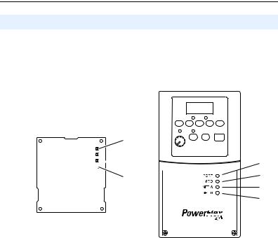
Components
Figure 1.1 Components of the Adapter
LEDs are located on bottom side of adapter board
|
|
|
|
|
|
|
|
|
|
|
|
|
|
|
|
|
|
|
|
|
|
|
|
|
|
|
|
|
|
|
|
|||||||
|
|
|
|
|||||||||
Item |
Component |
Description |
|
|||||||||
|
Status Indicators |
Four LEDs that indicate the status of the ControlNet connection, |
||||||||||
|
|
|
|
DSI, and the adapter. Refer to Chapter 8, Troubleshooting. |
||||||||
|
DSI Connector |
A 20-pin, single-row shrouded male header. An Internal Interface |
||||||||||
|
|
|
|
cable is connected to this connector and a connector on the drive. |
||||||||
|
Channel A Coax Receptacle |
Channel A BNC connection for the ControlNet cable. |
||||||||||
|
|
|
||||||||||
|
Channel B Coax Receptacle |
Channel B BNC connection for the ControlNet cable. |
||||||||||
|
|
|
||||||||||
|
1x/5x Operating Mode |
Selects Single (1x) or Multi-Drive (5x) mode of operation. Refer to |
||||||||||
|
Jumper (J7) |
Setting Operating Mode and Node Address Switches on page 2-1. |
||||||||||
|
ControlNet Node Address |
Sets a unique node address for the adapter. Refer to Setting |
||||||||||
|
Switches |
Operating Mode and Node Address Switches on page 2-1. |
||||||||||

1-2 Getting Started
Features
The ControlNet adapter features the following:
•The adapter is normally installed in a PowerFlex 40 or PowerFlex 400 drive. It can also be used in a DSI External Comms Kit (22-XCOMM-DC-BASE).
•A jumper lets you select between Single or Multi-Drive mode of operation. In Single mode (default), the adapter represents a single drive on one node. In Multi-Drive mode, the adapter represents up to 5 drives on one node.
•A number of configuration tools can be used to configure the adapter and connected drive. The tools include an external PowerFlex 4-Class HIM (22-HIM-*) or drive-configuration software such as DriveExplorer (version 3.01 or higher) or DriveExecutive (version 3.01 or higher).
•Status indicators report the status of drive communications, the adapter, and network.
•Supports I/O, including Logic Command/Reference, for all drives connected in Single or Multi-Drive mode.
•The following table shows the various controllers that can be used with the 22-COMM-C adapter and whether they support explicit messaging (parameter read/write, etc.) on a ControlNet network:
|
Supports Explicit Messaging |
|||
Controller Used With 22-COMM-C |
Single Mode |
Multi-Drive |
||
|
Yes |
No |
Yes |
No |
ControlLogix 1756-L55/L61/L62/L63 |
|
|
|
|
FlexLogix 1794-L33/L34 |
|
|
|
|
CompactLogix 1769-L20/L30/L35E |
|
|
|
|
MicroLogix1000 1761-L10/L16/L20/L32 |
|
|
|
|
MicroLogix1200 1762-L24/L40 |
|
|
|
|
MicroLogix1500 1764-LSP/LRP |
|
|
|
|
PLC-5 1785-L20C/L40C/L46C/L80C |
(1) |
|
|
|
SoftLogix 1789-L10/L30/L60 |
|
|
|
|
(1)Due to controller limitations, explicit messaging can only be performed on drive parameters up to Parameter 256.
•User-defined fault actions determine how the adapter and drive (or DSI External Comms Kit) respond to communication disruptions on the network and controllers in program mode.

Getting Started |
1-3 |
|
|
Compatible Products
The adapter is compatible with Allen-Bradley PowerFlex 4-Class (Component-Class) drives and other products that support an internal DSI adapter. At the time of publication, compatible products include:
•PowerFlex 4 drives with DSI External Comms Kit
•PowerFlex 40 drives
•PowerFlex 400 drives
Required Equipment
Equipment Shipped with the Adapter
When you unpack the adapter, verify that the package includes:
One ControlNet adapter
One 15.24 cm (6 in.) Internal Interface Cable
This manual
User-Supplied Equipment
To install and configure the adapter, you must supply:
A small flathead screwdriver
Appropriate ControlNet cables (refer to the ControlNet Fiber Media Planning and Installation Guide, Publication CNET-IN001…, for details.)
A configuration tool, such as:
–PowerFlex 4-Class HIM (22-HIM-*)
–DriveExplorer (version 3.01 or higher)
–DriveExecutive stand-alone software (version 3.01 or higher) or bundled with the DriveTools SP suite (version 1.01 or higher)
–RSNetWorx for ControlNet
Controller configuration software (Example: RSLogix 5000)
A PC connection to the ControlNet network
1-4 Getting Started
Safety Precautions
Please read the following safety precautions carefully.
!
!
!
!
!
!
!
ATTENTION: Risk of injury or death exists. The PowerFlex drive may contain high voltages that can cause injury or death. Remove  power from the PowerFlex drive, and then verify power has been discharged before installing or removing the adapter.
ATTENTION: Risk of injury or equipment damage exists. Only personnel familiar with drive and power products and the associated  machinery should plan or implement the installation, start-up, configuration, and subsequent maintenance of the product using the adapter. Failure to comply may result in injury and/or equipment damage.
ATTENTION: Risk of equipment damage exists. The adapter contains ESD (Electrostatic Discharge) sensitive parts that can be  damaged if you do not follow ESD control procedures. Static control precautions are required when handling the adapter. If you are unfamiliar with static control procedures, refer to Guarding Against Electrostatic Damage, Publication 8000-4.5.2.
ATTENTION: Risk of injury or equipment damage exists. If the adapter is transmitting control I/O to the drive, the drive may fault when  you reset the adapter. Determine how your drive will respond before resetting the adapter.
ATTENTION: Risk of injury or equipment damage exists. Parameters 08 - [Comm Flt Action] and 09 - [Idle Flt Action] let you determine the  action of the adapter and connected PowerFlex drive if communications
are disrupted. By default, these parameters fault the drive. You can set these parameters so that the drive continues to run. Precautions should be taken to ensure that the settings of these parameters do not create a risk of injury or equipment damage. When commissioning the drive, verify that your system responds correctly to various situations (for example, a disconnected cable or a faulted controller).
ATTENTION: Risk of injury or equipment damage exists. When a system is configured for the first time, there may be unintended or  incorrect machine motion. Disconnect the motor from the machine or process during initial system testing.
ATTENTION: Risk of injury or equipment damage exists. The examples in this publication are intended solely for purposes of  example. There are many variables and requirements with any application. Rockwell Automation, Inc. does not assume responsibility or liability (to include intellectual property liability) for actual use of the examples shown in this publication.

Getting Started |
1-5 |
|
|
Quick Start
This section is provided to help experienced users quickly start using the adapter. If you are unsure how to complete a step, refer to the referenced chapter.
Step |
|
Refer to … |
1 |
Review the safety precautions for the adapter. |
Throughout this |
|
|
manual |
2 |
Verify that the PowerFlex drive is properly installed. |
Drive User Manual |
3 |
Install the adapter. |
Chapter 2, |
|
Verify that the PowerFlex drive is not powered. Then, |
Installing the |
|
Adapter |
|
|
connect the adapter to the network using a ControlNet cable |
|
|
and to the drive using the Internal Interface cable. Use the |
|
|
captive screw to secure and ground the adapter to the drive. |
|
|
When installing the adapter in a DSI External Comms Kit, |
|
|
refer to the 22-XCOMM-DC-BASE Installation Instructions |
|
|
(Publication No. 22COMM-IN001…) supplied with the kit. |
|
4 |
Apply power to the adapter. |
Chapter 2, |
|
The adapter receives power from the drive. Apply power to |
Installing the |
|
Adapter |
|
|
the drive. The status indicators should be green. If they flash |
|
|
red, there is a problem. Refer to Chapter 8, Troubleshooting. |
|
5 |
Configure the adapter for your application. |
Chapter 3, |
|
Set the following parameters for the adapter as required by |
Configuring the |
|
Adapter |
|
|
your application: |
|
|
|
|
|
• I/O configuration |
|
|
• Fault actions |
|
6 |
Apply power to the ControlNet scanner and other |
— |
|
devices on the network. |
|
|
Verify that the scanner and network are installed and |
|
|
functioning in accordance with ControlNet standards, and |
|
|
then apply power to them. |
|
7 |
Configure the scanner or bridge to communicate with |
Chapter 4, |
|
the adapter. |
Configuring the I/O |
|
Use a network tool such as RSNetWorx for ControlNet to |
|
|
configure the scanner or bridge on the network. |
|
8 |
Create a ladder logic program. |
Chapter 5, |
|
Use a programming tool such as RSLogix to create a ladder |
Using the I/O |
|
logic program that enables you to: |
Chapter 6, |
|
• Control the adapter and connected drive using I/O. |
|
|
Using Explicit |
|
|
• Monitor or configure the drive using Explicit Messages. |
Messaging |
1-6 Getting Started
Modes of Operation
The adapter uses four status indicators to report its operating status. They can be viewed on the adapter or through the drive cover (Figure 1.2).
Figure 1.2 Status Indicators (location on drive may vary)


Bottom side of adapter board
Item |
Status |
Normal |
Description |
Indicator |
Status (1) |
||
|
PORT |
Green |
Normal Operation. The adapter is properly connected and |
|
|
|
is communicating with the drive. |
|
MOD |
Green |
Normal Operation. The adapter is operational and is |
|
|
|
transferring I/O data. |
|
|
Flashing |
Normal Operation. The adapter is operational but is not |
|
|
Green |
transferring I/O data. |
|
NET A or |
Green |
Normal Operation. The adapter channel is properly |
|
NET B |
|
connected and communicating on the network. |
|
Flashing |
Normal Operation. The adapter channel has a temporary |
|
|
|
||
|
|
Green |
error, or is in listen-only mode. |
|
|
Off |
Normal Operation. The adapter channel is disabled or not |
|
|
|
supported. |
(1)If all status indicators are off, the adapter is not receiving power. Refer to Chapter 2, Installing the Adapter, for instructions on installing the adapter.
If any other conditions occur, refer to Chapter 8, Troubleshooting.

Chapter 2
Installing the Adapter
Chapter 2 provides instructions for installing the adapter in a PowerFlex 40 or PowerFlex 400 drive. This adapter can also be installed in a DSI External Comms Kit. In this case, refer to the 22-XCOMM-DC-BASE Installation Instructions (Publication No. 22COMM-IN001…) supplied with the kit.
Topic |
Page |
Preparing for an Installation |
2-1 |
Setting Operating Mode and Node Address Switches |
2-1 |
Connecting the Adapter to the Network |
2-3 |
Connecting the Adapter to the Drive |
2-4 |
Applying Power |
2-7 |
Preparing for an Installation
Before installing the adapter, verify that you have all required equipment. Refer to Chapter 1, Getting Started.
Setting Operating Mode and Node Address Switches
Before installing the adapter, you must set its Operating Mode Jumper for Single or Multi-Drive operation, and its Node Address Switches to a unique ControlNet node address.
Important: New settings are recognized only when power is applied to the adapter, or the adapter is reset. If you change a setting, cycle power or reset the adapter to invoke the change.
|
|
ATTENTION: Risk of equipment damage exists. The adapter |
|
! |
contains ESD (Electrostatic Discharge) sensitive parts that can be |
|
damaged if you do not follow ESD control procedures. Static control |
|
|
|
precautions are required when handling the adapter. If you are |
|
|
unfamiliar with static control procedures, refer to Guarding Against |
|
|
Electrostatic Damage, Publication 8000-4.5.2. |
|
|
|

2-2 Installing the Adapter
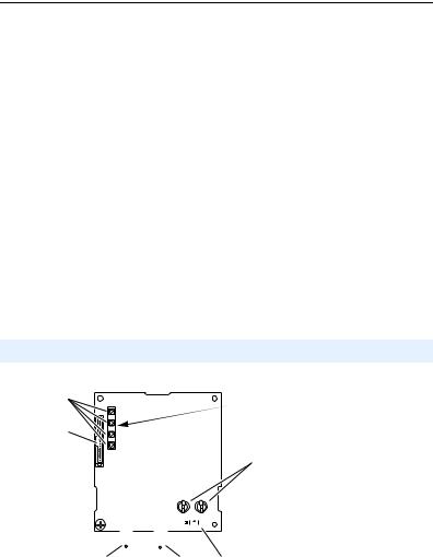
1.Set the adapter Operating Mode Jumper (J7) for Single (1x) or Multi-Drive (5x) operation (see Figure 2.1 and setting descriptions below). For complete details on Multi-Drive mode operation, see Chapter 7, Using Multi-Drive Mode.
Figure 2.1 Setting Single/Multi-Drive Operation and Node Address Switches
S2 |
S3 |
|
|
(Tens Digit) |
(Ones Digit) |
||
2 |
3 |
2 |
3 |
Node Address
Switches
1 |
|
4 |
1 |
4 |
0 |
|
5 |
0 |
5 |
9 |
|
6 |
9 |
6 |
8 |
7 |
|
8 |
7 |
|
J7 |
|
Operating |
|
J7 |
Mode Jumper |
|
|
5x |
1x |
|
|
Multi-Drive |
Single Mode |
|
|
Mode |
|
|
Jumper Setting |
Description |
|
|
Right (1x) |
Sets the adapter for Single mode (default setting) using a single |
||
position or jumper |
drive connection. |
|
|
missing |
Important: In this mode, connections to multiple drives must be |
||
|
|||
|
removed since all powered and connected hosts will respond to |
||
|
any message sent by the adapter. |
|
|
Left (5x) position |
Sets the adapter for Multi-Drive mode using up to 5 different |
||
|
drives. DSI peripherals (22-HIM-*, 22-SCM-*, etc.) do not |
||
|
operate with the adapter in this mode. |
|
|
2.Set the adapter node address by rotating the Node Address Switches to the desired value for each digit.
Important: Each node on the network must have a unique address. The node address must be set before power is applied because the adapter uses the node address it detects when it first receives power. To change a node address, you must set the new value. Then remove and reapply power to the adapter, or reset the adapter.
Switch Settings |
Description |
00-99 |
Node address used by the adapter if switches are enabled. The |
|
default switch setting is 02. |
|
Important: If the address switches are set to “00,” the adapter |
|
will use the setting of Parameter 02 - [CN Addr Cfg] for the |
|
node address. Refer to Setting the Node Address on page 3-3. |
The node address switch settings can be verified using a PowerFlex 4-Class HIM, DriveExplorer, or DriveExecutive to view Diagnostic Item number 28 (listed on page 8-5 or page 8-6).
Installing the Adapter |
2-3 |
|
|
|
|
Connecting the Adapter to the Network |
|
|
|
|
|
ATTENTION: Risk of injury or death exists. The PowerFlex drive |
|
! |
may contain high voltages that can cause injury or death. Remove |
|
power from the PowerFlex drive, and then verify power has been |
|
|
|
discharged before installing or removing an adapter. |
|
|
|
1.Remove power from the drive.
2.Use static control precautions.
3.Remove the drive cover.
4.Connect a ControlNet cable to the ControlNet network. See Figure 2.2 for an example of wiring to a ControlNet network.
Figure 2.2 Connecting the ControlNet Cable to the Network
ControlLogix Controller |
|
PowerFlex 40 or PowerFlex 400 Drives |
||||||||
|
with 1756-CNB/R |
|
(each with a 22-COMM-C ControlNet Adapter) |
|||||||
|
|
|
|
|
|
|
|
|
|
|
|
|
|
|
|
|
|
|
|
|
|
|
|
|
|
|
|
|
|
|
|
|
|
|
|
|
|
|
|
|
|
|
|
|
|
|
|
|
|
|
|
|
|
|
|
|
|
|
|
|
|
|
|
|
|
|
|
|
|
|
|
|
|
|
|
|
|
|
|
|
|
|
|
|
|
|
|
|
|
|
|
|
|
|
|
|
|
|
|
|
|
|
|
|
|
|
|
|
|
|
|
|
|
|
|
|
|
|
|
|
|
|
|
|
|
|
|
|
|
|
|
|
|
|
|
|
|
|
|
|
|
|
|
|
|
|
|
|
|
|
|
|
|
|
|
|
|
|
|
|
|
|
|
|
ControlNet Network
(optional redundancy)
5.Route the ControlNet cable through the bottom of the PowerFlex drive (Figure 2.3), and insert the cable plug into the adapter’s mating receptacle.
2-4 Installing the Adapter
Connecting the Adapter to the Drive
PowerFlex 40 Frames B and C, and PowerFlex 400 Frame C
1.Remove power from the drive.
2.Use static control precautions.
3.Mount the adapter on the required special drive cover (ordered separately — see Figure 2.4 for part numbers).
•Frame C: Use the adapter screw to secure the adapter to the cover.
•Frame B: Disregard the screw and snap the adapter in place.
Important: For Frame C drives, tighten the adapter’s lower left screw to ground the adapter (see Figure 2.4). For Frame B drives, install the special drive cover onto the drive using both cover fasteners to ground the adapter.
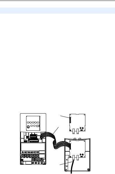
4.Connect the Internal Interface cable to the DSI port on the drive and then to the mating DSI connector on the adapter.
Figure 2.3 Connecting DSI Ports with Internal Interface Cable
22-COMM-C Adapter
PowerFlex 40 Drive (Frame C shown
with cover removed) Back of Required Special Drive Cover
Item |
Description |
|
DSI connector |
|
|
|
15.24 cm (6 in.) Internal Interface cable |
|
|
|
ControlNet cable |
|
|
Installing the Adapter |
2-5 |
|
|
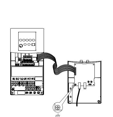
Figure 2.4 Mounting and Grounding the Adapter – PowerFlex 40 Frames B and C, and PowerFlex 400 Frame C
Adapter Mounted on Back of Required Special Drive Cover (Frame C cover shown)
PowerFlex 40 Frame B -- Part Number 22B-CCB
PowerFlex 40 Frame C -- Part Number 22B-CCC
PowerFlex 400 Frame C -- Part Number 22C-CCC
PowerFlex 40 Drive (Frame C shown with cover removed)
Ground for Frame C Drives
NOTE: For Frame B drives, the lower left adapter screw does not ground the adapter. To ground the adapter, install the special drive cover onto the drive using both cover fasteners.
2-6 Installing the Adapter
PowerFlex 400 Frames D, E, and F
1.Remove power from the drive.
2.Use static control precautions.
3.Remove the drive cover.
4.With the adapter board right side up, remove its mounting screw from the lower left hole. Save the screw for mounting in Step 7.
5.Connect the Internal Interface cable to the DSI port on the drive (see Figure 2.5).
6.With the adapter board oriented bottom side up, route the Internal Interface cable under the adapter, and then to the mating DSI connector on the adapter.
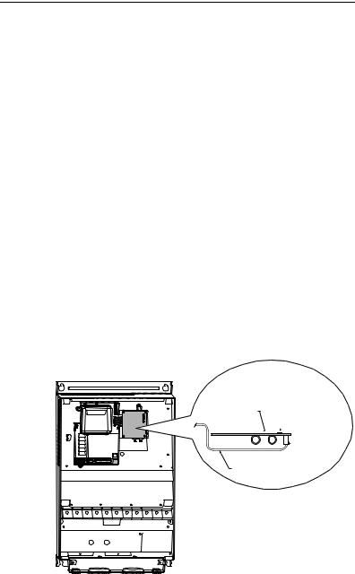
7.Install the adapter, bottom side up, to the right side of the display board by snapping it into place. Then insert the adapter mounting screw into the lower left hole on the board.
Important: Tighten the mounting screw in the adapter’s lower left hole to ground the adapter to the drive.
Figure 2.5 Mounting and Connecting the Adapter – PowerFlex 400 Frame D, E, and F Drives
Adapter Installation
(Side View)
Bottom of
Adapter Board
 LEDs
LEDs
 Connector
Internal Interface
Ribbon Cable
PowerFlex 400 (Frame D shown with cover removed)
Installing the Adapter |
2-7 |
|
|
Applying Power
|
|
ATTENTION: Risk of equipment damage, injury, or death exists. |
|
! |
Unpredictable operation may occur if you fail to verify that parameter |
|
settings and switch settings are compatible with your application. |
|
|
|
Verify that settings are compatible with your application before |
|
|
applying power to the drive. |
|
|
|
1.Install the drive cover. The status indicators can be viewed on the front of the drive after power has been applied.
2.Apply power to the PowerFlex drive. The adapter receives its power from the connected drive. When you apply power to the adapter for the first time, the status indicators should be green or off after an initialization. If the status indicators are red, there is a problem. Refer to Chapter 8, Troubleshooting.

2-8 Installing the Adapter
Notes:

Chapter 3
Configuring the Adapter
Chapter 3 provides instructions and information for setting the parameters in the adapter.
Topic |
Page |
Configuration Tools |
3-1 |
Using the PowerFlex 4-Class HIM |
3-2 |
Setting the Node Address |
3-3 |
Setting the I/O Configuration |
3-3 |
Setting a Fault Action |
3-4 |
Resetting the Adapter |
3-6 |
Viewing the Adapter Configuration |
3-7 |
For a list of parameters, refer to Appendix B, Adapter Parameters. For definitions of terms in this chapter, refer to the Glossary.
Configuration Tools
The adapter stores parameters and other information in its own non-volatile memory. You must, therefore, access the adapter to view and edit its parameters. The following tools can be used to access the adapter parameters:
Tool |
Refer to… |
PowerFlex 4-Class HIM |
page 3-2 |
(22-HIM-*) |
|
DriveExplorer Software |
http://www.ab.com/drives/driveexplorer, and |
(version 3.01 or higher) |
DriveExplorer online help (installed with the software) |
DriveExecutive Software |
http://www.ab.com/drives/drivetools, and |
(version 3.01 or higher) |
DriveExecutive online help (installed with the software) |

3-2 Configuring the Adapter
Using the PowerFlex 4-Class HIM
The PowerFlex 4-Class HIM (Human Interface Module) can be used to access parameters in the adapter (see basic steps shown below). It is recommended that you read through the steps for your HIM before performing the sequence. For additional HIM information, refer to the HIM Quick Reference card.
Note: The HIM will only work when the adapter is set to Single mode.
Using the HIM
Step |
Key(s) |
Example Screens |
|
|
|
|
|||||||
1. Power up the drive. |
|
|
|
|
|
|
|
|
|
|
|
|
|
Then plug the HIM |
|
|
|
|
|
|
Parameters |
|
|
|
|
||
|
|
|
|
|
|
|
|
|
|
|
|
|
|
into the drive. The |
|
|
|
|
|
|
Groups |
|
|
|
|
|
|
Parameters menu for |
|
|
|
|
|
|
Linear List |
|
|
|
|
||
the drive will be |
|
|
|
|
|
|
Changed Params |
|
|
|
|||
displayed. |
|
|
|
|
|
|
|
|
|
|
|
|
|
|
|
|
|
|
|
|
|
|
|
|
|
|
|
|
|
|
|
|
|
|
DIAG |
PARAM |
|
DSEL |
MEM |
SEL ! |
|
2. Press Sel key once to |
|
|
|
|
|
|
|
|
|
|
|
|
|
display the Device |
Sel |
|
Device Select |
|
|
|
|
||||||
|
|
|
|
|
|
|
|
||||||
Select menu. |
|
|
|
|
|
|
|
|
|
|
|
|
|
|
|
|
|
|
|
DSI Devices |
|
|
|
|
|||
|
|
|
|
|
|
|
|
|
|
|
|
|
|
|
|
|
|
|
|
|
DIAG |
PARAM |
|
DSEL |
MEM |
SEL ! |
|
3. Press Enter to display |
|
|
|
|
|
|
|
|
|
|
|
|
|
the DSI Devices |
|
|
|
|
and |
|
DSI Devices |
|
|
|
|
||
menu. Press Down |
|
|
|
|
|
|
PowerFlex 40 |
|
|
|
|
||
Arrow to scroll to |
|
|
|
|
|
|
|
|
|
|
|
|
|
|
|
|
|
|
|
22-COMM-C |
|
|
|
|
|||
22-COMM-C. |
|
|
|
|
|
|
|
|
|
|
|
|
|
4. Press Enter to select |
|
|
|
|
|
|
|
|
|
|
|
|
|
|
|
|
|
|
|
|
|
|
|
|
|
|
|
|
|
|
|
|
|
|
|
|
|
|
|
|
|
the adapter. The |
|
|
|
|
|
|
Parameters |
|
|
|
|
||
|
|
|
|
|
|
|
|
|
|
|
|
|
|
Parameters menu for |
|
|
|
|
|
|
|
|
|
|
|
||
|
|
|
|
|
|
Linear List |
|
|
|
|
|||
the adapter will be |
|
|
|
|
|
|
Changed Params |
|
|
|
|||
displayed. |
|
|
|
|
|
|
|
|
|
|
|
|
|
|
|
|
|
|
|
|
|
|
|
|
|
|
|
|
|
|
|
|
|
|
DIAG |
PARAM |
|
DSEL |
MEM |
SEL ! |
|
5. Press Enter to access |
|
|
|
|
|
|
|
|
|
|
|
|
|
the parameters. Edit |
|
|
|
|
|
|
Mode |
|
|
|
|
RO |
|
|
|
|
|
|
|
|
|
|
|
|
|
|
|
the adapter |
|
|
|
|
|
|
Parameter: |
|
# |
|
|
||
|
|
|
|
|
|
|
001 |
|
|||||
parameters using the |
|
|
|
|
|
|
|
|
|
|
|
|
|
same techniques that |
|
|
|
|
|
|
|
Single Drv |
|
0 |
|
||
you use to edit drive |
|
|
|
|
|
|
|
|
|
||||
|
|
|
|
|
|
|
|
|
|
|
|
|
|
parameters. |
|
|
|
|
|
|
|
|
|
|
|
|
|
|
|
|
|
|
|
|
VALUE |
LIMITS |
|
|
|
SEL ! |
|
|
|
|
|
|
|
|
|
|
|
|
|
|
|

Configuring the Adapter |
3-3 |
|
|
Setting the Node Address
If the Node Address Switches on the adapter are set to a node address of “00,” the value of Parameter 02 - [CN Addr Cfg] determines the ControlNet node address.
1.Set the value of Parameter 02 - [CN Addr Cfg] to a unique node address.
Figure 3.1 Node Address Screen on PowerFlex 4-Class HIM (22-HIM-*)
CN Addr Cfg |
|
|
Default = 2 |
|
Parameter: |
# |
|
|
|
002 |
|
|||
|
|
2 |
|
|
|
|
|
|
|
VALUE |
LIMITS |
|
SEL ! |
|
2. Reset the adapter (see Resetting the Adapter on Page 3-6).
Setting the I/O Configuration
The I/O configuration determines the number of drives that will be represented on the network as one node by the adapter. If the Operating Mode Jumper (J7 in Figure 2.1) is set to the “1x” (Single mode) default position, only one drive is represented by the adapter and Parameter 12 - [DSI I/O Cfg] has no effect. If the Operating Mode Jumper is set to the “5x” (Multi-Drive) position, up to five drives can be represented as one node by the adapter.
1.Set the value in Parameter 12 - [DSI I/O Cfg].
Figure 3.2 I/O Configuration Screen on Powerflex 4-Class HIM (22-HIM-*)
DSI I/O Cfg
Parameter: |
# |
012 |
||
|
|
Drive 0 |
0 |
|
|
|
|
|
|
VALUE |
LIMITS |
|
|
SEL ! |
Value |
Description |
Mode Jumper Position |
||
Single |
Multi-Drive |
|||
|
|
|||
0 |
Drive 0 (Default) |
|
|
|
1 |
Drives 0-1 |
|
|
|
2 |
Drives 0-2 |
|
|
|
3 |
Drives 0-3 |
|
|
|
4 |
Drives 0-4 |
|
|
|
When the adapter is internally mounted in a PowerFlex 40 or 400 drive, this drive is always Drive 0. Drives 1 through 4 are PowerFlex

3-4 Configuring the Adapter
4-Class drives that are daisy-chained to the RJ45 (RS-485) port on Drive 0. When the adapter is externally mounted in a DSI External Comms Kit, Drives 0 through 4 are daisy-chained to the RJ45 (RS-485) port on the Comms Kit. Refer to Chapter 7, Using Multi-Drive Mode for more information.
2.If a drive is enabled, configure the parameters in the drive to accept the Logic Command and Reference from the adapter. For example, set a PowerFlex 40 drive’s parameter P036 - [Start Source] and parameter P038 - [Speed Reference] both to “5” (Comm Port). When using the adapter in Multi-Drive mode, each daisy-chained drive requires that additional parameters be set. See Configuring the RS-485 Network on page 7-7 for these parameters and their settings.
3.Reset the adapter (see Resetting the Adapter on page 3-6).
Setting a Fault Action
By default, when communications are disrupted (for example, a cable is disconnected) or the controller is in program mode, the drive responds by faulting if it is using I/O from the network. You can configure a different response to communication disruptions using Parameter 08 - [Comm Flt Action] and a different response to a controller in program mode using Parameter 09 - [Idle Flt Action].
|
! |
ATTENTION: Risk of injury or equipment damage exists. |
|
Parameters 08 - [Comm Flt Action] and 09 - [Idle Flt Action] let you |
|
|
determine the action of the adapter and connected drive if |
|
|
|
communications are disrupted or the controller is in program mode. By |
|
|
default, these parameters fault the drive. You can set these parameters |
|
|
so that the drive continues to run. Some ControlNet scanners may |
|
|
operate differently when a controller is in program mode which could |
|
|
limit the Idle Fault Action’s operating states. Precautions should be |
|
|
taken to ensure that the settings of these parameters do not create a risk |
|
|
of injury or equipment damage. When commissioning the drive, verify |
|
|
that your system responds correctly to various situations (for example, a |
|
|
disconnected cable or faulted controller). |
|
|
|
Loading...