


 Loading...
Installation Instructions
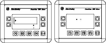
PanelView 300 Micro Terminals
(Catalog Numbers 2711-M3A18L1, 2711-M3A19L1)
Inside: |
|
English..................................................................................................... |
3 |
Français ................................................................................................. |
25 |
Deutsch ................................................................................................. |
47 |
Español.................................................................................................. |
69 |
Italiano .................................................................................................. |
91 |
41061-156-01(A)

2 PanelView 300 Micro Terminals
41061-156-01(A)

Installation Instructions
English
PanelView 300 Micro Terminal
(Catalog Numbers 2711-M3A18L1, 2711-M3A19L1)
Inside: |
|
For More Information.............................................................................. |
4 |
European Communities (EC) Directive Compliance ................................ |
4 |
Hazardous Locations ............................................................................... |
5 |
Wiring and Safety Guidelines................................................................. |
6 |
Mounting the Terminal............................................................................ |
6 |
Connecting DC Power ........................................................................... |
10 |
Using the Communications Port ........................................................... |
13 |
Accessing Configuration Mode ............................................................ |
18 |
Resetting the Terminal.......................................................................... |
18 |
Comm and Fault Indicators ................................................................... |
19 |
Troubleshooting and Maintenance ....................................................... |
20 |
Accessories ........................................................................................... |
22 |
Specifications ....................................................................................... |
23 |
41061-156-01(A)

4 PanelView 300 Micro Terminal
For More Information
For |
Refer to |
Refer to |
|
|
|
More detailed information on the 300 Micro and |
Standard PanelView |
2711-UM014A-EN-P |
the other Standard PanelView terminals. |
Terminals User Manual |
|
|
|
|
If you would like a publication, you can:
•download a free electronic version from the PanelBuilder32 installation CD
•download a free electronic version from the internet: www.ab.com/manuals/eoi or www.theautomationbookstore.com
To purchase a publication:
•visit the www.theautomationbookstore.com and place your order
•contact your local distributor or Rockwell Automation Representative
European Communities (EC) Directive
Compliance
This product has the CE mark and is approved for installation within the European Union and EEA regions. It has been designed and tested to meet the following directives.
EMC Directive
This product is tested to meet the Council Directive 89/336/EC Electromagnetic Compatibility (EMC) by applying the following standards:
•EN 50081-2 EMC - Generic Emission Standard, Part 2 - Industrial Environment
•EN 61000-6-2 EMC - Generic Standard, Immunity for Industrial Environments.
This product is intended for use in an industrial environment.
41061-156-01(A)
PanelView 300 Micro Terminal |
5 |
|
|
Hazardous Locations
This equipment is suitable for use in Class 1, Division 2, Groups A, B, C, D or non-hazardous locations only. The following DANGER statement applies to use in hazardous locations.
DANGER |
Explosion Hazard |
|
|
•Substitution of components may impair suitability for Class I, Division 2.
!• Do not disconnect equipment unless power has been switched off and area is known to be non-hazardous.
•Do not connect or disconnect components unless power has been switched off.
•All wiring must comply with N.E.C. article 501-4(b).
•Peripheral equipment must be suitable for the location it is used in.
Use only the following communication cables in Class 1, Division 2, Hazardous Locations.
Environmental Classification |
Communication Cable |
1761-CBL-PM01, Series C
1761-CBL-HM02, Series C
1761-CBL-AM00, Series C
1761-CBL-AP00, Series C
Class I, Division 2, Hazardous Locations
2711-CBL-PM05, Series C
2711-CBL-HM05, Series C
2711-CBL-PM10, Series C
2711-CBL-HM10, Series C
41061-156-01(A)
6 PanelView 300 Micro Terminal
Wiring and Safety Guidelines
Install the PanelView 300 Micro terminal using publication 70E, Electrical Safety Requirements for Employee Workplaces. In addition to the NFPA general guidelines, follow these recommendations:
•Route incoming power to the PanelView 300 Micro by a separate path from the communication cable.
•Where power and communication lines must cross, they should cross at right angles. Communication lines can be installed in the same conduit as low level DC I/O lines (less than 10 Volts).
•Grounding minimizes noise from Electromagnetic Interference (EMI) and is a safety measure in electrical installations. To avoid EMI, shield and ground cables appropriately.
A source for grounding recommendations is the National Electrical Code published by the National Fire Protection Association of Boston.
Mounting the Terminal
Enclosures
Mount the PanelView 300 Micro terminal in a panel or enclosure to protect the internal circuitry. The terminal meets NEMA 12/13 and 4X (indoor use) ratings only when properly mounted in a panel or enclosure with the equivalent rating.
Allow enough space within the enclosure for adequate ventilation. Consider heat produced by other devices in the enclosure. The ambient temperature around the PanelView 300 Micro must be between 0° and 55° C (32° and 131° F).
Make provisions for accessing the side panel of the terminal for wiring, maintenance and troubleshooting.
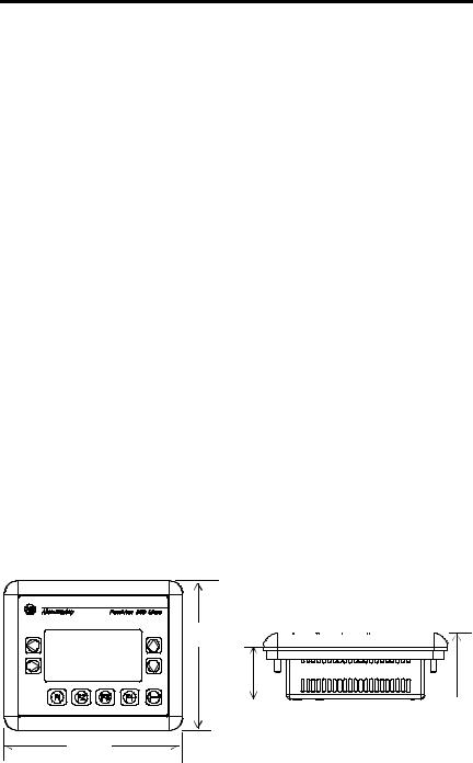
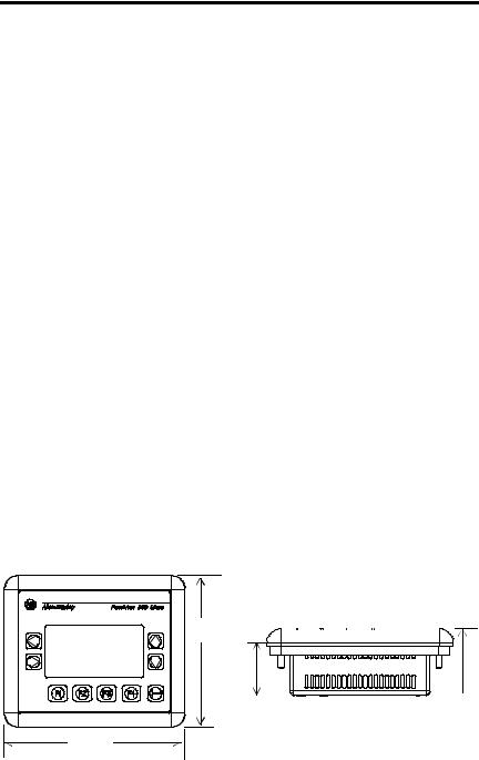
Mounting Dimensions
111 mm
(4.38 in.)
|
|
|
|
|
35 mm |
48 mm |
|||
(1.39 in.) |
(1.87 in.) |
|||
133 mm
(5.23 in.)
41061-156-01(A)

PanelView 300 Micro Terminal |
7 |
|
|
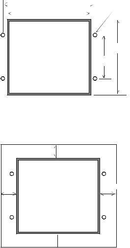
Cutout Dimensions
Use the full size template shipped with the PV300 Micro to mark the cutout dimensions. The figure below shows a reduced scale cutout. A full scale template is also available inside the back cover of this document.
|
|
|
|
|
|
|
|
|
|
|
|
|||
|
|
|
|
4.42 in. (112 mm) |
|
|
|
|
|
|
0.178 in. (4.5 mm) |
|||
|
|
|
|
|
|
|
||||||||
|
|
|
|
|
|
|
|
|
|
|
|
|||
|
|
|
|
|
|
|
|
|
|
|
|
|
Diameter |
|
|
|
|
4.0 in. (102 mm) |
|
|
|
|
|
|
|
|
|||
|
|
|
|
|
|
|
|
|
|
|
|
|||
|
|
|
|
|
|
|
|
|
|
|
|
|
|
|
|
|
|
|
|
|
|
|
|
|
|
|
|
|
|
|
|
|
|
|
|
|
|
|
|
|
|
|
|
|
3.62 in.
(92 mm)
2.12 in.
(54 mm)
Clearances
Allow 51 mm (2.0 inches) of space on all sides of the terminal for adequate ventilation and maintenance.
2.0 in. (51 mm) |
2.0 in. (51 mm) |
41061-156-01(A)
8 PanelView 300 Micro Terminal
Installing Terminal in Panel
Other than the tools required to make the panel cutout, the tools required for installation are:
•7 mm (M4) deep well socket wrench or nut driver
•small slotted screwdriver
•torque wrench (in. / lbs.)
To install the PV300 Micro in a panel:
ATTENTION |
• Disconnect all electrical power from the panel before |
|
making cutout. |
||
|
•Make sure area around the panel cutout is clear.
!• Take precautions so that metal cuttings do not enter any components already installed in panel.
•Failure to follow this warning may result in personal injury or damage to the panel components.
1.Cut an opening in the panel using the panel cutout provided with the terminal. Remove sharp edges or burrs.
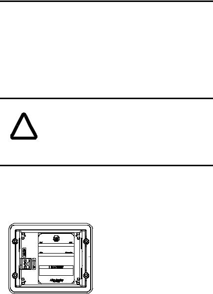
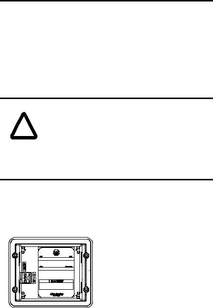
2.Make sure the sealing gasket is properly positioned on the terminal (as shown below). This gasket forms a compression type seal. Do not use sealing compounds.
 Sealing Gasket
3. Place the terminal in the panel cutout.
41061-156-01(A)
PanelView 300 Micro Terminal |
9 |
|
|
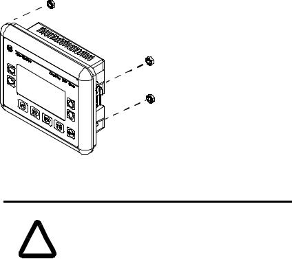
4. Install the 4 self-locking nuts, hand tight.
Self-Locking Nuts (4 used, 6 provided)
5.Alternately tighten the self-locking nuts until the terminal is held firmly against the panel. Tighten the nuts to a torque of 10 inch-pounds. Do not overtighten.
|
ATTENTION |
Mounting nuts must be tightened to a torque of 10 |
|
inch-pounds to provide a proper seal and to prevent |
|
|
|
|
|
! |
potential damage to the terminal. Allen-Bradley assumes no |
|
responsibility for water or chemical damage to the terminal |
|
|
or other equipment within the enclosure because of |
|
|
|
improper installation. |
|
|
|
41061-156-01(A)
10 PanelView 300 Micro Terminal
Connecting DC Power
The PV300 Micro terminal connects to a 24V dc power source. The table below shows the electrical ratings for the DC versions of the terminals. Electronic circuitry and an internal fuse protect the terminals from reverse polarity and over-voltage conditions.
Terminal Type |
Supply Voltage |
Power Consumption |
|
|
|
PV300 Micro |
11 to 30V dc |
2.5 Watts maximum |
|
(24V dc nominal) |
(0.105 Amps @24V dc) |
|
|
|
PV300 Micro terminal is designed for safe use when installed in a suitably rated NEMA Type 12, 13, 4X (indoor use only), IP54 or IP65 enclosure.
ATTENTION |
• Do not connect the PanelView terminal to an AC power |
|
source. Connecting to an AC power source will damage the |
||
|
||
|
terminal. |
!• Use only a Safety Extra Low-Voltage (SELV) power supply with an output rated between 11 - 30V dc as a power source for the PanelView 300 Micro. A SELV power supply does not exceed 42.4V dc.
The input power terminal block on the PanelView 300 Micro is removable and supports the following wiring types.
Wire Type |
Wire Size (2-wire maximum per terminal) |
|
|
Solid |
#16 to #22 AWG |
|
|
Stranded |
#18 to #22 AWG |
|
|
41061-156-01(A)
PanelView 300 Micro Terminal |
11 |
|
|
To connect DC power to the PanelView 300 Micro terminal:
1.Secure the DC power wires to the screw terminal block.
2.Secure the Functional Earth Ground wire to the screw terminal block.
DANGER |
Explosion Hazard |
|
|
•Substitution of components may impair suitability for Class I, Division 2.
!• Do not disconnect equipment unless power has been switched off and area is known to be non-hazardous.
•Do not connect or disconnect components unless power has been switched off.
•All wiring must comply with N.E.C. article 501-4(b).
3.Apply power (24V dc nominal) to the terminal.
+DC Positive
-DC Negative
 Functional Earth Ground
Removing and Installing the Power Terminal Block
You can remove and re-install the power terminal block for ease of installation, wiring and maintenance. The terminal block is pre-installed when shipped. Additional terminal blocks (quantity of 10) are available by ordering Catalog Number 2711-TBDC.
To remove the DC power terminal block:
1.Disconnect all electrical power from the panel. See Explosion Hazard Warning above.
2.Insert tip of small flat-blade screw driver into DC power terminal access slot.
41061-156-01(A)

12 PanelView 300 Micro Terminal
 Insert tip of screw driver here.
3.Gently push the blade of the screw driver away from the terminal block to release locking mechanism.
4.Remove DC power terminal block.
To re-install the DC power terminal block
Note: Install the terminal block with or without the power wires connected.
1.Disconnect all electrical power from the panel prior to installation. See Explosion Hazard Warning on previous page.
2.Position the terminal block at a 45° angle to the base surface and place lower edge of the wire connection side into the base.
3.Gently push the top of the terminal block back to a vertical position to snap in the locking tab.
Press terminal block  base in first with block leaning outward
Push top back to  vertical position
to lock-in.
41061-156-01(A)
PanelView 300 Micro Terminal |
13 |
|
|
Using the Communications Port
The PanelView 300 Micro terminal is available in 2 versions.
Catalog Number |
Communication Port |
Communication Protocol |
|
|
|
2711-M3A18L1 |
RS-232 |
DF1 |
|
|
|
2711-M3A19L1 |
RS-232 |
DH485 |
|
|
|
Both versions have an identical RS-232 communications port with a MicroLogix 8-pin mini-DIN style connector. The only difference is the protocol firmware (DF1 or DH485) pre-loaded at the factory. Both versions of the protocol firmware are supplied with the PanelBuilder32 software. You can change the protocol by downloading the firmware to the terminal using the Windows PanelView MotherBoard Firmware Download Utility (WinMBFWDL) utility. This utility is included with the PanelBuilder32 software.

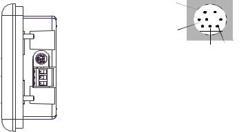
 RS-232
8-pin mini-DIN connector
 Port is used for both communications with a controller and to transfer application files.
2 |
|
|
|
|
1 |
|
|
|
|
||||
5 |
|
|
|
|
3 |
|
|
|
|
|
|||
4 |
|
|
8 |
7 |
6 |
Pin # Signal
1NC (No Connection)
2GND
3RTS
4RXD
5NC (No Connection)
6CTS
7TXD
8GND
The following table lists the communication parameters supported by each of the protocols on the RS-232 communications port.
Communication Link |
Communication Parameters |
|
|
RS-232 or DH-485 Link Point-to-Point |
|
Baud Rate: |
1200, 2400, 9600, 19.2K Baud |
Maximum Distance |
6.1 meters (20 feet) |
|
|
DF1 - Full Duplex Communication |
|
Baud Rate |
1200, 2400, 4800, 9600, 19.2K Baud |
Maximum Distance |
15.24 meters (50 feet) |
|
|
41061-156-01(A)

14 PanelView 300 Micro Terminal
Connecting to Controllers
This section lists the cables used by the PanelView 300 Micro to communicate with Allen-Bradley controllers and to operate on a DH-485 or DeviceNet network.
MicroLogix Controller |
Cable |
Cable Length |
|
|
|
|
|
Point-to-Point Communications with a |
1761-CBL-AM00, Series C |
0.5 meter (1.5 ft) |
|
MicroLogix 1000/1200/1500 controller |
|
|
|
1761-CBL-HM02, Series C |
2 meter (6.5 ft) |
||
using either DF1 or DH485 protocol over an |
|||
2711-CBL-HM05, Series C |
5 meter (15 ft) |
||
RS-232 link. |
|||
|
2711-CBL-HM10, Series C |
10 meter (30 ft) |
|
|
|
|
SLC/PLC-5/ControlLogix Controller |
Cables |
Cable Length |
|
|
|
|
|
Point-to-Point Communications with a SLC, |
1761-CBL-AP00, Series C |
0.5 meter (1.5 ft) |
|
PLC-5 or ControlLogix processor or module |
|
|
|
1761-CBL-PM02, Series C |
2 meter (6.5 ft) |
||
using either DF1 or DH485 protocol over an |
|
|
|
2711-CBL-PM05, Series C |
5 meter (15 ft) |
||
RS-232 link. |
|||
|
2711-CBL-PM10, Series C |
10 meter (30 ft) |
|
|
|
|
Advanced Interface Converter (AIC+) |
Cables |
Cable Length |
|
|
|
|
|
Point-to-point connection between the |
1761-CBL-AM00, Series C |
0.5 meter (1.5 ft) |
|
PanelView 300 Micro and an AIC+ module |
|
|
|
1761-CBL-APOO, Series C |
0.5 meter (1.5 ft) |
||
(Cat. No. 1761-NET-AIC). This connection |
|
|
|
1761-CBL-PM02, Series C |
2 meter (6.5 ft) |
||
allows the DH-485 version of the 300 |
|||
Micro to operate on a DH-485 network. |
1761-CBL-HM02, Series C |
2 meter (6.5 ft) |
|
|
|
|
|
|
2711-CBL-PM05, Series C |
5 meter (15 ft) |
|
|
|
|
|
|
2711-CBL-HM05, Series C |
5 meter (15 ft) |
|
|
|
|
|
|
2711-CBL-PM10, Series C |
10 meter (30 ft) |
|
|
|
|
|
|
2711-CBL-HM10, Series C |
10 meter (30 ft) |
|
|
|
|
DeviceNet Interface (DNI) |
Cables |
Cable Length |
|
|
|
|
|
Point-to-Point connection between a |
1761-CBL-AM00, Series C |
0.5 meter (1.5 ft) |
|
PanelView 300 Micro and the DNI module |
|
|
|
1761-CBL-HM02, Series C |
2 meter (6.5 ft) |
||
(Cat. No. 1761-NET-DNI). This connection |
|||
|
|
||
2711-CBL-HM05, Series C |
5 meter (15 ft) |
||
allows the DF1 version of the Micro 300 to |
|||
operate on a DeviceNet network. |
2711-CBL-HM10, Series C |
10 meter (30 ft) |
|
|
|
|
41061-156-01(A)

PanelView 300 Micro Terminal |
15 |
|
|
Bulletin 1761 or 2711-CBL-HMxx Cable Pinouts
These cables connect the PanelView 300 Micro terminal directly to a MicroLogix controller, AIC+ or DNI module for runtime communications.
|
|
|
|
|
|
|
|
|
|
|
|
|
|
|
|
|
|
|
|
|
|
|
|
|
|
|
|
|
|
|
|
|
|
|
|
|
|
|
|
|
|
|
|
|
|
|
|
|
|
|
|
|
|
|
|
|
|
|
|
|
|
|
|
|
|
|
|
|
|
|
|
|
|
|
|
|
|
|
|
|
|
|
|
|
|
|
|
|
|
|
|
|
|
|
|
|
|
|
|
|
|
|
|
|
|
|
|
|
|
|
|
|
|
|
|
|
|
|
|
|
|
|
|
|
|
|
|
|
8-Pin mini-DIN |
|
|
|
|
|
8-Pin mini-DIN |
|||||||||||
|
1 |
24V |
|
|
|
|
|
|
24V |
1 |
|
|
|
|||||||
|
|
|
|
|
|
|
|
|
|
|||||||||||
|
2 |
GND |
|
|
|
|
|
|
GND |
2 |
|
|
|
|||||||
|
|
|
|
|
|
|
|
|
|
|||||||||||
|
3 |
RTS |
|
|
|
|
|
|
RTS |
3 |
|
|
|
|||||||
|
|
|
|
|
|
|
|
|
|
|||||||||||
|
4 |
CTS |
|
|
|
|
|
|
|
CTS |
6 |
|
|
|
||||||
|
|
|
|
|
|
|
|
|
|
|
||||||||||
|
5 |
DCD |
|
|
|
|
|
|
|
DCD |
5 |
|
|
|
||||||
|
6 |
RXD |
|
|
|
|
|
|
RXD |
4 |
|
|
|
|||||||
|
|
|
|
|
|
|
|
|
|
|||||||||||
|
7 |
TXD |
|
|
|
|
|
|
|
TXD |
7 |
|
|
|
||||||
|
8 |
GND |
|
|
|
|
|
|
|
GND |
8 |
|
|
|
||||||
|
|
|
|
|
|
|
|
|
|
|
||||||||||
Bulletin 1761 or 2711-CBL-PMxx Cable Pinouts
These cables connect the PanelView 300 Micro terminal directly to a personal computer for application file transfers or to an SLC, PLC-5 or ControlLogix controller for runtime communications.
|
|
|
|
|
|
|
|
|
|
|
|
|
|
|
|
|
|
|
|
|
|
|
|
|
|
|
|
|
|
|
|
|
|
|
|
|
|
|
|
|
|
|
|
|
|
|
|
|
|
|
|
|
|
|
|
|
|
|
|
|
|
|
|
|
|
|
|
|
|
|
|
|
|
|
|
|
|
|
|
|
|
|
|
|
|
|
|
|
|
|
|
|
|
|
|
|
|
|
|
|
|
|
|
|
|
|
|
|
|
|
|
|
|
|
|
|
|
|
|
|
|
|
8-pin mini-DIN |
||||||||
|
|
|
|
|
|
|
|
|
|
|
|
|
|||||||||
9-Pin D-Shell |
|
|
|
|
|
||||||||||||||||
9 |
RI |
|
|
|
|
|
24V |
1 |
|
|
|
|
|||||||||
|
|
|
|
|
|
|
|
|
|||||||||||||
5 |
GND |
|
|
|
|
|
GND |
2 |
|
|
|
|
|||||||||
|
|
|
|
|
|
|
|
|
|||||||||||||
7 |
RTS |
|
|
|
|
|
RTS |
3 |
|
|
|
|
|||||||||
|
|
|
|
|
|
|
|
|
|||||||||||||
8 |
CTS |
|
|
|
|
|
|
CTS |
6 |
|
|
|
|
||||||||
|
|
|
|
|
|
|
|
|
|
||||||||||||
1 |
DCD |
|
|
|
|
|
|
DCD |
5 |
|
|
|
|
||||||||
|
|
|
|
|
|
|
|
|
|
||||||||||||
2 |
RXD |
|
|
|
|
|
RXD |
4 |
|
|
|
|
|||||||||
|
|
|
|
|
|
|
|
|
|||||||||||||
3 |
TXD |
|
|
|
|
|
|
TXD |
7 |
|
|
|
|
||||||||
|
|
|
|
|
|
|
|
|
|
||||||||||||
4 |
DTR |
|
|
|
|
|
|
GND |
8 |
|
|
|
|
||||||||
|
|
|
|
|
|
|
|
|
|
||||||||||||
6 |
DSR |
|
|
|
|
|
|
|
|
|
|
|
|
|
|
|
|||||
|
|
|
|
|
|
|
|
|
|
|
|
|
|
|
|||||||
41061-156-01(A)

16 PanelView 300 Micro Terminal
Transferring Application Files
Applications for the PanelView 300 Micro terminal are developed using PanelBuilder32 Software (Catalog Number 2711-ND3, V3.60 or later). You can transfer application files between a computer and the terminal over an RS-232 communication link using one of the following cables.
Download Cable |
Cable Length |
|
|
1761-CBL-PM02, Series C |
2 meter (6.5 ft) |
|
|
2711-CBL-PM05, Series C |
5 meter (15 ft) |
|
|
2711-CBL-PM10, Series C |
10 meter (30 ft) |
|
|
Three file transfer methods are available for the PanelView 300 Micro:
PanelBuilder32 Software
Supports the direct transfer of application files from PanelBuilder32 using an RS-232 link.
Windows PanelView File Transfer (WinPFT) Utility
Supports the direct transfer of PanelBuilder32 application files from WinPFT over an RS-232 link. The WinPFT utility is included with the PanelBuilder32 Software. RSLinx software may be required to transfer applications to the terminal for DH-485 and DF1 protocols.
This method is recommended for direct downloads to installed PanelView 300 Micro terminals using a portable or laptop computer.
Windows CE Pocket PanelView File Transfer (PocketPFT) Utility
Supports the direct transfer of PanelBuilder32 application files from the PocketPFT software over an RS-232 link. The PocketPFT software and an RS232 cable is available from Rockwell Software as part of the MaintenCE suite of tools. You will also need one of the recommended download cables.
This method is recommended for direct downloads to installed PanelView 300 Micro terminals using an HPC JORNADA portable CE computer, available only from Rockwell Software.
41061-156-01(A)
PanelView 300 Micro Terminal |
17 |
|
|
File Transfer Considerations
Because the communication port supports both runtime communications and application transfers,you must make sure the port is set properly.
For successful communications, the PV300 Micro and the communicating device must be set to the same communications settings and baud rate. The factory default setting is 9600 baud.
Downloaded Baud Rate Changes - After a successful application download, you may not be able to download another application. It is possible, the downloaded application was configured with a different run-time communication baud rate in the PanelBuilder32 software.
Run-Time Baud Rate Changes - After a successful application download, the PanelView 300 Micro may not be communicating with the logic controller. It is possible, the downloaded application was configured with a different communication baud rate than the connected logic controller.
To adjust the baud rate, you can either:
•enter Configuration Mode on the terminal and select the Communication Setup screen (looks similar to screen below). See page 18 to access Configuration Mode.
|
DF1 - Full Duplex |
|
|
F1 Comms |
N/8/1 |
|
F2 Baud |
9600 |
Press F2 to change |
F3 MORE |
F4 EXIT |
|
|
|
baud rate setting. |
|
|
 Current baud rate setting.
 Press F4 to save setting and exit.
•access the Communication Setup dialog from the Application Settings dialog in PanelBuilder32 and then redownload the application to the PV300 Micro.
41061-156-01(A)
18 PanelView 300 Micro Terminal
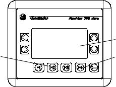
Accessing Configuration Mode
The PanelView 300 Micro terminal, like all standard PanelView terminals, has configuration screens you can access to review or modify terminal settings.
1.Apply power to the PanelView 300 Micro as described in previous sections.
2.Simultaneously press both the Left and Right arrow keys on the front panel.
You will not be able to access Configuration mode if the arrow keys are assigned to objects in the terminal application.
Press and release both the Left and Right arrow keys
simultaneously to enter Configuration Mode.
CONFIGURATION MODE
Language
 Communication
Preset Operations
F1 RUN MODE |
C |
F2 RESET VIDEO |
F |
Enter Key
3.The Configuration Mode menu displays the various options. Using the up and down arrow keys, navigate through the configuration screens to review terminal information, communication settings, time/date settings, display settings, and the current language setting.
Changes to settings take affect immediately (without powering off the terminal).
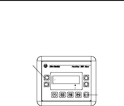
Resetting the Terminal
You can reset the PanelView 300 Micro from the front panel without having to remove and then re-apply power. A 3-key reset from the front panel is equivalent to a power cycle.
To reset, the PanelView 300 Micro:
Press and release both the Left and Right arrow keys and the Enter key simultaneously. The terminal resets.
41061-156-01(A)
PanelView 300 Micro Terminal |
19 |
|
|
Comm and Fault Indicators
The PanelView 300 Micro has a Comm (communication) and Fault (error) status indicator. These indicators are visible from Configuration Mode when selecting the Communication screen. Use the Comm and Fault indicators to isolate operating problems.
CONFIGURATION MODE |
DF1 - Full Duplex |
|||
Language |
|
Comm |
Fault |
|
Communication |
|
|||
Preset Operations |
C |
PanelView Online |
||
F1 RUN MODE |
F3 MORE |
F4 EXIT |
||
F2 RESET VIDEO |
F |
|||
|
|
|||
Indicator |
State |
Indicates |
|
|
|
Comm |
ON (steady state solid fill) |
Normal Operating (no communications fault) |
|
|
|
|
OFF (no fill) |
Fault detected. Verify: |
|
|
• controller is in run mode. |
|
|
• communication settings for terminal and |
|
|
controller. |
|
|
• terminal and controller node addresses. |
|
|
• terminal to controller connections. |
|
|
|
|
Blinking (flashing) |
No communications established. For DF1 terminals, |
|
|
the Comm indicator flashes until an application is |
|
|
loaded. |
|
|
|
Fault |
OFF (no fill pattern) |
Normal operating state |
|
|
|
|
ON (steady state solid fill) |
Fault detected. Reset or cycle power to the terminal. |
|
|
If the fault remains the terminal requires servicing. |
|
|
|
|
Blinking (flashing) |
Hardware is functioning but no application is loaded |
|
|
in the terminal or the current application is |
|
|
corrupted. Reload the application file into the |
|
|
terminal. |
|
|
|
41061-156-01(A)

20 PanelView 300 Micro Terminal
Troubleshooting and Maintenance
The troubleshooting chart below lists common operating problems, causes and corrective steps.
Problem |
Causes |
Corrective Action |
||
|
|
|
|
|
Terminal does not powerup |
1. |
Improper connection to |
1. |
Verify correct voltage at |
|
|
power source. |
|
power terminals. |
|
2. |
Incorrect input voltage level. |
2. Verify power source output |
|
|
3. |
Power terminal block |
|
is between 11 - 30V dc. |
|
3. |
Snap power terminal block |
||
|
|
removed. |
|
onto base on back of |
|
4. |
DC power wires reversed. |
|
terminal. |
|
4. |
Connect DC power positive |
||
|
|
|
|
and negative wires to |
|
|
|
|
correct terminals. |
|
|
|
|
|
Application File will not |
1. |
Communication cable |
1. |
Check communication cable |
download (first download) |
|
disconnected. |
|
type and connections. |
|
2. |
Incorrect baud rate or |
2. |
Verify computer and |
|
|
communication settings. |
|
terminal are set to same |
|
3. |
Incorrect computer COM |
|
communication settings. |
|
3. |
Verify correct COM port |
||
|
|
port selection. |
|
number in WinPFT or |
|
|
|
|
PanelBuilder32 software. |
|
|
|
|
|
Application File will not |
1. |
Incorrect communication or |
1. |
Verify computer and |
download (subsequent |
|
baud rate settings. |
|
terminal have same |
downloads) |
|
|
|
communication settings. |
|
|
|
|
Change settings in |
|
|
|
|
Communication setup |
|
|
|
|
screen of terminal. |
|
|
|
|
|
No communication with |
1. |
Communications Comm |
1. |
Check Comm indicator. See |
MicroLogix, ControlLogix, SLC |
|
fault. |
|
page 19. |
or PLC controller. |
2. |
Incorrect baud rates. |
2. |
Verify controller and |
|
3. |
Controller not in run mode. |
|
terminal set to same baud. |
|
3. |
Place controller in run mode. |
||
|
4. |
Incorrect terminal node and |
4. |
Verify node addresses. |
|
|
max node addresses. |
|
|
|
|
|
|
|
No communication with |
1. |
Incorrect node address of |
1. |
Verify node address of |
controller but Comm indicator |
|
controller. |
|
controller. |
is active. |
2. |
Inhibit bit set as default on |
2. |
Change inhibit bit setting. |
|
|
PLC channel status screen. |
|
|
|
|
|
|
|
Clock Module Battery Low |
1. |
Internal parameters corrupt. |
1. |
Reload application and cycle |
message displayed. |
|
|
|
power to terminal. |
|
2. |
Clock module battery failure. |
2. Replace terminal. |
|
|
|
|
|
|
Screen objects do not |
1. |
Communication problem. |
1. |
Check status of Comm |
function. |
|
|
|
indicator. |
|
|
|
|
|
41061-156-01(A)
|
|
PanelView 300 Micro Terminal |
21 |
|||
|
|
|
|
|
||
|
|
|
|
|
||
Problem |
Causes |
Corrective Action |
|
|
||
|
|
|
|
|
|
|
No communications with |
1. |
Communications Comm |
1. |
Check Comm indicator. See |
|
|
computer. |
|
fault. |
|
page 19. |
|
|
|
2. |
Incorrect baud rate or |
2. |
Verify computer and |
|
|
|
|
communication settings. |
|
terminal are at same baud. |
|
|
|
3. |
Incorrect terminal node or |
3. |
Verify node addresses. |
|
|
|
|
max node address. |
|
|
|
|
|
4. |
Computer fault. |
4. |
Refer to computer manual. |
|
|
|
5. |
Communications driver not |
5. |
Refer to RSLinx online help |
|
|
|
|
properly loaded. |
|
or manual. |
|
|
|
|
|
|
|
|
|
Application filename appears |
1. |
Application file invalid. |
1. |
Download application to |
|
|
as ****** on Terminal Info |
|
|
|
terminal. |
|
|
screen. |
2. |
Application unusable |
2. |
Download new application. |
|
|
|
|
because of error. |
|
|
|
|
|
|
|
|
|
|
|
Screen objects not visible. |
1. |
Correct power not applied. |
1. |
Verify power connections. |
|
|
|
2. |
Contrast not set correctly. |
2. |
Access Screen Setup from |
|
|
|
|
|
|
Configuration Mode and |
|
|
|
3. |
Terminal in screen saver |
|
adjust display contrast. |
|
|
|
3. |
Access Screen Setup from |
|
|
||
|
|
mode. |
|
Configuration Mode to |
|
|
|
|
|
|
check if terminal is in Screen |
||
|
|
|
|
Saver Mode. |
|
|
|
|
|
|
|
|
|
Values do not update on |
1. |
Terminal not communicating |
1. |
Check status of Comm |
|
|
display but appear as asterisks |
|
with logic controller. |
|
indicator. See problem “No |
|
|
**** |
|
|
|
communication with |
|
|
|
2. |
Value is invalid or exceeds |
|
controller” for details. |
|
|
|
2. |
Change the field width set |
|
|
||
|
|
the field width for object. |
|
for the object. |
|
|
|
|
|
|
|
|
|
LCD display is difficult to view. |
1. |
Display contrast level set |
1. |
Access Configuration mode |
|
|
|
|
incorrectly. |
|
and adjust the display |
|
|
|
|
|
|
contrast level. |
|
|
|
|
|
|
|
|
|
Can’t Configuration Mode |
1. |
Left and right arrow keys are |
1. |
Contact Technical Support |
|
|
when pressing Left and Right |
|
assigned to screen objects |
|
for assistance. |
|
|
arrow keys simultaneously. |
|
in the terminal application. |
|
|
|
|
|
|
|
|
|
|
|
No network found. |
1. |
Node setting of controller |
1. |
Change node address in |
|
|
|
|
does not match application. |
|
application to match |
|
|
|
2. |
Controller data file does not |
|
controller node address. |
|
|
|
2. |
Verify data file elements for |
|
|
||
|
|
have enough elements. |
|
all tag addresses. |
|
|
|
|
|
|
|
|
|
41061-156-01(A)

22 PanelView 300 Micro Terminal
Maintenance
The PanelView 300 Micro has no internal components that are user accessible. The rear cover is not removable, therefore, you should not remove it for troubleshooting or maintenance. The real-time clock battery and the LCD display backlight are not replaceable.
To clean the display window of the PanelView 300 Micro:
1.Disconnect power from the terminal at the power source.
2.Use a clean sponge or soft cloth to clean with a mild soap or detergent to clean the display. Do not scrub, use brushes, abrasive cleaners or solvents.
3.Dry the display with a chamois or moist cellulose sponge to avoid water spots.
Accessories
The following accessories are available for the PanelView 300 Micro.
PanelBuilder32 Software
Catalog No. |
Description |
Version |
|
|
|
2711-ND3 |
PanelBuilder32 Software for developing applications |
3.60 or later |
|
for the line of Standard PanelView terminals. |
|
|
|
|
DC Power Input Terminal Block
Catalog No. |
Description |
Quantity |
|
|
|
2711-TBDC |
Removable (3-position screw) DC Power Input Terminal Block |
10 |
|
|
|
Communication Cables
Cable |
Connector Type |
Cable Length |
|
|
|
1761-CBL-AM00, Series C |
8-pin mini-DIN to 8-pin mini-DIN |
0.5 meter (1.5 ft) |
|
|
|
1761-CBL-AP00, Series C |
8-pin mini-DIN to 9-pin D-Shell |
0.5 meter (1.5 ft) |
|
|
|
1761-CBL-PM02, Series C |
8-pin mini-DIN to 9-pin D-Shell |
2 meter (6.5 ft) |
|
|
|
1761-CBL-HM02, Series C |
8-pin mini-DIN to 8-pin mini-DIN |
2 meter (6.5 ft) |
|
|
|
2711-CBL-PM05, Series C |
8-pin mini-DIN to 9-pin D-Shell |
5 meter (15 ft) |
|
|
|
2711-CBL-HM05, Series C |
8-pin mini-DIN to 8-pin mini-DIN |
5 meter (15 ft) |
|
|
|
2711-CBL-PM10, Series C |
8-pin mini-DIN to 9-pin D-Shell |
10 meter (30 ft) |
|
|
|
2711-CBL-HM10, Series C |
8-pin mini-DIN to 8-pin mini-DIN |
10 meter (30 ft) |
|
|
|
41061-156-01(A)

PanelView 300 Micro Terminal |
23 |
|
|
Specifications
Electrical |
|
|
|
|
|
|
|
|
|
|
|
|
Supply Voltage Limits |
11 to 30V dc (24V dc nominal) |
|
||||||||||
Power Consumption |
2.5W maximum (0.105A @24V dc) |
|
||||||||||
Mechanical |
|
|
|
|
|
|
|
|
|
|
|
|
Enclosure |
NEMA Type 12/13, 4X (indoor use only), IP54, IP65 |
|||||||||||
Weight |
284 grams (10 oz.) |
|
|
|
|
|||||||
Dimensions |
133 (H) x 111 (W) x 48 (D) mm |
|
||||||||||
|
5.23 (H) x 4.38 (W) x 1.87 (D) inches |
|
||||||||||
Installed Depth |
35 mm (1.39 inches) |
|
|
|
||||||||
Display |
|
|
|
|
|
|
|
|
|
|
|
|
Type |
Liquid Crystal Display (LCD) with LED backlighting |
|||||||||||
Size |
73 mm (w) x 42 mm (h) |
|
|
|
||||||||
|
2.87 in. (w) x 1.67 in. (h) |
|
|
|
||||||||
Pixels |
128 x 64 |
|
|
|
|
|
|
|
|
|||
Environment |
|
|
|
|
|
|
|
|
|
|
|
|
Operating Temperature |
° |
to 55 |
° |
C (32 |
° |
|
° |
F) |
|
|||
|
0 |
|
|
to 131 |
|
|||||||
Storage Temperature |
° |
to 85 |
° |
C (-4 |
° |
to 188 |
° |
F) |
|
|||
|
-20 |
|
|
|
|
|
||||||
Humidity (non-condensing) |
|
|
|
|
|
° |
|
|
° |
|
° |
° |
|
5 to 95% at 0 |
to 55 C (32 to 131 |
F) |
|||||||||
Heat Dissipation |
2.5W (8.5 BTU/Hour) |
|
|
|
||||||||
Impulse Shock |
30G operating, 50G non-operating |
|
||||||||||
Vibration |
2G up to 2,000 Hz operating |
|
||||||||||
Agency Certifications |
|
|
|
|
|
|
|
|
|
|
|
|
When product is marked: |
UL |
|
|
|
|
|
|
|
|
|
|
|
|
CE marked for all applicable directives |
|||||||||||
|
c-UL Class I Div 2 Hazardous(1) |
|
||||||||||
(1) CSA certification - Class I, Division 2, Group A,B,C,D or nonhazardous locations
41061-156-01(A)

24 PanelView 300 Micro Terminal
41061-156-01(A)

Notice d’installation
Français
Terminal PanelView 300 Micro
(Références 2711-M3A18L1, 2711-M3A19L1)
Sommaire : |
|
Pour plus d’informations ....................................................................... |
26 |
Conformité aux directives de l’Union européenne ............................... |
26 |
Emplacements dangereux..................................................................... |
27 |
Câblage et consignes de sécurité......................................................... |
28 |
Dimensions de montage ....................................................................... |
28 |
Branchement de l’alimentation c.c. ...................................................... |
32 |
Utilisation du port de communication .................................................. |
35 |
Accès au mode de configuration .......................................................... |
40 |
Réinitialisation du terminal .................................................................. |
40 |
Indicateurs de communication et de défauts ....................................... |
41 |
Dépannage et maintenance.................................................................. |
42 |
Maintenance ......................................................................................... |
45 |
Caractéristiques .................................................................................... |
46 |
41061-156-01(A)

26 Terminal PanelView 300 Micro
Pour plus d’informations
Pour |
Se reporter au |
N° de publication |
|
document |
|
|
|
|
Une description plus détaillée sur le 300 Micro |
Manuel d’utilisation des |
2711-UM014A-FR-P |
et autres terminaux PanelView standard. |
terminaux PanelView |
|
|
|
|
Pour obtenir l’une de ces publications, vous pouvez :
•charger une version électronique gratuite à partir du CD d’installation PanelBuilder32
•charger une version électronique gratuite à partir d’internet à l’adresse suivante : www.ab.com/manuals/eoi or www.theautomationbookstore.com
Pour acheter une publication :
•visitez le site www.theautomationbookstore.com et passez votre commande
•contactez votre distributeur local ou votre représentant de Rockwell Automation
Conformité aux directives de l’Union européenne
Si ce produit porte le marquage CE, son installation dans les pays de l’Union européenne et de l’Espace Economique Européen a été approuvée. Il a été conçu et testé en conformité avec les directives suivantes.
Directive CEM
Cet appareil a été testé en termes de compatibilité électromagnétique (CEM) selon la directive 89/336/EEC à l'aide d'un cahier des charges et d'après les normes suivantes, en totalité ou partie :
•EN 50081-2 Compatibilité électromagnétique – Norme générique émission – Partie 2 : Environnement industriel
•EN 50082-2 Compatibilité électromagnétique – Norme générique immunité – Partie 2 : Environnement industriel.
Ce produit décrit dans le présent document est conçu pour une utilisation en environnement industriel.
41061-156-01(A)

Terminal PanelView 300 Micro |
27 |
|
|
Emplacements dangereux
Cet équipement ne convient qu’à une utilisation dans un environnement de Classe 1, Division 2, Groupes A, B, C, D ou non dangereux. L’avertissement ATTENTION suivant concerne l’utilisation en environnements dangereux.
DANGER |
Risque d’explosion |
|
|
•La substitution de composants peut rendre cet équipement impropre à une utilisation en environnement de Classe I,
!Division 2.
•Ne pas débrancher l’équipement tant que l’alimentation électrique n’a pas été coupée et que la zone n’est pas sans danger.
•Ne pas brancher ou débrancher de composants tant que l’alimentation électrique n’a pas été coupée.
•Les câblages doivent tous être conformes à la norme N.E.C. article 501-4(b).
•Les équipements périphériques doivent être appropriés à l’endroit dans lequel ils seront utilisés.
Utiliser exclusivement les câbles de communication suivants dans les environnements dangereux de Classe 1, Division 2.
Classification relative aux |
Câbles de communication |
environnements |
|
|
|
|
1761-CBL-PM01, série C |
|
|
|
1761-CBL-HM02, série C |
|
|
|
1761-CBL-AM00, série C |
|
|
Emplacements dangereux de Classe 1, |
1761-CBL-AP00, série C |
Division 2 |
2711-CBL-PM05, série C |
|
|
|
2711-CBL-HM05, série C |
|
|
|
2711-CBL-PM10, série C |
|
|
|
2711-CBL-HM10, série C |
|
|
41061-156-01(A)
28 Terminal PanelView 300 Micro
Câblage et consignes de sécurité
Installer le terminal PanelView 300 Micro en suivant les instructions figurant dans la publication américaine 70E, Electrical Safety Requirements for Employee Workplaces. Outre les consignes de sécurité générales NFPA (Association nationale de protection contre l’incendie), il convient de suivre les recommandations suivantes :
•Acheminer l’alimentation d’arrivée du PanelView 300 Micro par le biais d’un chemin séparé du câble de communication.
•Lorsque les lignes de courant et de communication doivent se croiser, elles doivent se croiser à angle droit. Les lignes de communication peuvent être installées dans le même conduit que les lignes d’E/S c.c. de bas niveau (de moins de 10 volts).
•La mise à la terre permet de réduire les interférences électromagnétiques (EMI) et constitue une mesure de sécurité sur les installations électriques. Pour éviter les interférences électromagnétiques, il convient de blinder les câbles et de les relier à la terre de manière appropriée.
Pour plus d’informations relatives aux recommandations en matière de mise à la terre, se reporter au National Electrical Code publié par la National Fire Protection Association of Boston.
Montage du terminal
Armoires
Monter le terminal PanelView 300 Micro dans un panneau ou une armoire pour protéger les circuits internes. Le terminal est conforme aux normes NEMA 12/13 et 4X (s’appliquant à une utilisation sous-abri), à condition qu’il soit monté correctement dans un panneau ou une armoire conformément aux normes appropriées. Veiller à laisser un espace suffisant à l’intérieur de l’armoire pour permettre une ventilation adéquate. Prendre en compte la chaleur produite par les autres dispositifs installés dans l’armoire. La température ambiante autour du PanelView 300 Micro doit être comprise entre 0 ° et 55 ° C (32 ° et 131 ° F).
Prévoir les accès au panneau latéral du terminal pour le câblage, la maintenance et le dépannage.
Dimensions de montage
111 mm
(4,38 in.)
|
|
|
|
|
35 mm |
48 mm |
|||
(1,39 in.) |
(1,87 in.) |
|||
133 mm
(5,23 in.)
41061-156-01(A)
Terminal PanelView 300 Micro |
29 |
|
|
Dimensions de la découpe
Utiliser le gabarit grandeur nature fourni avec le PV300 Micro pour déterminer les dimensions de la découpe. La figure ci-dessous montre la découpe à échelle réduite. Un gabarit grandeur nature est également disponible dans l’avant-derrière de couverture de ce document.
|
|
|
|
|
|
|
|
|
|
|
|
|||
|
|
|
|
112 mm (4,42 in.) |
|
|
|
|
|
|
4,5 mm (0,178 in.) |
|||
|
|
|
|
|
|
|
||||||||
|
|
|
|
|
|
|
|
|
|
|
|
|||
|
|
|
|
|
|
|
|
|
|
|
|
|
Diamètre |
|
|
|
|
102 mm (4,0 in.) |
|
|
|
|
|
|
|
|
|||
|
|
|
|
|
|
|
|
|
|
|
|
|||
|
|
|
|
|
|
|
|
|
|
|
|
|
|
|
|
|
|
|
|
|
|
|
|
|
|
|
|
|
|
|
|
|
|
|
|
|
|
|
|
|
|
|
|
|
92 mm
(3,62 in.)
54 mm
(2,12 in.)
Espacements
Laisser 51 mm (2,0 in.) d’espace sur tous les cô tés du terminal afin d’assurer une ventilation adéquate et un accès pour la maintenance.
51 mm (2,0 in.) |
51 mm (2,0 in.) |
41061-156-01(A)
30 Terminal PanelView 300 Micro
Installation du terminal dans un panneau
Outre les outils requis pour découper le panneau, les outils suivants sont nécessaires pour l’installation :
•une clé à tube de grande profondeur de 7 mm (M4) ou une clé à pipe
•un petit tournevis pour écrous à fente
•une clé dynamométrique
Pour installer le terminal PV300 Micro dans un panneau :
ATTENTION |
• Déconnecter toute alimentation électrique du panneau avant |
|
de réaliser la découpe. |
||
|
•Vérifier que l’espace environnant la découpe du panneau
!est dégagé.
•Prendre des précautions afin d’éviter que des copeaux métalliques ne pénètrent dans les composants, quels qu’ils soient, déjà installés dans le panneau.
•Si ces recommandations ne sont pas respectées, il y a risque de blessures ou dommages.
1.Couper une ouverture dans le panneau à l’aide du gabarit fourni avec le terminal. Eliminer les arêtes vives.
2.Veiller à ce que le joint d’étanchéité soit correctement positionné sur le terminal (comme indiqué ci-dessous). Ce joint forme une étanchéité de type compression. Ne pas utiliser de produit d’étanchéité.
 Joint d'étanchéité
3. Placer le terminal dans la découpe du panneau.
41061-156-01(A)
Loading...