


 Loading...
User Manual
PanelView Component HMI Terminals
Catalog Numbers 2711C-F2M, 2711C-K2M, 2711C-T3M, 2711C-K3M, 2711C-T4T, 2711C-T6M, 2711C-T6C, 2711C-T6T, 2711C - T10C
Important User Information
Solid state equipment has operational characteristics differing from those of electromechanical equipment. Safety Guidelines for the Application, Installation and Maintenance of Solid State Controls (publication SGI-1.1 available from your local Rockwell Automation sales office or online at http://www.rockwellautomation.com/literature/) describes some important differences between solid state equipment and hard-wired electromechanical devices. Because of this difference, and also because of the wide variety of uses for solid state equipment, all persons responsible for applying this equipment must satisfy themselves that each intended application of this equipment is acceptable.
In no event will Rockwell Automation, Inc. be responsible or liable for indirect or consequential damages resulting from the use or application of this equipment.
The examples and diagrams in this manual are included solely for illustrative purposes. Because of the many variables and requirements associated with any particular installation, Rockwell Automation, Inc. cannot assume responsibility or liability for actual use based on the examples and diagrams.
No patent liability is assumed by Rockwell Automation, Inc. with respect to use of information, circuits, equipment, or software described in this manual.
Reproduction of the contents of this manual, in whole or in part, without written permission of Rockwell Automation, Inc., is prohibited.
Throughout this manual, when necessary, we use notes to make you aware of safety considerations.
WARNING: Identifies information about practices or circumstances that can cause an explosion in a hazardous environment, which may lead to personal injury or death, property damage, or economic loss.
ATTENTION: Identifies information about practices or circumstances that can lead to personal injury or death, property damage, or economic loss. Attentions help you identify a hazard, avoid a hazard, and recognize the consequence
WARNING: Labels may be on or inside the equipment, for example, a drive or motor, to alert people that dangerous voltage may be present.
WARNING: Labels may be on or inside the equipment, for example, a drive or motor, to alert people that surfaces may reach dangerous temperatures.
IMPORTANT Identifies information that is critical for successful application and understanding of the product.
Rockwell Automation, Allen-Bradley, PanelView, PanelView Component, Connected Components Workstation, and TechConnect are trademarks of Rockwell Automation, Inc.
Trademarks not belonging to Rockwell Automation are property of their respective companies.
|
2 |
Rockwell Automation Publication 2711C-UM001I-EN-P - July 2014 |

Summary of Changes
The information below summarizes the changes to this manual since the last publication.
To help you find new and updated information in this release of the manual, we included change bars as shown to the right of this paragraph.
Topic |
Section |
|
|
Only the 2711C-T4T catalog is UL Listed for |
56 |
Class I, Division 2 Group A,B,C,D Hazardous |
|
Locations, certified for U.S. and Canada. |
|
|
|
For 2711C-T4T only UL Listed for Class I, |
97 |
Division 2 Group A,B,C,D Hazardous |
|
Locations, certified for U.S. and Canada. |
|
See UL File E10314. |
|
|
|
EAC |
97 |
|
|
RCM |
97 |
|
|
Publication 2711C-UM001I-EN-P - July 2014 |
3 |
|

Summary of Changes
Notes:
4 |
Publication 2711C-UM001I-EN-P - July 2014 |

|
|
Table of Contents |
Summary of Changes |
|
|
Table of Contents |
|
|
Preface |
Objectives . . . . . . . . . . . . . . . . . . . . . . . . . . . . . . . . . . . . . |
. . . . . . . . . . . . . . . . . . . 9 |
|
Intended Audience . . . . . . . . . . . . . . . . . . . . . . . . . . . . . |
. . . . . . . . . . . . . . . . . . . 9 |
|
Additional Resources . . . . . . . . . . . . . . . . . . . . . . . . . . . |
. . . . . . . . . . . . . . . . . . . 9 |
|
Firmware Upgrades. . . . . . . . . . . . . . . . . . . . . . . . . . . . . |
. . . . . . . . . . . . . . . . . . 10 |
|
Chapter 1 |
|
Overview |
Chapter Objectives . . . . . . . . . . . . . . . . . . . . . . . . . . . . . |
. . . . . . . . . . . . . . . . . . 11 |
|
About the Terminals . . . . . . . . . . . . . . . . . . . . . . . . . . . |
. . . . . . . . . . . . . . . . . . 11 |
|
How to Connect Browser . . . . . . . . . . . . . . . . . . . . . . . |
. . . . . . . . . . . . . . . . . . 13 |
|
PanelView Explorer. . . . . . . . . . . . . . . . . . . . . . . . . . . . . |
. . . . . . . . . . . . . . . . . . 14 |
|
How to Display Help . . . . . . . . . . . . . . . . . . . . . . . . . . . |
. . . . . . . . . . . . . . . . . . 14 |
|
Peripheral Connection. . . . . . . . . . . . . . . . . . . . . . . . . . |
. . . . . . . . . . . . . . . . . . 15 |
|
Catalog Number Configuration . . . . . . . . . . . . . . . . . |
. . . . . . . . . . . . . . . . . . 16 |
|
Chapter 2 |
|
Configuration Mode |
Chapter Objectives . . . . . . . . . . . . . . . . . . . . . . . . . . . . . |
. . . . . . . . . . . . . . . . . . 17 |
|
Configuration Mode . . . . . . . . . . . . . . . . . . . . . . . . . . . |
. . . . . . . . . . . . . . . . . . 17 |
|
Configuration Interfaces . . . . . . . . . . . . . . . . . . . . . . . . |
. . . . . . . . . . . . . . . . . . 20 |
|
Terminal Settings . . . . . . . . . . . . . . . . . . . . . . . . . . . . . . |
. . . . . . . . . . . . . . . . . . 22 |
|
Managing Applications and Files . . . . . . . . . . . . . . . . |
. . . . . . . . . . . . . . . . . . 49 |
|
Transferring Applications . . . . . . . . . . . . . . . . . . . . . . . |
. . . . . . . . . . . . . . . . . . 50 |
|
Validate the Application . . . . . . . . . . . . . . . . . . . . . . . . |
. . . . . . . . . . . . . . . . . . 52 |
|
Transferring User-defined Objects . . . . . . . . . . . . . . . |
. . . . . . . . . . . . . . . . . . 53 |
Install and Replace
Components
Cable Connections and
Communication
Upgrade Firmware
Chapter 3
Chapter Objectives . . . . . . . . . . . . . . . . . . . . . . . . . . . . . . . . . . . . . . . . . . . . . . . 55
SD Memory Card . . . . . . . . . . . . . . . . . . . . . . . . . . . . . . . . . . . . . . . . . . . . . . . . 55
USB Flash Drive . . . . . . . . . . . . . . . . . . . . . . . . . . . . . . . . . . . . . . . . . . . . . . . . . 55
Battery Replacement. . . . . . . . . . . . . . . . . . . . . . . . . . . . . . . . . . . . . . . . . . . . . . 56
Chapter 4
Chapter Objectives . . . . . . . . . . . . . . . . . . . . . . . . . . . . . . . . . . . . . . . . . . . . . . . 59
Wiring and Safety Guidelines. . . . . . . . . . . . . . . . . . . . . . . . . . . . . . . . . . . . . . 59
Connecting Devices . . . . . . . . . . . . . . . . . . . . . . . . . . . . . . . . . . . . . . . . . . . . . . 60
MicroLogix Controller Cable Charts . . . . . . . . . . . . . . . . . . . . . . . . . . . . . . 60
Ethernet Connection . . . . . . . . . . . . . . . . . . . . . . . . . . . . . . . . . . . . . . . . . . . . . 61
Serial Connections . . . . . . . . . . . . . . . . . . . . . . . . . . . . . . . . . . . . . . . . . . . . . . . 63
USB Ports . . . . . . . . . . . . . . . . . . . . . . . . . . . . . . . . . . . . . . . . . . . . . . . . . . . . . . . 64
Chapter 5
Chapter Objectives . . . . . . . . . . . . . . . . . . . . . . . . . . . . . . . . . . . . . . . . . . . . . . . 75
Prepare for Firmware Upgrade. . . . . . . . . . . . . . . . . . . . . . . . . . . . . . . . . . . . . 75
|
Publication 2711C-UM001I-EN-P - July 2014 |
5 |

Table of Contents |
|
|
|
Firmware Installation Using Removable Storage Device . . . . . . . . . . . . . |
76 |
|
Chapter 6 |
|
Troubleshoot the System |
Chapter Objectives . . . . . . . . . . . . . . . . . . . . . . . . . . . . . . . . . . . . . . . . . . . . . . . |
81 |
|
View System Information . . . . . . . . . . . . . . . . . . . . . . . . . . . . . . . . . . . . . . . . . |
81 |
|
Alerts . . . . . . . . . . . . . . . . . . . . . . . . . . . . . . . . . . . . . . . . . . . . . . . . . . . . . . . . . . . |
81 |
|
Troubleshooting . . . . . . . . . . . . . . . . . . . . . . . . . . . . . . . . . . . . . . . . . . . . . . . . . |
90 |
|
Returning to the Out-of-box Condition. . . . . . . . . . . . . . . . . . . . . . . . . . . . |
92 |
|
Appendix A |
|
Specifications |
General Specifications . . . . . . . . . . . . . . . . . . . . . . . . . . . . . . . . . . . . . . . . . . . . |
95 |
|
Environmental . . . . . . . . . . . . . . . . . . . . . . . . . . . . . . . . . . . . . . . . . . . . . . . . . . . |
97 |
|
Certifications . . . . . . . . . . . . . . . . . . . . . . . . . . . . . . . . . . . . . . . . . . . . . . . . . . . . |
97 |
Adding Font Files
PanelView Component
Emulator
PanelView Component
DesignStation
Firmware Update Utility
Appendix B
Available Fonts. . . . . . . . . . . . . . . . . . . . . . . . . . . . . . . . . . . . . . . . . . . . . . . . . . . 99 Set up Fonts for PanelView Component DesignStation 2.0 . . . . . . . . . . 99
Import a Font File . . . . . . . . . . . . . . . . . . . . . . . . . . . . . . . . . . . . . . . . . . . . . . . . 99
Remove a Font File . . . . . . . . . . . . . . . . . . . . . . . . . . . . . . . . . . . . . . . . . . . . . . 100
Appendix C
Overview . . . . . . . . . . . . . . . . . . . . . . . . . . . . . . . . . . . . . . . . . . . . . . . . . . . . . . . 103
Install the Emulator . . . . . . . . . . . . . . . . . . . . . . . . . . . . . . . . . . . . . . . . . . . . . 103
Uninstall the Emulator . . . . . . . . . . . . . . . . . . . . . . . . . . . . . . . . . . . . . . . . . . 110
Directory Layout and Content . . . . . . . . . . . . . . . . . . . . . . . . . . . . . . . . . . . 112
Launch Mechanism. . . . . . . . . . . . . . . . . . . . . . . . . . . . . . . . . . . . . . . . . . . . . . 114
Using the Emulator. . . . . . . . . . . . . . . . . . . . . . . . . . . . . . . . . . . . . . . . . . . . . . 115
Error Codes. . . . . . . . . . . . . . . . . . . . . . . . . . . . . . . . . . . . . . . . . . . . . . . . . . . . . 117
Appendix D
Overview . . . . . . . . . . . . . . . . . . . . . . . . . . . . . . . . . . . . . . . . . . . . . . . . . . . . . . . 119
About PanelView Component DesignStation 2.0 . . . . . . . . . . . . . . . . . . 119
About PanelView Component DesignStation 3.0 . . . . . . . . . . . . . . . . . . 120
Install the Software . . . . . . . . . . . . . . . . . . . . . . . . . . . . . . . . . . . . . . . . . . . . . . 121
Uninstall the Software . . . . . . . . . . . . . . . . . . . . . . . . . . . . . . . . . . . . . . . . . . . 125
Directory Layout and Content . . . . . . . . . . . . . . . . . . . . . . . . . . . . . . . . . . . 126
Launch Mechanism. . . . . . . . . . . . . . . . . . . . . . . . . . . . . . . . . . . . . . . . . . . . . . 126
Using PanelView Component DesignStation . . . . . . . . . . . . . . . . . . . . . . 127
Appendix E
Chapter Objectives . . . . . . . . . . . . . . . . . . . . . . . . . . . . . . . . . . . . . . . . . . . . . . 129
About the Utility. . . . . . . . . . . . . . . . . . . . . . . . . . . . . . . . . . . . . . . . . . . . . . . . 129
Install the Utility . . . . . . . . . . . . . . . . . . . . . . . . . . . . . . . . . . . . . . . . . . . . . . . . 131
6 |
Publication 2711C-UM001I-EN-P - July 2014 |

Table of Contents
Update Firmware. . . . . . . . . . . . . . . . . . . . . . . . . . . . . . . . . . . . . . . . . . . . . . . . 132
Clean File System or Clean Registry. . . . . . . . . . . . . . . . . . . . . . . . . . . . . . . 135 Resolve Firmware Upgrade Issues . . . . . . . . . . . . . . . . . . . . . . . . . . . . . . . . . 137
Software Maintenance . . . . . . . . . . . . . . . . . . . . . . . . . . . . . . . . . . . . . . . . . . . 140
Index
Publication 2711C-UM001I-EN-P - July 2014 |
7 |

Table of Contents
8 |
Publication 2711C-UM001I-EN-P - July 2014 |

Preface
Objectives
Intended Audience
Additional Resources
This preface provides information on these topics.
•Intended audience
•Additional resources
•Firmware upgrades
Use this manual if you are responsible for operating, or troubleshooting the PanelView Component terminals. This manual provides information for configuring the PanelView Component terminal. You can configure the terminal on the terminal, through a web browser on a computer connected to the terminal.
This manual does not give procedures for creating applications that run on the terminal.
No special knowledge is required to understand this manual or operate the terminal.
Equipment installers must be familiar with standard panel installation techniques.
For additional information on the PanelView Component terminals, refer to these publications, that you can download from http://literature.rockwellautomation.com.
Resource |
Description |
|
|
PanelView Component Terminal Installation |
Provides instructions for installing a |
Instructions, publication 2711C-IN001 |
PanelView Component terminal. |
|
|
PanelView Component Operator Terminals |
Provides instructions on setting up a sample |
Quick Start, publication 2711C-QS001 |
application on a PanelView Component |
|
terminal. |
|
|
If you would like a manual, you can:
•download a free electronic version from the Internet at http://literature.rockwellautomation.com
•purchase a printed manual by contacting your local Allen-Bradley distributor or Rockwell Automation sales office.
Publication 2711C-UM001I-EN-P - July 2014 |
9 |

Preface Preface
Firmware Upgrades
To receive firmware upgrades and other downloads for your PanelView Component terminal:
•call your local Rockwell Automation sales office or distributor.
•access http://ab.rockwellautomation.com/Graphic-Terminals/2711C-PanelVie w-Component-Terminals
10 |
Publication 2711C-UM001I-EN-P - July 2014 |
Chapter 1
Chapter Objectives
About the Terminals
Overview
This chapter gives an overview of the PanelView component terminals.
•About the terminals
•How to connect browser
•PanelView Explorer
•How to display help
•Peripheral connection
•Catalog number configuration
PanelView Component terminals are operator interface devices for monitoring and controlling devices attached to a controller. HMI applications are created using a Web application while your computer is connected directly to the terminal. You see the direct result on the terminal display without having to download first.
PanelView Component C200 and C300 Terminals
1 |
6
|
2 |
3 |
4 |
5 |
|
|
Item |
Description |
|
|
Item |
Description |
|
1 |
Function keys, keypad, or touch |
4 |
USB device port |
|||
|
display |
|
|
|
|
|
2 |
24V DC power input |
|
5 |
RS-232 serial port |
||
3 |
RS-422 and RS-485 port |
6 |
USB host port |
|||
Publication 2711C-UM001I-EN-P - July 2014 |
11 |
Chapter 1 |
Overview |
|
|
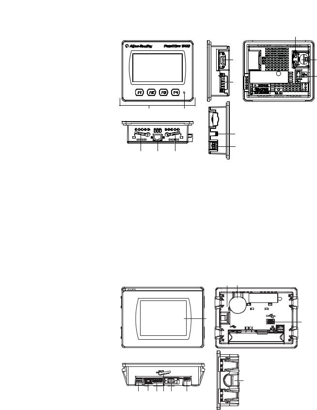
PanelView Component C400 Terminals
1 |
2 |
5 6 5
(C400 Series A terminal shown)
|
11 |
4 |
10 |
3 |
9 |
|
8
7
Item |
Description |
|
Item |
Description |
|
|
|
|
|
1 |
Touch, function keys display |
|
6 |
Mounting slots |
|
|
|
|
|
2 |
Power status indicator |
|
7 |
RS-232 serial port |
|
|
|
|
|
3 |
24V DC power input |
|
8 |
USB host port |
|
|
|
|
|
4 |
10/100 MBit Ethernet port |
|
9 |
Diagnostic status indicator |
|
|
|
|
|
5 |
RS-422 or RS-485 port |
|
10 |
Replaceable real-time clock battery |
|
|
|
|
|
PanelView Component C600 and C1000 Terminals
PanelView C600 |
1
6 |
1 |
2 |
3 |
4 |
5 |
6 |
7 |
(C600 Series C terminal shown)
8 |
9 |
FAULT |
|
10
B |
T T- R R- S |
11
12 |
Publication 2711C-UM001I-EN-P - July 2014 |

Overview |
Chapter 1 |
|
|
Item |
Description |
|
Item |
Description |
|
|
|
|
|
1 |
Touch display |
|
6 |
RS-232 serial port |
|
|
|
|
|
2 |
24V DC power input |
|
7 |
USB device port |
|
|
|
|
|
3 |
10/100 MBit Ethernet port |
|
8 |
Diagnostic status indicator |
|
|
|
|
|
4 |
RS-422 or RS-485 port |
|
9 |
Replaceable real-time clock battery |
|
|
|
|
|
5 |
Mounting slots (for 2711C-T6M, |
|
10 |
USB host port |
|
-T6C Series C or later, 2711C-T6T |
|
|
|
|
|
11 |
Secure digital (SD) card slot |
|
|
Series A or later only) |
|
||
|
|
|
|
|
|
|
|
|
|
|
|
|
|
|
IMPORTANT Analog touch screens are intended for single presses at a time. If the touch screen is pressed in two locations at the same time, the presses are averaged as a single press in-between the two locations.
How to Connect Browser |
The terminals can be connected to a browser using either a USB port or an |
|
Ethernet network connection. Your computer should have at least an Intel |
|
Pentium M 1400 MHz processor, with 512 MB RAM. |
|
You must enter the IP address of the PanelView Component terminal into the |
|
address field of your browser. You can find the IP address on the terminal |
|
configuration screen under Communications. |
|
USB Port |
|
The PanelView Component terminals have a USB device port to support |
|
communication with the terminal using TCP/IP. |
|
|
|
IMPORTANT Before connecting your computer to the USB port of the PanelView |
|
Component terminal, you must first install the Allen-Bradley |
|
PanelView USB remote NDIS Network Device driver on your |
|
computer. Refer to Install the USB Driver on page 65. |
|
|
|
With the USB device port connected to a computer, use your computer’s browser |
|
to connect to the terminal. The IP address of the USB port is always |
|
169.254.254.2. |
|
|
|
IMPORTANT The USB device port is for maintenance or programming only, and |
|
is not intended for normal run-time operation. |
|
|
Publication 2711C-UM001I-EN-P - July 2014 |
13 |

Chapter 1 |
Overview |
|
|
Ethernet Port
PanelView Explorer
How to Display Help
The C400, C600 and C1000 terminals have an Ethernet port. The Ethernet port supports both static IP addresses and Dynamic Host Configuration Protocol (DHCP) assigned IP addresses. If using static IP addressing, then you manually set the IP address, the subnet mask, and the default gateway. If using DHCP, then the server automatically assigns an IP address, the subnet mask, the default gateway, and the DNS and WINS server.
IMPORTANT If a terminal is set for DHCP and is not on a network or is on a network that does not have a DHCP server (or the server is not available), it will automatically assign itself an Automatic Private IP Address (or auto IP address). The auto IP address will be in the range of 169.254.0.0 through 169.254.255.255.
The terminal makes sure the auto IP address is unique from any other auto IP address of other devices on the network. The terminal can now communicate with other devices on the network that have IP addresses in the 169.254.xxx.xxx range (and a subnet mask of 255.255.0.0).
PanelView Explorer is the design environment for the PanelView Component terminals. You access the design environment through your browser while connected to the terminal. Applications created in the design environment are simultaneously viewed on the connected terminal. In addition to graphic objects and drawings, the design environment provides support for communication, tags, alarms, security, recipes, and language support.
PanelView Explorer software provides extensive help for the design environment. Context-sensitive help is available for:
•each navigation tab.
•each object in the object palette.
•any dialog that has a Help button.
Click the ? on the application toolbar to view the help.
No Help Files Found
To view help information in your browser, you must download the help files from the PanelView Component web site, copy them to external media, and then insert the media in the terminal. External media can be a USB flash drive or an SD memory card.
14 |
Publication 2711C-UM001I-EN-P - July 2014 |

Overview |
Chapter 1 |
|
|
Peripheral Connection
Terminal Users
Copy the help files to the WebHelp folder off the root directory of the SD memory card or USB flash drive into a folder named \WebHelp.
Emulator Users
Copy the help files to the WebHelp folder in the shared directory of the emulator, for example, C:\Documents and Settings\All Users\Shared Documents\Allen-Bradley\PanelView Component Emulator\WebHelp.
View Help Files
After copying the help files to external media and inserting the media in the terminal, you can view the help files by closing this help window and clicking the help ? button again.
TIP When receiving updated help files, you may have to clear cache in your browser before the new help files display.
View the PanelView Explorer online Help for detailed instructions.
PanelView Component terminals have a USB host port. You can power USB peripherals directly from the PanelView Component terminal. If the USB peripheral is not powered directly from the PanelView USB port either:
•install the USB peripheral in the same enclosure as the PanelView terminal and make sure it is connected to the same ground system.
•connect to the USB peripheral through a galvanically isolated hub.
ATTENTION: Removing the USB flash drive or SD card, from the PanelView Component terminal, while a firmware upgrade is in process, could corrupt the firmware and make the terminal unusable. Take precautions to prevent the USB flash drive or SD card from being accidentally disconnected. Also, do not power off the terminal while a firmware upgrade is in progress.
ATTENTION: USB hubs can produce unexpected behaviors and as a result are not recommended.
Publication 2711C-UM001I-EN-P - July 2014 |
15 |

Chapter 1 |
Overview |
|
|
Catalog Number
Configuration
These are the available PanelView Component terminals.
Cat. No. |
Model |
Operator Input |
Size |
Display Type |
|
|
|
|
|
2711C-F2M |
C200 |
Function keys |
2 in. |
Monochrome |
|
|
|
|
|
2711C-K2M |
|
Numeric and function keys |
|
|
|
|
|
|
|
2711C-T3M |
C300 |
Touch screen |
3 in. |
|
|
|
|
|
|
2711C-K3M |
|
Numeric and function keys |
|
|
|
|
|
|
|
2711C-T6M |
C600 |
Touch screen |
6 in. |
Monochrome |
|
|
|
|
|
2711C-T6C |
|
|
|
Color STN |
|
|
|
|
|
2711C-T6T |
|
|
|
Color TFT |
|
|
|
|
|
2711C-T10C |
C1000 |
Touch screen |
10 in. |
Color STN |
|
|
|
|
|
2711C-T4T |
C400 |
Touch screen and function |
4 in. |
Color TFT |
|
|
keys |
|
|
|
|
|
|
|
16 |
Publication 2711C-UM001I-EN-P - July 2014 |

Chapter 2
Configuration Mode
Chapter Objectives
Configuration Mode
This chapter covers topics that show how to use the Configuration mode of your PanelView component terminal.
•Configuration mode
•Configuration interfaces
•Terminal settings
•Managing applications and files
•Transferring applications
•Transferring user-defined objects
The terminal can be configured from either the design time or the runtime user interface. The design-time user interface requires a computer browser connected to the terminal's web service, where the runtime user interface uses configuration screens on the terminal. The configuration data for a terminal refers to the collection of all of the system interface parameters.
Access to the Terminal’s Configuration
Running
Internet Explorer or
Firefox browser
USB or Ethernet connectivity
On Terminal
Configuration 

Design-time Configuration
The design-time configuration is when the terminal is actually hosting web server content that represents a visualization of the terminal's properties and files. You can only design for the terminal type that you are connected to.
Publication 2711C-UM001I-EN-P - July 2014 |
17 |

Chapter 2 Configuration Mode
When a new application is created, the design time automatically navigates to the first screen and assigns it as the startup screen.
The design-time environment is compatible with these operating systems:
•Windows 2000 (catalog numbers 2711C-T4T, 2711C-T6M, 2711C-T6C, 2711C-T6T, and 2711C-T10C only, using an Ethernet connection to connect to the terminal)
•Windows XP
•Windows Vista
•Windows 7
TIP Connecting to a terminal using a USB connection is not compatible with Windows 2000 operating system.
The PanelView Component Emulator is not compatible with Windows 2000 operating system.
A user application can be created or edited through a browser connected to a terminal or emulator, or through PVc DesignStation. Ethernet network and USB connections are supported for connection to a physical terminal. For the emulator, the emulator and browser must be on the same computer.
Supported Browsers and Platforms
Operating System |
Browser |
Platform Supported |
|
|
|
|
|
Windows Vista (32 bit only) |
Internet Explorer 7/8, Firefox 3.0 |
Terminal and emulator |
|
Windows XP SP3 (32 bit only) |
|
|
|
|
|
|
|
Windows 7 |
Internet Explorer 7/8 |
PVc DesignStation 2.0 |
|
Windows Vista |
|
|
|
— |
PVc DesignStation 3.0 |
||
Windows XP SP3 |
|||
|
|
||
|
|
|
18 |
Publication 2711C-UM001I-EN-P - July 2014 |

Configuration Mode |
Chapter 2 |
|
|
If you use a browser other than a recommended browser, this message appears.
Runtime Configuration
The runtime configuration is when you make changes on the actual terminal.
Changes can be made whether an application is running or not running.
C200 |
C400, C600 and C1000 |
C300
Publication 2711C-UM001I-EN-P - July 2014 |
19 |
Chapter 2 Configuration Mode
Configuration Interfaces |
Terminal settings can be configured either on the terminal or through a web |
|
browser using the PanelView Explorer Startup window. |
Terminal Interface
The on-terminal interface lets you make changes to the terminal configuration. On the C200 and C300 terminals, you have to use the arrows to scroll through the menu. The C400, C600, and C1000 terminals have the menu displayed on the left side of the terminal screen.
C200 - Function Keys |
C300 - Touch Screen |
C400, C600, C1000 - Touch Screen |
|
|
C200 - Function and Numeric Keys |
C300 - Function and Numeric Keys |
20 |
Publication 2711C-UM001I-EN-P - July 2014 |
Configuration Mode |
Chapter 2 |
|
|
PanelView Explorer Startup Window
The PanelView Explorer Startup window lets you access the terminal through a web browser.
10 |
1 |
2 |
3 |
4
9
|
8 |
|
|
|
5 |
|
|
|
|
||
|
7 |
|
|
|
6 |
|
|
|
|
|
|
PanelView Explorer Startup Window |
|
||||
|
|
|
|
|
|
Item |
|
|
Function |
Description |
|
|
|
|
|
|
|
1 |
|
|
Terminal Settings |
Use this link to view and change terminal display and communication settings, view |
|
|
|
|
|
|
system information, and enable terminal security while connected to the terminal. |
|
|
|
|
|
|
2 |
|
|
File Transfer |
Transfers files between the storage media of the terminal and your computer. You can |
|
|
|
|
|
|
transfer applications, images, fonts, user-defined objects, screen saver bitmaps and |
|
|
|
|
|
recipes. You can also delete applications from terminal storage and export the alarm |
|
|
|
|
|
history log. |
|
|
|
|
|
|
3 |
|
|
Help |
Displays help for the PanelView Explorer startup window and the design-time software. |
|
|
|
|
|
|
|
4 |
|
|
Sign off |
Logs you off the Startup window leaving your browser open. |
|
|
|
|
|
|
|
5 |
|
|
Terminal Type and Status |
Shows the current connection between your PanelView Component terminal and |
|
|
|
|
|
|
computer and the type of terminal. |
|
|
|
|
|
|
6 |
|
|
Language |
Shows the current and available languages for the design-time software. |
|
|
|
|
|
|
|
7 |
|
|
Create New Application |
Opens a new application in the design-time environment window. |
|
|
|
|
|
|
|
8 |
|
|
Edit, Test, Run |
Use these buttons to edit, test, and run the currently loaded application. |
|
|
|
|
|
|
|
9 |
|
|
Available Applications |
Shows a list of applications stored on the terminal, USB memory, SD card, or PC Storage |
|
|
|
|
|
|
on the emulator. The list also shows if the file has been validated for correct operation. |
|
|
|
|
|
|
10 |
|
|
Stop |
Click the Stop button (the stop sign shown when an app is loaded and in Edit/Test/Run |
|
|
|
|
|
|
mode) to unload the currently loaded application. If you have not saved changes to the |
|
|
|
|
|
application, you are prompted to do so. Once the application is unloaded, the terminal |
|
|
|
|
|
displays the Configuration screen. |
|
|
|
|
|
|
Publication 2711C-UM001I-EN-P - July 2014 |
21 |
Chapter 2 Configuration Mode
Terminal Settings
Terminal settings can be set on the terminal or through the PanelView Explorer Startup window.
Adjusting Settings on the Terminal
From the terminal, you can view and edit the terminal settings. The settings take effect immediately.
By clicking the menu items on the screen you can:
•switch to the currently running application.
•configure the terminal language.
•change the current application.
•adjust the display brightness and contrast.
•configure screen saver settings.
•calibrate the touch screen, if supported.
•reboot or reset the terminal.
•view system information.
•change the startup application.
•change the current date and time.
•set Ethernet network communication.
Terminal Main Menu
C200 |
C400, C600 and C1000 |
C300
These settings can also be changed using the PanelView Explorer Startup Window.
22 |
Publication 2711C-UM001I-EN-P - July 2014 |
Configuration Mode |
Chapter 2 |
|
|
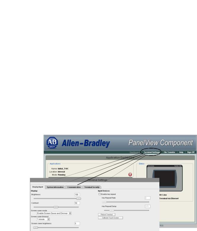
Adjusting Settings on the PanelView Explorer Startup Window
From the PanelView Explorer Startup window, you can view and edit settings for the connected PanelView Component terminal. The settings take effect immediately.
By clicking the Terminal Settings link on the PanelView Explorer Startup window, you can access tabs to:
•adjust the display brightness and contrast.
•configure screen saver settings.
•configure key repeat settings.
•calibrate the touch screen (if supported).
•reset the terminal.
•view system information.
•change the startup application.
•change the terminal language.
•change the current date and time.
•Ethernet communication.
•change the password of the system administrator.
Most of these settings are also adjusted from configuration mode on the terminal.
|
|
|
Publication 2711C-UM001I-EN-P - July 2014 |
23 |
|

Chapter 2 Configuration Mode
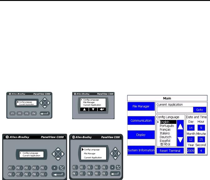
Select a Terminal Language
You can change the terminal display language. The terminal is shipped with the English, Portuguese, French, Italian, German, Spanish, and Chinese fonts installed. Korean is available but you must first install the Korean font. Refer to page 76 for information on how to install the font by upgrading the firmware.
Follow these steps to change the terminal language using the PanelView Explorer Startup window.
1.Go to the PanelView Explorer Startup window.
2.Click the Terminal Settings link.
3.Click the System Information tab.
4.Select a language from the Terminal Language pull-down list.
5. Click Apply or click Cancel to restore the current setting.
On the C400, C600 and C1000 terminals the default language is set on the Main menu. Just click the up and down arrows to select the language.
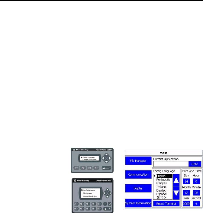
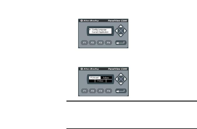
Follow these steps to change the language on the C200 and C300 terminals.
24 |
Publication 2711C-UM001I-EN-P - July 2014 |
Configuration Mode |
Chapter 2 |
|
|
1. Click Config Language.
2.Press F1 to select the language.
The display changes to the language you select immediately.
IMPORTANT At runtime, diagnostic messages appear in the same language as the application if the application language is English, Portuguese, French, Italian, German, Spanish, Chinese, or Korean. For all other languages, the diagnostic messages appear in the configuration language set on the terminal.
Adjust the Display Brightness and Contrast
You can modify the brightness and contrast of the terminal display. You can use the default intensity of 50% for contrast and 100% for brightness or adjust the intensity for runtime operations.
TIP On the C400 (2711C-T4T), C600 (2711C-T6T) and C1000 terminals, only the brightness can be changed.
Follow these steps to change the display brightness and contrast using the
PanelView Explorer Startup window.
1.Go to the PanelView Explorer Startup window.
2.Click the Terminal Settings link.
3.Click the Display/Input tab.
4.Drag the slider to adjust the brightness level between 1…100%.
5.Drag the slider to adjust the contrast level between 1…100%.
6.Click Apply, or click Cancel to restore the current terminal settings.
Publication 2711C-UM001I-EN-P - July 2014 |
25 |

Chapter 2 Configuration Mode
Follow these steps to change the display brightness or contrast from the terminal.
1. Click Display on the menu list.
C200, C300 |
C400, C600, C1000 |
2.Use the arrow keys to adjust the brightness or contrast up or down.
On the C200 and C300 terminals, press F3 to go to the contrast adjustment screen. The change takes effect immediately.
TIP The C400 (2711C-T4T), C600 (2711C-T6T) and C1000 have only a brightness control.
C200, C300 Brightness
C400 and C600 Brightness and Contrast
C200, C300 Contrast
26 |
Publication 2711C-UM001I-EN-P - July 2014 |

Configuration Mode |
Chapter 2 |
|
|
Configure the Screen Saver
You can enable or disable the screen saver on the connected PanelView
Component terminal.
The terminal has four screen saver modes: screen saver, dimmer, screen saver and dimmer, or disable.
•Screen saver – activates after the idle timeout elapses using a default screen saver image. The screen saver deactivates when you press a key.
•Dimmer – dims the display from full brightness to the brightness level you set when the idle timeout elapses. While the display is dimmed, you can still see on-screen activity. When you press a key, the display is restored to full brightness.
•Screen saver and dimmer – activates the screen saver and dims the display when the idle timeout elapses.
•Disable screen saver and dimmer – keeps the display on.
The screen saver timeout is the amount of idle time that must elapse before the screen saver, dimmer, or screen saver and dimmer activates. The idle time can be adjusted between 1…60 minutes.
The brightness intensity of the screen saver or dimmer can be adjusted between 1…100%.
Follow these steps to configure the screen saver using the PanelView Explorer
Startup window.
1.Go to the PanelView Explorer Startup window.
2.Click the Terminal Settings link.
3.Click the Display/Input tab.
4.Select a screen saver mode from the list.
5. Select a time from the pull-down list to adjust the screen saver timeout.
Publication 2711C-UM001I-EN-P - July 2014 |
27 |

Chapter 2 Configuration Mode
6.Drag the slider to adjust the screen saver brightness.
7.Click Apply, or click Cancel to restore the current screen saver settings.
To disable the screen saver or dimmers, select Disable Screen Saver and Dimmer from the screen saver mode list.
Follow these steps to configure the screen saver from the C400, C600 and C1000 terminals.
1.Click Display on the menu list.
2.Select the Mode.
Mode = Image, Disable, Dimmer, Image and Dimmer.
3.Select the brightness.
Brightness 1…100, increments of 1.
4.Select the idle time.
Choices are 1, 2, 5, 10, 15, 20, 30, or 60 min.
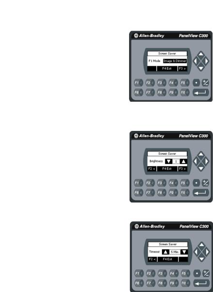
Follow these steps to configure the screen saver from the C200 and C300 terminals.
1. Select Screen Saver on the menu list and press the enter key.
2. Press F1 to select the Mode.
28 |
Publication 2711C-UM001I-EN-P - July 2014 |
Configuration Mode |
Chapter 2 |
|
|
Mode = Image, Disable, Dimmer, Image and Dimmer.
3.Press F3 and use the arrows to select the brightness. Brightness 1…100, increments of 1.
4. Press F3 to get to the Timeout selection.
5.Press F1 to select the time.
Choices are 1, 2, 5, 10, 15, 20, 30, or 60 min.
Replace the Screen Saver Image
The default screen saver image is a floating Allen-Bradley logo in a bitmap format. The name of the default screen saver is 'Screen Saver' with a .bmp file type. You can replace the default screen saver with your own bitmap image, but the file must have the same name as the default screen saver.
To replace the screen saver image:
1. Create a small bitmap image no larger than 128 x 128 pixels.
Publication 2711C-UM001I-EN-P - July 2014 |
29 |

Chapter 2 Configuration Mode
2.Save your bitmap file to your computer, a USB drive or and SD card. Rename your file as 'Screen Saver' and make sure the file type is .bmp.
3.Click the File Transfer link in the PanelView Explorer Startup window, then click New Transfer.
4.Select either My Computer or USB/SD Storage as file source depending on where you saved your file, then click Next.
5.Select Screen Saver Image as the file type, then click Next.
6.Locate where you saved your bitmap file on your computer or external storage device.
7.Select Internal Storage as file destination, then click Transfer. The bitmap file is successfully transferred to the PVc terminal.
The new screen saver takes affect the next time the screen saver is activated.
TIP |
Your bitmap file should be small in size. A large bitmap will |
|
impact performance of terminal operations. |
Configure Key Repeat Settings
You can configure key repeat settings for the terminal keys or attached keyboard of the connected terminal.
TIP You cannot change the key repeat settings from the on-terminal configuration screens. If you want to change this setting, you must connect to the terminal through a web browser.
30 |
Publication 2711C-UM001I-EN-P - July 2014 |
Loading...