


20D-700S
Installation Instructions
PowerFlex 700S Adjustable Frequency Drive - Phase II Control
Frames 1…6
0.75…132 kW (1…200 Hp)
Introduction
This document explains the 5 primary steps for mechanical installation and for
connecting incoming power, the motor, and basic I/O to the PowerFlex® 700S
adjustable frequency AC drive with Phase II control.
The information provided is intended for qualified installers only.
The Additional Resources section on page 5
Automation publications that provide detailed drive information from wiring
and grounding recommendations to troubleshooting and repair.
ATTENTION: This product contains a 3V Lithium battery if the DriveLogix
Controller option board is installed. Perchlorate Material - special handling may
apply.
See www.dtsc.ca.gov/hazardouswaste/perchlorate
is a directory of Rockwell
Publication 20D-IN024C-EN-P - July 2013

PowerFlex 700S Adjustable Frequency AC Drive - Phase II Control
2 Rockwell Automation Publication 20D-IN024C-EN-P - July 2013

PowerFlex 700S Adjustable Frequency AC Drive - Phase II Control
Table of Contents
Additional Resources . . . . . . . . . . . . . . . . . . . . . . . . . . . . . . . . . . . . . . . . . . . . . . . . . . 5
Step 1: Read the General Precautions
Qualified Personnel . . . . . . . . . . . . . . . . . . . . . . . . . . . . . . . . . . . . . . . . . . . . . . . . . . . . . . 6
Personal Safety. . . . . . . . . . . . . . . . . . . . . . . . . . . . . . . . . . . . . . . . . . . . . . . . . . . . . . . . . . . 6
Product Safety . . . . . . . . . . . . . . . . . . . . . . . . . . . . . . . . . . . . . . . . . . . . . . . . . . . . . . . . . . . 7
Class 1 LED Product . . . . . . . . . . . . . . . . . . . . . . . . . . . . . . . . . . . . . . . . . . . . . . . . . . . . . 7
Step 2: Prepare for Installation
Catalog Number Explanation . . . . . . . . . . . . . . . . . . . . . . . . . . . . . . . . . . . . . . . . . . . . . 8
Drive Rating to Frame Size Cross References . . . . . . . . . . . . . . . . . . . . . . . . . . . . . .10
CE Conformity . . . . . . . . . . . . . . . . . . . . . . . . . . . . . . . . . . . . . . . . . . . . . . . . . . . . . . . . . 12
Common Bus and Precharge Considerations . . . . . . . . . . . . . . . . . . . . . . . . . . . . . . 14
Operating Conditions and Temperatures. . . . . . . . . . . . . . . . . . . . . . . . . . . . . . . . . . 14
Minimum Mounting Clearances. . . . . . . . . . . . . . . . . . . . . . . . . . . . . . . . . . . . . . . . . . 15
Approximate Dimensions . . . . . . . . . . . . . . . . . . . . . . . . . . . . . . . . . . . . . . . . . . . . . . . . 16
Step 3: Lift and Mount the Drive
Drive Weights . . . . . . . . . . . . . . . . . . . . . . . . . . . . . . . . . . . . . . . . . . . . . . . . . . . . . . . . . . 22
Attaching the Lifting Hardware . . . . . . . . . . . . . . . . . . . . . . . . . . . . . . . . . . . . . . . . . . 22
Step 4: Power Wiring
Grounding Requirements . . . . . . . . . . . . . . . . . . . . . . . . . . . . . . . . . . . . . . . . . . . . . . . . 25
Shield Termination - SHLD. . . . . . . . . . . . . . . . . . . . . . . . . . . . . . . . . . . . . . . . . . . . . . 25
Unbalanced, Ungrounded or Resistive Grounded Distribution Systems . . . . . . 26
RFI Filter Ground. . . . . . . . . . . . . . . . . . . . . . . . . . . . . . . . . . . . . . . . . . . . . . . . . . . . . . . 26
Power Jumpers . . . . . . . . . . . . . . . . . . . . . . . . . . . . . . . . . . . . . . . . . . . . . . . . . . . . . . . . . . 27
AC Input Phase Selection (Frames 5 and 6 Only) . . . . . . . . . . . . . . . . . . . . . . . . . . 33
Selecting/Verifying Fan Voltage (Frames 5 and 6 Only) . . . . . . . . . . . . . . . . . . . . . 34
Important Common Bus (DC Input) Application Notes . . . . . . . . . . . . . . . . . . . 36
Auxiliary Control Power Supply. . . . . . . . . . . . . . . . . . . . . . . . . . . . . . . . . . . . . . . . . . 36
Accessing the Terminals. . . . . . . . . . . . . . . . . . . . . . . . . . . . . . . . . . . . . . . . . . . . . . . . . . 37
Power Wire Recommendations. . . . . . . . . . . . . . . . . . . . . . . . . . . . . . . . . . . . . . . . . . . 39
Power Terminal Block Specifications. . . . . . . . . . . . . . . . . . . . . . . . . . . . . . . . . . . . . . 39
Dynamic Brake Resistor Considerations . . . . . . . . . . . . . . . . . . . . . . . . . . . . . . . . . . 42
Using Input/Output Contactors . . . . . . . . . . . . . . . . . . . . . . . . . . . . . . . . . . . . . . . . . 43
Using PowerFlex 700S Drives with Regenerative Power Units . . . . . . . . . . . . . . . 43
Regenerative Unit to Drive Connections . . . . . . . . . . . . . . . . . . . . . . . . . . . . . . . . . . 44
Fusing and Circuit Breakers. . . . . . . . . . . . . . . . . . . . . . . . . . . . . . . . . . . . . . . . . . . . . . 44
Rockwell Automation Publication 20D-IN024C-EN-P - July 2013 3

PowerFlex 700S Adjustable Frequency AC Drive - Phase II Control
Step 5: Control and I/O Wiring
Control and I/O Wiring Recommendations. . . . . . . . . . . . . . . . . . . . . . . . . . . . . . . 52
Main Control Board DIP Switch Settings . . . . . . . . . . . . . . . . . . . . . . . . . . . . . . . . . 53
Hardware Enable Circuitry . . . . . . . . . . . . . . . . . . . . . . . . . . . . . . . . . . . . . . . . . . . . . . 54
I/O Terminals . . . . . . . . . . . . . . . . . . . . . . . . . . . . . . . . . . . . . . . . . . . . . . . . . . . . . . . . . . 55
I/O Wiring Examples . . . . . . . . . . . . . . . . . . . . . . . . . . . . . . . . . . . . . . . . . . . . . . . . . . . 57
DriveLogix 5730 Controller Option. . . . . . . . . . . . . . . . . . . . . . . . . . . . . . . . . . . . . . 61
DriveGuard® Safe Torque Off with Second Encoder Option . . . . . . . . . . . . . . . . 61
Second Encoder Feedback Option. . . . . . . . . . . . . . . . . . . . . . . . . . . . . . . . . . . . . . . . 62
Stegmann Hi-Resolution Encoder Feedback Option . . . . . . . . . . . . . . . . . . . . . . . 64
Resolver Feedback Option . . . . . . . . . . . . . . . . . . . . . . . . . . . . . . . . . . . . . . . . . . . . . . . 70
Multi-Device Interface (MDI) Feedback Option. . . . . . . . . . . . . . . . . . . . . . . . . . . 73
4 Rockwell Automation Publication 20D-IN024C-EN-P - July 2013
PowerFlex 700S Adjustable Frequency AC Drive - Phase II Control
Additional Resources
These documents contain additional information concerning related products
from Rockwell Automation.
Resource Description
PowerFlex 700S Drives with Phase II Control
Programming Manual, publication 20D-PM001
PowerFlex 7-Class HIM (DPI) Quick Reference,
publication 20HIM-QR001
PowerFlex 700S Drives with Phase II Control Reference
Manual, publication PFLEX-RM003
DriveLogix5730 Controller for PowerFlex 700S Drives
with Phase II Control User Manual,
publication 20D-UM003
DriveGuard® Safe-Off Option for PowerFlex 700S
Drives with Phase II Control, publication 20D-UM007
Wiring and Grounding Guidelines for Pulse Width
Modulated (PWM) AC Drives,
publication DRIVES-IN001
PowerFlex AC Drives in Common Bus Configurations,
publication DRIVES-AT002
Safety Guidelines for the Ap plication, Installation and
Maintenance of Solid State Control,
publication SGI-1.1
A Global Reference Guide for Reading Schematic
Diagrams, publication 100-2.10
Guarding Against Electrostatic Damage,
publication 8000-4.5.2
Product Certifications website, http://www.ab.com
Provides the following detailed information:
• Drive start-up instructions
• Parameters and programming
• Faults, alarms, and troubleshooting
• Human Interface Module (HIM) Operation Instructions
Provides a quick reference guide for using the PowerFlex 7Class HIM.
Provides detailed control functions and application
programming examples.
Provides instructions for developing DriveLogix controller
projects.
Provides information and instructions for properly planning
for and installing the DriveGuard Safe Torque Off option board.
Provides basic information needed to properly wire and
ground PWM AC drives.
Provides basic information needed to properly wire and
ground PWM AC drives using a common DC bus.
Provides general guidelines for the application, installation,
and maintenance of solid-state control.
Provides a simple cross-reference of common schematic/
wiring diagram symbols used throughout various parts of the
world.
Provides practices for guarding against Electrostatic damage
(ESD)
Provides declarations of conformity, certificates, and other
certification details.
You can view or download publications at
http://www.rockwellautomation.com/literature/
. To order paper copies of
technical documentation, contact your local Allen-Bradley distributor or
Rockwell Automation sales representative.
Rockwell Automation Publication 20D-IN024C-EN-P - July 2013 5
PowerFlex 700S Adjustable Frequency AC Drive - Phase II Control
Step 1: Read the General
Precautions
ATTENTION: Only qualified personnel familiar with adjustable frequency AC drives and associated machinery should plan or
implement the installation, startup and subsequent maintenance of the system. Failure to comply may result in personal injury
and/or equipment damage.
ATTENTION: To avoid an electric shock hazard, verify that the voltage on the bus capacitors has discharged before per forming any
work on the drive. Measure the DC bus voltage at the +DC and –DC terminals of the Power Terminal Block (refer to page 40
location). The voltage must be zero.
ATTENTION: Hazard of personal injury or equipment damage exists when using bipolar input sources. Noise and drift in sensitive
input circuits can cause unpredictable changes in motor speed and direction. Use speed command parameters to help reduce input
source sensitivity.
ATTENTION: Risk of injury or equipment damage exists. DPI or SCANport host products must not be directly connected together
via 1202 cables. Unpredictable behavior can result if two or more devices are connected in this manner.
Qualified Personnel
Personal Safety
for
ATTENTION: The drive start/stop/enable control circuitry includes solid state components. If hazards due to accidental contact
with moving machinery or unintentional flow of liquid, gas or solids exists, an additional hardwired stop circuit may be required to
remove the AC line to the drive. An auxiliary braking method may be required.
ATTENTION: Hazard of personal injury or equipment damage due to unexpected machine operation exists if the drive is
configured to automatically issue a Start or Run command. Do not use these functions without considering applicable local,
national and international codes, standards, regulations or industry guidelines.
ATTENTION: Parameters 365 [Encdr0 Loss Cnfg] - 394 [VoltFdbkLossCnfg] let you determine the action of the drive in response to
operating anomalies. Precautions should be taken to be sure that the settings of these parameters do not create hazards of
personal injury or equipment damage.
ATTENTION: Parameters 383 [SL CommLoss Data] - 392 [NetLoss DPI Cnfg] let you determine the action of the drive if
communications are disrupted. You can set these parameters so the drive continues to run. Precautions should be taken to ensure
the settings of these parameters do not create hazards of personal injury or equipment damage.
ATTENTION: This product contains a 3V Lithium battery if the DriveLogix Controller option board is installed. Perchlorate Material special handling may apply.
See www.dtsc.ca.gov/hazardouswaste/perchlorate
6 Rockwell Automation Publication 20D-IN024C-EN-P - July 2013

PowerFlex 700S Adjustable Frequency AC Drive - Phase II Control
Product Safety
ATTENTION: An incorrectly applied or installed drive can result in component damage or a reduction in product life. Wiring or
application errors such as under sizing the motor, incorrect or inadequate AC supply, or excessive surrounding air temperatures may
result in malfunction of the system.
ATTENTION: This drive contains ESD (Electrostatic Discharge) sensitive parts and assemblies. Static control precautions are
required when installing, testing, servicing or repairing this assembly. Component damage may result if ESD control procedures are
not followed. If you are not familiar with static control procedures, reference Guarding Against Electrostatic Damage, publication
8000-4.5.2 or any other applicable ESD protection handbook.
ATTENTION: Configuring an analog input for 0-20 mA operation and driving it from a voltage source could cause component
damage. Verify proper configuration prior to applying input signals.
ATTENTION: A contactor or other device that routinely disconnects and reapplies the AC line to the drive to start and stop the
motor can cause drive hardware damage. The drive is designed to use control input signals that will start and stop the motor. If an
input device is used, operation must not exceed one cycle per minute or drive damage will occur.
Class 1 LED Product
ATTENTION: Hazard of permanent eye damage exists when using optical transmission equipment. This product emits intense
light and invisible radiation. Do not look into module ports or fiber optic cable connectors.
Rockwell Automation Publication 20D-IN024C-EN-P - July 2013 7
PowerFlex 700S Adjustable Frequency AC Drive - Phase II Control
Step 2: Prepare for
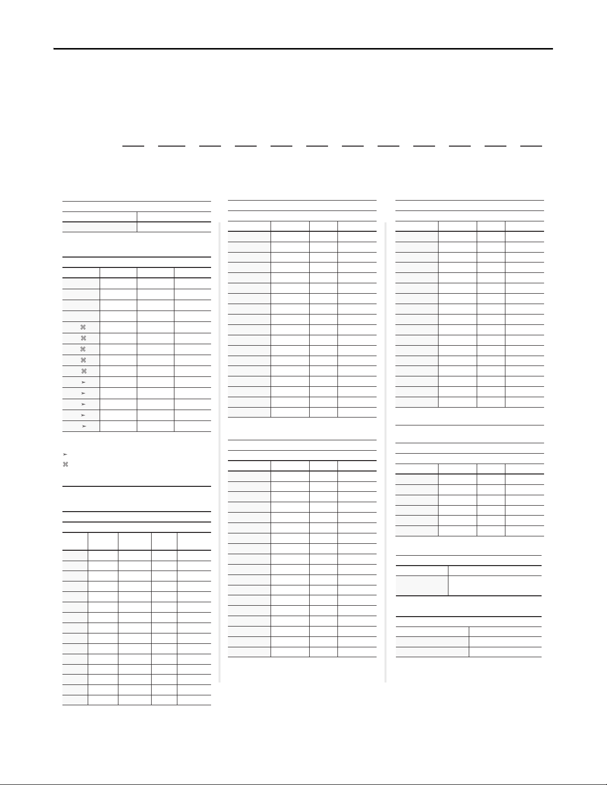
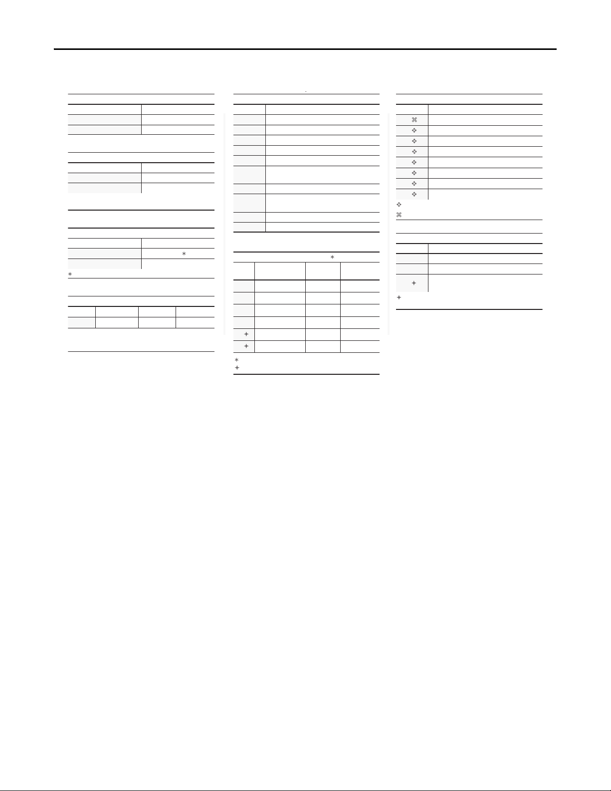
Catalog Number Explanation
Installation
Position
1-3 4 5-7 8 9 10 11 12 13 14 15 16 17
20D D 2P1 A 0 E Y N A N A N E
abcdefghijklm
a
Drive
Code Type
20D PowerFlex 700S
b
Voltage Rating
Code Voltage Ph. Prechg.
B §
240V AC
C §
400V AC
D §
480V AC
E ♣ §
F
H
J
K
M
N
P
R
T
W
♣ Note: CE Certication testing has not been
performed on 600V class drives, Frames 1…4.
Frames 5 & 6 only.
Frames 5 & 6 only.
§ For DC input on Frames 1…4, use the
corresponding AC input code B, C, D, or E.
600V AC
690V AC
540V DC
650V DC
810V DC
932V DC
325V DC
540V DC
650V DC
810V DC
932V DC
3 (6 pulse)
3 (6 pulse)
3 (6 pulse)
3 (6 pulse)
3 (6 pulse)
_
_
_
_
_
_
_
_
_
c1
ND Rating
208/240V, 60Hz Input
Code
4P2
6P8
9P6
015
022
028
042
052
070
080
104
130
154
192
260
208V
Amps
17.5
25.3
32.2
48.3
78.2
120
130
177
221
260
4.8
7.8
240V
Amps
4.2
6.8
11
56
92
9.6
15.3
22
28
42
52
70
80
104
130
154
192
260
Hp
1.0
2.0
3.0
5.0
7.5
10
15
20
25
30
40
50
60
75
100
_
_
_
_
_
N
N
N
N
Y
Y
Y
Y
Y
Frame
1
1
1
1
1
2
3
3
4
4
5
5
6
6
6
c2
ND Rating
400V, 50 Hz Input
Code Amps kW
2P1
3P5
5P0
8P7
011
015
022
030
037
043
056
072
085
105
125
170
205
260
2.1
3.5
5.0
8.7
11.5
15.4
22
30
37
43
56
72
85
105
125
170
205
260
0.75
1.5
2.2
4.0
5.5
7.5
18.5
110
132
c3
ND Rating
480V, 60 Hz Input
Code Amps Hp
2P1
3P4
5P0
8P0
011
014
022
027
034
040
052
065
077
096
125
156
180
248
2.1
3.4
5
8
11
14
22
27
34
40
52
65
77
96
125
156
180
248
1.0
2.0
3.0
5.0
7.5
100
125
150
200
Frame
1
1
1
1
1
1
11
15
22
30
37
45
55
55
90
10
15
20
25
30
40
50
60
75
1
2
2
3
3
3
4
5
5
6
6
6
Frame
1
1
1
1
1
1
1
2
2
3
3
3
4
5
5
6
6
6
Code Amps Hp
1P7
2P7
3P9
6P1
9P0
011
017
022
027
032
041
052
062
077
099
125
144
♣ Note: CE Certication testing has not been
performed on 600V class drives Frames 1…4.
Code Amps kW
052
060
082
098
119
142
Code
A
Code Operator Interface
0 Blank Cover
3 Full Numeric LCD
c4
ND Rating
600V, 60 Hz Input
1.7
2.7
3.9
6.1
9
11
17
22
27
32
41
52
62
77
99
125
144
c5
ND Rating
690V, 50 Hz Input
52
60
82
98
119
142
d
Enclosure
Description
IP20, NEMA Type 1
with Conformal Coat
e
HIM
♣
0
2
3
5
7.5
10
15
20
25
30
40
50
60
75
100
125
150
45
55
75
90
110
132
Frame
1
1
1
1
1
1
1
2
2
3
3
3
4
5
5
6
6
Frame
5
5
5
5
6
6
8 Rockwell Automation Publication 20D-IN024C-EN-P - July 2013
PowerFlex 700S Adjustable Frequency AC Drive - Phase II Control
Feedback
Code Option
N
Standard (Incremental Encoder)
A
Resolver
B
Stegmann Hi-Resolution Encoder
C
Multi-Device Interface
E
2nd Encoder
S
Safe-O (w/2nd Encoder)
Expanded cassette required.
One encoder interface included with base drive.
m
Additional Cong.
Code Description
E Phase II Control
K Phase II DriveLogix5730
L
Phase II DriveLogix5730
w/EtherNet/IP
This is an embedded EtherNet/IP option that is
only available with DriveLogix5730.
T
Stegmann Hi-Res Enc. (w/2nd Encoder)
U
Stegmann Hi-Res Enc. (w/Safe-O)
Documentation
Code Documents
N No Documentation
g
Brake
Code w/Brake IGBT ‡
seYY
oNN
‡ Brake IGBT is standard on Frames 1…3 and
optional on Frames 4…9 ONLY.
h
Brake Resistor
Code w/Resistor
Y Ye s
oNN
Not available for Frame 3 drives or larger.
English ManualE
j
Comm Slot
Code Version
N None
C DPI ControlNet (Coax)
D DPI DeviceNet
E DPI EtherNet/IP
1 DriveLogix ControlNet (Coax)
2
DriveLogix ControlNet Redundant
(Coax)
3 DriveLogix ControlNet (Fiber)
4
DriveLogix ControlNet Redundant
(Fiber)
5 DriveLogix DeviceNet (Open Conn.)
6 DriveLogix EtherNet/IP
i
Emission
Code
CE Filter ♣
CM Choke
A
♣ Note: CE Certication testing has not been
performed on 600V class drives Frames 1…4.
Ye sYe s
du/dt Filter
No
k
Control Options
Code Cassette
A
Phase II Contol available only.
B
C
D
G
H
Logix Expansion Synchlink
No Expanded
Slim
No
No ExpandedYes
Yes ExpandedNo
Yes ExpandedYes
NoN/A
SlimYesN/A
Frames 1...9 only.
Catalog Number Explanation, Continued
Rockwell Automation Publication 20D-IN024C-EN-P - July 2013 9

PowerFlex 700S Adjustable Frequency AC Drive - Phase II Control
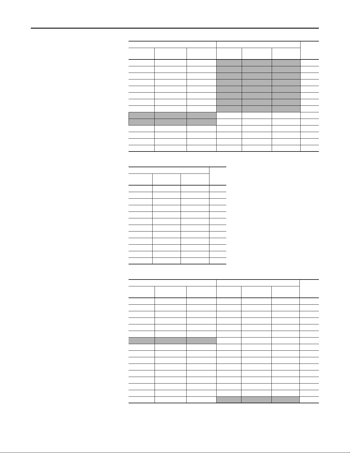
Drive Rating to Frame Size Cross References
Table 1 - 208/240 Volt AC Input, Six Pulse Drives
208V AC Input
Cat. No. Normal Duty
20DB4P2 0.75 0.55 20DB4P2 1 0.75 1
20DB6P8 1.5 1.1 20DB6P8 2 1.5 1
20DB9P6 2.2 1.5 20DB9P6 3 2 1
20DB015 4.0 3.0 20DB015 5 3 1
20DB022 5.5 4.0 20DB022 7.5 5 1
20DB028 7.5 5.5 20DB028 10 7.5 2
20DB042 11 7.5 20DB042 15 10 3
20DB052 15 11 20DB052 20 15 3
20DB070 18.5 15 20DB070 25 20 4
20DB080 22 18.5 20DB080 30 25 4
20DB104 30 22 20DB104 40 30 5
20DB130 37 30 20DB130 50 40 5
20DB154 45 37 20DB154 60 50 6
20DB192 55 45 20DB192 75 60 6
20DB260 66 55 20DB260 100 75 6
(1) The drive must be programmed to this voltage.
(1)
kW Rating
Heavy Duty kW
Rating
240V AC Input Frame
Cat. No. Normal Duty
Hp Rating
Heavy Duty Hp
Rating
Size
Table 2 - 400/480 Volt AC Input, Six Pulse Drives
400V AC Input 480V AC Input Frame
Cat. No. Normal Duty kW
Rating
20DC2P1 0.75 0.55 20DD2P1 1.0 0.75 1
20DC3P5 1.5 1.1 20DD3P4 2.0 1.5 1
20DC5P0 2.2 1.5 20DD5P0 3.0 2.0 1
20DC8P7 4.0 3.0 20DD8P0 5.0 3.0 1
20DC011 5.5 4.0 20DD011 7.5 5.0 1
20DC015 7.5 5.5 20DD014 10 7.5 1
20DC022 11 7.5 20DD022 15 10 1
20DC030 15 11 20DD027 20 15 2
20DC037 18.5 15 20DD034 25 20 2
20DC043 22 18.5 20DD040 30 25 3
20DC056 30 22 20DD052 40 30 3
20DC072 37 30 20DD065 50 40 3
20DC085 45 37 20DD077 60 50 4
20DC105 55 45 20DD096 75 60 5
20DC125 55 45 20DD125 100 75 5
20DC140 75 55
20DC170 90 75 20DD156 125 100 6
20DC205 110 90 20DD180 150 125 6
20DC260 132 110 20DD248 200 150 6
Heavy Duty kW
Rating
Cat. No. Normal Duty
Hp Rating
Heavy Duty Hp
Rating
Size
5
Table 3 - 600/690 Volt AC Input, Six Pulse Drives
600V AC Input 690V AC Input Frame
Cat. No. Normal Duty Hp
Rating
20DE1P7 1.0 0.75
20DE2P7 2.0 1.5
20DE3P9 3.0 2.0
20DE6P1 5.0 3.0
20DE9P0 7.5 5.0
Heavy Duty Hp
Rating
Cat. No. Normal Duty
kW Rating
Heavy duty
kW Rating
Size
1
1
1
1
1
10 Rockwell Automation Publication 20D-IN024C-EN-P - July 2013
PowerFlex 700S Adjustable Frequency AC Drive - Phase II Control
600V AC Input 690V AC Input Frame
Cat. No. Normal Duty Hp
Rating
20DE011 10 7.5 1
20DE017 15 10
20DE022 20 15 2
20DE027 25 20
20DE032 30 25
20DE041 40 30
20DE052 50 40 3
20DE062 60 50 4
20DE077 75 60 20DF082 75 55 5
20DE099 100 75 20DF098 90 75 5
20DE125 125 100 20DF119 110 90 6
20DE144 150 125 20DF142 132 110 6
Heavy Duty Hp
Rating
Cat. No. Normal Duty
kW Rating
20DF052 45 37.5 5
20DF060 55 45 5
Heavy duty
kW Rating
Size
1
2
3
3
Table 4 - 325 Volt DC Input, Six Pulse Drives
325V DC input Frame
Cat. No. Normal Duty
Hp Rating
20DB015 5.0 3.0 1
20DB022 7.5 5.0 1
20DB028 10 7.5 2
20DB042 15 10 3
20DB052 20 15 3
20DB070 25 20 4
20DB080 30 25 4
20DN104 40 30 5
20DN130 50 40 5
20DN154 60 50 6
20DN192 75 60 6
20DN260 100 75 6
Heavy Duty Hp
Rating
Size
Table 5 - 540/650 Volt DC Input Drives
540V DC Input 650V DC Input Frame
Cat. No. Normal Duty kW
Rating
20DC3P5 1.5 1.1 20DD2P1 1.0 0.75 1
20DC5P0 2.2 1.5 20DD3P4 2.0 1.5 1
20DC8P7 4.0 3.0 20DD5P0 3.0 2.0 1
20DC011 5.5 4.0 20DD8P0 5.0 3.0 1
20DC015 7.5 5.5 20DD011 7.5 5.0 1
20DC022 11 7.5 20DD014 10 7.5 1
20DC030 15 11 20DD027 20 15 2
20DC037 18.5 15 20DD034 25 20 2
20DC043 22 18.5 20DD040 30 25 3
20DC056 30 22 20DD052 40 30 3
20DC072 37 30 20DD065 50 40 3
20DC085 45 37 20DD077 60 50 4
20DH105 55 45 20DJ096 75 60 5
20DH125 55 45 20DJ125 100 75 5
20DH140 75 55
Rockwell Automation Publication 20D-IN024C-EN-P - July 2013 11
Heavy Duty kW
Rating
Cat. No. Normal Duty
HP Rating
20DD022 15 10 1
Heavy Duty
HP Rating
Size
5

PowerFlex 700S Adjustable Frequency AC Drive - Phase II Control
540V DC Input 650V DC Input Frame
Cat. No. Normal Duty kW
Rating
20DH170 90 75 20DJ156 125 100 6
20DH205 110 90 20DJ180 150 125 6
20DH260 132 110 20DJ248 200 150 6
Heavy Duty kW
Rating
Cat. No. Normal Duty
HP Rating
Heavy Duty
HP Rating
Size
Table 6 - 810/932 Volt DC Input Drives
810V DC Input 932V DC Input Frame
Cat. No. Normal Duty Hp
Rating
20DE1P7 1.0 0.75
20DE2P7 2.0 1.5 1
20DE3P9 3.0 2.0
20DE6P1 5.0 3.0 1
20DE9P0 7.5 5.0 1
20DE011 10 7.5
20DE017 15 10 1
20DE022 20 15 2
20DE027 25 20
20DE032 30 25 3
20DE041 40 30 3
20DE052 50 40
20DE062 60 50 4
20DT099 100 75 20DW098 90 75 5
20DT144 150 125 20DW142 132 110 6
Heavy Duty Hp
Rating
Cat. No. Normal Duty
kW Rating
Heavy Duty
kW Rating
Size
1
1
1
2
3
CE Conformity
Compliance with the Low Voltage (LV) Directive and Electromagnetic
Compatibility (EMC) Directive has been demonstrated using harmonized
European Norm (EN) standards published in the Official Journal of the
European Communities. PowerFlex drives comply with the EN standards listed
below when installed according to the PowerFlex 700S AC Drives Phase II
Control User and Reference Manuals.
CE Declarations of Conformity are available online at:
http://www.rockwellautomation.com/products/certification/
Low Voltage Directive (2006/95/EC)
• EN 61800-5-1 Adjustable speed electrical power drive systems –
Part 5-1: Safety requirements – Electrical, thermal and energy.
EMC Directive (2004/108/EC)
• EN 61800-3 Adjustable Speed Electrical Power Drive Systems Part 3: EMC Product Standard Including Specific Test Methods.
12 Rockwell Automation Publication 20D-IN024C-EN-P - July 2013

PowerFlex 700S Adjustable Frequency AC Drive - Phase II Control
General Considerations
• If the adhesive label is removed from the top of the drive, the drive must be
installed in an enclosure with side openings less than 12.5 mm (0.5 in.) and
top openings less than 1.0 mm (0.04 in.) to maintain compliance with the
LV Directive.
• The motor cable should be kept as short as possible to avoid
electromagnetic emission as well as capacitive currents.
• Use of line filters in ungrounded systems is not recommended.
• PowerFlex drives may cause radio frequency interference if used in a
residential or domestic environment. The installer is required to take
measures to prevent interference, in addition to the essential requirements
for CE compliance provided in this section, if necessary.
• Conformity of the drive with CE EMC requirements does not guarantee
an entire machine or installation complies with CE EMC requirements.
Many factors can influence total machine/installation compliance.
• PowerFlex drives can generate conducted low frequency disturbances
(harmonic emissions) on the AC supply system.
• More information regarding harmonic emissions can be found in the
PowerFlex 700S AC Drives Phase II Control, Reference Manual,
publication PFLEX-RM003
• When operated on a public supply system, it is the responsibility of the
installer or user to be sure, by consultation with the distribution network
operator and Rockwell Automation, if necessary, that applicable
requirements have been met.
.
Essential Requirements for CE Compliance
Conditions 1…6 listed below must be satisfied for PowerFlex 700S Phase II
drives to meet the requirements of EN61800-3.
1. Standard PowerFlex 700S CE compatible drive.
2. Review important precautions/attentions statements throughout this
document before installing drive.
3. Grounding as described in Grounding Requirements on page 25
4. Output power, control (I/O) and signal wiring must be braided, shield
cable with a coverage of 75% or better, metal conduit or have shielding/
cover with equivalent attenuation.
5. All shielded cables should terminate with proper shielded connector.
6. Conditions in Ta b l e 7
Table 7 - PowerFlex 700S EN61800-3 EMC Compatibility
Frames Second Environment First Environment Restricted Distribution
Restrict Motor Cable to 30 m (98 ft) Restrict Motor Cable to 150 m (492 ft)
Any Drive and Option Any Drive and Option External Filter Required
1…6 √√√
(1) External filters for First Environment installations and increasing motor cable lengths in Second Environment installations are
available. Roxburgh models KMFA (RF3 for UL installations) and MIF or Schaffner FN3258 and FN258 models are recommended.
Refer to http://www.deltron-emcon.com
below.
(1)
and http://www.mtecorp.com (USA) or http://www.schaffner.com, respectively.
.
Rockwell Automation Publication 20D-IN024C-EN-P - July 2013 13

PowerFlex 700S Adjustable Frequency AC Drive - Phase II Control
IMPORTANT
Common Bus and Precharge Considerations
The following notes must be read and understood. Also refer to Selecting/
Verifying Fan Voltage (Frames 5 and 6 Only) on page 34
Blocks on page 41
for additional common bus information.
1. If drives without internal precharge are used (frames 5 and 6 only), then:
a. precharge capability must be provided in the system to guard against
possible damage, and
b. disconnect switches Must Not be used between the input of the drive
and a common DC bus without the use of an external precharge device.
2. If drives with internal precharge (frames 1…6) are used with a disconnect
switch to the common bus, then an auxiliary contact on the disconnect
must be connected to a digital input of the drive. The corresponding input
(parameter 361…366) must be set to option 30, “Precharge Enable.” This
provides the proper precharge interlock, guarding against possible damage
to the drive when connected to a common DC bus.
Refer to PowerFlex AC Drives in Common Bus Configurations, publication
DRIVES-AT002
, for more information.
through Power Terminal
Operating Conditions and Temperatures
PowerFlex 700S frame 1…6 drives are designed to operate at 0…40 °C (32…104
°F) ambient. To operate most frame 1…4 drives in installations between 41 and
50 ° C (105.8 and 122 °F), you must remove the top adhesive label from the
drive. Frames 5 and 6 do not have an adhesive label. See Ta b l e 8
page 15
below for more information.
Removing the adhesive label from the top of frame 1…4 drives changes the
NEMA/UL enclosure rating from Type 1 to Type Open.
Table 8 - Enclosure Types and Acceptable Surrounding Air Temperature
Enclosure Type Temperature Rating Drive
IP20, NEMA/UL Type 1
(with Top Label)
IP20, NEMA/UL Type Open
(Top Label Removed)
IP00, NEMA/UL Type Open
(Top Label and Vent Plate Removed)
Flange Mount
Front (Inside Encl.) - IP00, NEMA/UL Type Open
Back/Heat Sink - IP54, NEMA/UL
Typ e 12
Stand-Alone/Wall Mount - IP54, NEMA/UL Type 12 0…40 °C (32…104 °F) Frames 5 and 6
(1) Frames 5 and 6 do not have a label.
(2) To remove the vent plate, lift the top edge of the plate away from the chassis and ro tate the plate out from the back plate. Refer to
Figure 3
(3) Refer to the Fusing and Circuit Breakers tables on page 44, for exceptions.
(1)
(1)
(2)
on page 17 for location of vent plate.
0…40 °C (32…104 °F) Frame 1…4, All Ratings
0…50 °C (32…122 °F) Frames 5 and 6, Most Ratings
0…50 °C (32…122 °F) Most Ratings
0…45 °C (32…113 °F) 20DC072 and 20DE062 Only
0…50 °C (32…122 °F) 20DC072 Only
Frames 5 a nd 6
0…55 °C (32…131 °F)
0…40 °C (32…104 °F)
and Figure 1 on
(3)
(2)
14 Rockwell Automation Publication 20D-IN024C-EN-P - July 2013

PowerFlex 700S Adjustable Frequency AC Drive - Phase II Control
IMPORTANT
With Ad hesive
Label Removed
Adhesive LabelWith Adhesive Label
Left in Place
Air flow through the drive
must not be impeded.
PowerFlex 700S drives must be mounted in a clean, dry location. Contaminants
such as oils, corrosive vapors and abrasive debris must be kept out of the
enclosure. These enclosures are intended for indoor use primarily to provide a
degree of protection against contact with enclosed equipment. These
enclosures offer no protection against airborne contaminants.
Minimum Mounting Clearances
Specified vertical clearance requirements are intended to be from the drive to the
closest object that can restrict airflow through the drive heat sink and chassis. The
drive must be mounted in a vertical orientation as shown, and must make full
contact with the mounting surface. Do not use standoffs or spacers. In addition,
inlet air temperature must not exceed the product specification. See Ta b l e 8
page 14
Figure 1 - Minimum Mounting Clearance Requirements
for ambient air temperature limits.
on
101.6 mm (4.0 in.)
101.6 mm (4.0 in.)
50.8 mm
(2.0 in.)
101.6 mm (4.0 in.)
101.6 mm (4.0 in.)
101.6 mm (4.0 in.)
101.6 mm (4.0 in.)
Rockwell Automation Publication 20D-IN024C-EN-P - July 2013 15
PowerFlex 700S Adjustable Frequency AC Drive - Phase II Control
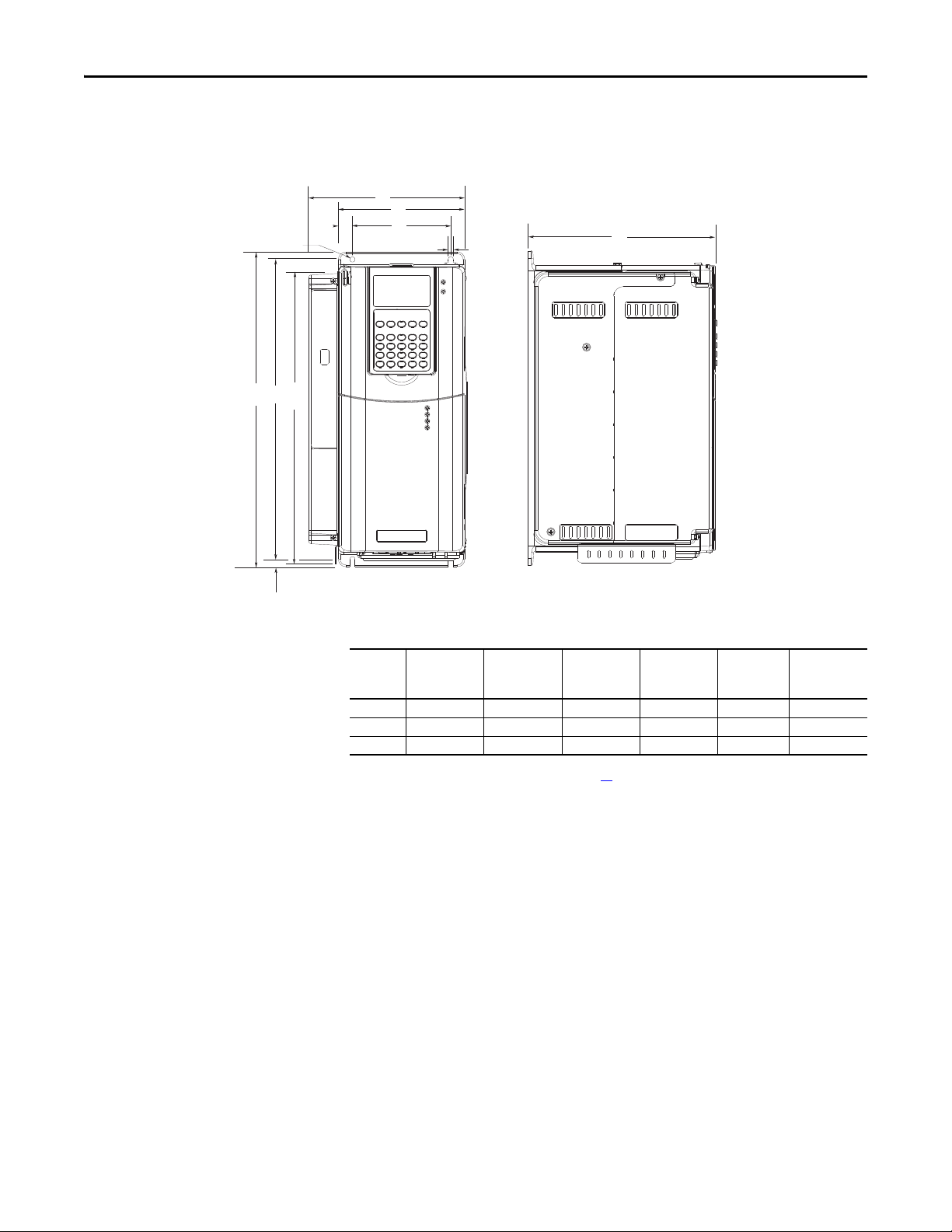
Dimensions are in millimeters and (inches)
Frame 1 Shown
15.0
(0.59)
5.8
(0.23) dia.
312
E
B
(12.28)
Approximate Dimensions
Figure 2 - Frames 1…3
AA
A
D
5.5 (0.22)
C
8.0
(0.31)
(1)
Frame
Slim CassetteAExpanded
BCDE
Cassette
AA
1 135.0 (5.31) 166.9 (6.57) 336.0 (13.23) 200.0 (7.87) 105.0 (4.13) 320.0 (12.60)
2 222.0 (8.74) 253.9 (9.99) 342.5 (13.48) 200.0 (7.87) 192.0 (7.56) 320.0 (12.60)
3 222.0 (8.74) 253.9 (9.99) 517.5 (20.37) 200.0 (7.87) 192.0 (7.56) 500.0 (19.69)
(1) Refer to Drive Rating to Frame Size Cross References on page 10 for frame information.
16 Rockwell Automation Publication 20D-IN024C-EN-P - July 2013

Figure 3 - Bottom Views, Frames 1…3
133.3
(5.25)
187.6
(7.39)
25.5
(1.00)
70.0 (2.76)
43.0 (1.69)
96.0 (3.78)
75.9 (2.99)
108.5 (4.27)
67.5 (2.66)
47.5 (1.87)
87.5 (3.44)
22.2 (0.87) Dia.
3 Places
28.6 (1.13) Dia.
185.1
(7.29)
162.3
(6.39)
66.0 (2.60)
94.7 (3.73)
105.3 (4.15)
97.0 (3.82)
137.2 (5.40)
187.0 (7.36)
22.7 (0.89)
29.0 (1.14)
127.7
(5.03)
151.1
(5.95)
160.1
(6.30)
165.1
(6.50)
184.5
(7.26)
22.2 (0.87) Dia.
28.7 (1.13) Dia.
2 Places
37.3 (1.47) Dia.
2 Places
66.0 (2.60)
94.7 (3.73)
105.3 (4.15)
130.0 (5.12)
186.0 (7.32)
22.7 (0.89)
29.0 (1.14)
127.7
(5.03)
160.1
(6.30)
165.1
(6.50)
184.5
(7.26)
28.7 (1.13) Dia.
2 Places
46.7 (1.84) Dia.
2 Places
34.9 (1.37) Dia.
2 Places
Vent Plate
Frame 1 Frame 2
Frame 3 - All Drives, except 50 Hp, 480V (37 kW, 400V) Frame 3 - 50 Hp, 480V (37 kW, 400V) Normal Duty
Dimensions are in millimeters and (inches)
22.4 (0.88) Dia.
2 Places
157.5
(6.20)
150.9
(5.94)
112.1
(4.41)
PowerFlex 700S Adjustable Frequency AC Drive - Phase II Control
167.5 (6.59)
39.3 (1.55)
57.2 (2.25)
72.7 (2.86)
156.9 (6.18)
106.0 (4.17)
139.4 (5.49)
177.4 (6.98)
28.7 (1.13) Dia.
3 Places
184.8
(7.28)
Rockwell Automation Publication 20D-IN024C-EN-P - July 2013 17
PowerFlex 700S Adjustable Frequency AC Drive - Phase II Control
54.1 (2.13) Dia.
2 Places
47.0 (1.85) Dia.
2 Places
28.7 (1.13) Dia.
2 Places
26.8 (1.06)
36.8 (1.45)
50.7 (2.00)
141.9
(5.59)
105.1
(4.14)
157.9
(6.21)
177.9
(7.00)
189.7
(7.47)
22.2 (0.87) Dia.
63.8 (2.51)
112.0 (4.41)
180.0 (7.09)
65.3 (2.57)
76.0 (2.99)
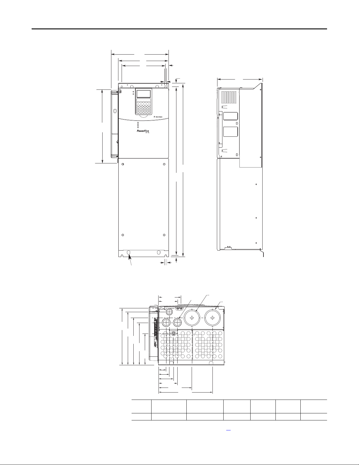
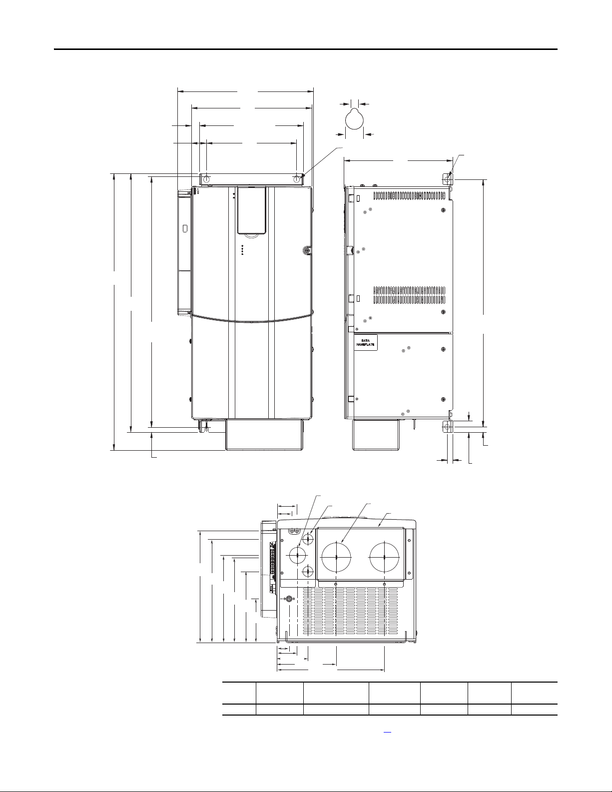
Dimensions are in millimeters and (inches)
Bottom View
Figure 4 - Frame 4
AA
A
D
13.0 (0.55)
312
(12.28)
7.0 (0.28) 2 Places
S
E
15.1 (0.59)
B
C
Lifting Holes
4 Places
7.0 (0.28)
3 Places
8.0
(0.31)
(1)
Frame
Slim Cassette
Expanded CassetteAABC (Max) DE
A (Max)
4 220.0 (8.66) 251.9 (9.92) 758.8 (29.87) 201.7 (7.94) 192.0 (7.56) 738.2 (29.06)
(1) Refer to Drive Rating to Frame Size Cross References on page 10 for frame information.
18 Rockwell Automation Publication 20D-IN024C-EN-P - July 2013
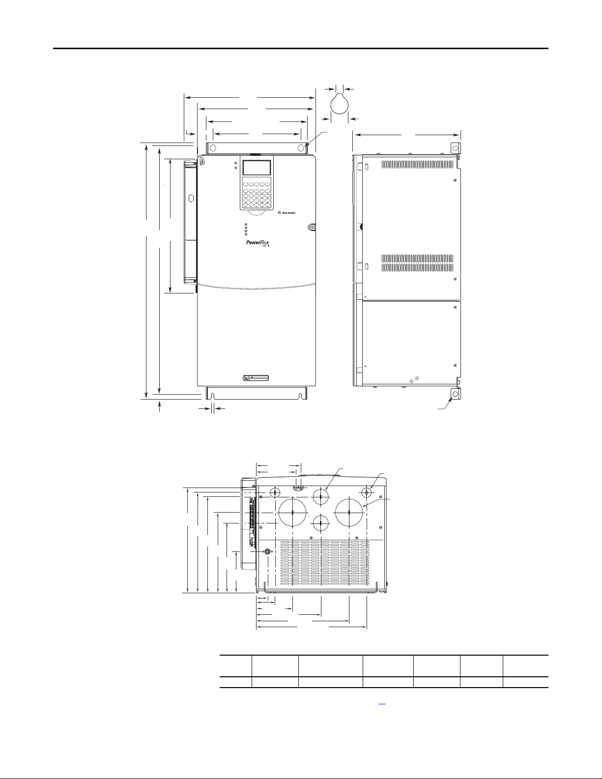
Figure 5 - Frame 5, 75 Hp, 480V (55kW, 400V)
Bottom View
HOT surfaces can cause severe burns
CAUTION
E
12.5
(0.49)
6.5 (0.26)
B
D
A
259.1 (10.20)
Detail
15.0 (0.59)
6.5 (0.26)
37.6
(1.48)
C
Lifting Holes - 4 Places
12.7 (0.50) Dia.
312
(12.28)
S
AA
96.0
(3.78)
159.5
(6.28)
184.0
(7.24)
220.0
(8.66)
229.5
(9.04)
241.9
(9.52)
45.0 (1.77)
85.0 (3.35)
93.2 (3.67)
104.0 (4.09)
150.0 (5.91)
215.0 (8.46)
255.0 (10.04)
28.0 (1.10)
22.2 (0.87) Dia.
2 Places
62.7 (2.47) Dia.
2 Places
34.9 (1.37) Dia.
2 Places
Dimensions are in millimeters and (inches)
PowerFlex 700S Adjustable Frequency AC Drive - Phase II Control
Frame
(1)
Slim Cassette
Expanded CassetteAABC (Max) DE
A (Max)
5 308.0 (12.2) 339.9 (13.4) 644.5 (25.4) 275.4 (10.9) 225.0 (8.9) 625.0 (24.6)
(1) Refer to Drive Rating to Frame Size Cross References on page 10 for frame information.
Rockwell Automation Publication 20D-IN024C-EN-P - July 2013 19
PowerFlex 700S Adjustable Frequency AC Drive - Phase II Control
Bottom View
Dimensions are in millimeters and (inches)
20.5 (0.8)
37.6 (1.48)
B
E
625.0
(24.6)
Figure 6 - Frame 5, 100 Hp, 480V (55kW, 400V)
AA
A
259.1 (10.20)
D
6.5 (0.3)
Detail
15.0 (0.6)
4 x Ø 12.7
C
(0.5)
617.0
(24.3)
12.0
(0.5)
241.9
(9.52)
223.5
(8.80)
188.5
(7.42)
184.3
(7.26)
Frame
42.6 (1.68)
31.9 (1.26)
153.5
(6.04)
96.0
(3.78)
28.0 (1.10)
44.0 (1.73)
(1)
Slim Cassette
13.0
(0.5)
66.4 (2.61)
128.0 (5.04)
34.9 (1.37) Dia.
232.3 (9.15)
22.2 (0.87) Dia.
2 Places
62.7 (2.47) Dia.
2 Places
Removable
Junction Box
Expanded CassetteAABC (Max) DE
27.6
(1.1)
A (Max)
5 308.9 (12.2) 340.8 (13.4) 689.6 (27.1) 270.35 (10.6) 225.0 (8.9) 644.5 (25.4)
(1) Refer to Drive Rating to Frame Size Cross References on page 10 for frame information.
13.0
(0.5)
20 Rockwell Automation Publication 20D-IN024C-EN-P - July 2013
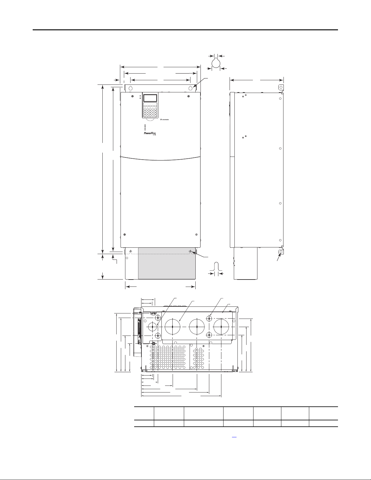
Figure 7 - Frame 6
Dimensions are in millimeters and (inches)
PowerFlex 700S Adjustable Frequency AC Drive - Phase II Control
8.5 (0.33)
49.6
(1.95)
B
A
360.6 (14.20)
D
Detail
18.0 (0.71)
C
E
126.3
(4.97)
13.5
(0.53)
242.0
(9.53)
222.3
(8.75)
Detail
Old Style Junction Box
Lifting Holes
4 Places
12.7 (0.50) Dia.
219.0
(8.62)
C (Max) DE
New Style Junction Box
56.2 (2.21)
45.6 (1.80)
148.5
(5.85)
116.6
(4.59)
47.1 (1.85)
52.1 (2.05)
69.1 (2.72)
Frame
130.1 (5.12)
(1)
Slim Cassette
230.1 (9.06)
280.1 (11.03)
(0.33)
34.9 (1.37) Dia.
3 Places
62.7 (2.47) Dia.
3 Places
330.1 (13.00)
Expanded CassetteAAB
8.5
22.2 (0.87) Dia.
4 Places
Removable Junction Box
151.8
(5.98)
(2)
185.4
(7.30)
A (Max)
6 403.9 (15.90) 435.8 (17.16) 850.0 (33.46) 275.5 (10.85) 300.0 (11.81) 825.0 (32.48)
(1) Refer to Drive Rating to Frame Size Cross References on page 10 for frame information.
(2) Junction Box can be removed if drive is mounted in a cabinet.
Rockwell Automation Publication 20D-IN024C-EN-P - July 2013 21
PowerFlex 700S Adjustable Frequency AC Drive - Phase II Control
Step 3: Lift and Mount the
Drive
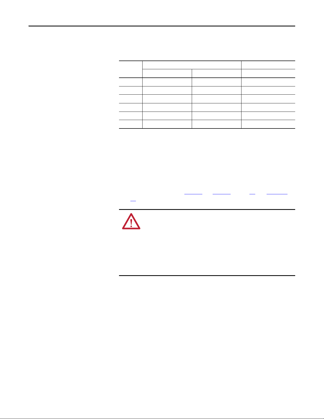
Drive Weights
Table 9 - Approximate Drive Weights
Frame Size Drive Rating Drive Weight
kW Hp kg (lb)
1 0.75…11 1…10 7.0 (15.5)
2 7.5…18.5 10…25 12.5 (27.6)
3 11…37 15…50 18.6 (40.9)
4 25…60 18.5…55 24.5 (54.0)
5 40…100 30…90 37.2 (82.0)
6 60…200 45…132 71.5 (157.5)
(1) Weights include HIM, DriveLogix controller with ControlNet daughtercard, Hi-Resolution Encoder Option, and 20-COMM-C
Contro lNet adapt er.
(2) Add an additional 3.6 kg (8.0 lb) for 200 Hp drives.
(1)
(2)
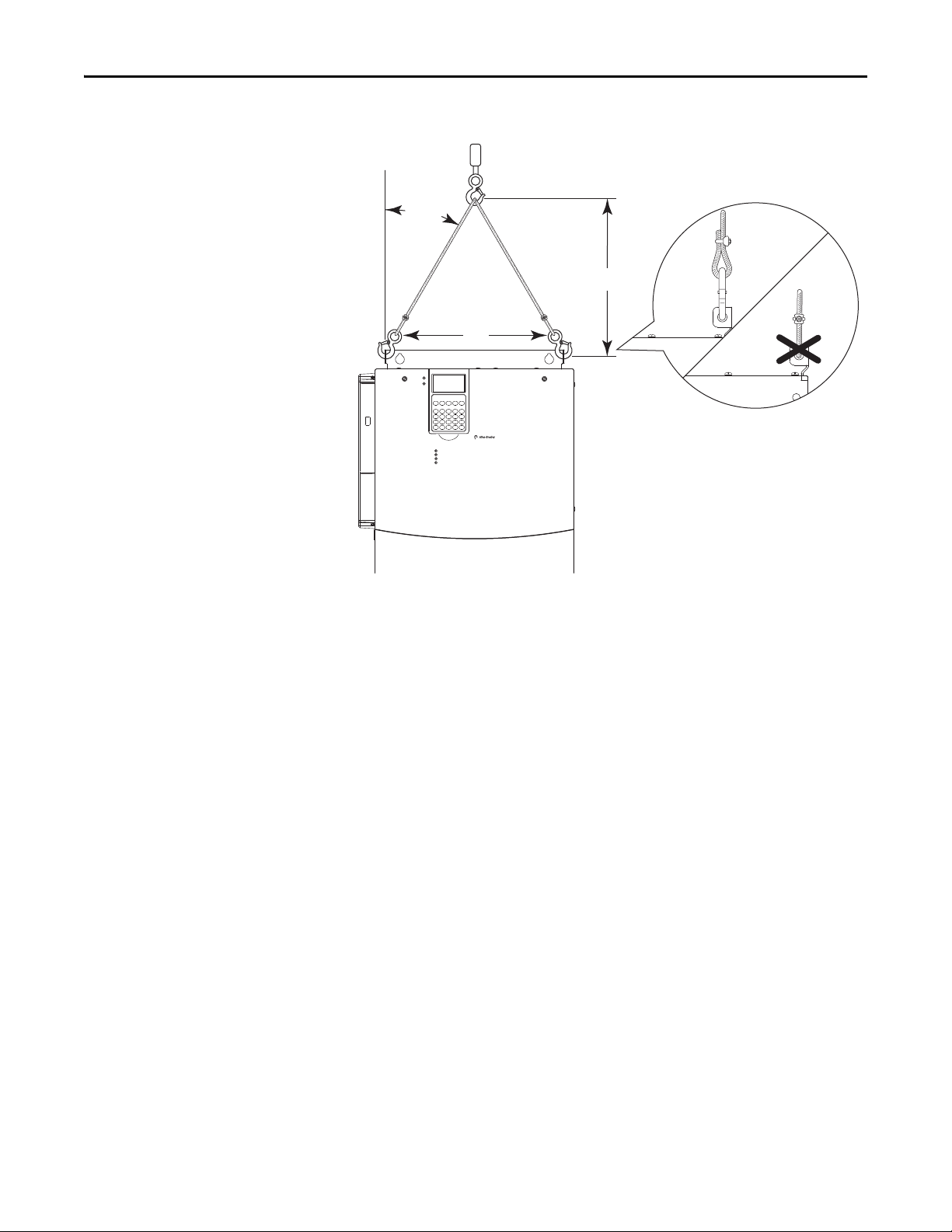
Attaching the Lifting Hardware
All lifting equipment and lifting components (hooks, bolts, lifts, slings, chains,
and so forth) must be properly sized and rated to safely lift and hold the weight of
the drive while mounting. See Figure 8
page 24
for lifting instructions.
and Figure 9 on page 23, and Figure 10 on
ATTENTION: To guard against possible personal injury and/or equipment
damage…
• Inspect all lifting hardware for proper attachment before lifting drive.
• Do not allow any part of the drive or lifting mechanism to make contact with
electrically charged conductors or components.
• Do not subject the drive to high rates of acceleration or deceleration while
transporting to the mounting location or when lifting.
• Do not allow personnel or their limbs directly underneath the drive when it is
being lifted and mounted.
22 Rockwell Automation Publication 20D-IN024C-EN-P - July 2013

Figure 8 - Lifting Frame 4 Drives
S
>
1
/
2 A
A
< 45°
S
>
1
/
2 A
A
< 45°
PowerFlex 700S Adjustable Frequency AC Drive - Phase II Control
Figure 9 - Lifting Frame 5 Drives
Rockwell Automation Publication 20D-IN024C-EN-P - July 2013 23
PowerFlex 700S Adjustable Frequency AC Drive - Phase II Control
>
1
/
2 A
A
< 45°
Figure 10 - Lifting Frame 6 Drives
24 Rockwell Automation Publication 20D-IN024C-EN-P - July 2013
 Loading...