


2100-ENET
Table of contents
 Loading...
CENTERLINE 2100 Motor Control Centers EtherNet/IP Network
Adapter
Catalog Numbers 2100-ENET Series A FRN 1.XXX
User Manual
Important User Information
Solid-state equipment has operational characteristics differing from those of electromechanical equipment. Safety
Guidelines for the Application, Installation and Maintenance of Solid State Controls (publication SGI-1.1
available from
your local Rockwell Automation sales office or online at http://www.rockwellautomation.com/literature/
) describes some
important differences between solid-state equipment and hard-wired electromechanical devices. Because of this difference,
and also because of the wide variety of uses for solid-state equipment, all persons responsible for applying this equipment
must satisfy themselves that each intended application of this equipment is acceptable.
In no event will Rockwell Automation, Inc. be responsible or liable for indirect or consequential damages resulting from the
use or application of this equipment.
The examples and diagrams in this manual are included solely for illustrative purposes. Because of the many variables and
requirements associated with any particular installation, Rockwell Automation, Inc. cannot assume responsibility or
liability for actual use based on the examples and diagrams.
No patent liability is assumed by Rockwell Automation, Inc. with respect to use of information, circuits, equipment, or
software described in this manual.
Reproduction of the contents of this manual, in whole or in part, without written permission of Rockwell Automation,
Inc., is prohibited.
Throughout this manual, when necessary, we use notes to make you aware of safety considerations.
Allen-Bradley, Rockwell Software, Rockwell Automation, E3 Plus, RSLogix, MicroLogix, ControlFLASH, Stratix 6000, RSLinx, CompactLogix, ControlLogix, DeviceLogix, Logix5000, PanelView, PLC-5, SLC,
TechConnect, CENTERLINE, Studio 5000, and IntelliCENTER are trademarks of Rockwell Automation, Inc.
Trademarks not belonging to Rockwell Automation are property of their respective companies.
WARNING: Identifies information about practices or circumstances that can cause an explosion in a hazardous environment,
which may lead to personal injury or death, property damage, or economic loss.
ATTENTION: Identifies information about practices or circumstances that can lead to personal injury or death, property
damage, or economic loss. Attentions help you identify a hazard, avoid a hazard, and recognize the consequence.
SHOCK HAZARD: Labels may be on or inside the equipment, for example, a drive or motor, to alert people that dangerous
voltage may be present.
BURN HAZARD: Labels may be on or inside the equipment, for example, a drive or motor, to alert people that surfaces may
reach dangerous temperatures.
IMPORTANT
Identifies information that is critical for successful application and understanding of the product.

Rockwell Automation Publication 2100-UM006A-EN-P - July 2013 3
Table of Contents
Preface
Additional Resources . . . . . . . . . . . . . . . . . . . . . . . . . . . . . . . . . . . . . . . . . . . . . . . 5
Rockwell Automation Support . . . . . . . . . . . . . . . . . . . . . . . . . . . . . . . . . . . . . . 6
Local Product Support. . . . . . . . . . . . . . . . . . . . . . . . . . . . . . . . . . . . . . . . . . 6
Technical Product Assistance. . . . . . . . . . . . . . . . . . . . . . . . . . . . . . . . . . . . 6
Conventions Used in This Manual . . . . . . . . . . . . . . . . . . . . . . . . . . . . . . . . . . 6
Studio 5000 Environment . . . . . . . . . . . . . . . . . . . . . . . . . . . . . . . . . . . . . . . . . . 7
Chapter 1
Getting Started
Adapter Components . . . . . . . . . . . . . . . . . . . . . . . . . . . . . . . . . . . . . . . . . . . . . . 9
Features . . . . . . . . . . . . . . . . . . . . . . . . . . . . . . . . . . . . . . . . . . . . . . . . . . . . . . . . . . . 9
Compatible Products. . . . . . . . . . . . . . . . . . . . . . . . . . . . . . . . . . . . . . . . . . . . . 10
Required Equipment . . . . . . . . . . . . . . . . . . . . . . . . . . . . . . . . . . . . . . . . . . . . . 10
Equipment Shipped with the Adapter. . . . . . . . . . . . . . . . . . . . . . . . . . 10
User-supplied Equipment . . . . . . . . . . . . . . . . . . . . . . . . . . . . . . . . . . . . . 10
Safety Precautions. . . . . . . . . . . . . . . . . . . . . . . . . . . . . . . . . . . . . . . . . . . . . . . . 11
Quick Start . . . . . . . . . . . . . . . . . . . . . . . . . . . . . . . . . . . . . . . . . . . . . . . . . . . . . . 12
Chapter 2
Install the Adapter
Prepare for an Installation . . . . . . . . . . . . . . . . . . . . . . . . . . . . . . . . . . . . . . . . 13
Connect the Adapter to the End Device. . . . . . . . . . . . . . . . . . . . . . . . . . . . 14
Connect the Adapter to the Network . . . . . . . . . . . . . . . . . . . . . . . . . . . . . . 15
Apply Power. . . . . . . . . . . . . . . . . . . . . . . . . . . . . . . . . . . . . . . . . . . . . . . . . . . . . 15
Start-up Status Indications . . . . . . . . . . . . . . . . . . . . . . . . . . . . . . . . . . . . 15
Commission the Adapter . . . . . . . . . . . . . . . . . . . . . . . . . . . . . . . . . . . . . . . . . 16
Chapter 3
Configure the Adapter
Configuration Tools . . . . . . . . . . . . . . . . . . . . . . . . . . . . . . . . . . . . . . . . . . . . . 17
Using BOOTP . . . . . . . . . . . . . . . . . . . . . . . . . . . . . . . . . . . . . . . . . . . . . . . . . . 17
Configure the Adapter by Using the BOOTP Server . . . . . . . . . . . . 18
Change an Assigned IP Address or Enable BOOTP in the
2100-ENET Adapter . . . . . . . . . . . . . . . . . . . . . . . . . . . . . . . . . . . . . . . . . 21
Set the Data Rate. . . . . . . . . . . . . . . . . . . . . . . . . . . . . . . . . . . . . . . . . . . . . . . . . 22
Set the I/O Configuration . . . . . . . . . . . . . . . . . . . . . . . . . . . . . . . . . . . . . . . . 22
Set a Fault Action . . . . . . . . . . . . . . . . . . . . . . . . . . . . . . . . . . . . . . . . . . . . . . . . 23
Reset the Adapter . . . . . . . . . . . . . . . . . . . . . . . . . . . . . . . . . . . . . . . . . . . . . . . . 24
Update the Adapter . . . . . . . . . . . . . . . . . . . . . . . . . . . . . . . . . . . . . . . . . . . . . . 24
Update the E3 Plus or 825-P . . . . . . . . . . . . . . . . . . . . . . . . . . . . . . . . . . 24
Chapter 4
Configure the I/O
Use RSLinx Classic Software . . . . . . . . . . . . . . . . . . . . . . . . . . . . . . . . . . . . . . 25
ControlLogix Example . . . . . . . . . . . . . . . . . . . . . . . . . . . . . . . . . . . . . . . . . . . 26
Add the Bridge to the I/O Configuration. . . . . . . . . . . . . . . . . . . . . . . 27
Using RSLogix 5000 End Device Add-on Profiles (version 16
or later). . . . . . . . . . . . . . . . . . . . . . . . . . . . . . . . . . . . . . . . . . . . . . . . . . . . . . 30

4 Rockwell Automation Publication 2100-UM006A-EN-P - July 2013
Table of Contents
Using the RSLogix 5000 Generic Profile (all versions) . . . . . . . . . . . 35
Logix Controller I/O Messaging . . . . . . . . . . . . . . . . . . . . . . . . . . . . . . . 35
Limitations When Using PLC-5, SLC 500, or MicroLogix 1100 or
MicroLogix 1400 Controllers . . . . . . . . . . . . . . . . . . . . . . . . . . . . . . . . . . . . . 39
Chapter 5
Using the I/O
About I/O Messaging. . . . . . . . . . . . . . . . . . . . . . . . . . . . . . . . . . . . . . . . . . . . . 41
Understanding the I/O Image . . . . . . . . . . . . . . . . . . . . . . . . . . . . . . . . . . . . . 41
ControlLogix Controller Image. . . . . . . . . . . . . . . . . . . . . . . . . . . . . . . . 42
ControlLogix Example. . . . . . . . . . . . . . . . . . . . . . . . . . . . . . . . . . . . . . . . . . . . 44
Create Ladder Logic by Using the RSLogix 5000 E3 Plus Module
Add-E3 Plus on Profiles (version 16 or later) . . . . . . . . . . . . . . . . . . . . 44
Create Ladder Logic by Using the RSLogix 5000 Classic Profile
(versions 13…15) . . . . . . . . . . . . . . . . . . . . . . . . . . . . . . . . . . . . . . . . . . . . . 45
Create Ladder Logic by Using the RSLogix 5000 Generic Profile
(all versions). . . . . . . . . . . . . . . . . . . . . . . . . . . . . . . . . . . . . . . . . . . . . . . . . . 46
Chapter 6
Using Explicit Messaging
About Explicit Messaging . . . . . . . . . . . . . . . . . . . . . . . . . . . . . . . . . . . . . . . . . 47
Performing Explicit Messages . . . . . . . . . . . . . . . . . . . . . . . . . . . . . . . . . . . . . 48
ControlLogix Examples . . . . . . . . . . . . . . . . . . . . . . . . . . . . . . . . . . . . . . . . . . . 48
Explicit Messaging by Using RSLogix 5000 Software (version 15
or later) . . . . . . . . . . . . . . . . . . . . . . . . . . . . . . . . . . . . . . . . . . . . . . . . . . . . . . 49
Chapter 7
Troubleshooting
Understanding the Status Indicators . . . . . . . . . . . . . . . . . . . . . . . . . . . . . . . 57
PORT Status Indicator . . . . . . . . . . . . . . . . . . . . . . . . . . . . . . . . . . . . . . . . . . . 58
MOD Status Indicator. . . . . . . . . . . . . . . . . . . . . . . . . . . . . . . . . . . . . . . . . . . . 58
NET A Status Indicator. . . . . . . . . . . . . . . . . . . . . . . . . . . . . . . . . . . . . . . . . . . 59
NET B Status Indicator. . . . . . . . . . . . . . . . . . . . . . . . . . . . . . . . . . . . . . . . . . . 59
Appendix A
Specifications
Communication . . . . . . . . . . . . . . . . . . . . . . . . . . . . . . . . . . . . . . . . . . . . . . . . . 61
Electrical . . . . . . . . . . . . . . . . . . . . . . . . . . . . . . . . . . . . . . . . . . . . . . . . . . . . . . . . 62
Mechanical . . . . . . . . . . . . . . . . . . . . . . . . . . . . . . . . . . . . . . . . . . . . . . . . . . . . . . 62
Environmental . . . . . . . . . . . . . . . . . . . . . . . . . . . . . . . . . . . . . . . . . . . . . . . . . . . 62
Regulatory Compliance . . . . . . . . . . . . . . . . . . . . . . . . . . . . . . . . . . . . . . . . . . . 62
Glossary
Index

Rockwell Automation Publication 2100-UM006A-EN-P - July 2013 5
Preface
Additional Resources
These documents contain additional information concerning related products
from Rockwell Automation.
You can view or download publications at
http:/www.rockwellautomation.com/literature/
. To order paper copies of
technical documentation, contact your local Allen-Bradley distributor or
Rockwell Automation sales representative. For information such as firmware
updates or answers to product-related questions, go to the Support website at
http://www.rockwellautomation.com/rockwellautomation/support
.
Top ic Pag e
Additional Resources 5
Rockwell Automation Support 6
Conventions Used in This Manual 6
Studio 5000 Environment 7
Resource Description
http://www.odva.org
Accesses the Open DeviceNet Vendors Association
(ODVA) w ebsite.
EtherNet/IP Media Planning and Installation Manual
(1)
,
publication ODVA Pub. 148
(1) Use this link to the ODVA EtherNet/IP library for these publications: http://odva.org/Home/ODVATECHNOLOGIES/EtherNetIP/
EtherNetIPLibrary/tabid/76/Default.aspx.
Provides general guidelines for planning and installing
an EtherNet/IP Media.
EtherNet/IP Network Infrastructure Guidelines
(1)
, publication
ODVA Pub. 35
Provides general guidelines for the network
infrastructure for an EtherNet/IP Media.
Ethernet Design Considerations Reference Manual,
publication ENET-RM002
Provides general guidelines for the performance
application solution for an EtherNet/IP Media.
Getting Results with RSLinx® Guide, and online help,
publication LINX-GR001
Provides general guidelines for installing and navigating
the RSLinx Classic soft ware.
RSLogix™ 5 Getting Results Guide, and online help,
publication LG5-GR002
Provides general guidelines for installing and navigating
the RSLogic 5 software.
RSLogix 500 Getting Results Guide, and online help,
publication LG500-GR002
Provides general guidelines for installing and navigating
the RSLogic 500 software.
RSLogix 5000 Getting Results Guide, publication
LG500-GR002
Provides general guidelines for installing and navigating
the RSLogic 5000 software.
EtherNet/IP Modules in Logix5000 Control Systems User
Manual, publication ENET-UM001
Provides general guidelines for using EtherNet/IP
communication modules with a Logix5000™ controller.
Enhanced and Ethernet PLC-5 Programmable Controllers User
Manual, publication 1785-UM012
Provides general guidelines for designing, operating,
and maintaining an Enhanced and Ethernet PLC-5®
programmable controller system.
SLC 500 Modular Hardware Style User Manual, publication
1747-UM011
Provides general guidelines for designing, installing,
programming, or troubleshooting control systems with
a SLC™ 500 programmable controller.
MicroLogix™ 1100 Programmable Controllers User Manual,
publication 1763-UM001
Provides general guidelines for designing, installing,
programming, or troubleshooting control systems that
use MicroLogix 1100 controllers.
MicroLogix 1400 Programmable Controllers User Manual,
publication 1766-UM001
Provides general guidelines for designing, installing,
programming, or troubleshooting control systems that
use MicroLogix 1400 controllers.
IntelliCENTER® Technology with EtherNet, publication
2100-TD031
Describes cable system construction and components
associated with an EtherNet/IP network.
Industrial Automation Wiring and Grounding Guidelines,
publication 1770-4.1
Provides general guidelines for installing a Rockwell
Automation® industrial system.
Product Certifications website, http://www.ab.com
Provides declarations of conformity, certificates, and
other certification details.

6 Rockwell Automation Publication 2100-UM006A-EN-P - July 2013
Preface
Rockwell Automation
Support
Rockwell Automation, Inc. offers support services worldwide, with over 75 sales/
support offices, over 500 authorized distributors, and over 250 authorized
systems integrators located through the United States alone. In addition,
Rockwell Automation, Inc. representatives are in every major country in the
world.
Local Product Support
Contact your local Rockwell Automation, Inc. representative for the following:
• Sales and order support
• Product technical training
• Wa rra nt y su pp or t
• Support service agreements
Technical Product Assistance
For technical assistance, review the information in Chapter 7 first. If you still have
problems, then access the Rockwell Automation Technical Support website at
https://rockwellautomation.custhelp.com
or contact Rockwell Automation, Inc.
Conventions Used in This
Manual
This manual provides information about the adapter and using it with an
E3/E3 Plus™ Solid State Overload (firmware revision 5.xx or later) or 825-P
Modular Protection System (firmware revision 65.xx or later). Other firmware
revisions are not fully compatible with the 2100-ENET adapter and must be
upgraded to a supported revision of firmware (See Update the E3 Plus or 825-P
on page 24). The adapter cannot be used with other devices. If another
DeviceNet native device is connected to the 2100-ENET adapter, an I/O
connection is not supported through the 2100-ENET adapter.
The following conventions are used throughout this manual:
• The E3/E3 Plus Solid State Overload is referred to as ‘E3 Plus’ throughout
this manual. The 825-P Modular Protection System is referred to as
‘825-P’. When being referred to together, ‘end device’ is used.
• Parameter names are shown in the format Parameter xx - [*]. The xx
represents the parameter number. The * represents the parameter name—
for example Parameter 01 - [L1 Current].
• The firmware release is displayed as FRN X.xxx. The ‘FRN’ signifies
Firmware Release Number. The ‘X’ is the major release number. The ‘xxx’
is the minor update number.
Rockwell Automation Publication 2100-UM006A-EN-P - July 2013 7
Preface
• Screen shots in this manual were taken from the following software
packages. Your screen can appear slightly different if your version of the
software is not the same:
• RSLinx software, version 2.51
• RSLogix 5 software, version 7.20
• RSLogix 500 software, version 7.20
• RSLogix 5000 software, version 19
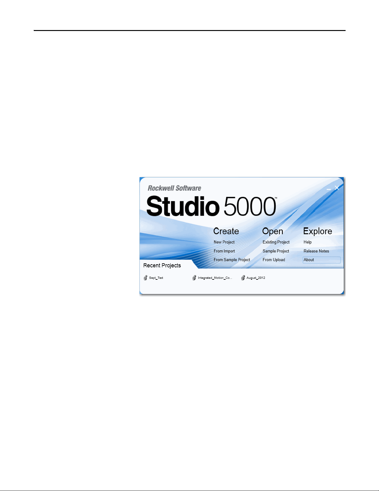
Studio 5000 Environment
The Studio 5000™ Engineering and Design Environment combines engineering
and design elements into a common environment. The first element in the Studio
5000 environment is the Logix Designer application. The Logix Designer
application is the rebranding of RSLogix 5000 software and will continue to be
the product to program Logix5000 controllers for discrete, process, batch,
motion, safety, and drive-based solutions.
The Studio 5000 environment is the foundation for the future of Rockwell
Automation® engineering design tools and capabilities. This environment is the
one place for design engineers to develop all of the elements of their control
system.

8 Rockwell Automation Publication 2100-UM006A-EN-P - July 2013
Preface
Notes:
Rockwell Automation Publication 2100-UM006A-EN-P - July 2013 9
Chapter 1
Getting Started
The adapter is for use only with the E3 Plus (firmware revision 5.xx or later) or
825-P (firmware revision 65.xx or later). Other firmware revisions are not fully
compatible and must be updated to a compatible firmware revision (see Upda te
the E3 Plus or 825-P on page 24).
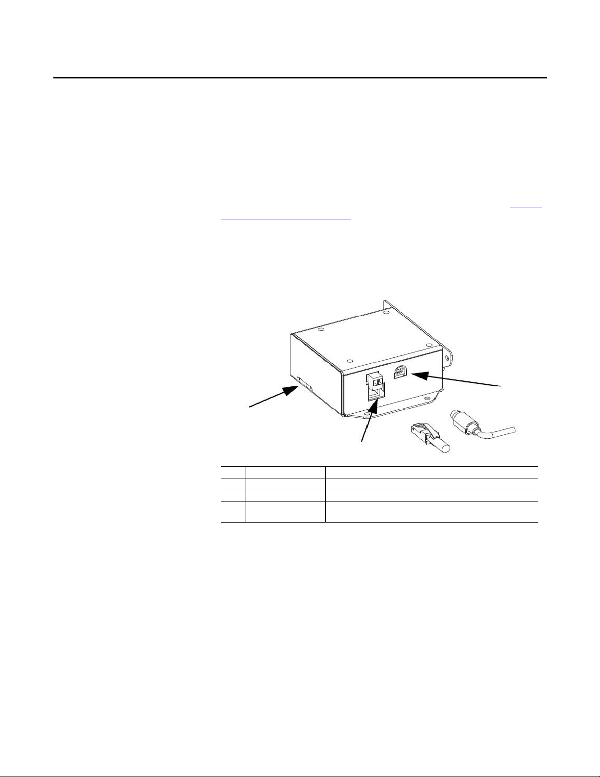
Adapter Components
The adapter has these components.
Figure 1: Components of the Adapter
The E3 Plus and 825-P must be set to node 63 and have a communication rate of
500 Kpbs (or have the autobaud enabled). This is the default state of each of
these devices.
Features
The features of the adapter include the following :
• Can be panel-mounted or DIN Rail Mounted with PN-107433 available
through your Allen-Bradley distributor. The adapter can be mounted with
either two or four screws in any orientation necessary.
• Grounding is provided through the housing. Grounding is to be provided
by one of the panel mounting holes.
Item Part Description
1 Status Indicators Four status indicators for the DeviceNet, adapter, and network connection.
2 E3 Connector This connector is provided for the connection to the E3 Plus or the 825-P.
3 Ethernet Connector An RJ-45 connector for the Ethernet cable. The connector is CAT-5 compliant to
be sure of reliable data transfer on 100Base-TX Ethernet connections.
1
2
3

10 Rockwell Automation Publication 2100-UM006A-EN-P - July 2013
Chapter 1 Getting Started
• Compatibility with IntelliCENTER software for parameter configuration
of the end device. A Bootstrap Protocol (BOOTP) server can be used to
configure the network address for the adapter.
• Status indicators that report the status of the end device communication,
the adapter, and network.
• Explicit Messaging support to the connected device.
Compatible Products
At the time of publication, compatible products include the following:
• E3/E3 Plus Overload Relays
• 825-P Modular Protection System
Required Equipment
This section lists the equipment shipped with the adapter and what supplies you
need.
Equipment Shipped with the Adapter
When you unpack the adapter, verify that the package includes the following:
• (1) 2100-ENET Adapter
• (1) 0.3 m 2100-ENET adapter to DeviceNet Cable to connect the end
device to the adapter
User-supplied Equipment
To install and configure the adapter, you must supply the following:
• A small flathead screwdriver
• Ethernet cable - refer to the EtherNet/IP Network Infrastructure
Guidelines, publication ODVA, Pub. 35
• Ethernet switch – refer to the Ethernet Design Considerations Reference
Manual, publication ENET-RM002
• Configuration tool, such as the following:
– IntelliCENTER software, version 3.00.01 or later
– BOOTP Server, version 2.1 or later (network setup only)
• Controller configuration software (such as RSLogix 5 or RSLogix 500
software or the Studio 5000 environment)
• A personal computer connection to the EtherNet/IP network
Rockwell Automation Publication 2100-UM006A-EN-P - July 2013 11
Getting Started Chapter 1
Safety Precautions
Read the following safety precautions carefully.
ATTENTION: Risk of injury or equipment damage exists. If the adapter is
transmitting control I/O to the end device, the end device can fault when you
reset the adapter. Determine how your end device responds before resetting an
adapter.
ATTENTION: Risk of injury or equipment damage exists. Various parameters in
the end device let you determine the action of the adapter and connected end
device if I/O communication is disrupted or the controller is idle. By default,
these parameters turn off the outputs of the connected E3 Plus and 825-P. You
can set these parameters so that outputs react as desired (for example, to keep
the motor running). Take precautions to be sure that the settings of these
parameters do not create a risk of injury or equipment damage. When
commissioning the end device, verify that your system responds correctly to
various situations (for example, a disconnected cable or a faulted controller).
ATTENTION: Risk of injury or equipment damage exists. When a system is
configured for the first time, there can be unintended or incorrect machine
motion. Disconnect the motor from the machine or process during initial system
testing.
ATTENTION: Risk of injury or equipment damage exists. The examples in this
publication are intended solely for purposes of example. There are many
variables and requirements with any application. Rockwell Automation, Inc.
does not assume responsibility or liability (to include intellectual property
liability) for actual use of the examples shown in this publication.

12 Rockwell Automation Publication 2100-UM006A-EN-P - July 2013
Chapter 1 Getting Started
Quick Start
This section is provided to help experienced users quickly start using the adapter.
If you are unsure how to complete a step, refer to the referenced chapter.
Step Action Refer to
1 Review the safety precautions for the adapter. Throughout This Manual
2 Verify that the end device is properly installed. End Device User Manual
3 Install the adapter.
Verify that the end device is not powered. Then, connect the adapter to the
network by using an Ethernet cable. Connect the end device by using the
2100-ENET to DeviceNet cable. Use the panel mounting holes to secure and
ground the adapter to the mounting surface. The DIN Rail adapter can also be
used to mount the adapter.
When installing the adapter by using the DIN Rail adapter, the following parts
are needed:
(1) PN-107443: DIN Rail Adapter
(2) 419062-3PEF: M3 x 0.5 flat head screw
Chapter 2, Install the Adapter
4 Apply power to the adapter.
The adapter requires 24V DC to operate. This connection also supplies 24V DC to
the end device for the powerup and DeviceNet communication to the
2100-ENET adapter.
Chapter 2, Install the Adapter
5 Configure the adapter.
Set the IP Address, subnet mask, and gateway address for the adapter.
Important: These are the only parameters that need to be configured in the
adapter because all of the other configuration lies with the end device.
Configure the end device parameters as required by your application.
Important: The node address must be 63 and the data rate must be either
500 Kpbs or set to autobaud in the end device.
E3 Plus or 825-P User Manual
and Chapter 3, Conf igure the
Adapter
6 Configure the controller to communicate with the adapter.
Use a controller configuration tool, such as RSLogix software, to configure the
master on the EtherNet/IP network to recognize the adapter and end device.
Chapter 4, Configure the I/O
7 Create a ladder logic program.
Use a controller configuration tool, such as RSLogix software, to create a ladder
logic program that enables you to do the following:
• Control the adapter and connected drive by using I/O.
• Monitor or configure the end device by using Explicit messages.
Chapter 5, Using the I/O
Chapter 6, Using Explicit
Messaging

Rockwell Automation Publication 2100-UM006A-EN-P - July 2013 13
Chapter 2
Install the Adapter
This chapter provides instructions for installing the adapter.
Prepare for an Installation
Before installing the adapter, refer to these guidelines:
• Make sure the Ethernet switch is the correct type. A managed switch that
supports Internet Group Management Protocol (IGMP) snooping is
usually recommended. An unmanaged switch can be used instead if
RSLogix 5000 software, version 18 or later, is used and all devices on the
network are configured for unicast I/O. For more details, see the following
documents:
– EtherNet/IP Media Planning and Installation Manual, ODVA
publication 148
– EtherNet/IP Network Infrastructure Guidelines, ODVA publication
35
– Ethernet Design Considerations Reference Manual, Rockwell
Automation publication ENET-RM002
• Understand IGMP Snooping/Ethernet Switches
The 2100-ENET adapter is a multicast device. In most situations, an
IGMP snooping (managed) switch is required. If more than one
2100-ENET adapters are connected to the switch, a managed switch is
required—otherwise the end device can fault on a communication
(comms) loss. The 2100-ENET adapter, RSLogix 5000 software,
version 18 or later, and a ControlLogix® or CompactLogix™ controller
supports unicast. When all Ethernet connections are set up as unicast
devices in RSLogix 5000 software, then an IGMP snooping (managed)
switch is not needed.
Much of EtherNet/IP network implicit (I/O) messaging uses IP
multicast to distribute I/O control data, which is consistent with the
CIP producer/consumer model. Historically, most switches have
treated multicast packets the same as broadcast packets. That is, all
multicast packets are re-transmitted to all ports.
Top ic Pag e
Prepare for an Installation 13
Connect the Adapter to the End D evice 14
Connect the Adapter to the Network 15
Apply Power 15
Commission the Adapter 16

14 Rockwell Automation Publication 2100-UM006A-EN-P - July 2013
Chapter 2 Install the Adapter
IGMP snooping constrains the flooding of multicast traffic by
dynamically configuring switch ports so that multicast traffic is
forwarded only to ports associated with a particular IP multicast group.
Switches that support IGMP snooping (managed switches) learn which
ports have devices that are part of a particular multicast group and
forward only the multicast packets to the ports that are part of the
multicast group.
Be careful as to what level of support a switch has of IGMP snooping.
Some layer 2 switches that support IGMP snooping require a router,
which could be a layer 3 switch, to send out IGMP polls to learn what
devices are part of the multicast group. Some layer 2 switches can use
IGMP snooping without a router sending polls. If your control system
is a stand-alone network or is required to continue performing if the
router is out of service, make sure the switch you are using supports
IGMP snooping without a router being present:
• Refer to Appendix
A for the number of CIP connections supported
by the 2100-ENET adapter.
• Verify that you have all required equipment. Refer to Required
Equipment on page 10.
Connect the Adapter to the
End Device
1. Connect the circular connector end of the 2100-ENET
adapter-to-DeviceNet cable to the PORT connector on the bottom of the
2100-ENET.
2. Connect the DeviceNet connector end of the 2100-ENET
adapter-to-DeviceNet cable to the end device.
3. Configure the end device’s DeviceNet address to node 63 by following the
instructions provided in the appropriate end device user manual.
4. Configure the end device’s DeviceNet data rate to 500 Kpbs following the
instructions provided in the appropriate end device User Manual.
Rockwell Automation Publication 2100-UM006A-EN-P - July 2013 15
Install the Ad apter Chapter 2
Connect the Adapter to the
Network
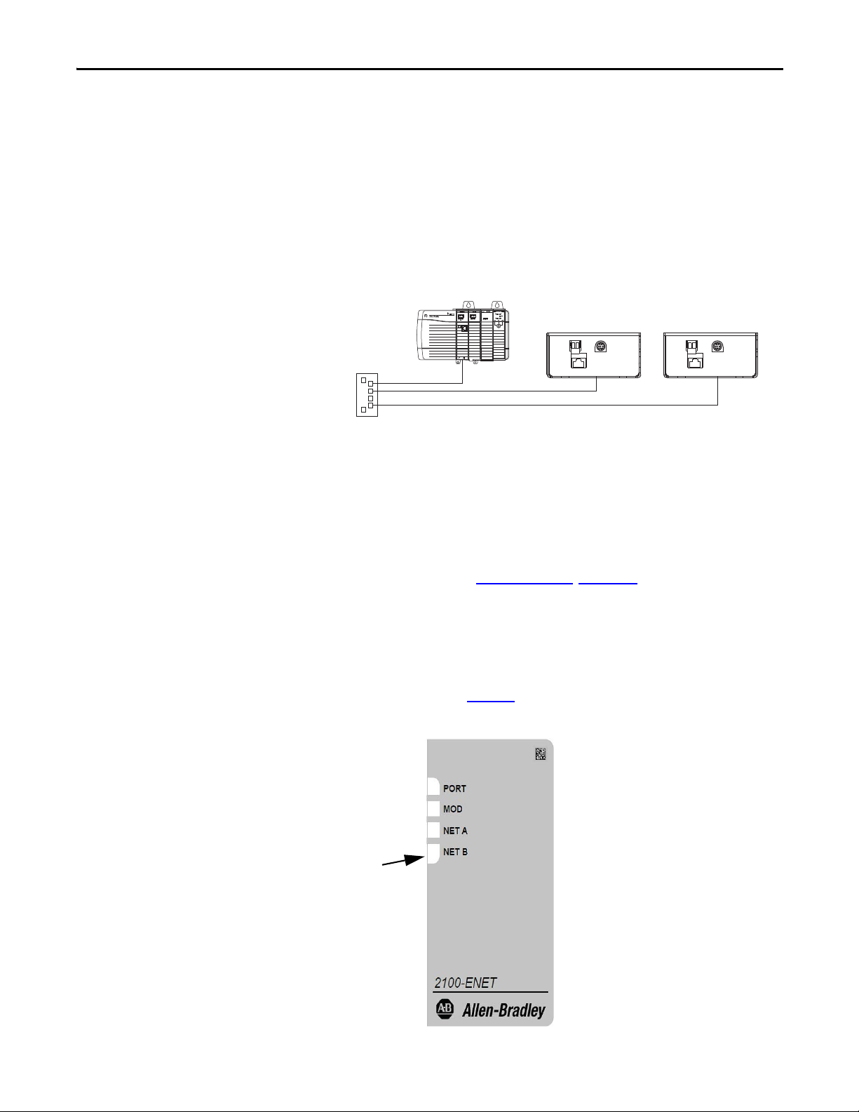
Follow these steps to connect the adapter to the network.
1. Connect one end of an Ethernet cable to the network.
See following graphic for an example of wiring to an EtherNet/IP
network.
Connecting the Ethernet Cable to the Network
2. Route the other end of the Ethernet cable to the EtherNet/IP network
connector on the bottom of the 2100-ENET adapter.
Apply Power
Connect 24V power to the DC+ connector on the bottom of the 2100-ENET
adapter. When power is supplied to the adapter for the first time, its topmost
status indicator is steady green or flashing green after an initialization. If it is red,
there is a problem. Refer to Troubleshooting
, Chapter 7.
Start-up Status Indications
After power has been applied, the status indicators can be viewed on the front of
the 2100-ENET adapter (Figure 2
).
Figure 2: 2100-ENET Adapter
Ethernet
Switch
Control ler
(ControlLogix show n with
1756-ENBT bridge)
2100-ENET Adapter
Status Indicator s

16 Rockwell Automation Publication 2100-UM006A-EN-P - July 2013
Chapter 2 Install the Adapter
After installing the adapter and applying power, refer to Tab le 8 on p ag e 58 for a
description of the status indicators.
Commission the Adapter
To commission the adapter, you must set a unique IP address on the network.
(Refer to the Glossary
for details about IP addresses.) After installing the adapter
and applying power, you can set the IP address by using a BOOTP server or by
setting adapter parameters. See Chapter 3
for details.
By default, the adapter is configured so that you must set the IP address by using a
BOOTP server. To set the IP address by using adapter parameters, you must
disable the BOOTP feature. See Using BOOTP
on page 17 for details.

Rockwell Automation Publication 2100-UM006A-EN-P - July 2013 17
Chapter 3
Configure the Adapter
This chapter provides instructions and information for setting up the adapter.
For a list of E3 Plus or 825-P parameters, refer to the appropriate user manual.
For definitions of terms in this chapter, refer to the Glossary
.
Configuration Tools
The adapter does not have any parameters that need to be configured. The only
items that need to be configured are the IP Address, Subnet Mask and Gateway
Address. This can be done only with a BOOTP Server.
Using BOOTP
By default, the adapter is configured so that you can set its IP address, subnet
mask, and gateway address by using a BOOTP utility. You can select from a
variety of BOOTP utilities. These instructions use the Rockwell Automation
BOOTP Server, version 2.3 or later, a free standalone program that incorporates
the functionality of standard BOOTP utilities with a graphical interface. It is
available from http://www.software.rockwell.com/support/download/
detail.cfm?ID=3390. Refer to the Read Me file and online Help for directions
and more information.
Top ic Pag e
Configuration Tools 17
Using BOOTP 17
Set the Data Rate 22
Set the I/O Configuration 22
Set a Fault Action 23
Reset the Adapter 24
Update the Adapter 24
TIP
Many switches and routers support BOOTP as well and can configure this
information automatically. The Stratix 6000™ switch is an example of a
switch that supports BOOTP.
18 Rockwell Automation Publication 2100-UM006A-EN-P - July 2013
Chapter 3 Configure the Adapter
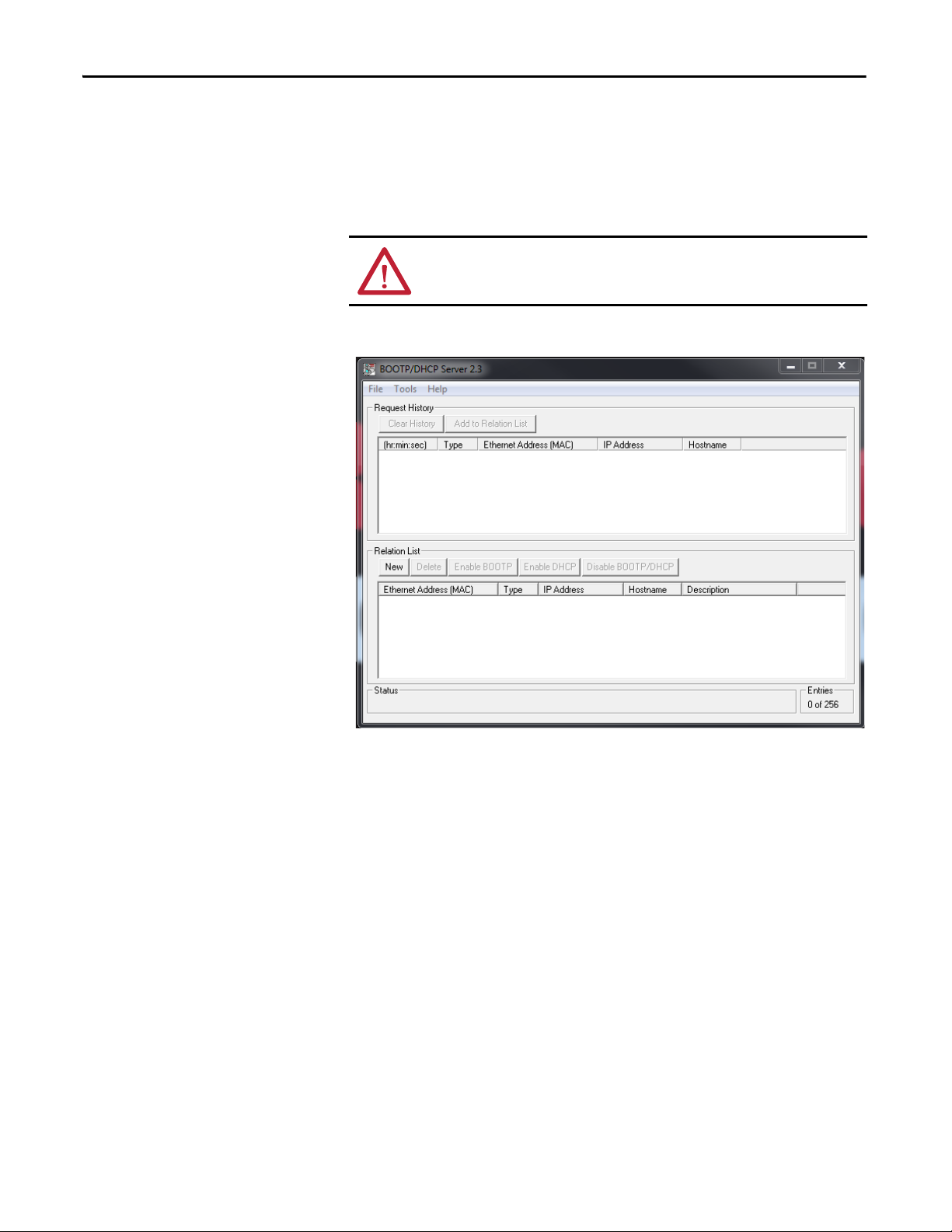
Configure the Adapter by Using the BOOTP Server
Connect your personal computer to the network the 2100-ENET adapter is
connected. It can be connected directly to your personal computer, if a network
does not exist.
1. Start your BOOTP program.
ATTENTION: Do not apply power to the 2100-ENET adapter until directed to do
so.
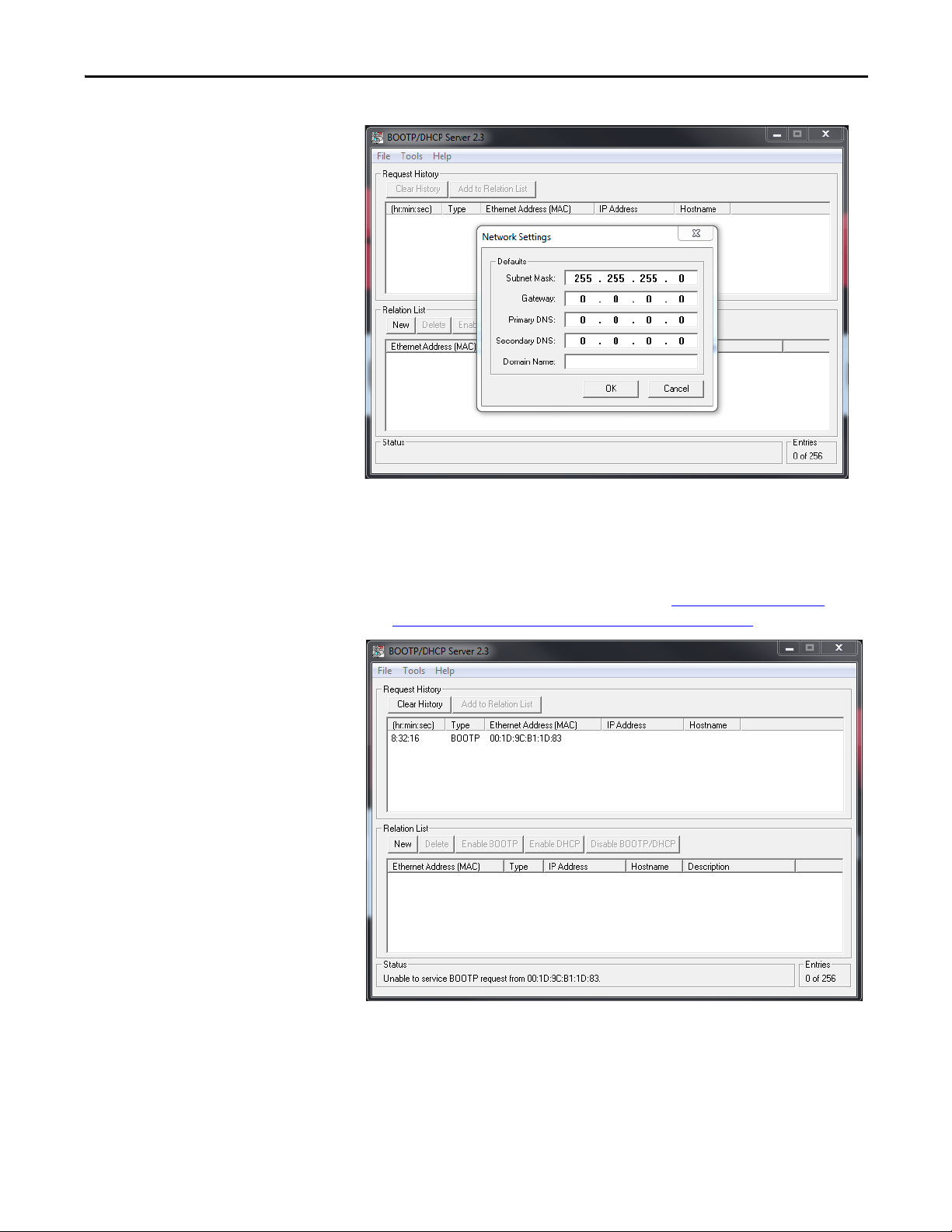
TIP
From the Tools menu, choose Network Settings. Verify that the Subnet Mask
and the Gateway Address match those of your network. If necessary, change
the values to match your network.
Rockwell Automation Publication 2100-UM006A-EN-P - July 2013 19
Configure the Adapter Chapter 3
2. Click OK.
3. Apply power to the non-configured 2100-ENET adapter.
The adapter immediately begins broadcasting its BOOTP message which
indicates it is available to have its address set. If the adapter does not
broadcast its BOOTP message, refer to the Change an Assigned IP
Address or Enable BOOTP in the 2100-ENET Adapter section.
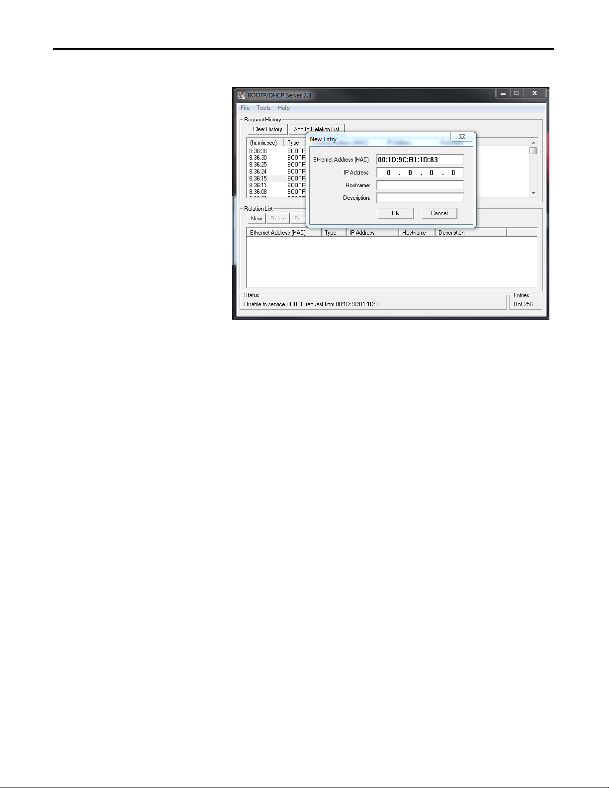
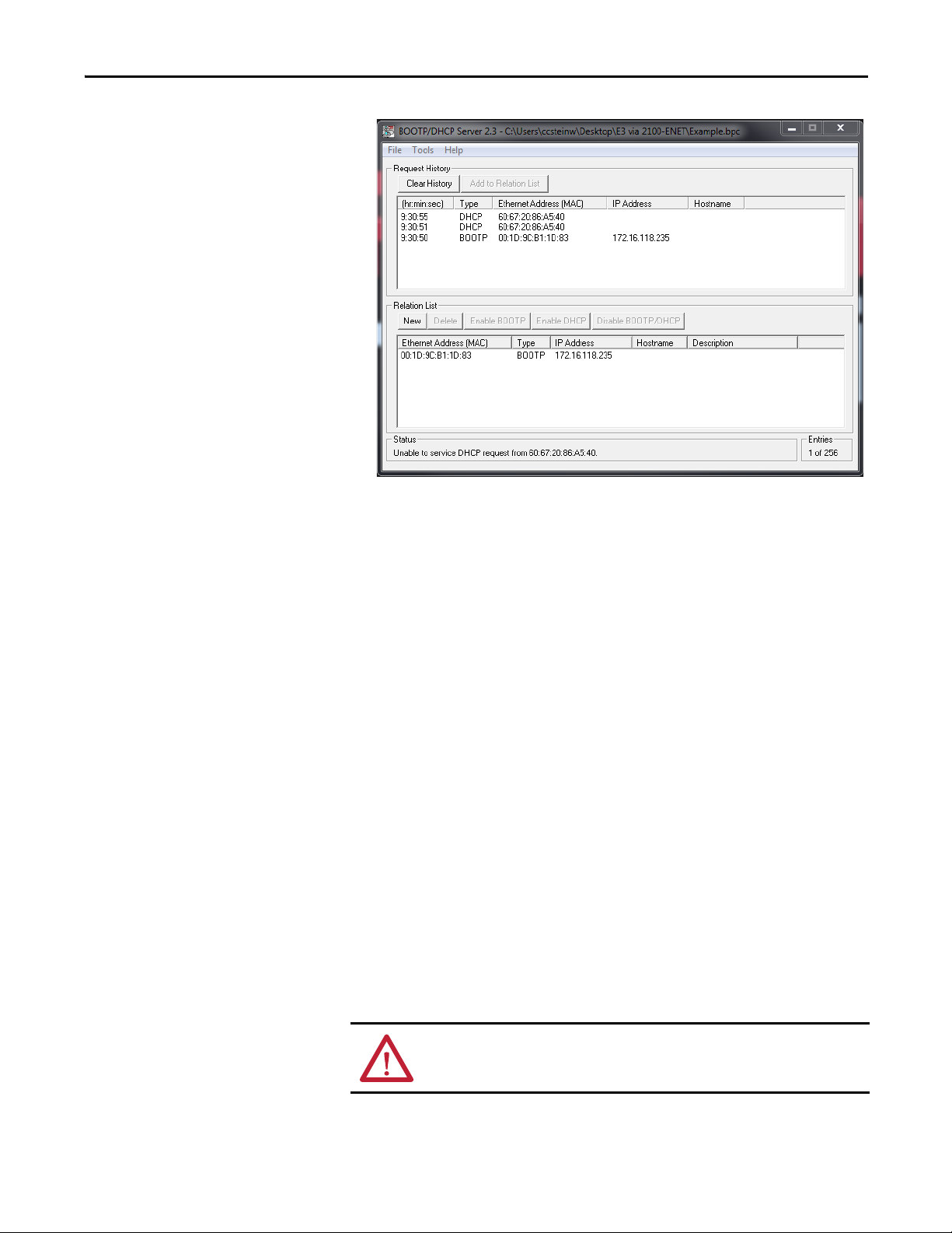
4. In the Request History area, double-click the desired node.
The New Entry dialog box appears.
Fill in the IP address, host, and description.
20 Rockwell Automation Publication 2100-UM006A-EN-P - July 2013
Chapter 3 Configure the Adapter
Fill in the IP address, host, and description.
5. Click OK.
6. Cycle power to the 2100-ENET adapter.
The newly assigned IP address appears in the Request History window.
TIP
The IP address is the only required information.
TIP
The end device’s DeviceNet address is configured for node 63 by following the
instructions provided in the appropriate end device user manual. The data rate
is configured for 500 Kpbs by following the instructions provided in the
appropriate end device user manual.
Rockwell Automation Publication 2100-UM006A-EN-P - July 2013 21
Configure the Adapter Chapter 3
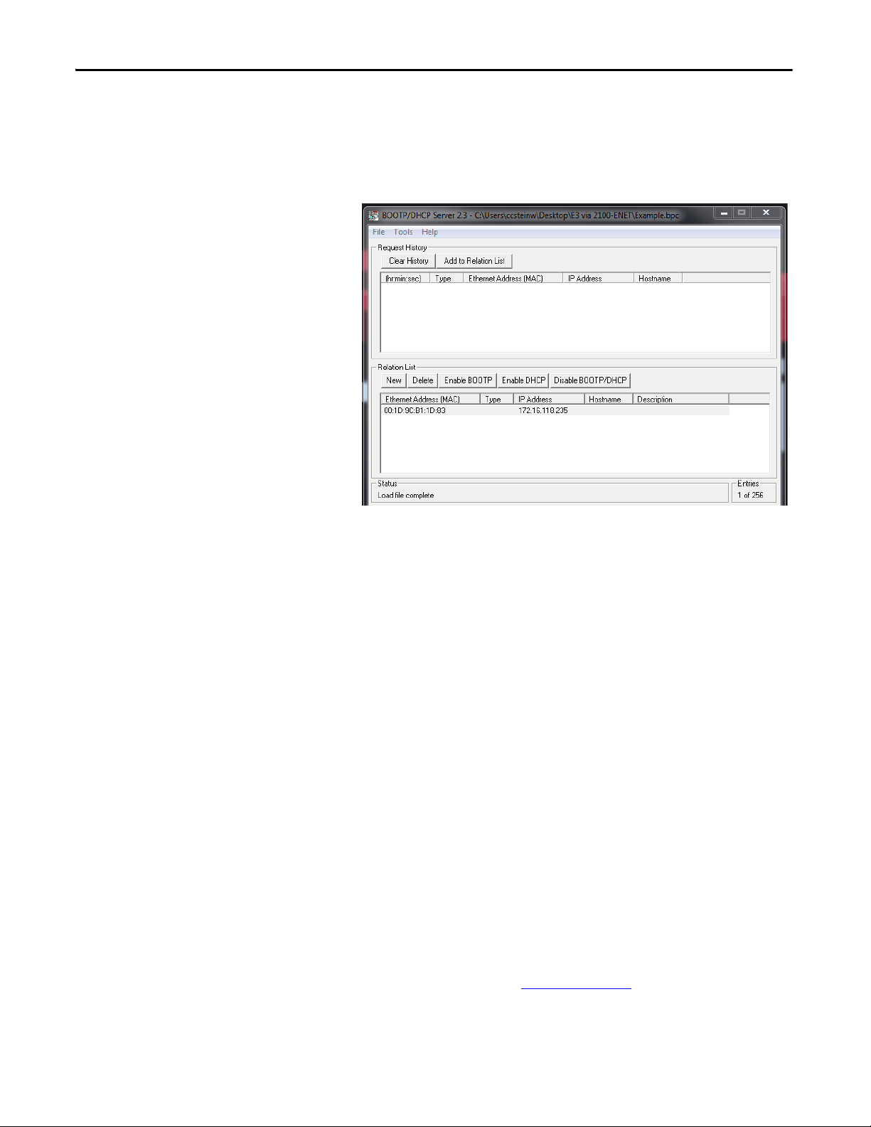
7. In the Relation List window, select the node and click Disable BOOTP/
DHCP.
This disables the BOOTP/DHCP functionality in the 2100-ENET
adapter, permanently assigning the applied IP address.
8. To save the configuration data, from the File menu, choose Save As and
provide an appropriate filename.
9. Cycle power to the 2100-ENET adapter.
Upon powerup, the 2100-ENET adapter disables the BOOTP protocol
and responds to network traffic that is addressed to the assigned IP address
every time it powers up.
Change an Assigned IP Address or Enable BOOTP in the 2100-ENET
Adapter
1. Connect your personal computer to the network to which the 2100-
ENET adapter is connected.
The adapter can be connected directly to your personal computer, if a
network does not exist.
2. Start your BOOTP program.
TIP
This information is useful for future configuration changes that use the BOOTP
server program.
Do not apply power to the 2100-ENET adapter until directed to do so.
22 Rockwell Automation Publication 2100-UM006A-EN-P - July 2013
Chapter 3 Configure the Adapter
3. Apply power to the 2100-ENET adapter.
4. From the File menu, choose Open.
5. Select your saved configuration data file and click OK.
The node configuration appears in the Relation List window.
6. To change the IP address or enable BOOTP, right-click the node and
choose Properties.
7. Cycle power to the 2100-ENET adapter.
The selected action takes effect upon powerup.
If the configuration file does not exist, click New in the Relation List
window and enter the Ethernet Address (MAC) printed on the product
data nameplate, along with the previously assigned IP address to add the
unit to the Relation List. Further actions described above can then be
executed on the desired unit.
Set the Data Rate
By default, the adapter is set to autodetect, so it automatically detects the data rate
and duplex setting used on the network.
Set the I/O Configuration
The I/O configuration determines the data that is sent to and from the E3 Plus or
825-P. Both the E3 Plus and the 825-P use Input and Output Assemblies to
determine the data being sent. See Tab le 1 o n pag e 4 2
for a list of input and
output assemblies supported by the Add-on Profile (AOP). For instructions on
how to change the input and output assemblies of the E3 Plus or 825-P, refer to
the appropriate user manual.
TIP
The end device’s DeviceNet address is configured for node 63 by following the
instructions provided in the appropriate end device user manual. The data rate
is configured for 500 Kpbs by following the instructions provided in the
appropriate end device user manual.

Rockwell Automation Publication 2100-UM006A-EN-P - July 2013 23
Configure the Adapter Chapter 3
Set a Fault Action
By default, when I/O communication is disrupted (for example, a cable is
disconnected) or the controller is idle (in Program mode or faulted), the end
device responds by faulting, if it is using I/O from the network. You can
configure a different response to a communication fault or an idle controller in
the end device. For instructions on how to change the fault or idle actions, refer
to the appropriate user manual.
ATTENTION: Risk of injury or equipment damage exists. Various parameters in
the end device let you determine the action of the adapter and the end device if
I/O communication is disrupted or the controller is idle. By default, these
parameters turn off the outputs of the end device. You can set these parameters
so that the outputs react as desired (for example, to keep the motor running).
Take precautions to be sure that the settings of these parameters do not create a
risk of injury or equipment damage. When commissioning the end device, verify
that your system responds correctly to various situations (for example, a
disconnected cable or faulted controller).
Loading...