


 Loading...
PowerFlex 20-COMM-E EtherNet/IP Adapter
Series A FRN 2.xxx
Series B FRN 4.xxx
User Manual
20-COMM-E EtherNet/IP Adapter User Manual
Important User Information Solid state equipment has operational characteristics differing from those of electromechanical equipment. Safety Guidelines for the Application,
Installation and Maintenance of Solid State Controls (Publication SGI-1.1 available from your local Rockwell Automation sales office or online at http:// www.rockwellautomation.com/literature) describes some important differences
between solid state equipment and hard-wired electromechanical devices. Because of this difference, and also because of the wide variety of uses for solid state equipment, all persons responsible for applying this equipment must satisfy themselves that each intended application of this equipment is acceptable.
In no event will Rockwell Automation, Inc. be responsible or liable for indirect or consequential damages resulting from the use or application of this equipment.
The examples and diagrams in this manual are included solely for illustrative purposes. Because of the many variables and requirements associated with any particular installation, Rockwell Automation, Inc. cannot assume responsibility or liability for actual use based on the examples and diagrams.
No patent liability is assumed by Rockwell Automation, Inc. with respect to use of information, circuits, equipment, or software described in this manual.
Reproduction of the contents of this manual, in whole or in part, without written permission of Rockwell Automation, Inc. is prohibited.
Throughout this manual, when necessary we use notes to make you aware of safety considerations.
WARNING: Identifies information about practices or
! |
circumstances that can cause an explosion in a hazardous |
|
|
|
environment, which may lead to personal injury or death, property |
|
damage, or economic loss. |
|
|
Important: Identifies information that is critical for successful application and understanding of the product.
ATTENTION: Identifies information about practices or
! |
circumstances that can lead to personal injury or death, property |
|
|
|
damage, or economic loss. Attentions help you identify a hazard, |
|
avoid a hazard, and recognize the consequences. |
|
|
Shock Hazard labels may be located on or inside the equipment (e.g., drive or motor) to alert people that dangerous voltage may be present.
Burn Hazard labels may be located on or inside the equipment (e.g., drive or motor) to alert people that surfaces may be at dangerous temperatures.
Allen-Bradley, Rockwell Software, Rockwell Automation, TechConnect, PowerFlex, SMC Flex, DPI, SCANport, Connected Components
Workbench, DriveExplorer, DriveExecutive, and DriveTools are trademarks of Rockwell Automation, Inc.
Trademarks not belonging to Rockwell Automation are property of their respective companies.
20-COMM-E EtherNet/IP Adapter User Manual
20-COMM-E EtherNet/IP Adapter User Manual

Summary of Changes
The information below summarizes the changes made to this manual since its last release (October 2012):
Description of Changes |
Page |
|
|
|
|
Added information about the compatible products. |
Throughout |
|
|
manual |
|
Added information for use with PowerFlex Digital DC drives. |
||
|
||
|
|
20-COMM-E EtherNet/IP Adapter User Manual
Publication 20COMM-UM010G-EN-P

soc-ii Summary of Changes
Notes:
20-COMM-E EtherNet/IP Adapter User Manual
Publication 20COMM-UM010G-EN-P

Table of Contents
Preface |
About This Manual |
|
|
Conventions Used in This Manual . . . . . . . . . . . . . . . . . . . . . . . . . . . . . . . . . . . . . . . . . . |
P-1 |
|
Rockwell Automation Support . . . . . . . . . . . . . . . . . . . . . . . . . . . . . . . . . . . . . . . . . . . . . |
P-2 |
|
Additional Resources . . . . . . . . . . . . . . . . . . . . . . . . . . . . . . . . . . . . . . . . . . . . . . . . . . . . |
P-2 |
Chapter 1 |
Getting Started |
|
|
Components. . . . . . . . . . . . . . . . . . . . . . . . . . . . . . . . . . . . . . . . . . . . . . . . . . . . . . . . . . . . |
1-1 |
|
Features . . . . . . . . . . . . . . . . . . . . . . . . . . . . . . . . . . . . . . . . . . . . . . . . . . . . . . . . . . . . . . . |
1-2 |
|
Compatible Products . . . . . . . . . . . . . . . . . . . . . . . . . . . . . . . . . . . . . . . . . . . . . . . . . . . . . |
1-3 |
|
Required Equipment . . . . . . . . . . . . . . . . . . . . . . . . . . . . . . . . . . . . . . . . . . . . . . . . . . . . . |
1-3 |
|
Safety Precautions. . . . . . . . . . . . . . . . . . . . . . . . . . . . . . . . . . . . . . . . . . . . . . . . . . . . . . . |
1-5 |
|
Quick Start . . . . . . . . . . . . . . . . . . . . . . . . . . . . . . . . . . . . . . . . . . . . . . . . . . . . . . . . . . . . |
1-6 |
Chapter 2 |
Installing the Adapter |
|
|
Preparing for an Installation . . . . . . . . . . . . . . . . . . . . . . . . . . . . . . . . . . . . . . . . . . . . . . . |
2-1 |
|
Setting the Web Pages Switch (only Series B Adapter, Firmware 3.xxx or Later). . . . . . |
2-2 |
|
Connecting the Adapter to the Drive. . . . . . . . . . . . . . . . . . . . . . . . . . . . . . . . . . . . . . . . . |
2-3 |
|
Connecting the Adapter to the Network . . . . . . . . . . . . . . . . . . . . . . . . . . . . . . . . . . . . . . |
2-6 |
|
Applying Power. . . . . . . . . . . . . . . . . . . . . . . . . . . . . . . . . . . . . . . . . . . . . . . . . . . . . . . . . |
2-6 |
|
Commissioning the Adapter . . . . . . . . . . . . . . . . . . . . . . . . . . . . . . . . . . . . . . . . . . . . . . . |
2-8 |
Chapter 3 |
Configuring the Adapter |
|
|
Configuration Tools. . . . . . . . . . . . . . . . . . . . . . . . . . . . . . . . . . . . . . . . . . . . . . . . . . . . . . |
3-1 |
|
Using the PowerFlex 7-Class HIM to Access Parameters . . . . . . . . . . . . . . . . . . . . . . . . |
3-2 |
|
Using BOOTP Server to Set the IP Address, Subnet Mask, and Gateway Address . . . . . |
3-3 |
|
Using Parameters to Set the IP Address, Subnet Mask, and Gateway Address . . . . . . . . |
3-5 |
|
Setting the Data Rate. . . . . . . . . . . . . . . . . . . . . . . . . . . . . . . . . . . . . . . . . . . . . . . . . . . . . |
3-7 |
|
Setting the I/O Configuration . . . . . . . . . . . . . . . . . . . . . . . . . . . . . . . . . . . . . . . . . . . . . . |
3-7 |
|
Selecting Master-Slave or Peer-to-Peer Hierarchy . . . . . . . . . . . . . . . . . . . . . . . . . . . . . . |
3-8 |
|
Setting the Reference Adjustment. . . . . . . . . . . . . . . . . . . . . . . . . . . . . . . . . . . . . . . . . . |
3-13 |
|
Setting a Fault Action . . . . . . . . . . . . . . . . . . . . . . . . . . . . . . . . . . . . . . . . . . . . . . . . . . . |
3-14 |
|
Setting Web Access Control . . . . . . . . . . . . . . . . . . . . . . . . . . . . . . . . . . . . . . . . . . . . . . |
3-15 |
|
Resetting the Adapter . . . . . . . . . . . . . . . . . . . . . . . . . . . . . . . . . . . . . . . . . . . . . . . . . . . |
3-16 |
|
Viewing the Adapter Status Using Parameters . . . . . . . . . . . . . . . . . . . . . . . . . . . . . . . . |
3-17 |
|
Updating the Adapter Firmware . . . . . . . . . . . . . . . . . . . . . . . . . . . . . . . . . . . . . . . . . . . |
3-17 |
Chapter 4 |
Configuring the I/O |
|
|
Using RSLinx Classic Software . . . . . . . . . . . . . . . . . . . . . . . . . . . . . . . . . . . . . . . . . . . . |
4-1 |
|
ControlLogix Controller Example . . . . . . . . . . . . . . . . . . . . . . . . . . . . . . . . . . . . . . . . . . |
4-2 |
|
Limitations Using a PLC-5, SLC 500, or MicroLogix 1100/1400 Controller . . . . . . . . |
4-22 |
|
PLC-5 Controller Example . . . . . . . . . . . . . . . . . . . . . . . . . . . . . . . . . . . . . . . . . . . . . . . |
4-23 |
|
SLC 500 Controller Example . . . . . . . . . . . . . . . . . . . . . . . . . . . . . . . . . . . . . . . . . . . . . |
4-31 |
|
MicroLogix 1100/1400 Controller Example. . . . . . . . . . . . . . . . . . . . . . . . . . . . . . . . . . |
4-39 |
20-COMM-E EtherNet/IP Adapter User Manual
Publication 20COMM-UM010G-EN-P

ii Table of Contents
Chapter 5 |
Using the I/O |
|
|
About I/O Messaging. . . . . . . . . . . . . . . . . . . . . . . . . . . . . . . . . . . . . . . . . . . . . . . . . . . . . |
5-1 |
|
Understanding the I/O Image. . . . . . . . . . . . . . . . . . . . . . . . . . . . . . . . . . . . . . . . . . . . . . . |
5-2 |
|
Using Logic Command/Status. . . . . . . . . . . . . . . . . . . . . . . . . . . . . . . . . . . . . . . . . . . . . . |
5-6 |
|
Using Reference/Feedback . . . . . . . . . . . . . . . . . . . . . . . . . . . . . . . . . . . . . . . . . . . . . . . . |
5-6 |
|
Using Datalinks . . . . . . . . . . . . . . . . . . . . . . . . . . . . . . . . . . . . . . . . . . . . . . . . . . . . . . . . . |
5-9 |
|
Example Ladder Logic Program Information . . . . . . . . . . . . . . . . . . . . . . . . . . . . . . . . . |
5-11 |
|
ControlLogix Controller Example. . . . . . . . . . . . . . . . . . . . . . . . . . . . . . . . . . . . . . . . . . |
5-11 |
|
PLC-5, SLC 500, or MicroLogix 1100/1400 Controller Example . . . . . . . . . . . . . . . . . |
5-21 |
Chapter 6 |
Using Explicit Messaging |
|
|
About Explicit Messaging . . . . . . . . . . . . . . . . . . . . . . . . . . . . . . . . . . . . . . . . . . . . . . . . . |
6-2 |
|
Performing Explicit Messages. . . . . . . . . . . . . . . . . . . . . . . . . . . . . . . . . . . . . . . . . . . . . . |
6-3 |
|
ControlLogix Controller Examples . . . . . . . . . . . . . . . . . . . . . . . . . . . . . . . . . . . . . . . . . . |
6-4 |
|
PLC-5 Controller Examples . . . . . . . . . . . . . . . . . . . . . . . . . . . . . . . . . . . . . . . . . . . . . . |
6-23 |
|
SLC 500 Controller Examples. . . . . . . . . . . . . . . . . . . . . . . . . . . . . . . . . . . . . . . . . . . . . |
6-29 |
|
MicroLogix 1100/1400 Controller Examples . . . . . . . . . . . . . . . . . . . . . . . . . . . . . . . . . |
6-53 |
Chapter 7 |
Troubleshooting |
|
|
Understanding the Status Indicators . . . . . . . . . . . . . . . . . . . . . . . . . . . . . . . . . . . . . . . . . |
7-1 |
|
PORT Status Indicator . . . . . . . . . . . . . . . . . . . . . . . . . . . . . . . . . . . . . . . . . . . . . . . . . . . . |
7-2 |
|
MOD Status Indicator . . . . . . . . . . . . . . . . . . . . . . . . . . . . . . . . . . . . . . . . . . . . . . . . . . . . |
7-2 |
|
NET A Status Indicator . . . . . . . . . . . . . . . . . . . . . . . . . . . . . . . . . . . . . . . . . . . . . . . . . . . |
7-3 |
|
NET B Status Indicator . . . . . . . . . . . . . . . . . . . . . . . . . . . . . . . . . . . . . . . . . . . . . . . . . . . |
7-3 |
|
Viewing Adapter Diagnostic Items . . . . . . . . . . . . . . . . . . . . . . . . . . . . . . . . . . . . . . . . . . |
7-4 |
|
Viewing and Clearing Events. . . . . . . . . . . . . . . . . . . . . . . . . . . . . . . . . . . . . . . . . . . . . . . |
7-6 |
Chapter 8 |
Viewing the Adapter Web Pages |
|
|
Enabling the Adapter Web Pages. . . . . . . . . . . . . . . . . . . . . . . . . . . . . . . . . . . . . . . . . . . . |
8-1 |
|
Viewing the Web Pages . . . . . . . . . . . . . . . . . . . . . . . . . . . . . . . . . . . . . . . . . . . . . . . . . . . |
8-1 |
|
Process Display Pop-up Window. . . . . . . . . . . . . . . . . . . . . . . . . . . . . . . . . . . . . . . . . . . . |
8-4 |
|
TCP/IP Configuration Web Page . . . . . . . . . . . . . . . . . . . . . . . . . . . . . . . . . . . . . . . . . . . . |
8-5 |
|
Configure E-mail Notification Web Page . . . . . . . . . . . . . . . . . . . . . . . . . . . . . . . . . . . . . |
8-6 |
|
Device Information Pages . . . . . . . . . . . . . . . . . . . . . . . . . . . . . . . . . . . . . . . . . . . . . . . . . |
8-9 |
Chapter 9 |
Using the Adapter in a DPI External Comms Kit (20-XCOMM-DC-BASE) |
|
|
Installing the Adapter . . . . . . . . . . . . . . . . . . . . . . . . . . . . . . . . . . . . . . . . . . . . . . . . . . . . |
9-1 |
|
I/O Board Option (20-XCOMM-IO-OPT1) . . . . . . . . . . . . . . . . . . . . . . . . . . . . . . . . . . . |
9-2 |
|
Understanding the I/O Image (Drive + I/O Option) . . . . . . . . . . . . . . . . . . . . . . . . . . . . . |
9-2 |
|
Configuring the Adapter to Use the Optional I/O Data . . . . . . . . . . . . . . . . . . . . . . . . . . . |
9-3 |
|
Viewing Optional I/O Diagnostic Items . . . . . . . . . . . . . . . . . . . . . . . . . . . . . . . . . . . . . . |
9-4 |
Appendix A |
Specifications |
|
|
Communications . . . . . . . . . . . . . . . . . . . . . . . . . . . . . . . . . . . . . . . . . . . . . . . . . . . . . . . . |
A-1 |
|
Electrical . . . . . . . . . . . . . . . . . . . . . . . . . . . . . . . . . . . . . . . . . . . . . . . . . . . . . . . . . . . . . . |
A-1 |
|
Mechanical. . . . . . . . . . . . . . . . . . . . . . . . . . . . . . . . . . . . . . . . . . . . . . . . . . . . . . . . . . . . . |
A-2 |
|
Environmental . . . . . . . . . . . . . . . . . . . . . . . . . . . . . . . . . . . . . . . . . . . . . . . . . . . . . . . . . . |
A-2 |
|
Regulatory Compliance . . . . . . . . . . . . . . . . . . . . . . . . . . . . . . . . . . . . . . . . . . . . . . . . . . . |
A-2 |
20-COMM-E EtherNet/IP Adapter User Manual
Publication 20COMM-UM010G-EN-P

Table of Contents |
iii |
|
|
Appendix B Adapter Parameters
Parameter List . . . . . . . . . . . . . . . . . . . . . . . . . . . . . . . . . . . . . . . . . . . . . . . . . . . . . . . . . . B-1
Appendix C EtherNet/IP Objects
Identity Object. . . . . . . . . . . . . . . . . . . . . . . . . . . . . . . . . . . . . . . . . . . . . . . . . . . . . . . . . . C-2
Assembly Object . . . . . . . . . . . . . . . . . . . . . . . . . . . . . . . . . . . . . . . . . . . . . . . . . . . . . . . . C-3
Register Object . . . . . . . . . . . . . . . . . . . . . . . . . . . . . . . . . . . . . . . . . . . . . . . . . . . . . . . . . C-4
Parameter Object . . . . . . . . . . . . . . . . . . . . . . . . . . . . . . . . . . . . . . . . . . . . . . . . . . . . . . . . C-5
Parameter Group Object . . . . . . . . . . . . . . . . . . . . . . . . . . . . . . . . . . . . . . . . . . . . . . . . . . C-7
PCCC Object. . . . . . . . . . . . . . . . . . . . . . . . . . . . . . . . . . . . . . . . . . . . . . . . . . . . . . . . . . . C-8
DPI Device Object . . . . . . . . . . . . . . . . . . . . . . . . . . . . . . . . . . . . . . . . . . . . . . . . . . . . . C-13
DPI Parameter Object . . . . . . . . . . . . . . . . . . . . . . . . . . . . . . . . . . . . . . . . . . . . . . . . . . . C-16
DPI Fault Object . . . . . . . . . . . . . . . . . . . . . . . . . . . . . . . . . . . . . . . . . . . . . . . . . . . . . . . C-22
DPI Alarm Object . . . . . . . . . . . . . . . . . . . . . . . . . . . . . . . . . . . . . . . . . . . . . . . . . . . . . . C-24
DPI Diagnostic Object . . . . . . . . . . . . . . . . . . . . . . . . . . . . . . . . . . . . . . . . . . . . . . . . . . C-26
DPI Time Object . . . . . . . . . . . . . . . . . . . . . . . . . . . . . . . . . . . . . . . . . . . . . . . . . . . . . . . C-28
Host DPI Parameter Object . . . . . . . . . . . . . . . . . . . . . . . . . . . . . . . . . . . . . . . . . . . . . . . C-30
TCP/IP Interface Object . . . . . . . . . . . . . . . . . . . . . . . . . . . . . . . . . . . . . . . . . . . . . . . . . C-36
Ethernet Link Object . . . . . . . . . . . . . . . . . . . . . . . . . . . . . . . . . . . . . . . . . . . . . . . . . . . . C-37
Appendix D Logic Command/Status Words
PowerFlex 70/700/700H, and 700L (with 700 Control) Drives . . . . . . . . . . . . . . . . . . . . D-1 PowerFlex 700S (Phase II Control) and 700L (with 700S Control) Drives . . . . . . . . . . . D-3 PowerFlex 750-Series Drives . . . . . . . . . . . . . . . . . . . . . . . . . . . . . . . . . . . . . . . . . . . . . . D-5 PowerFlex Digital DC Drives . . . . . . . . . . . . . . . . . . . . . . . . . . . . . . . . . . . . . . . . . . . . . . D-7
Glossary
Index
20-COMM-E EtherNet/IP Adapter User Manual
Publication 20COMM-UM010G-EN-P

iv |
Table of Contents |
|
|
20-COMM-E EtherNet/IP Adapter User Manual
Publication 20COMM-UM010G-EN-P
Preface
About This Manual
Topic |
Page |
|
|
Conventions Used in This Manual |
P-1 |
|
|
Rockwell Automation Support |
P-2 |
|
|
Additional Resources |
P-2 |
|
|
Conventions Used in This
Manual
This manual provides information about the adapter and using it with PowerFlex 7-Class (Architecture-Class) drives. The adapter can be used with other products that support a DPI™ adapter, such as the DPI External Comms Kit (20-XCOMM-DC-BASE). See the documentation for your product for specific information about how it works with the adapter.
The following conventions are used throughout this manual:
•Parameter names are shown in the format Parameter xx - [*]. The xx represents the parameter number. The * represents the parameter name— for example Parameter 01 - [DPI Port].
•Menu commands are shown in bold type face and follow the format Menu > Command. For example, if you read ‘Select File > Open’, you should click the File menu and then click the Open command.
•The firmware revision number (FRN) is displayed as FRN X.xxx, where ‘X’ is the major revision number and ‘xxx’ is the minor revision number.
•The screen images in this manual resulted from using the following software:
–RSLinx® Classic software, version 2.51
–RSLogix™ 5 software, version 7.20
–RSLogix 500 software, version 7.20
–RSLogix 5000 software, version 16.00
Different versions of the software may have screens that vary in appearance, and differences in procedures.
20-COMM-E EtherNet/IP Adapter User Manual
Publication 20COMM-UM010G-EN-P

P-2 About This Manual
Rockwell Automation
Support
Rockwell Automation offers support services worldwide, with over 75 sales and support offices, over 500 authorized distributors, and over 250 authorized systems integrators located through the United States alone. In addition, Rockwell Automation representatives are in every major country in the world.
Local Product Support
Contact your local Rockwell Automation representative for the following:
•Sales and order support
•Product technical training
•Warranty support
•Support service agreements
Technical Product Assistance
For technical assistance, please review the information in Chapter 7, Troubleshooting, first. If you still have problems, then access the Allen-Bradley Technical Support website at www.ab.com/support/abdrives or contact Rockwell Automation.
Additional Resources |
These documents contain additional information concerning related |
||
|
products from Rockwell Automation. |
||
|
|
|
|
Resource |
|
|
Description |
|
|
||
PowerFlex 7-Class DPI (Drive Peripheral Interface) Network Communication Adapter Installation |
Information on the installation of PowerFlex® 20-COMM-x |
||
Instructions, publication 20COMM-IN004 |
|
|
Network Communication Adapters. |
|
|
|
|
EtherNet/IP Media Planning and Installation Manual, ODVA publication 148 (1) |
|
Information on the planning, installation, and techniques used |
|
|
|
|
to implement an EtherNet/IP network. |
EtherNet/IP Network Infrastructure Guidelines, ODVA publication 35 (1) |
|
||
|
|
||
Ethernet Design Considerations Reference Manual, publication ENET-RM002 |
|
|
|
|
|
||
Connected Components Workbench website http://www.ab.com/support/abdrives/webupdate/ |
Information on the Connected Components Workbench™ |
||
software.html, and online help |
|
|
software tool—and includes a link for free software download. |
|
|
|
|
DriveExplorer website http://www.ab.com/drives/driveexplorer/, and online help (2) |
|
Information on using the DriveExplorer™ software tool. |
|
DriveExecutive website http://www.ab.com/drives/drivetools/, and online help (2) |
|
Information on using the DriveExecutive™ software tool. |
|
PowerFlex 20-HIM-A3/-A5/-C3S/-C5S HIM Quick Reference, publication 20HIM-QR001 |
Information on using the PowerFlex 20-HIM-A3, 20-HIM-A5, |
||
|
|
|
20-HIM-C3S, and 20-HIM-C5S HIMs. |
|
|
|
|
PowerFlex 20-HIM-A6/-C6S HIM (Human Interface Module) User Manual, publication |
20HIM-UM001 |
Information on installing and using the PowerFlex 20-HIM-A6 |
|
|
|
|
and 20-HIM-C6S HIMs. |
|
|
|
|
PowerFlex 70 User Manual, publication 20A-UM001 |
|
Information on installing and programming PowerFlex 70 |
|
PowerFlex 70/700 Reference Manual, publication PFLEX-RM001 |
|
standard control and enhanced control drives. |
|
PowerFlex 70 Enhanced Control and 700 Vector Control Reference Manual, publication |
PFLEX-RM004 |
|
|
|
|
|
|
PowerFlex 700 Series A User Manual, publication 20B-UM001 |
|
Information on installing and programming PowerFlex 700 |
|
PowerFlex 700 Series B User Manual, publication 20B-UM002 |
|
standard control and vector control Series A drives, and |
|
PowerFlex 70/700 Reference Manual, publication PFLEX-RM001 |
|
PowerFlex 700 vector control Series B drives. |
|
PowerFlex 70 Enhanced Control and 700 Vector Control Reference Manual, publication |
PFLEX-RM004 |
|
|
|
|
|
|
PowerFlex 700H Installation Instructions, publication PFLEX-IN006 |
|
Information on installing and programming PowerFlex 700H |
|
PowerFlex 700H Programming Manual, publication 20C-PM001 |
|
drives. |
|
|
|
|
|
20-COMM-E EtherNet/IP Adapter User Manual
Publication 20COMM-UM010G-EN-P

|
About This Manual |
P-3 |
|
|
|
|
|
|
Resource |
Description |
|
|
|
|
PowerFlex 700S w/Phase I Control Installation Manual (Frames 1…6), publication 20D-IN024 |
Information on installing and programming PowerFlex 700S |
|
PowerFlex 700S w/Phase I Control Installation Manual (Frames 9 and 10), publication PFLEX-IN006 |
drives. |
|
PowerFlex 700S w/Phase I Control User Manual (All Frame Sizes), publication 20D-UM001 |
|
|
PowerFlex 700S w/Phase I Control Reference Manual, publication PFLEX-RM002 |
|
|
PowerFlex 700S w/Phase II Control Installation Manual (Frames 1…6), publication 20D-IN024 |
|
|
PowerFlex 700S w/Phase II Control Installation Manual (Frames 9…14), publication PFLEX-IN006 |
|
|
PowerFlex 700S w/Phase II Control Programming Manual (All Frame Sizes), publication 20D-PM001 |
|
|
PowerFlex 700S w/Phase II Control Reference Manual, publication PFLEX-RM003 |
|
|
|
|
|
PowerFlex 700L User Manual, publication 20L-UM001 |
Information on installing and programming PowerFlex 700L |
|
|
Liquid-Cooled AC drives. |
|
|
|
|
PowerFlex 750-Series Drive Installation Instructions, publication 750-IN001 |
Information on installing and programming PowerFlex |
|
PowerFlex 750-Series Drive Programming Manual, publication 750-PM001 |
750-Series AC drives. |
|
PowerFlex 20-750-ENETR Dual-port EtherNet/IP Option Module, publication 750COM-UM008 |
|
|
PowerFlex 755 Drive Embedded EtherNet/IP Adapter User Manual, publication 750COM-UM001 |
|
|
20-750-20COMM and 20-750-20COMM-F1 Communication Carrier Cards Installation Instructions, |
|
|
publication 750COM-IN001 |
|
|
|
|
|
PowerFlex Digital DC Drive User Manual, publication 20P-UM001 |
Information on installing and programming PowerFlex Digital |
|
|
DC drives. |
|
|
|
|
Getting Results with RSLinx Guide, publication LINX-GR001, and online help (2) |
Information on using RSLinx Classic software. |
|
RSLogix Emulate 5/500 Getting Results Guide, publication EMULAT-GR002, and online help |
Information on installing and navigating the RSLogix Emulate |
|
|
software for ladder logic programming with Allen-Bradley® |
|
|
PLC-5® and SLC™ 500 processors. |
|
RSLogix 500 Getting Results Guide, publication LG500-GR002, and online help (2) |
Information on using RSLogix 500 software tool. |
|
RSLogix 5000 PIDE Autotuner Getting Results Guide, publication PIDE-GR001, and online help (2) |
Information on using RSLogix 5000 software tool. |
|
EtherNet/IP Modules in Logix5000 Control Systems User Manual, publication ENET-UM001 |
Information on using the ControlLogix® 1756-ENBT or |
|
|
1756-EN2T EtherNet/IP communication modules with the |
|
|
Logix5000 controller and communicating with various devices |
|
|
on the EtherNet/IP network. |
|
|
|
|
Enhanced and Ethernet PLC-5 Programmable Controllers User Manual, publication 1785-UM012 |
Information to help design, operate and maintain an Enhanced |
|
|
and Ethernet PLC-5 programmable controller system. |
|
|
|
|
SLC 500 Modular Hardware Style User Manual, publication 1747-UM011 |
Information on installing, using, and troubleshooting the SLC |
|
|
500 controller with 1747-L5-xxx module. |
|
|
|
|
MicroLogix 1100 Programmable Controllers User Manual, publication 1763-UM001 |
Information on installing, using, and troubleshooting the |
|
MicroLogix 1400 Programmable Controllers User Manual, publication 1766-UM001 |
MicroLogix™ 1100 and MicroLogix 1400 controllers. |
|
|
|
|
(1)Use this link to the ODVA EtherNet/IP library: http://odva.org/Home/ODVATECHNOLOGIES/EtherNetIP/EtherNetIPLibrary/tabid/76/Default.aspx
(2)The online help is installed with the software.
Documentation can be obtained online at http:// literature.rockwellautomation.com. To order paper copies of technical documentation, contact your local Rockwell Automation distributor or sales representative.
To find your local Rockwell Automation distributor or sales representative, visit http://www.rockwellautomation.com/locations.
For information such as firmware updates or answers to drive-related questions, go to the Drives Service & Support website at http:// www.ab.com/support/abdrives and click the Downloads or Knowledgebase link.
20-COMM-E EtherNet/IP Adapter User Manual
Publication 20COMM-UM010G-EN-P

P-4 About This Manual
Notes:
20-COMM-E EtherNet/IP Adapter User Manual
Publication 20COMM-UM010G-EN-P
Chapter 1
Getting Started
The adapter is intended for installation in a PowerFlex 7-Class drive and is used for network communication. The 20-COMM-E Series B adapter, firmware 3.xxx or later, can also be installed in an External DPI Comms Kit (20-XCOMM-DC-BASE).
For PowerFlex 750-Series drives, we recommend using the 20-750-ENETR Dual-port EtherNet/IP option module or the embedded EtherNet/IP adapter (only in PowerFlex 755 drives) instead of the 20-COMM-E adapter.
However, this manual does include information about using the 20-COMM-E adapter with PowerFlex 750-Series drives—but there are operating limitations. For details, see Compatible Products on page 1-3.
Topic |
Page |
|
|
Components |
1-1 |
|
|
Features |
1-2 |
|
|
Compatible Products |
1-3 |
|
|
Required Equipment |
1-3 |
|
|
Safety Precautions |
1-5 |
|
|
Quick Start |
1-6 |
|
|
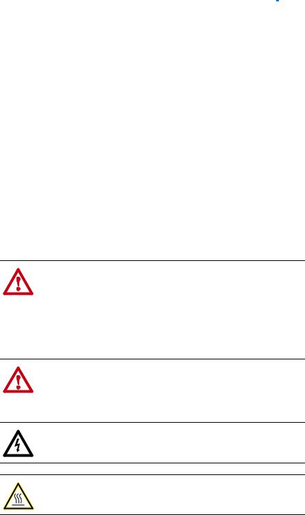
Components |
|
|
|
|
|
|
|
Not provided on Series A adapter |
|
|
|
|
|
Item |
Part |
|
Description |
|
|
|
|
|
Status Indicators |
|
Four status indicators that indicate the status of the DPI, the |
|
|
|
adapter, and network connection. See Chapter 7, Troubleshooting. |
|
|
|
|
|
DPI Connector |
|
A 20-pin, single-row shrouded male header. An Internal Interface |
|
|
|
cable is connected to this connector and a connector on the drive. |
|
|
|
|
|
Ethernet Connector |
RJ-45 connector for the Ethernet network cable. The connector is |
|
|
|
|
CAT-5 compliant to ensure reliable data transfer on 100Base-TX |
|
|
|
Ethernet connections. |
|
|
|
|
|
Web Pages Switch |
Enables or disables the adapter web pages. See Setting the Web |
|
|
(SW2) |
|
Pages Switch (only Series B Adapter, Firmware 3.xxx or Later) on |
|
|
|
page 2-2. SW1 is unused. |
|
|
|
|
20-COMM-E EtherNet/IP Adapter User Manual
Publication 20COMM-UM010G-EN-P

1-2 Getting Started
Features |
The features of the adapter include the following: |
•Typical mounting in a PowerFlex 7-Class drive. The 20-COMM-E Series B adapter, firmware 3.xxx or later, can also be installed in a DPI External Comms Kit and used with the kit’s optional I/O board. See Chapter 9, Using the Adapter in a DPI External Comms Kit (20-XCOMM-DC-BASE) for more information.
DPI External Comms Kit Compatibility
20-COMM-E Adapter |
Operation With |
||
|
|
|
|
|
Firmware |
DPI External Comms Kit |
Optional I/O Board |
Series |
Revision |
(20-XCOMM-DC-BASE) |
(20-XCOMM-IO-OPT1) |
|
|
|
|
A |
2.xxx and earlier |
No |
No |
|
|
|
|
B |
3.xxx and later |
Yes |
Yes |
|
|
|
|
•Captive screws to secure and ground the adapter to the drive or, when mounted in a DPI External Comms Kit, to the kit’s metal enclosure.
•Compatibility with various configuration tools to configure the adapter and connected host drive, including the following tools:
–PowerFlex HIM (Human Interface Module) on the drive, if available
–Connected Components Workbench software, version 1.02 or later
–DriveExplorer software, version 2.01 or later
–DriveExecutive software, version 3.01 or later
Additionally, you can use a BOOTP server to configure the network address for the adapter.
•Status indicators that report the status of the drive communications, the adapter, and network. They are visible when the drive cover is open or closed.
•Parameter-configured I/O (Logic Command/Reference and up to four pairs of Datalinks) to accommodate application requirements.
•Explicit Messaging support.
•Master-Slave or Peer-to-Peer hierarchy that can be configured to transmit data to and from either a controller or another PowerFlex drive on the network.
•User-defined fault actions to determine how the adapter and connected PowerFlex drive respond to the following:
–I/O messaging communication disruptions (Comm Flt Action)
–Controllers in idle mode (Idle Flt Action)
•Web pages, viewed by using a web browser, that show information about the adapter, its connected host drive, and DPI devices connected to the drive.
•Configurable e-mail messaging to desired addresses when selected drive faults occur and/or are cleared, and/or when the adapter takes a communication or idle fault action.
•Access to any PowerFlex drive and its connected peripherals on the network to which the adapter is connected.
20-COMM-E EtherNet/IP Adapter User Manual
Publication 20COMM-UM010G-EN-P

Getting Started |
1-3 |
|
|
Compatible Products |
At the time of publication, the adapter is compatible with the following |
|
|
products: |
|
|
|
|
|
• PowerFlex 70 drives with standard or enhanced control |
• PowerFlex 750-Series drives (1) |
|
• PowerFlex 700 drives with standard or vector control |
• PowerFlex Digital DC drives |
|
• PowerFlex 700H drives |
• DPI External Comms Kit |
|
• PowerFlex 700S drives with Phase I or Phase II control |
• SMC™ Flex smart motor controllers |
|
• PowerFlex 700L drives with 700 vector control or 700S control |
• SMC-50 smart motor controllers |
(1)The 20-COMM-E adapter can be used with PowerFlex 750-Series drives, but the drive must have firmware revision 4.001 or later. Also, the 20-COMM-E adapter has the following limitations and differences:
-Only the first 16 bits of the Logic Command and Logic Status words are used.
-Speed Reference and Feedback scaling are Hz (or RPM) x 1000 (depending on the setting of drive parameter 300 - [Speed Units].
Instead of using the 20-COMM-E adapter with the PowerFlex 753 drive, the 20-750-ENETR Dual-port EtherNet/IP option module should be used whenever possible. Please see the PowerFlex 750-Series AC Drives Programming Manual, publication 750-PM001, for drive parameter information and t he 20-750-ENETR Dual-Port EtherNet/IP Option Module User Manual, publication 750COM-UM008, for network communication module information. For a PowerFlex 755 drive, it is recommended to use its embedded EtherNet/IP adapter instead of the 20-COMM-E adapter and its inherent limitations.
Required Equipment |
Some of the equipment that is required for use with the adapter is shipped |
|
with the adapter, but some you must supply yourself. |
|
Equipment Shipped with the Adapter |
|
When you unpack the adapter, verify that the package includes the following: |
|
One 20-COMM-E EtherNet/IP adapter |
|
One 2.54 cm (1 in.) long and one 15.24 cm (6 in.) long Internal |
|
Interface cable (only one cable is needed to connect the adapter to the |
|
drive; for which cable to use, see Figure 2.2 on page 2-4) |
|
One PowerFlex 7-Class DPI (Drive Peripheral Interface) Network |
|
Communication Adapter Installation Instructions, publication |
|
20COMM-IN004 |
|
TIP: When mounting the 20-COMM-E adapter in a PowerFlex 750-Series |
|
drive, you must use a 20-750-20COMM or 20-750-20COMM-F1 |
|
Communication Carrier Card, publication 750COM-IN001—and the |
|
20-COMM-E adapter must have firmware revision 4.001 or later. |
|
User-Supplied Equipment |
|
To install and configure the adapter, you must supply the following: |
|
A small flathead screwdriver |
|
Ethernet cable (for details, see the EtherNet/IP Media Planning and |
|
Installation Manual, ODVA publication 148 available on the ODVA |
|
website at http://odva.org/Home/ODVATECHNOLOGIES/EtherNetIP/ |
|
EtherNetIPLibrary/tabid/76/Default.aspx) |
20-COMM-E EtherNet/IP Adapter User Manual
Publication 20COMM-UM010G-EN-P

1-4 Getting Started
Ethernet switch (for details, see the Ethernet Design Considerations Reference Manual, publication ENET-RM002)
Drive and adapter configuration tool, such as the following:
–PowerFlex 20-HIM-xx HIM
–Connected Components Workbench software, version 1.02 or later
Connected Components Workbench is the recommended stand-alone software tool for use with PowerFlex drives. You can obtain a free copy by:
•Internet download at http://www.ab.com/support/abdrives/ webupdate/software.html
•Requesting a DVD at http://www.ab.com/onecontact/controllers/ micro800/
Your local distributor may also have copies of the DVD available.
Connected Components Workbench software cannot be used to configure SCANport-based drives or Bulletin 160 drives.
–DriveExplorer software, version 2.01 or later
This software tool has been discontinued and is now available as freeware at http://www.ab.com/support/abdrives/webupdate/ software.html. There are no plans to provide future updates to this tool and the download is being provided ‘as-is’ for users that lost their DriveExplorer CD, or need to configure legacy products not supported by Connected Components Workbench software.
–DriveExecutive software, version 3.01 or later
A Lite version of DriveExecutive software ships with RSLogix 5000, RSNetWorx MD, FactoryTalk AssetCentre, and ItelliCENTER software. All other versions are purchasable items:
•9303-4DTE01ENE Drive Executive software
•9303-4DTS01ENE DriveTools SP Suite (includes DriveExecutive and DriveObserver software)
•9303-4DTE2S01ENE DriveExecutive software upgrade to DriveTools SP Suite (adds DriveObserver software)
DriveExecutive software updates (patches, and so forth) can be obtained at http://www.ab.com/support/abdrives/webupdate/ software.html. It is highly recommended that you periodically check for and install the latest update.
– BOOTP Server, version 2.1 or later, for network setup only
Controller configuration tool, such as RSLogix 5, RSLogix500, or RSLogix 5000 software
A computer connection to the EtherNet/IP network
20-COMM-E EtherNet/IP Adapter User Manual
Publication 20COMM-UM010G-EN-P
Getting Started |
1-5 |
|
|
Safety Precautions |
Please read the following safety precautions carefully. |
!
!
!
!
!
!
!
ATTENTION: Risk of injury or death exists. The PowerFlex drive may contain high voltages that can cause injury or death. Remove all power from the PowerFlex drive, and then verify power has been discharged before installing or removing an adapter.
ATTENTION: Risk of injury or equipment damage exists. Only personnel familiar with drive and power products and the associated machinery should plan or implement the installation, start up, configuration, and subsequent maintenance of the product using an adapter. Failure to comply may result in injury and/or equipment damage.
ATTENTION: Risk of equipment damage exists. The adapter contains electrostatic discharge (ESD) sensitive parts that can be damaged if you do not follow ESD control procedures. Static control precautions are required when handling the adapter. If you are unfamiliar with static control procedures, see Guarding Against Electrostatic Damage, publication 8000-4.5.2.
ATTENTION: Risk of injury or equipment damage exists. If the adapter is transmitting control I/O to the drive, the drive may fault when you reset the adapter. Determine how your drive will respond before resetting an adapter.
ATTENTION: Risk of injury or equipment damage exists.
Parameters 21 - [Comm Flt Action], 22 - [Idle Flt Action], and
41 - [Peer Flt Action] let you determine the action of the adapter and connected drive if communication is disrupted or the controller is idle. By default, these parameters fault the drive. You may configure these parameters so that the drive continues to run, however, precautions should be taken to verify that the settings of these parameters do not create a risk of injury or equipment damage. When commissioning the drive, verify that your system responds correctly to various situations (for example, a disconnected cable or a controller in idle state).
ATTENTION: Risk of injury or equipment damage exists. When a system is configured for the first time, there may be unintended or incorrect machine motion. Disconnect the motor from the machine or process during initial system testing.
ATTENTION: Risk of injury or equipment damage exists. The examples in this publication are intended solely for purposes of example. There are many variables and requirements with any application. Rockwell Automation does not assume responsibility or liability (to include intellectual property liability) for actual use of the examples shown in this publication.
20-COMM-E EtherNet/IP Adapter User Manual
Publication 20COMM-UM010G-EN-P

1-6 Getting Started
Quick Start |
This section is provided to help experienced users quickly start using the |
||
|
adapter. If you are unsure how to complete a step, refer to the referenced |
||
|
chapter. |
|
|
|
|
|
|
|
Step |
Action |
See |
|
|
|
|
|
1 |
Review the safety precautions for the adapter. |
Throughout this manual |
|
|
|
|
|
2 |
Verify that the PowerFlex drive is properly installed. |
Drive User Manual |
|
|
|
|
|
3 |
Install the adapter. |
PowerFlex 7-Class DPI |
|
|
a. Verify that the PowerFlex drive is not powered. |
NetworkCommunication |
|
|
Adapter Installation |
|
|
|
b. Connect the adapter to the drive with the Internal Interface |
|
|
|
Instructions, publication |
|
|
|
cable. |
20COMM-IN004, and |
|
|
c. Use the captive screws to secure and ground the adapter to |
Chapter 2, |
|
|
the drive. |
Installing the Adapter |
|
|
d. Connect the adapter to the network with an Ethernet cable. |
|
|
|
NOTE: When installing the adapter in either of the following |
|
|
|
products, see the listed publication for instructions: |
|
|
|
• DPI External Comms Kit—see the 20-XCOMM-DC-BASE |
|
|
|
Installation Instructions, publication 20COMM-IN001, supplied |
|
|
|
with the kit. |
|
|
|
• PowerFlex 750-Series drive—see the 20-750-20COMM and |
|
|
|
20-750-20COMM-F1 Communication Carrier Cards |
|
|
|
Installation Instructions, publication 750COM-IN001, supplied |
|
|
|
with the card. |
|
|
|
|
|
|
4 |
Apply power to the adapter. |
Chapter 2, |
|
|
a. Verify that the adapter is installed correctly. |
Installing the Adapter |
|
|
|
|
|
|
The adapter receives power from the drive. |
|
|
|
b. Apply power to the drive. |
|
|
|
The status indicators should be green. If they flash red, there |
|
|
|
is a problem. See Chapter 7, Troubleshooting. |
|
|
|
c. Configure and verify key drive parameters. |
|
|
|
|
|
|
5 |
Configure the adapter for your application. |
Chapter 3, |
|
|
Set adapter parameters for the following functions as required by |
Configuring the Adapter |
|
|
|
|
|
|
your application: |
|
|
|
• IP address, subnet mask, and gateway address |
|
|
|
• Data rate |
|
|
|
• I/O configuration |
|
|
|
• Master-Slave or Peer-to-Peer hierarchy |
|
|
|
• Fault actions |
|
|
6 |
Configure the controller to communicate with the adapter. |
Chapter 4, |
|
|
Use a controller configuration tool, such as RSLogix software, to |
Configuring the I/O |
|
|
|
|
|
|
configure the master on the network to recognize the adapter and |
|
|
|
drive. |
|
|
|
|
|
|
7 |
Create a ladder logic program. |
Chapter 5, |
|
|
Use a controller configuration tool, such as RSLogix software, to |
Using the I/O |
|
|
|
|
|
|
create a ladder logic program that enables you to do the |
Chapter 6, |
|
|
following: |
Using Explicit |
|
|
• Control the connected drive, via the adapter, by using I/O. |
Messaging |
|
|
|
|
|
|
• Monitor or configure the drive by using explicit messages. |
|
20-COMM-E EtherNet/IP Adapter User Manual
Publication 20COMM-UM010G-EN-P
Chapter 2
Installing the Adapter
This chapter provides instructions for installing the adapter in a PowerFlex 7-Class drive. The 20-COMM-E Series B adapter, firmware revision 3.xxx or later, can also be installed in a DPI External Comms Kit. In this case, see Chapter 9 or the 20-XCOMM-DC-BASE Installation Instructions, publication 20COMM-IN001, supplied with the kit.
Topic |
Page |
|
|
Preparing for an Installation |
2-1 |
|
|
Setting the Web Pages Switch (only Series B Adapter, Firmware 3.xxx or Later) |
2-2 |
|
|
Connecting the Adapter to the Drive |
2-3 |
|
|
Connecting the Adapter to the Network |
2-6 |
|
|
Applying Power |
2-6 |
|
|
Commissioning the Adapter |
2-8 |
|
|
Preparing for an Installation Before installing the adapter, do the following:
•Make sure the Ethernet switch is the correct type. A ‘managed’ switch that supports IGMP snooping is usually recommended. An ‘unmanaged’ switch can be used instead if RSLogix 5000 software, version 18.00 or later, is used and all devices on the network are configured for ‘unicast’ I/O. For more details, see the following documents:
–EtherNet/IP Media Planning and Installation Manual, ODVA publication 148
–EtherNet/IP Network Infrastructure Guidelines, ODVA publication 35
–Ethernet Design Considerations Reference Manual, publication ENET-RM002
•Understand IGMP Snooping/Ethernet Switches
The 20-COMM-E adapter is a multicast device. In most situations, an IGMP snooping (managed) switch is required. If more than one or two 20-COMM-E adapters are connected to the switch, a managed switch is required—otherwise the drive may fault on a DPI Port x network loss. The 20-COMM-E Series B adapter, firmware 4.001 or later, RSLogix 5000 software, version 18.00 or later, and a ControlLogix or CompactLogix controller will support unicast. Unicast setup is required when adding the drive to the I/O. When all adapters are set up as unicast devices, then an IGMP snooping (managed) switch is not needed.
20-COMM-E EtherNet/IP Adapter User Manual
Publication 20COMM-UM010G-EN-P

2-2 Installing the Adapter
Setting the Web Pages Switch (only Series B Adapter, Firmware 3.xxx or Later)
Much of EtherNet/IP implicit (I/O) messaging uses IP multicast to distribute I/O control data, which is consistent with the CIP producer/ consumer model. Historically, most switches have treated multicast packets the same as broadcast packets. That is, all multicast packets are re-transmitted to all ports.
IGMP snooping constrains the flooding of multicast traffic by dynamically configuring switch ports so that multicast traffic is forwarded only to ports associated with a particular IP multicast group.
Switches that support IGMP snooping (managed switches) ‘learn’ which ports have devices that are part of a particular multicast group and only forward the multicast packets to the ports that are part of the multicast group.
Be careful as to what level of support a switch has of IGMP snooping. Some layer 2 switches that support IGMP snooping require a router (which could be a layer 3 switch) to send out IGMP polls to learn what devices are part of the multicast group. Some layer 2 switches can use IGMP snooping without a router sending polls. If your control system is a standalone network or is required to continue performing if the router is out of service, make sure the switch you are using supports IGMP snooping without a router being present.
•See Appendix A for the number of CIP connections supported by the 20-COMM-E adapter.
•Verify that you have all required equipment. See Required Equipment on page 1-3.
To use the adapter web pages, the Web Pages Switch (not supplied on the Series A adapter) must be set to its ‘Enable Web’ position. For information to enable or disable web pages for a Series A adapter, see Setting Web Access Control on page 3-15.
ATTENTION: Risk of equipment damage exists. The adapter
!contains electrostatic discharge (ESD) sensitive parts that can be
damaged if you do not follow ESD control procedures. Static control precautions are required when handling the adapter. If you are unfamiliar with static control procedures, see Guarding Against Electrostatic Damage, publication 8000-4.5.2.
Important: A new switch setting is recognized only when power is applied to the adapter, or the adapter is reset. If you change a switch setting, cycle power or reset the adapter to apply the change.
Set the Web Pages Switch (SW2 in Figure 2.1) to enable or disable the adapter web pages. By default, the adapter web pages are disabled. For complete details on adapter web pages, see Viewing the Adapter Web Pages on page 8-1.
20-COMM-E EtherNet/IP Adapter User Manual
Publication 20COMM-UM010G-EN-P
Installing the Adapter |
2-3 |
|
|
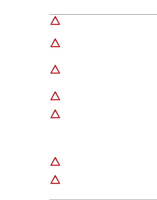
Figure 2.1 Setting Web Pages Switch (only Series B Adapter)
Unused |
Web Pages |
Switch |
Switch |
O N
1
2
Enable Web
Position
|
Disable Web |
|
Position |
|
|
SW2 Setting |
Description |
|
|
Down (OFF) position |
Disables the adapter web pages (default setting) |
|
|
Up (ON) position |
Enables the adapter web pages |
|
|
Connecting the Adapter to
the Drive |
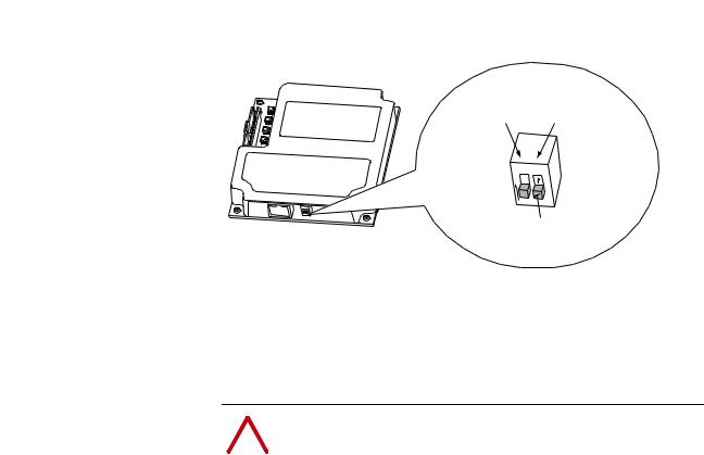
! |
ATTENTION: Risk of injury or death exists. The PowerFlex |
|
|
|
drive may contain high voltages that can cause injury or death. |
|
|
|
|
Remove power from the drive, and then verify power has been |
|
|
|
|
|
|
|
discharged before installing or removing the adapter. |
|
|
|
|
1.Remove power from the drive.
2.Use static control precautions.
3.Remove the drive cover or open the drive door.
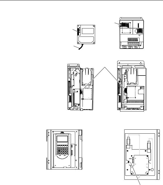
4.Connect the Internal Interface cable to the DPI port on the drive and then to the DPI connector on the adapter (see Figure 2.2).
5.Secure and ground the adapter to the drive (see Figure 2.3) by doing the following:
–On a PowerFlex 70 drive, fold the Internal Interface cable behind the adapter and mount the adapter on the drive using the four captive screws.
–On a PowerFlex 700, PowerFlex 700H or PowerFlex 700S drive, mount the adapter on the drive using the four captive screws.
Important: Tighten all screws to properly ground the adapter.
Recommended torque is 0.9 N•m (8.0 lb•in).
20-COMM-E EtherNet/IP Adapter User Manual
Publication 20COMM-UM010G-EN-P
2-4 Installing the Adapter
Figure 2.2 DPI Ports and Internal Interface Cables
20-COMM-E Adapter |
|
|
|
|
|
PowerFlex 70 - All Frames
PowerFlex 700 Frames 0 and 1 |
PowerFlex 700 Frames 2 and Larger |
PowerFlex 700S Frames 0 and 1 |
PowerFlex 700S Frames 2 through 6 |
HIM panel opens to |
|
|
allow access to DPI |
|
|
interface. To open |
|
|
panel, remove screws |
X2 |
|
on left side of HIM |
||
|
||
panel and swing open. |
X1 |
|
|
|
|
|
|
|
|
|
|
|
|
|
|
|
|
|
|
|
|
|
|
|
|
|
|
|
|
|
|
|
|
|
|
|
|
|
|
|
|
|
|
|
|
|
|
|
|
|
|
|
|
|
|
|
|
|
|
|
|
|
|
|
|
|
|
|
|
|
|
|
|
|
|
|
|
|
|
|
|
|
|
|
|
|
|
|
|
|
|
|
|
|
|
|
|
|
|
|
|
|
|
|
|
|
|
|
|
|
|
|
|
|
|
|
|
|
|
|
|
|
|
|
|
|
|
|
|
|
|
|
|
|
|
|
|
|
|
|
|
|
|
|
|
|
|
|
|
|
|
|
|
|
|
|
|
|
|
|
|
|
|
|
|
|
|
|
|
|
|
|
|
|
|
|
|
|
|
|
|
|
|
|
|
|
|
|
|
|
|
|
|
|
|
|
|
|
|
|
|
|
|
|
|
|
|
|
|
|
|
|
|
|
|
|
|
|
|
|
|
|
|
|
|
|
|
|
|
|
|
|
|
|
|
|
|
|
|
|
|
|
|
|
|
|
|
|
|
|
|
|
|
|
|
|
|
|
|
|
|
|
|
|
|
|
|
|
|
|
|
|
|
|
|
|
|
|
|
|
|
|
|
|
|
|
|
|
|
|
|
|
|
|
|
|
|
|
|
|
|
|
|
|
|
|
|
|
|
|
|
|
|
|
|
|
|
|
|
|
|
|
|
|
|
|
|
|
|
|
|
|
|
|
|
|
|
|
|
|
|
|
|
|
|
|
|
|
|
|
|
|
|
|
|
|
|
|
|
|
|
|
|
|
|
|
|
|
|
|
|
|
|
|
|
|
|
|
|
|
|
|
|
|
|
|
|
|
|
|
|
|
|
|
|
|
|
|
|
|
|
|
|
|
|
|
|
|
|
|
|
|
|
|
|
|
|
|
|
|
|
|
|
|
|
|
|
|
|
|
|
|
|
|
|
|
|
|
|
|
|
|
|
|
|
|
|
|
|
|
|
|
|
|
|
|
|
|
|
|
|
|
|
|
|
|
|
|
|
|
|
|
|
|
|
|
|
|
|
|
|
|
|
|
|
|
|
|
|
|
|
|
|
|
|
|
|
|
|
|
|
|
|
|
|
|
|
|
|
|
|
|
|
|
|
|
|
|
|
|
|
|
|
|
|
|
PowerFlex 700H Frames 9 and Larger |
|
|
|
|
|
|
|
|
|
|
|
|
||
|
|
|
|
|
|
|
|
|
|
|
|
|
|
|
|
|
|
|
|
|
PowerFlex 700S Frames 9 and Larger |
|
|
|
|
|
|
|
|
|
|||||
|
|
|
|
|
|
|
|
|
|
|
|
|
|
|
|
|
|
|
|
|
|||||||||||||||
|
Item |
Description |
|
|
|
|
|
|
|
|
|
|
|
|
|||||||||||||||||||||
|
|
|
|
|
|
|
|
|
|
|
|
|
|
|
|
|
|
|
|
|
|||||||||||||||
|
|
15.24 cm (6 in.) Internal Interface cable |
|
|
|
|
|
|
|
|
|
|
|
|
|||||||||||||||||||||
|
|
|
|
|
|
|
|
|
|
|
|
|
|
|
|
|
|
|
|
|
|||||||||||||||
|
|
DPI Connector |
|
|
|
|
|
|
|
|
|
|
|
|
|||||||||||||||||||||
|
|
|
|
|
|
|
|
|
|
|
|
|
|
|
|
|
|
|
|
|
|||||||||||||||
|
|
Ethernet cable |
|
|
|
|
|
|
|
|
|
|
|
|
|||||||||||||||||||||
|
|
|
|
|
|
|
|
|
|
|
|
|
|
|
|
|
|
|
|
|
|||||||||||||||
|
|
2.54 cm (1 in.) Internal Interface cable |
|
|
|
|
|
|
|
|
|
|
|
|
|||||||||||||||||||||
|
|
|
|
|
|
|
|
|
|
|
|
|
|
|
|
|
|
|
|
|
|
|
|
|
|
|
|
|
|
|
|
|
|
|
|
20-COMM-E EtherNet/IP Adapter User Manual
Publication 20COMM-UM010G-EN-P
Installing the Adapter |
2-5 |
|
|
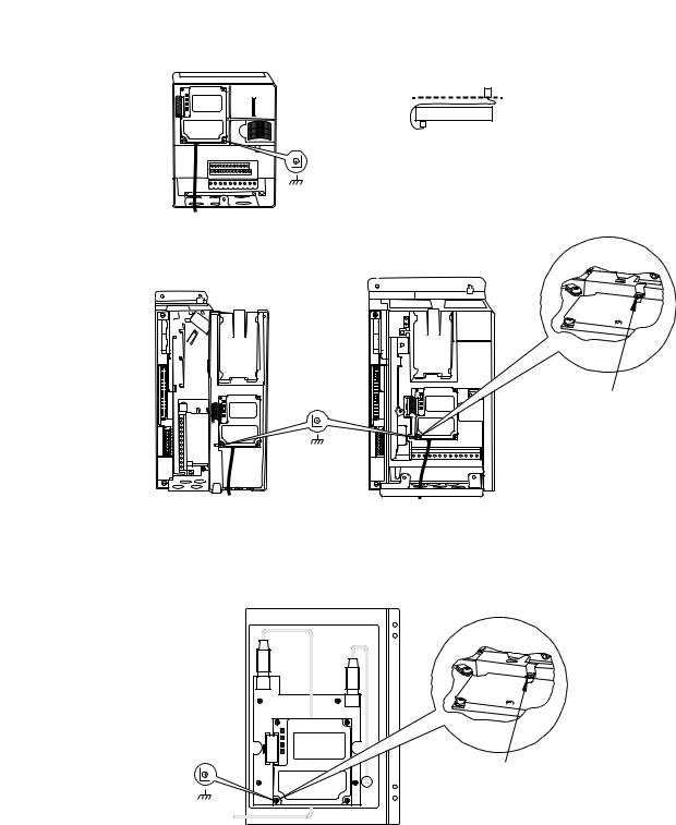
Figure 2.3 Mounting and Grounding the Adapter
0.9 N•m
(8.0 lb•in)
4 Places
PowerFlex 70 - All Frame Sizes
(Adapter mounts in drive.)
0.9 N•m
(8.0 lb•in)
4 Places
Drive
Adapter
Internal Interface Cable folded behind the adapter and in front of the drive.
Ground Tab Detail
Verify metal ground tab is bent 90° and is under the adapter before tightening screw. After tightening the screw, verify continuity exists between the head of the screw and drive ground.
PowerFlex 700 Frames 0 and 1 |
PowerFlex 700 Frames 2 and Larger |
PowerFlex 700S Frames 0 and 1 |
PowerFlex 700S Frames 2 through 6 |
(Adapter mounts on door.) |
(Adapter mounts in drive.) |
|
Ground Tab Detail |
X2
0.9 N•m
(8.0 lb•in)
4 Places
PowerFlex 700H Frames 9 and Larger PowerFlex 700S Frames 9 and Larger (Adapter mounts behind HIM panel.)
Verify metal ground tab is bent 90° and is under the adapter before tightening screw. After tightening the screw, verify continuity exists between the head of the screw and drive ground.
NOTE: When installing the adapter in a PowerFlex 750-Series drive, see the 20-750-20COMM and 20-750-20COMM-F1 Communication Carrier Cards Installation Instructions, publication 750COM-IN001, supplied with the card.
20-COMM-E EtherNet/IP Adapter User Manual
Publication 20COMM-UM010G-EN-P
2-6 Installing the Adapter
Connecting the Adapter to |
|
|
|
|
|
|
ATTENTION: Risk of injury or death exists. The PowerFlex |
||
the Network |
! |
|||
drive may contain high voltages that can cause injury or death. |
||||
|
|
|||
|
|
|
Remove power from the drive, and then verify power has been |
|
|
|
|
discharged before installing or removing the adapter. |
|
|
|
|
|
|
1.Remove power from the drive.
2.Use static control precautions.
3.Connect one end of an Ethernet cable to the network.
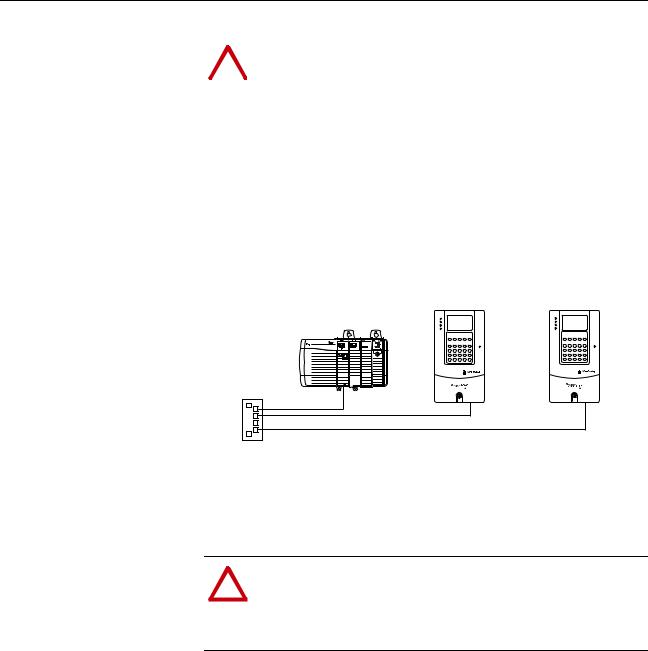
See Figure 2.4 for an example of wiring to an EtherNet/IP network.
Figure 2.4 Connecting the Ethernet Cable to the Network
Controller |
PowerFlex 7-Class Drives |
(ControlLogix shown with |
(each with a 20-COMM-E Adapter) |
1756-ENBT Bridge) |
|
Ethernet
Switch
4.Route the other end of the Ethernet cable through the bottom of the PowerFlex drive (Figure 2.3) and insert its Ethernet cable plug into the mating adapter connector.
Applying Power
ATTENTION: Risk of equipment damage, injury, or death
!exists. Unpredictable operation may occur if you fail to verify
that parameter settings are compatible with your application. Verify that settings are compatible with your application before applying power to the drive.
Install the drive cover or close the drive door, and apply power to the drive. The adapter receives its power from the connected drive. When you apply power to the adapter for the first time, its topmost ‘PORT’ status indicator should be steady green or flashing green after an initialization. If it is red, there is a problem. See Chapter 7, Troubleshooting.
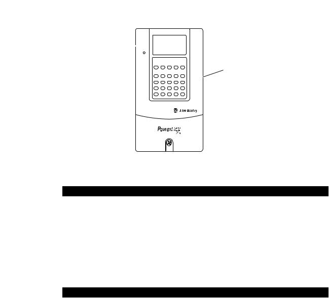
Start-Up Status Indications
Status indicators for the drive and communication adapter can be viewed on the front of the drive (Figure 2.5) after power has been applied. Possible start-up status indications are shown in Table 2.A.
20-COMM-E EtherNet/IP Adapter User Manual
Publication 20COMM-UM010G-EN-P
Installing the Adapter |
2-7 |
|
|
Figure 2.5 Drive and Adapter Status Indicators (location on drive may vary)
PORT
MOD
 NET A
NET A
NET B
 STS
STS
Table 2.A Drive and Adapter Start-Up Status Indications
Item |
Name |
Color |
State |
|
Description |
|
|
|
|
|
|
|
|
|
|
|
Drive STS Indicator |
|
|
|
|
|
|
|
STS |
Green |
Flashing |
|
Drive ready but not running, and no faults are present. |
|
(Status) |
|
|
|
|
|
|
Steady |
|
Drive running, no faults are present. |
|
|
|
|
|
||
|
|
|
|
|
|
|
|
Yellow |
Flashing, |
|
An inhibit condition exists – the drive cannot be started. Check drive |
|
|
|
drive stopped |
|
Parameter 214 - [Start Inhibits]. |
|
|
|
|
|
|
|
|
|
Flashing, |
|
An intermittent type 1 alarm condition is occurring. Check drive |
|
|
|
drive running |
|
Parameter 211 - [Drive Alarm 1]. |
|
|
|
|
|
|
|
|
|
Steady, |
|
A continuous type 1 alarm condition exists. Check drive Parameter |
|
|
|
drive running |
|
211 - [Drive Alarm 1]. |
|
|
|
|
|
|
|
|
Red |
Flashing |
|
A fault has occurred. |
|
|
|
|
|
|
|
|
|
Steady |
|
A non-resettable fault has occurred. |
|
|
|
|
|
|
|
|
|
|
Adapter Status Indicators |
|
|
|
|
|
|
|
|
PORT |
Green |
Flashing |
|
Normal operation. The adapter is establishing an I/O connection to |
|
|
|
|
|
the drive. It will turn steady green or red. |
|
|
|
|
|
|
|
|
|
Steady |
|
Normal operation. The adapter is properly connected and |
|
|
|
|
|
communicating with the drive. |
|
|
|
|
|
|
|
MOD |
Green |
Flashing |
|
Normal operation. The adapter is operating but is not transferring I/O |
|
|
|
|
|
data to a controller. |
|
|
|
|
|
|
|
|
|
Steady |
|
Normal operation. The adapter is operating and transferring I/O data |
|
|
|
|
|
to a controller. |
|
|
|
|
|
|
|
NET A |
— |
Off |
|
Normal operation. BOOTP is enabled or a valid IP address is not set. |
|
|
|
|
|
|
|
|
Green |
Flashing |
|
Normal operation. BOOTP is disabled, the adapter is properly |
|
|
|
|
|
connected, has an IP address, and is connected to an EtherNet/IP |
|
|
|
|
|
network but does not have an I/O connection. |
|
|
|
|
|
|
|
|
|
Steady |
|
Normal operation. The adapter is properly connected and |
|
|
|
|
|
communicating on the network to a controller. |
|
|
|
|
|
|
|
NET B |
— |
Off |
|
Normal operation. The adapter is properly connected but is idle. |
|
|
|
|
|
|
|
|
Green |
Flashing |
|
Normal operation. The adapter is properly connected, BOOTP is |
|
|
|
|
|
enabled, and the adapter is transmitting data packets on the network. |
|
|
|
|
|
|
For more details on status indicator operation, see page 7-2 and page 7-3.
20-COMM-E EtherNet/IP Adapter User Manual
Publication 20COMM-UM010G-EN-P

2-8 Installing the Adapter
Configuring and Verifying Key Drive Parameters
The PowerFlex 7-Class drive can be separately configured for the control and Reference functions in various combinations. For example, you could set the drive to have its control come from a peripheral or terminal block with the Reference coming from the network. Or you could set the drive to have its control come from the network with the Reference coming from another peripheral or terminal block. Or you could set the drive to have both its control and Reference come from the network.
The following steps in this section assume that the drive will receive the
Logic Command and Reference from the network.
1.Use drive Parameter 090 - [Speed Ref A Sel] to set the drive speed Reference to ‘22’ (DPI Port 5).
2.If hard-wired discrete digital inputs are not used to control the drive, verify that unused digital input drive Parameters 361 - [Dig In1 Sel] and 362 - [Dig In2 Sel] are set to ‘0’ (Not Used).
3.Verify that drive Parameter 213 - [Speed Ref Source] is reporting that the source of the Reference to the drive is ‘22’ (DPI Port 5).
This ensures that any Reference commanded from the network can be monitored by using drive Parameter 002 - [Commanded Speed]. If a problem occurs, this verification step provides the diagnostic capability to determine whether the drive/adapter or the network is the cause.
TIP: For PowerFlex 750-Series drives, use drive Parameter 545 - [Speed Ref A Sel] to set the drive speed Reference:
a.Set the Port field to ‘0 - PowerFlex 75x’.
b.Set the Parameter field to point to the port (slot) in which the 20-COMM-E adapter/20-750-20COMM Communication Carrier Card are installed (for this example, ‘876 - Port 6 Reference’).
The number ‘876’ in the Parameter field of the example is the parameter in the drive that points to the port.
Commissioning the Adapter To commission the adapter, you must set a unique IP address on the network. See the Glossary for details about IP addresses. After installing the adapter and applying power, you can set the IP address by using a BOOTP server or adapter parameters. See Using Parameters to Set the IP Address, Subnet Mask, and Gateway Address on page 3-5 for details.
By default, the adapter is configured so that you must set the IP address using a BOOTP server. To use adapter parameters, you must disable the BOOTP feature. For details, see Disable the BOOTP Feature on page 3-5.
Important: New settings for some adapter parameters (for example,
Parameters 04 - [IP Addr Cfg 1] through 07 - [IP Addr Cfg 4]) are recognized only when power is applied to the adapter or it is reset. After you change parameter settings, cycle power or reset the adapter.
20-COMM-E EtherNet/IP Adapter User Manual
Publication 20COMM-UM010G-EN-P

Chapter 3
Configuring the Adapter
This chapter provides instructions and information for setting the parameters in the adapter.
Topic |
Page |
|
|
Configuration Tools |
3-1 |
|
|
Using the PowerFlex 7-Class HIM to Access Parameters |
3-2 |
|
|
Using BOOTP Server to Set the IP Address, Subnet Mask, and Gateway Address |
3-3 |
|
|
Using Parameters to Set the IP Address, Subnet Mask, and Gateway Address |
3-5 |
|
|
Setting the Data Rate |
3-7 |
|
|
Setting the I/O Configuration |
3-7 |
|
|
Selecting Master-Slave or Peer-to-Peer Hierarchy |
3-8 |
|
|
Setting the Reference Adjustment |
3-13 |
|
|
Setting a Fault Action |
3-14 |
|
|
Setting Web Access Control |
3-15 |
|
|
Resetting the Adapter |
3-16 |
|
|
Viewing the Adapter Status Using Parameters |
3-17 |
|
|
Updating the Adapter Firmware |
3-17 |
|
|
For a list of parameters, see Appendix B, Adapter Parameters. For definitions of terms in this chapter, see the Glossary.
Configuration Tools |
The adapter stores parameters and other information in its own nonvolatile |
|
|
storage (NVS) memory. You must, therefore, access the adapter to view and |
|
|
edit its parameters. The following tools can be used to access the adapter |
|
|
parameters. |
|
|
|
|
|
Tool |
See |
|
|
|
|
PowerFlex 7-Class HIM |
page 3-2 |
|
|
|
|
BOOTP Server |
page 3-3 |
|
|
|
|
Connected Components Workbench |
http://www.ab.com/support/abdrives/webupdate/ |
|
software, version 1.02 or later |
software.html, or online help (installed with the software) |
|
|
|
|
DriveExplorer software, |
http://www.ab.com/drives/driveexplorer, or online help |
|
version 2.01 or later |
(installed with the software) |
|
|
|
|
DriveExecutive software, |
http://www.ab.com/drives/drivetools, or online help |
|
version 3.01 or later |
(installed with the software) |
|
|
|
20-COMM-E EtherNet/IP Adapter User Manual
Publication 20COMM-UM010G-EN-P
3-2 Configuring the Adapter
Usingthe PowerFlex7-Class HIM to Access Parameters
If your drive has either an LED or LCD HIM (Human Interface Module), it can be used to access parameters in the adapter as shown below. We recommend that you read through the steps for your HIM before performing the sequence. For additional information, see the drive documentation or the PowerFlex 7-Class HIM Quick Reference, publication 20HIM-QR001.
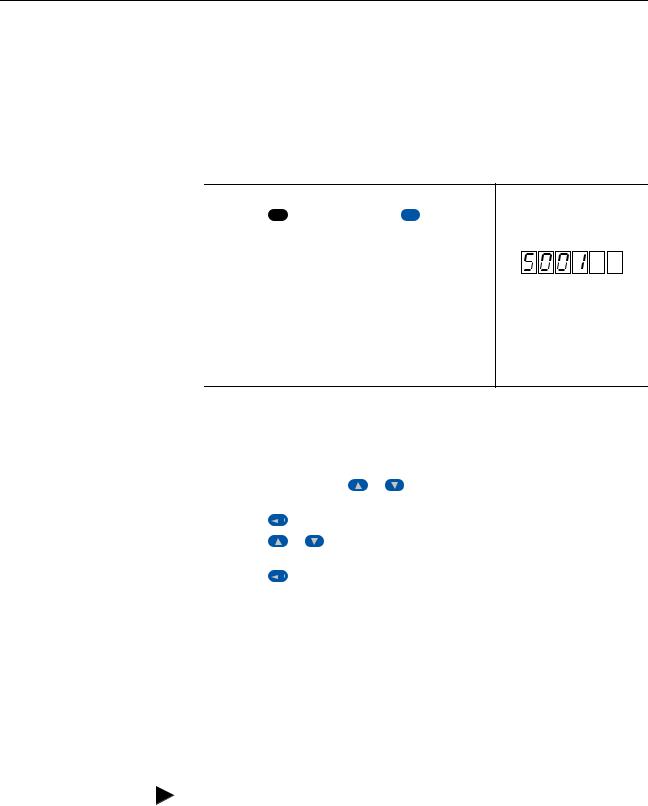
Using an LED HIM
Step |
Example Screens |
|
|
1. Press the ALT key and then the Device Sel |
(Sel) key to |
display the Device Screen. |
|
2. Press the  or
or  key to scroll to the adapter.
Letters represent files in the drive, and numbers represent ports. The adapter is usually connected to port 5.
3.Press the  (Enter) key to enter your selection.
A parameter database is constructed, and then the first parameter is displayed.
4.Edit the parameters using the same techniques that you use to edit drive parameters.
Using an LCD HIM
Step |
|
|
|
|
Example Screens |
|
|
|
|||||
|
|
|
|
|
|
|
|
|
|
|
|
||
1. |
In the main menu, press the |
or |
key to scroll to |
|
|
|
|
|
|
||||
|
Device Select. |
|
|
|
|
|
F-> |
Stopped |
|
Auto |
|
||
2. |
Press the |
|
|
(Enter) key to enter your selection. |
|
|
0.00 |
Hz |
|
||||
|
|
|
Main Menu: |
|
|
|
|||||||
3. |
Press the |
or |
key to scroll to the adapter |
|
|
|
|
||||||
|
Diagnostics |
|
|
|
|||||||||
|
(20-COMM-E). |
|
|
|
|
|
Parameter |
|
|
|
|||
4. |
Press the |
|
|
(Enter) key to select the adapter. |
|
Device Select |
|
|
|
||||
|
|
|
|
|
|
|
|
||||||
|
A parameter database is constructed, and then the main |
|
|
|
|
|
|
||||||
|
|
Port 5 Device |
|
|
|
||||||||
|
menu for the adapter is displayed. |
|
|
|
|
|
|
||||||
|
|
|
|
20-COMM-E |
|
|
|
||||||
5. |
Edit the parameters using the same techniques that you use |
|
|
|
|
||||||||
|
Main Menu: |
|
|
|
|||||||||
|
to edit drive parameters. |
|
|
|
|
|
|
||||||
|
|
|
|
Diagnostics |
|
|
|
||||||
|
|
|
|
|
|
|
|
|
|
|
|
||
|
|
|
|
|
|
|
|
|
Parameter |
|
|
|
|
|
|
|
|
|
|
|
|
|
Device Select |
|
|
|
|
|
|
|
|
|
|
|
|
|
|
|
|
|
|
|
|
|
|
|
|
|
|
|
|
|
|
|
|
NOTE: All configuration procedures throughout this chapter use the PowerFlex 7-Class LCD HIM to access parameters in the adapter and show example LCD HIM screens.
TIP: When using a PowerFlex 20-HIM-A6 or 20-HIM-C6S HIM, see its User Manual, publication 20-HIM-UM001.
20-COMM-E EtherNet/IP Adapter User Manual
Publication 20COMM-UM010G-EN-P
Loading...