


ArmorStart® Distributed Motor
Controller
USER MANUAL
Bulletin 280G/281G, 284G
3
Important User Information Because of the variety of uses for the products described in this publication, those responsible for the application and use of this control equipment must
satisfy themselves that all necessary steps have been taken to assure that each application and use meets all performance and safety requirements, including any applicable laws, regulations, codes and standards.
The illustrations, charts, sample programs and layout examples shown in this guide are intended solely for purposes of example. Since there are many variables and requirements associated with any particular installation, Rockwell Automation does not assume responsibility or liability (to include intellectual property liability) for actual use based upon the examples shown in this publication.
Rockwell Automation publication SGI-1.1, Safety Guidelines for the Application, Installation and Maintenance of Solid-State Control (available from your local Allen-Bradley sales office), describes some important differences between solid-state equipment and electromechanical devices that should be taken into consideration when applying products such as those described in this publication.
Reproduction of the contents of this copyrighted publication, in whole or part, without written permission of Rockwell Automation, is prohibited.
Throughout this manual we use notes to make you aware of safety considerations:
ATTENTION
Identifies information about practices or circumstances that can lead to personal injury or death, property damage
!or economic loss
Attention statements help you to:
•identify a hazard
•avoid a hazard
•recognize the consequences
IMPORTANT |
Identifies information that is critical for successful |
|
application and understanding of the product. |
||
|
Trademark List
ArmorStart and ControlLogix are registered trademarks of Rockwell Automation, Inc.
ArmorConnect, DeviceLogix, PLC, RSNetWorx, RSLogix 5000, and SLC are trademarks of Rockwell Automation, Inc. DeviceNet and the DeviceNet logo are trademarks of the Open Device Vendors Association (ODVA). ControlNet is a trademark of ControlNet International, LTD.

4
European Communities (EC)
Directive Compliance
If this product has the CE mark it is approved for installation within the European Union and EEA regions. It has been designed and tested to meet the following directives.
Low Voltage and EMC Directives
This product is tested to meet Council Directive 73/23/EEC Low Voltage and 89/336/EEC and Council Directive 89/336/EC Electromagnetic Compatibility (EMC) by applying the following standard(s):
•Bulletin 280/281: EN 60947-4-1 — Low-voltage switchgear and controlgear — Part 4-1:Contactors and motor-starters — Electromechanical contactors and motor-starters.
•Bulletin 283: EN 60947-4-2 — Low-voltage switchgear and controlgear — Part 4-2: AC semiconductor motor controllers and starters.
•Bulletin 284: EN 61800-3 — Adjustable speed electronic power drive systems — Part 3: EMC product standard including specific test methods.
This product is intended for use in an industrial environment.

Table of Contents |
i |
Chapter 1
Product Overview
Chapter 2
Installation and Wiring
Table of Contents
Introduction .................................................................................... |
1-1 |
Description ..................................................................................... |
1-1 |
Safety ArmorStart............................................................................ |
1-1 |
Operation ....................................................................................... |
1-2 |
Mode of Operation .......................................................................... |
1-2 |
Bulletin 280G/281G — Full-Voltage Start ................................ |
1-2 |
Bulletin 284G — Sensorless Vector Control.............................. |
1-2 |
Description of Features .................................................................. |
1-3 |
Overload Protection ................................................................. |
1-3 |
LED Status Indication .............................................................. |
1-5 |
Fault Diagnostics ..................................................................... |
1-5 |
Inputs ...................................................................................... |
1-6 |
Gland Plate Entrance ............................................................... |
1-6 |
ArmorStart with DeviceNet Network Capabilities ...................... |
1-6 |
DeviceLogix™ ........................................................................ |
1-6 |
Peer to Peer Communications (ZIP) .......................................... |
1-6 |
EMI Filter.................................................................................. |
1-6 |
Dynamic Brake Resistor ........................................................... |
1-7 |
Control Brake Contactor .......................................................... |
1-7 |
Receiving ....................................................................................... |
2-1 |
Unpacking ...................................................................................... |
2-1 |
Inspecting ...................................................................................... |
2-1 |
Storing ........................................................................................... |
2-1 |
General Precautions ....................................................................... |
2-2 |
Precautions for Bulletin 280G/281G Applications ............................. |
2-2 |
Precautions for Bulletin 284G Applications ...................................... |
2-2 |
Dimensions .................................................................................... |
2-4 |
Bulletin 280G/281G .................................................................. |
2-4 |
Bulletin 284G ........................................................................... |
2-6 |
Bulletin 1000............................................................................ |
2-8 |
Wiring .......................................................................................... |
2-13 |
Power, Control, Safety Monitor Inputs, and |
|
Ground Wiring ...................................................................... |
2-13 |
Terminal Designations .................................................................. |
2-14 |
Dimensions for Safety Products..................................................... |
2-15 |
Bulletin 280G Safety Product .................................................. |
2-15 |
Bulletin 281G Safety Product .................................................. |
2-16 |
Bulletin 284G Safety Product .................................................. |
2-17 |
Bulletin 1000 Safety Product .................................................. |
2-19 |
Safety Terminal Designations ....................................................... |
2-26 |
ArmorConnect Power Media ......................................................... |
2-29 |
Description ............................................................................ |
2-29 |
ArmorStart with ArmorConnect Connectivity .......................... |
2-30 |
Terminal Designations............................................................ |
2-30 |
ArmorStart Safety with ArmorConnect Connectivity ............... |
2-31 |
Terminal Designations............................................................ |
2-31 |
ArmorConnect Cable Ratings ................................................. |
2-31 |
Branch Circuit Protection Requirements for |
|
ArmorConnect Three-Phase Power Media ............................. |
2-32 |
Group Motor Installations for USA and Canada Markets ................ |
2-32 |

ii |
Table of Contents |
|
Wiring and Workmanship Guidelines ............................................ |
2-32 |
|
DeviceNet Network Installation ..................................................... |
2-33 |
|
Other DeviceNet System Design Considerations .................... |
2-34 |
|
Electromagnetic Compatibility (EMC) ............................................ |
2-35 |
|
General Notes (Bulletin 284G only) ........................................ |
2-35 |
|
Grounding ............................................................................. |
2-35 |
|
Wiring ................................................................................... |
2-35 |
Chapter 3 |
Introduction .................................................................................... |
3-1 |
Bulletin 280G/281G |
Parameter Programming ......................................................... |
3-1 |
Programmable Parameters |
Parameter Group Listing ................................................................. |
3-2 |
|
DeviceLogix™ Group ..................................................................... |
3-2 |
|
DeviceNet Group ............................................................................ |
3-7 |
|
Starter Protection Group ............................................................... |
3-10 |
|
User I/O ........................................................................................ |
3-14 |
|
Misc. Group ................................................................................. |
3-14 |
|
ZIP Parameters ............................................................................ |
3-16 |
|
Starter Display ............................................................................. |
3-23 |
|
Starter Setup ................................................................................ |
3-24 |
Chapter 4
Bulletin 284G Programmable Parameters for Sensorless Vector Controllers
Introduction .................................................................................... |
4-1 |
Parameter Programming ......................................................... |
4-1 |
Parameter Group Listing ................................................................. |
4-2 |
DeviceLogix™ Group ..................................................................... |
4-3 |
DeviceNet Group ............................................................................ |
4-8 |
Starter Protection Group ............................................................... |
4-12 |
User I/O ........................................................................................ |
4-15 |
Miscellaneous Group .................................................................... |
4-16 |
Drive DeviceNet Group .................................................................. |
4-18 |
Display Group................................................................................ |
4-20 |
Basic Program Group .................................................................... |
4-25 |
Advanced Program Group.............................................................. |
4-28 |
Clear Type 1 Fault and Restart ...................................................... |
4-42 |
Clear an Overvoltage, Undervoltage, or Heatsink OvrTmp Fault |
|
without Restarting the Drive .......................................................... |
4-42 |
How Step Logic Works ................................................................. |
4-55 |
Step Logic Settings ....................................................................... |
4-55 |
Chapter 5
DeviceNet™ Commissioning
Establishing a DeviceNet Node Address .......................................... |
5-1 |
Node Commissioning using Hardware ............................................ |
5-1 |
Node Commissioning using Software ............................................. |
5-2 |
Building and Registering an EDS File .............................................. |
5-3 |

Table of Contents |
iii |
Chapter 6
Explicit Messaging on DeviceNet™
Chapter 7
Using DeviceLogix™
Chapter 8
ArmorStart® ZIP Configuration
Using the Node Commissioning Tool Inside RSNetWorx |
|
for DeviceNet ................................................................................. |
5-5 |
System Configuration ................................................................... |
5-6 |
Using Automap feature with default Input and Output (I/O) |
|
Assemblies (Bulletin 280G/281G).................................................... |
5-7 |
Default Input and Output (I/O) Assembly Formats |
|
(Bulletin 280G/281G) ...................................................................... |
5-7 |
Setting the Motor FLA and Overload Trip Class |
|
(Bulletin 280G/281G) ...................................................................... |
5-8 |
Using Automap feature with default Input and Output (I/O) |
|
Assemblies (Bulletin 284G) ............................................................. |
5-9 |
Default Input and Output (I/O) Assembly Formats (Bulletin 284G) .... |
5-9 |
Setting the Motor FLA (Bulletin 284G) ........................................... |
5-10 |
193-DCNT Product Overview ........................................................ |
5-11 |
User Manual .......................................................................... |
5-11 |
Bill of Material ....................................................................... |
5-11 |
Accessories ........................................................................... |
5-11 |
Tools Menu............................................................................ |
5-12 |
Node Comissioning ................................................................ |
5-12 |
Logic Controller Application Example with Explicit |
|
Messaging ..................................................................................... |
6-1 |
Programming the 1747-SLC .......................................................... |
6-2 |
I/O Mapping ............................................................................ |
6-2 |
Explicit Messaging with SLC .......................................................... |
6-3 |
Setting up the Data File ................................................................. |
6-4 |
Sequence of Events ....................................................................... |
6-5 |
Programming the 1756-ControlLogix ............................................. |
6-8 |
I/O Mapping ............................................................................ |
6-8 |
Explicit Messaging with ControlLogix ............................................. |
6-9 |
Setting Up the MSG Instruction ...................................................... |
6-9 |
DeviceLogix Programming ............................................................. |
7-1 |
DeviceLogix Programming Example ............................................... |
7-2 |
ArmorStart Fault Bit, Status Bit, Outputs and Produced Network Bits in |
|
the DeviceLogix Ladder Editor ....................................................... |
7-5 |
Overview ....................................................................................... |
8-1 |
ZIP Parameter Overview ................................................................ |
8-1 |
Data Production ............................................................................. |
8-3 |
Data Consumption ......................................................................... |
8-3 |
Mapping Consumed Data to the DeviceLogix Data Table. ............... |
8-3 |
Finding ZIP bits in Device Logix Editor........................................... |
8-12 |

iv |
Table of Contents |
Chapter 9
Diagnostics
Chapter 10
Troubleshooting
Appendix A
Specifications
Overview ........................................................................................ |
9-1 |
Protection Programming .......................................................... |
9-1 |
Fault Display .................................................................................. |
9-1 |
Clear Fault ..................................................................................... |
9-2 |
Fault Codes .................................................................................... |
9-2 |
Fault Definitions ............................................................................. |
9-3 |
Short Circuit ............................................................................ |
9-3 |
Overload Trip ........................................................................... |
9-3 |
Phase Loss .............................................................................. |
9-3 |
Phase Short.............................................................................. |
9-3 |
Ground Fault ............................................................................ |
9-3 |
Stall ......................................................................................... |
9-3 |
Control Power .......................................................................... |
9-3 |
I/O Fault .................................................................................. |
9-3 |
Over Temperature ................................................................... |
9-3 |
Phase Imbalance ..................................................................... |
9-3 |
Over Current............................................................................. |
9-4 |
DeviceNet™ Power Loss ......................................................... |
9-4 |
Internal Communication Fault ................................................... |
9-4 |
DC Bus Fault ............................................................................ |
9-4 |
EEPROM Fault ......................................................................... |
9-4 |
Hardware Fault ........................................................................ |
9-4 |
Restart Retries ......................................................................... |
9-4 |
Miscellaneous Faults ................................................................ |
9-4 |
Introduction .................................................................................. |
10-1 |
Bulletin 280G/281G Troubleshooting ............................................. |
10-2 |
Bulletin 284G Troubleshooting....................................................... |
10-5 |
Fault Definitions ..................................................................... |
10-5 |
Operation and Troubleshooting of the DB1Dynamic Brake.... |
10-7 |
Internal Drive Faults ............................................................. |
10-10 |
DeviceNet Troubleshooting Procedures ...................................... |
10-14 |
Control Module Replacement (Bulletin 280G/281G) ..................... |
10-15 |
Control Module Replacement (Bulletin 284G)............................... |
10-16 |
Base Module Replacement (Bulletin 280G/281G)......................... |
10-17 |
Base Module Replacement (Bulletin 284G) .................................. |
10-19 |
Bulletin 280G/281G Specifications .................................................. |
A-1 |
Bulletin 284G Specifications............................................................ |
A-6 |
ArmorConnect™ Three-Phase Power Media ................................ |
A-11 |
Patchcords ............................................................................ |
A-11 |
Power Tees & Reducer .......................................................... |
A-12 |
Power Receptacles ................................................................ |
A-13 |
Appendix B |
Electronic Data Sheets ................................................................... |
B-1 |
Bulletin 280G/281G CIP Information |
DOL Type Product Codes and Name Strings ................................... |
B-1 |
|
DOL Reversing Type Product Codes and Name String ..................... |
B-2 |
|
DeviceNet Objects .......................................................................... |
B-2 |

Table of Contents |
v |
Appendix C
Bulletin 284G CIP Information
Identity Object — CLASS CODE 0x0001 ......................................... |
B-3 |
Identity Objects .............................................................................. |
B-3 |
Message Router — CLASS CODE 0x0002 ...................................... |
B-3 |
DeviceNet Object — CLASS CODE 0x0003 ..................................... |
B-4 |
Assembly Object — CLASS CODE 0x0004 ..................................... |
B-5 |
Custom Parameter Based |
|
“Word-wise” I/O Assemblies .......................................................... |
B-5 |
“Word-wise” Bit-Packed Assemblies .............................................. |
B-6 |
Standard Distributed Motor Controller I/O Assemblies ..................... |
B-7 |
Standard Distributed Motor Controller Output |
|
(Consumed) Assemblies .......................................................... |
B-7 |
Standard Distributed Motor Controller Input |
|
(Produced) Assemblies ............................................................ |
B-8 |
Connection Object — CLASS CODE 0x0005 ................................. |
B-10 |
Discrete Input Point Object — CLASS CODE 0x0008 ................... |
B-14 |
Discrete Output Point Object — CLASS CODE 0x0009 .................. |
B-15 |
Discrete Output Point Object Special Requirements ...................... |
B-16 |
DOP Instances 1 and 2 Special Behavior ............................... |
B-16 |
Parameter Object — CLASS CODE 0x000F .................................. |
B-18 |
Parameter Group Object — CLASS CODE 0x0010 ........................ |
B-19 |
Discrete Input Group Object — CLASS CODE 0x001D .................. |
B-20 |
Discrete Output Group Object — CLASS CODE 0x001E ................ |
B-21 |
Control Supervisor Object -CLASS CODE 0x0029 .......................... |
B-22 |
Acknowledge Handler Object — CLASS CODE 0x002b ................. |
B-23 |
Overload Object — CLASS CODE 0x002c ..................................... |
B-24 |
DeviceNet Interface Object -CLASS CODE 0x00B4 ........................ |
B-25 |
Electronic Data Sheets ................................................................... |
C-1 |
VFD Type Product Codes and Name Strings .................................... |
C-1 |
DeviceNet Objects .......................................................................... |
C-2 |
Identity Object — CLASS CODE 0x0001 ......................................... |
C-2 |
Identity Objects .............................................................................. |
C-3 |
Message Router — CLASS CODE 0x0002 ...................................... |
C-3 |
DeviceNet Object — CLASS CODE 0x0003 ..................................... |
C-4 |
Assembly Object — CLASS CODE 0x0004 ..................................... |
C-5 |
Custom Parameter Based |
|
“Word-wise” I/O Assemblies .......................................................... |
C-6 |
“Word-wise” Bit-Packed Assemblies .............................................. |
C-6 |
Standard Distributed Motor Controller I/O Assemblies ..................... |
C-8 |
Standard Distributed Motor Controller Output |
|
(Consumed) Assemblies .......................................................... |
C-8 |
Standard Distributed Motor Controller Input |
|
(Produced) Assemblies ............................................................ |
C-9 |
Inverter Type Distributed Motor Controller Input |
|
(Produced) Assemblies ........................................................... |
C-10 |
PowerFlex Native Assemblies ................................................. |
C-11 |
Connection Object — CLASS CODE 0x0005 ................................. |
C-13 |
Discrete Input Point Object — CLASS CODE 0x0008 ................... |
C-18 |
Discrete Output Point Object — CLASS CODE 0x0009 .................. |
C-19 |

vi |
Table of Contents |
Appendix D
Group Motor Installations
Appendix E
Accessories
Appendix F
Safety I/O Module and TÜV
Requirements
Appendix G
Renewal Parts
Appendix H
PID Setup
Discrete Output Point Object Special Requirements ...................... |
C-20 |
DOP Instances 3 and 4 Special Behavior ............................... |
C-20 |
DOP Instances 1, 2, 9, and 10 Special Behavior .................... |
C-22 |
Parameter Object — CLASS CODE 0x000F .................................. |
C-24 |
Parameter Group Object — CLASS CODE 0x0010 ........................ |
C-25 |
Discrete Input Group Object — CLASS CODE 0x001D .................. |
C-26 |
Discrete Output Group Object — CLASS CODE 0x001E ................ |
C-27 |
Control Supervisor Object -CLASS CODE 0x0029 .......................... |
C-28 |
Acknowledge Handler Object — CLASS CODE 0x002b ................. |
C-29 |
DeviceNet Interface Object -CLASS CODE 0x00B4 ........................ |
C-30 |
Application of ArmorStart® Controllers in Group Installation ........... |
D-1 |
IP67 Dynamic Brake Resistor .......................................................... |
E-3 |
ArmorStart Safety-Related Parts...................................................... |
F-1 |
ArmorBlock Guard I/O Modules ....................................................... |
F-2 |
Specifications .......................................................................... |
F-2 |
ArmorBlock Guard I/O Recommended Compatible |
|
Cables and Connectors.................................................................... |
F-3 |
Safety-Related Specifications.......................................................... |
F-6 |
Maintenance and Internal Part Replacement.................................... |
F-6 |
Troubleshooting .............................................................................. |
F-7 |
Renewal Parts................................................................................. |
G-1 |
Exclusive Control............................................................................. |
H-1 |
Trim Control .................................................................................... |
H-2 |
PID Reference and Feedback........................................................... |
H-3 |
PID Deadband ................................................................................. |
H-3 |
PID Preload ..................................................................................... |
H-4 |
PID Limits ....................................................................................... |
H-4 |
PID Gains ........................................................................................ |
H-4 |
Guidelines For Adjusting PID Gains .................................................. |
H-5 |
Appendix I |
Step Logic Using Timed Steps .......................................................... |
I-2 |
Step Logic, Basic Logic and Timer/ |
Step Logic Using Basic Logic Functions............................................ |
I-3 |
Counter Functions |
Timer Function................................................................................. |
I-4 |
|
Counter Function.............................................................................. |
I-4 |
|
Step Logic Parameters ..................................................................... |
I-5 |
Chapter 1
Product Overview
Introduction
Description
Safety ArmorStart
This chapter provides a brief overview of the features and functionality of the Bulletin 280G/281G and 284G ArmorStart® Distributed Motor Controllers.
The ArmorStart Distributed Motor Controllers are integrated, preengineered, starters with Bulletin 280G/281G for full-voltage and reversing applications and Bulletin 284G for variable frequency AC drives applications. The ArmorStart offers a robust IP67/NEMA Type 4 enclosure design, which is suitable for water wash down environments.
The modular “plug and play” design offers simplicity in wiring the installation. The quick disconnects for the I/O, communications, and motor connections reduce the wiring time and eliminate wiring errors. The ArmorStart offers as standard, six DC inputs to be used with sensors for monitoring and controlling the application process. The ArmorStart’s LED status indication and built-in diagnostics capabilities allow ease of maintenance and troubleshooting.
The ArmorStart Distributed Motor Controller offers short circuit protection per UL508 and IEC 60947. The ArmorStart is rated for local-disconnect service by incorporating the Bulletin 140 Motor Protector as the local-disconnect, eliminating the need for additional components. The ArmorStart Distributed Motor Controllers are suitable for group motor installations.
The safety version of the ArmorStart provides a safety solution integrated into DeviceNet Safety installations. The Bulletin 280/281/ 284 Safety ArmorStart achieves Category 4 functionality by using redundant contactors. The Safety ArmorStart offers a quick connects via the gland plate to the 1732DS-IB8XOBV4 safety I/O module. The Bulletin 1732DS Safety I/O inputs will monitor the status of the safety rated contactors inside the ArmorStart. The Bulletin 1732DS Safety I/O outputs to provide 24V DC power for control power to the ArmorStart.
Note: The Bulletin 280/281/284 Safety ArmorStart is suitable for safety applications up to Safety Category 4PL e (TÜV assessment per ISO 13849-1:2008). TÜV compliance letter is available upon request.
Note: For additional information regarding the 1732DS-IB8XOBV4 safety I/O module, see publication 1791DS-UM001*-EN-P.

1-2 |
Product Overview |
|
|
|
|
Operation |
|
The ArmorStart Distributed Motor Controllers can operate three- |
|
|
phase squirrel-cage induction motors as follows: |
|
|
Bulletin 280G/281G: up to 10 Hp (7.5 kW) @ 460VAC, 50/60 Hz. |
|
|
Bulletin 284G: up to 5 Hp (3.0 kW) @ 460V AC. |
|
|
Bulletin 1000: 7.5 Hp (5.5 kW), 10 Hp (7.5 kW) and 15 Hp (11 kW) |
|
|
@ 460VAC, 50/60 Hz. |
|
|
The ArmorStart Distributed Motor Controller will accept a control |
|
|
power input of 120VAC. |
Mode of Operation |
Bulletin 280G/281G |
|
|
|
Full-Voltage Start |
This method is used in applications requiring across-the-line starting, in which full inrush current and locked-rotor torque are realized. The ArmorStart Bulletin 280G offers full-voltage starting and the Bulletin 281G offers full-voltage starting for reversing applications.
100%
Percent
Voltage
Time (seconds)
Bulletin 284G
Sensorless Vector Control
•Sensorless Vector Control provides exceptional speed regulation and very high levels of torque across the entire speed range of the drive
•The Autotune feature allows the Bulletin 284G ArmorStart Distributed Motor Controller to adapt to individual motor characteristics.
•To select this method of operation, select V for the Mode of Operation listed in the catalog structure. See
Publication 280-SG001*.

Product Overview |
1-3 |
|
|
Description of Features |
Overload Protection |
The ArmorStart Distributed Motor Controller incorporates, as standard, electronic motor overload protection. This overload
protection is accomplished electronically with an I2t algorithm. The ArmorStart’s overload protection is programmable via the communication network, providing the user with flexibility.
The Bulletin 280G/281G overload trip class can be selected for class 10, 15, 20 protection. Ambient insensitivity is inherent in the electronic design of the overload.
Figure 1.1 Overload Trip Curves
|
|
Class 10 Overload Curves |
|
|||||
|
|
|
Class 10 |
|
|
|
||
|
10000 |
|
|
|
|
|
|
|
(sec) |
1000 |
|
|
|
|
|
|
|
Time |
|
|
|
|
|
|
|
|
|
|
|
|
|
|
|
|
|
Trip |
100 |
|
|
|
|
|
|
Cold |
|
|
|
|
|
|
Hot |
||
Approximate |
|
|
|
|
|
|
|
|
10 |
|
|
|
|
|
|
|
|
|
|
|
|
|
|
|
|
|
|
1 |
|
|
|
|
|
|
|
|
0 |
100 |
200 |
300 |
400 |
500 |
600 |
700 |
|
|
|
Multiples% of Full Load Current |
|
||||
|
|
Class 15 Overload Curves |
|
|||||
|
|
|
|
Class 15 |
|
|
|
|
|
10000 |
|
|
|
|
|
|
|
Time (sec) |
100 |
|
|
|
|
|
|
|
Trip |
|
|
|
|
|
|
Cold |
|
|
|
|
|
|
|
|
|
|
Approximate |
|
|
|
|
|
|
|
Hot |
|
|
|
|
|
|
|
|
|
|
1 |
|
|
|
|
|
|
|
|
0 |
100 |
200 |
300 |
400 |
500 |
600 |
700 |
|
|
Multiples%forof Full Load Current |
|
|||||
|
|
Class 20 Overload Curves |
|
|||||
|
|
|
|
Class 20 |
|
|
|
|
|
10000 |
|
|
|
|
|
|
|
Time (sec) |
|
|
|
|
|
|
|
|
Trip |
100 |
|
|
|
|
|
|
Cold |
|
|
|
|
|
|
Hot |
||
Approximate |
|
|
|
|
|
|
|
|
|
|
|
|
|
|
|
|
|
|
1 |
|
|
|
|
|
|
|
|
0 |
100 |
200 |
300 |
400 |
500 |
600 |
700 |
|
|
|
|
% |
|
|
|
|
|
|
|
Multiples of Full Load Current |
|
||||

1-4 |
Product Overview |
|
|
% of P133 (Motor OL Current)
The Bulletin 284G ArmorStart Distributed Motor Controller incorporates, as standard, electronic motor overload protection. This
overload protection is accomplished electronically with an I2t algorithm. The ArmorStart’s overload protection is programmable via the communication network providing the user with flexibility. Programming the Motor OL Current parameter provides class 10 overload protection for the Bulletin 284G Distributed Motor Controller. Ambient insensitivity is inherent in the electronic design of the overload.
Figure 1.2 Overload Trip Curves
|
|
% of P133 (Motor OL Current) |
|
|
|
% of P133 (Motor OL Current) |
|
|
% of P132 (Motor NP Hertz) |
% of P132 (Motor NP Hertz) |
% of P132 (Motor NP Hertz) |
||||||
|
|
|
|
|
|
|
|
|

Product Overview |
1-5 |
|
|
LED Status Indication
The LED Status Indication provides 4 status LEDs and a Reset button. The LEDs provide status indication for the following:
•POWER LED
The LED is illuminated solid green when control power is present and with the proper polarity
•RUN LED
This LED is illuminated solid green when a start command and control power are present
•NETWORK LED
This bi-color (red/green) LED indicates the status of the communication link
•FAULT LED
Indicates Controller Fault (Trip) condition
The “Reset Button” acts as a local trip reset.
Figure 1.3 Status Indication and Reset
Fault Diagnostics
Fault diagnostics capabilities built in the ArmorStart Distributed Motor Controller help you pinpoint a problem for easy troubleshooting and quick re-starting.
|
Fault Indication |
Available on Bulletin: |
|
Fault Indication |
Available on Bulletin: |
||||
|
280G/281G |
|
284G |
|
280G/281G |
|
284G |
||
|
|
|
|
||||||
|
|
|
|
|
|
||||
|
|
|
|
|
|
|
|
|
|
• |
Short Circuit |
X |
|
X |
• |
Phase Imbalance |
X |
|
|
|
|
|
|
|
|
|
|
|
|
• |
Overload |
X |
|
X |
• |
Miscellaneous Fault |
|
|
X |
|
|
|
|
|
|
|
|
|
|
• |
Phase Loss |
X |
|
X |
• |
Brake Fuse Detection |
|
|
X |
|
|
|
|
|
|
|
|
|
|
• |
Control Power Loss |
X |
|
X |
• |
Internal Comm. Fault |
|
|
X |
|
|
|
|
|
|
|
|
|
|
• Control Power Fuse Detection |
X |
|
X |
• |
DC Bus Fault |
|
|
X |
|
|
|
|
|
|
|
|
|
|
|
• |
I/O Fault |
X |
|
X |
• |
Ground Fault |
|
|
X |
|
|
|
|
|
|
|
|
|
|
• |
Over Temperature |
X |
|
X |
• |
Overcurrent |
|
|
X |
|
|
|
|
|
|
|
|
|
|
• |
DeviceNet™ Power Loss |
X |
|
X |
• |
Restart Retries |
|
|
X |
|
|
|
|
|
|
|
|
|
|
• |
EEprom Fault |
X |
|
X |
• |
Stall |
|
|
X |
|
|
|
|
|
|
|
|
|
|
• |
Hardware Fault |
X |
|
X |
• |
Phase Short |
|
|
X |
|
|
|
|
|
|
|
|
|
|

1-6 |
Product Overview |
|
|
Inputs
The inputs are single-keyed (2 inputs per connector), which are sourced from DeviceNet power (24V DC), with LED status indication.
Gland Plate Entrance
The ArmorStart product offers connectivity to the ArmorConnect™ power media. Receptacles are provided for connectivity to both threephase and control power media.
ArmorStart with DeviceNet Network Capabilities
The ArmorStart Distributed Motor Controller delivers advanced capabilities to access parameter settings and provides fault diagnostics, and remote start-stop control. DeviceNet is the communication protocol, provided with the ArmorStart Bulletin 280G/281G or 284G Distributed Motor Controller.
DeviceLogix™
DeviceLogix is a stand-alone Boolean program that resides within the ArmorStart Distributed Motor Controller. DeviceLogix is programmed using Boolean math operations, such as, AND, OR, NOT, Timers, Counters, and Latches. DeviceLogix can run as a standalone application, independent of the network. However, 24V DC must be supplied at the DeviceNet connector to power the inputs.
Peer to Peer Communications (ZIP)
The zone control capabilities of ArmorStart Distributed Motor Controllers is ideal for large horsepower (0.5…15 Hp) motored conveyors. The ArmorStart Distributed Motor Controllers have builtin DeviceNet communications, DeviceLogix technology, and the added Zone Interlocking Parameters (ZIP) which allow one ArmorStart to receive data directly, from up to four other DeviceNet nodes, without going through a network scanner. These direct communications between conveyor zones are beneficial in a merge, diverter, or accumulation conveyor application.
EMI Filter (Bulletin 284G only)
The EMI Filter is required if the Bulletin 284G ArmorStart Distributed Motor Controller must be CE-compliant. A shielded 4-conductor patchcord or cordset no longer than 14 meters, must be used to comply with the CE requirement.

Product Overview |
1-7 |
|
|
Dynamic Brake Resistor (Bulletin 284G only)
The IP67 Dynamic Brake Resistor plug and play design offers simplicity in writing and installation. The factory installed option of DB1 must be selected in order to have the quick disconnect connectivity. The cable length of the IP67 Dynamic Brake Resistor is available in two lengths, 0.5 meter and 1 meter. See Appendix G, Accessories, for available IP67 Dynamic Brake Resistors.
Note: The IP67 Dynamic Brake Resistor is used only with the -DB1 factory-installed option.
Control Brake Contactor
An internal contactor is used to switch the electromechanical motor brake On/Off. The motor brake is powered from the control voltage circuit.

1-8 |
Product Overview |
|
|
Notes:

Chapter 2
|
Installation and Wiring |
Receiving |
It is the responsibility of the user to thoroughly inspect the equipment |
|
before accepting the shipment from the freight company. Check the |
|
item(s) received against the purchase order. If any items are damaged, |
|
it is the responsibility of the user not to accept delivery until the |
|
freight agent has noted the damage on the freight bill. Should any |
|
concealed damage be found during unpacking, it is again the |
|
responsibility of the user to notify the freight agent. The shipping |
|
container must be left intact and the freight agent should be requested |
|
to make a visual inspection of the equipment. |
Unpacking |
Remove all packing material, wedges, or braces from within and |
|
around the starter. Remove all packing material from device(s). |
Inspecting |
After unpacking, check the nameplate catalog number(s) against the |
|
purchase order. |
Storing |
The controller should remain in its shipping container prior to |
|
installation. If the equipment is not to be used for a period of time, it |
|
must be stored according to the following instructions in order to |
|
maintain warranty coverage. |
|
• Store in a clean, dry location. |
|
• Store within an ambient temperature range of –25…+85 °C |
|
(–13…+185 °F). |
|
• Store within a relative humidity range of 0…95%, |
|
noncondensing. |
|
• Do not store equipment where it could be exposed to a corrosive |
|
atmosphere. |
|
• Do not store equipment in a construction area. |

2-2 |
Installation and Wiring |
|
|
|
|
General Precautions |
In addition to the precautions listed throughout this manual, the |
|
|
|
following statements, which are general to the system, must be read |
|
|
and understood. |
ATTENTION
 !
!
The controller contains ESD (electrostatic discharge)-sensitive parts and assemblies. Static control precautions are required when installing, testing, servicing, or repairing the assembly. Component damage may result if ESD control procedures are not followed. If you are not familiar with static control procedures, refer to Publication 8000-4.5.2, Guarding against Electrostatic Discharge, or any other applicable ESD protection handbooks.
ATTENTION
 !
!
ATTENTION
 !
!
Precautions for Bulletin 280G/281G
Applications
An incorrectly applied or installed controller can damage components or reduce product life. Wiring or application errors, such as undersizing the motor, incorrect or inadequate AC supply, or excessive ambient temperatures, may result in malfunction of the system.
Only personnel familiar with the controller and associated machinery should plan or implement the installation, startup, and subsequent maintenance of the system. Failure to do this may result in personal injury and/or equipment damage.
ATTENTION
 !
!
ATTENTION
 !
!
To prevent electrical shock, open disconnect prior to connecting and disconnecting cables. Risk of shock - environment rating may not be maintained with open receptacles.
Only qualified personnel familiar with adjustable frequency AC drives and associated machinery should plan or implement the installation, startup, and subsequent maintenance of the system. Failure to do this may result in personal injury and/or equipment damage.
Installation and Wiring |
2-3 |
|
|
Precautions for Bulletin 284G
Applications
ATTENTION
 !
!
The drive contains high voltage capacitors which take time to discharge after removal of mains supply. Before working on drive, ensure isolation of mains supply from line inputs (R, S, T [L1, L2, L3]). Wait three minutes for capacitors to discharge to safe voltage levels. Failure to do so may result in personal injury or death. Darkened display LEDs are not an indication that capacitors have discharged to safe voltage levels. Risk of shock-environment rating may not be maintained with open receptacles.
ATTENTION
 !
!
Only qualified personnel familiar with adjustable frequency AC drives and associated machinery should plan or implement the installation, startup, and subsequent maintenance of the system. Failure to do this may result in personal injury and/or equipment damage.

2-4 |
Installation and Wiring |
|
|
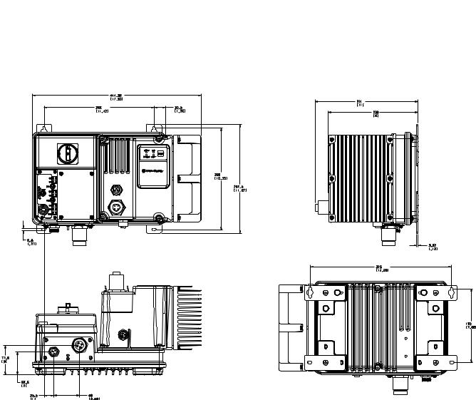
Dimensions for Bulletin 280G/281G Dimensions are shown in millimeters (inches). Dimensions are not intended to be used for manufacturing purposes. All dimensions are subject to change.
Figure 2.1 Dimensions for IP67/NEMA Type 4 with ArmorConnect
Connectivity
Installation and Wiring |
2-5 |
|
|
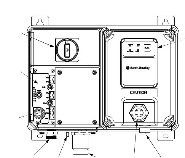
Figure 2.2 Bulletin 280G/281G ArmorStart® with DeviceNet™
Communication Protocol
Local Disconnect
LED Status
Indication
6 Inputs (Micro/M12)
DeviceNet Connection  (Mini/M18)
Control Power |
|
3-Phase Power |
Motor |
Control Brake |
|
Receptacle |
Ground Terminal |
Receptacle |
Connection |
||
|

2-6 |
Installation and Wiring |
|
|
Dimensions for Bulletin 284G
Dimensions are shown in millimeters (inches). Dimensions are not intended to be used for manufacturing purposes. All dimensions are subject to change.
Figure 2.3 Dimensions for 2 Hp (1.5 kW) and below @ 460V AC, IP67/NEMA Type 4 with ArmorConnect connectivity
Installation and Wiring |
2-7 |
|
|
Dimensions for Bulletin 284G, Continued
Dimensions are shown in millimeters (inches). Dimensions are not intended to be used for manufacturing purposes. All dimensions are subject to change.
Figure 2.4 Dimensions for 3 Hp (2.2 kW) and above @ 460V AC, IP67/NEMA Type 4 with ArmorConnect connectivity

2-8 |
Installation and Wiring |
|
|
Dimensions for Bulletin 1000
Dimensions are shown in millimeters (inches). Dimensions are not intended to be used for manufacturing purposes. All dimensions are subject to change.
Figure 2.5 Dimensions for 7.5 Hp (5.5 kW) and 10 Hp (7.5 kW) @ 460V AC, IP67/NEMA Type 4 with ArmorConnect Connectivity

Installation and Wiring |
2-9 |
|
|
Dimensions for Bulletin 1000, Continued
Dimensions are shown in millimeters (inches). Dimensions are not intended to be used for manufacturing purposes. All dimensions are subject to change.
Figure 2.6 Dimensions for 15 Hp (11 kW) @ 460V AC, IP67/NEMA Type 4 with ArmorConnect Connectivity

2-10 |
Installation and Wiring |
|
|
Figure 2.7 Bulletin 284G ArmorStart
Local Disconnect
LED Status
Indication
6 Inputs (Micro/M12)
Control Brake
Connector
DeviceNet Connection  (Mini/M18)
Control Power |
Ground |
3-Phase |
|
Motor |
|
Brake Connector |
Connector |
||||
Receptacle |
|||||
Terminal |
Receptacle |
||||
|
|
|
Installation and Wiring |
2-11 |
|
|
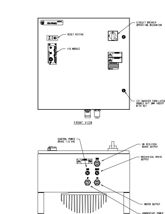
Figure 2.8 Bulletin 1000 ArmorStart

2-12 |
Installation and Wiring |
|
|
Figure 2.9 Bulletin 1000 ArmorStart
 Loading...