


 Loading...
Rockwell Automation 2711-KA1, 2711-KC1, 2711-TA1, 2711-TA4, 2711-TC1 User Manual
...
PanelViewt1200 Operator Terminals
(Catalog Numbers 2711-KA1, KC1, TA1, TC1, TA4, TC4)
User Manual

Important User Information |
Solid-state equipment has operational characteristics differing from those |
|
of electromechanical equipment. ªSafety Guidelines for the Application, |
|
Installation and Maintenance of Solid State Controlsº (Publication |
|
SGI±1.1) describes some important differences between solid-state |
|
equipment and hard-wired electromechanical devices. Because of this |
|
difference, and also because of the wide variety of uses for solid-state |
|
equipment, all persons responsible for applying this equipment must satisfy |
|
themselves that each intended application of this equipment is acceptable. |
|
In no event will the Allen-Bradley Company be responsible or liable for |
|
indirect or consequential damages resulting from the use or application of |
|
this equipment. |
|
The examples and diagrams in this manual are included solely for |
|
illustrative purposes. Because of the many variables and requirements |
|
associated with any particular installation, the Allen-Bradley Company |
|
cannot assume responsibility or liability for actual use based on the |
|
examples and diagrams. |
|
No patent liability is assumed by Allen-Bradley Company with respect to |
|
use of information, circuits, equipment, or software described in this |
|
manual. |
|
Reproduction of the contents of this manual, in whole or in part, without |
|
written permission of the Allen-Bradley Company is prohibited. |
|
Throughout this manual we use notes to make you aware of safety |
|
considerations. |
|
|
|
Attention Identifies information about practices or circumstances |
|
that can lead to personal injury or death, property damage, or |
|
economic loss. |
Attentions help you:
identify a hazard avoid the hazard
recognize the consequences
Important Identifies information that is especially important for successful application and understanding of the product.
PanelBuilder, PanelView, Data Highway Plus, DH+, SLC and SLC 500 are trademarks, and PLC, PLC-2, and PLC-3 are registered trademarks of Allen-Bradley Company, Inc.
Intel is a trademark of Intel Corp.
IBM, PC, AT, XT, PS/2 and PC DOS are registered trademarks of International Business Machines Corporation
Epson is a registered trademark of Seiko Epson Corporation
Microsoft Windows is a trademark, and Microsoft, MS, and MS-DOS are registered trademarks of Microsoft Corporation

Table of Contents
Preface . . . . . . . . . . . . . . . . . . . . . . . . . . . . . . . . . . . . . . . |
|
P 1 |
Manual Overview . . . . . . . . . . . . . . . . . . . . . . . . . . . . . . . . . . . . |
|
P 1 |
Intended Audience . . . . . . . . . . . . . . . . . . . . . . . . . . . . . . . . . . . |
|
P 1 |
. . . . . . . . . . . . . . . . . . . . . . . . . . . . . . . . . . .Glossary of Terms |
|
P 1 |
. . . . . . . . . . . . . . . . . . . . . . . . . . . . . . . . . .Related Publications |
|
P 3 |
After Sales Support . . . . . . . . . . . . . . . . . . . . . . . . . . . . . . . . . . |
|
P 4 |
Introduction to PanelView 1200 Operator Terminals . . . . . . |
|
1 1 |
|
The PanelView 1200 Terminal Family . . . . . . . . . . . . . . . . . . . . . . |
|
1 1 |
|
Wide Range of Applications . . . . . . . . . . . . . . . . . . . . . . . . . . |
|
1 3 |
|
PanelView 1200 Features . . . . . . . . . . . . . . . . . . . . . . . . . . . . . . |
|
1 3 |
|
. . . . . . . . . . . . . . . . . . . .Cost Optimized for OEM Applications |
|
1 3 |
|
Rugged, High Quality Design . . . . . . . . . . . . . . . . . . . . . . . . . |
|
1 3 |
|
Panel or 19" Rack Mounting . . . . . . . . . . . . . . . . . . . . . . . . . . |
|
1 3 |
|
12" Monochrome or Color Display . . . . . . . . . . . . . . . . . . . . . . |
|
1 4 |
|
Direct Connection to any Allen Bradley PLC Remote I/O Link . . . |
|
1 4 |
|
Direct or Data Highway Plus and Remote I/O Downloading . . . . |
|
1 4 |
|
Factory Installed Battery Provides Extended Back up . . . . . . . . |
|
1 4 |
|
User Definable Keys . . . . . . . . . . . . . . . . . . . . . . . . . . . . . . . |
|
1 5 |
|
Custom Keypad Legend Inserts . . . . . . . . . . . . . . . . . . . . . . . . |
|
1 5 |
|
Touch Screen Terminal for Simplicity and Space Saving . . . . . . |
|
1 5 |
|
. . . . . . . . . . . . . . . . . . .Message and Alarm Handling Utilities |
|
1 5 |
|
Built in Clock . . . . . . . . . . . . . . . . . . . . . . . . . . . . . . . . . . . . . |
|
1 6 |
|
Audio and Visual Feedback . . . . . . . . . . . . . . . . . . . . . . . . . . . |
|
1 6 |
|
Alarm Relay . . . . . . . . . . . . . . . . . . . . . . . . . . . . . . . . . . . . . . |
|
1 6 |
|
RS 232 Port . . . . . . . . . . . . . . . . . . . . . . . . . . . . . . . . . . . . . |
|
1 6 |
|
PanelView 1200 Terminal Diagnostics . . . . . . . . . . . . . . . . . . . |
|
1 7 |
|
Options and Accessories . . . . . . . . . . . . . . . . . . . . . . . . . . . . . . |
|
1 7 |
|
Upload/Download Cable . . . . . . . . . . . . . . . . . . . . . . . . . . . . . |
|
1 7 |
|
Optional Remote Keyswitch & RS 232 Port Assembly . . . . . . . . |
1 7 |
||
Optional EEPROM or EPROM for Back up or Additional |
|
|
|
Application Memory . . . . . . . . . . . . . . . . . . . . . . . . . . . . . . |
|
1 7 |
|
Functional Variations Among Terminal Types . . . . . . . . . . . . . . |
|
1 8 |
|
Keypad Terminals . . . . . . . . . . . . . . . . . . . . . . . . . . . . . . . . . . . |
|
1 8 |
|
Function Keys . . . . . . . . . . . . . . . . . . . . . . . . . . . . . . . . . . . . |
|
1 9 |
|
Numeric Keypad . . . . . . . . . . . . . . . . . . . . . . . . . . . . . . . . . . |
|
1 9 |
|
Special Keys . . . . . . . . . . . . . . . . . . . . . . . . . . . . . . . . . . . . . |
1 10 |
||
Touch Screen Terminals . . . . . . . . . . . . . . . . . . . . . . . . . . . . . . . |
1 10 |
||
Objects, Windows, and PLC Control Options . . . . . . . . . . . . . . . . |
1 11 |
||
. . . . . . . . . . . .Objects Common to All PanelView 1200 Terminals |
1 13 |
||
Objects for the Keypad Terminal . . . . . . . . . . . . . . . . . . . . . . . . . |
1 15 |
||
Objects for the Touch Screen Terminal . . . . . . . . . . . . . . . . . . . . . |
1 16 |
||
ii |
Table of Contents |
Information and Alarm Windows . . . . . . . . . . . . . . . . . . . . . . . . . |
1 16 |
. . . . . . . . . . . . . . . . . . . . . .Summary of PLC Controlled Options |
1 17 |
Applicable Programmable Controllers and Connections . . . . . . . . . |
1 17 |
PLC 5/11, 5/15, 5/20, 5/25, 5/30, 5/40, 5/60 and 5/250 Processors |
1 18 |
PLC 5/10 Processor . . . . . . . . . . . . . . . . . . . . . . . . . . . . . . . . |
1 18 |
PLC 3 and PLC 3/10 Processors . . . . . . . . . . . . . . . . . . . . . . . |
1 18 |
PLC 2 Family Processors via 1771 SN or 1772 SD2 . . . . . . . . . |
1 18 |
SLC 5/02 via 1747 SN . . . . . . . . . . . . . . . . . . . . . . . . . . . . . . |
1 19 |
1771 SN I/O Subscanner Module . . . . . . . . . . . . . . . . . . . . . . |
1 19 |
. . . . . . . . . . . . . . . . . . . . . . . . . .6008 SI IBM PC I/O Scanner |
1 19 |
6008 SV VME I/O Scanner . . . . . . . . . . . . . . . . . . . . . . . . . . . |
1 19 |
6008 SQ DEC Q BUS I/O Scanner . . . . . . . . . . . . . . . . . . . . . |
1 19 |
PanelView 1200 Terminal Functions . . . . . . . . . . . . . . . . . . |
|
2 1 |
|
Contrast, Brightness and the Mode Select Keyswitch . . . . . . . . . . |
|
2 1 |
|
. . . . . . . . . . . . . . . . . . . . . . . . . . . . . . . . . . . . .Fault Conditions |
|
2 2 |
|
. . . . . . . . . . . . . . . . . . . . . . . . . . . . . . . . . . . . .Major Faults |
|
2 2 |
|
. . . . . . . . . . . . . . . . . . . . . . . . . . . . . . . . . . . . .Minor Faults |
|
2 2 |
|
Power Up Functions . . . . . . . . . . . . . . . . . . . . . . . . . . . . . . . . . . |
|
2 3 |
|
Checksum and Read/Write Memory Tests . . . . . . . . . . . . . . . . |
|
2 3 |
|
Battery Failure Test . . . . . . . . . . . . . . . . . . . . . . . . . . . . . . . . |
|
2 4 |
|
Communication Test . . . . . . . . . . . . . . . . . . . . . . . . . . . . . . . . |
|
2 5 |
|
Watchdog Test . . . . . . . . . . . . . . . . . . . . . . . . . . . . . . . . . . . . |
|
2 5 |
|
Starting Up the Terminal in Configuration Mode . . . . . . . . . . . . . . . |
|
2 5 |
|
The Configuration Mode Menu . . . . . . . . . . . . . . . . . . . . . . . . . . |
|
2 6 |
|
Upload/Download . . . . . . . . . . . . . . . . . . . . . . . . . . . . . . . . . . |
|
2 6 |
|
Serial Port . . . . . . . . . . . . . . . . . . . . . . . . . . . . . . . . . . . . . . . |
|
2 7 |
|
Rack Assignments . . . . . . . . . . . . . . . . . . . . . . . . . . . . . . . . . |
|
2 8 |
|
Access Codes . . . . . . . . . . . . . . . . . . . . . . . . . . . . . . . . . . . . |
|
2 9 |
|
Audio Response . . . . . . . . . . . . . . . . . . . . . . . . . . . . . . . . . . |
2 10 |
||
Alarm Relay . . . . . . . . . . . . . . . . . . . . . . . . . . . . . . . . . . . . . . |
2 10 |
||
Preset Operations . . . . . . . . . . . . . . . . . . . . . . . . . . . . . . . . . |
2 10 |
||
Time and Date . . . . . . . . . . . . . . . . . . . . . . . . . . . . . . . . . . . . |
2 12 |
||
Screen Saver . . . . . . . . . . . . . . . . . . . . . . . . . . . . . . . . . . . . |
2 12 |
||
. . . . . . . . . . . . . . . . . . . . . . . . . . . . . . . . . .Screen Alignment |
2 13 |
||
. . . . . . . . . . . . . . . . . . . . . . . . . . . .Stuck Button/Cell Timeout |
2 14 |
||
False Depression Test (Touch Screen Only) . . . . . . . . . . . . . . . |
2 14 |
||
User EPROM/EEPROM Power Up Test . . . . . . . . . . . . . . . . . . |
2 15 |
||
Pass Through Download Options . . . . . . . . . . . . . . . . . . . . . . |
2 17 |
||
Unit Tests . . . . . . . . . . . . . . . . . . . . . . . . . . . . . . . . . . . . . . . |
2 21 |
||
Run Mode Functions . . . . . . . . . . . . . . . . . . . . . . . . . . . . . . . . . |
2 23 |
||
On line Diagnostic Testing . . . . . . . . . . . . . . . . . . . . . . . . . . . . . |
2 24 |
||
. . . . . . . . . . . . . . . . . . . . . . . . .PLC Communication Timeout |
2 24 |
||
Invalid Screen Request . . . . . . . . . . . . . . . . . . . . . . . . . . . . . . |
2 24 |
||
Application Data Checksum . . . . . . . . . . . . . . . . . . . . . . . . . . |
2 24 |
||
Table of Contents |
|
|
iii |
Battery Failure . . . . . . . . . . . . . . . . . . . . . . . . . . . . . . . . . . . . |
2 24 |
||
. . . . . . . . . . . . . . . . . . . . . . . .PanelView 1200 Terminal Printing |
2 24 |
||
Print Priorities . . . . . . . . . . . . . . . . . . . . . . . . . . . . . . . . . . . . |
2 25 |
||
. . . . . . . . . . . . . . . . . . . . . . . . . . . . . . . . . .Page Formatting |
2 25 |
||
Non Printable Characters . . . . . . . . . . . . . . . . . . . . . . . . . . . . |
2 26 |
||
Printer Errors . . . . . . . . . . . . . . . . . . . . . . . . . . . . . . . . . . . . . |
2 26 |
||
Installing Your PanelView 1200 Terminal . . . . . . . . . . . . . . |
|
3 1 |
|
The PanelView 1200 Terminal . . . . . . . . . . . . . . . . . . . . . . . . . . . |
|
3 2 |
|
The RS 232 Port . . . . . . . . . . . . . . . . . . . . . . . . . . . . . . . . . . |
|
3 2 |
|
The Alarm Relay Connector . . . . . . . . . . . . . . . . . . . . . . . . . . |
|
3 3 |
|
. . . . . . . . . . . . . . . . . . . . . . . . . . .The Remote I/O Connector |
|
3 4 |
|
The AC Power Connector . . . . . . . . . . . . . . . . . . . . . . . . . . . . |
|
3 4 |
|
Installing a User PROM . . . . . . . . . . . . . . . . . . . . . . . . . . . . . . . |
|
3 5 |
|
PanelView 1200 Terminal Dimensions . . . . . . . . . . . . . . . . . . . . . |
|
3 9 |
|
Installation Notes . . . . . . . . . . . . . . . . . . . . . . . . . . . . . . . . . . |
3 11 |
||
. . . . . . . . . . . . . . . . . . . . . . . .PanelView 1200 Terminal Cutouts |
3 11 |
||
Keypad Terminals (2711 KA1, 2711 KC1) . . . . . . . . . . . . . . . . . |
3 12 |
||
Touch Screen Terminals (2711 TA1, TC1) . . . . . . . . . . . . . . . . |
3 13 |
||
Touch Screen Terminals (2711 TA4, TC4) . . . . . . . . . . . . . . . . |
3 14 |
||
Optional Clip or Stud Rack Mount Kits . . . . . . . . . . . . . . . . . . . . . |
3 15 |
||
Remote Keyswitch Assembly Dimensions . . . . . . . . . . . . . . . . . . |
3 16 |
||
Upload/Download Cable . . . . . . . . . . . . . . . . . . . . . . . . . . . . . . . |
3 16 |
||
Verifying the PanelView 1200 Terminal Operation . . . . . . . |
|
4 1 |
|
Testing the PanelView 1200 Terminal . . . . . . . . . . . . . . . . . . . . . . |
|
4 1 |
|
. . . . . . . . . . . . . . . . . . . . . . . . .Downloading the Application File |
|
4 2 |
|
. . . . . . . . . . . . . . . . . . . . .Matching Communications Settings |
|
4 2 |
|
. . . . . . . . . . . . . . . . . . . . . . . . . .Downloading the Application |
|
4 2 |
|
. . . . . . . . . . . . . . . . . . . . . . . . . . . .Running the Application File |
|
4 3 |
|
Connecting the PLC Controller . . . . . . . . . . . . . . . . . . . . . . . . . . |
|
4 3 |
|
Testing Retentive Objects . . . . . . . . . . . . . . . . . . . . . . . . . . . . |
|
4 4 |
|
Testing the Whole System . . . . . . . . . . . . . . . . . . . . . . . . . . . . . . |
|
4 4 |
|
Maintaining Your PanelView 1200 Terminal . . . . . . . . . . . . |
|
5 1 |
|
Cleaning . . . . . . . . . . . . . . . . . . . . . . . . . . . . . . . . . . . . . . . . . . |
|
5 1 |
|
Changing the Filter on Color Units . . . . . . . . . . . . . . . . . . . . . . . . |
|
5 2 |
|
Screen Saver . . . . . . . . . . . . . . . . . . . . . . . . . . . . . . . . . . . . . . |
|
5 2 |
|
Degauss . . . . . . . . . . . . . . . . . . . . . . . . . . . . . . . . . . . . . . . . . . |
|
5 2 |
|
. . . . . . . . . . . . . . . . . . . . . . . . . . . . . . . .Strong Magnetic Fields |
|
5 3 |
|
iv |
Table of Contents |
Specifications . . . . . . . . . . . . . . . . . . . . . . . . . . . . . . . . . . |
|
A 1 |
Design Certifications, Standards and Compliances . . . . . . . . . . . . |
|
A 1 |
Design Standards Complied With . . . . . . . . . . . . . . . . . . . . . . |
|
A 1 |
Terminal Weights . . . . . . . . . . . . . . . . . . . . . . . . . . . . . . . . . . . . |
|
A 2 |
Keypad Terminals . . . . . . . . . . . . . . . . . . . . . . . . . . . . . . . . . |
|
A 2 |
Front Panel Design . . . . . . . . . . . . . . . . . . . . . . . . . . . . . . . . . . |
|
A 2 |
Touch Screen Terminals . . . . . . . . . . . . . . . . . . . . . . . . . . . . . |
|
A 2 |
CRT Display . . . . . . . . . . . . . . . . . . . . . . . . . . . . . . . . . . . . . . . |
|
A 3 |
. . . . . . . . . . . . . . . . . . . . . . . . . .Color Unit Display Attributes |
|
A 3 |
. . . . . . . . . . . . . . . . . . . .Monochrome Unit Display Attributes |
|
A 4 |
. . . . . . . . . . . . . . . . . . . . . . . .PLC Remote I/O Communications |
|
A 4 |
Serial Communications Port . . . . . . . . . . . . . . . . . . . . . . . . . . . . |
|
A 5 |
AC Power . . . . . . . . . . . . . . . . . . . . . . . . . . . . . . . . . . . . . . . . . |
|
A 5 |
Fuses . . . . . . . . . . . . . . . . . . . . . . . . . . . . . . . . . . . . . . . . . . . . |
|
A 6 |
. . . . . . . . . . . . . . . . . . . . . . . . . . . . . . . . . . . . . .Character Set |
|
A 6 |
User Memory . . . . . . . . . . . . . . . . . . . . . . . . . . . . . . . . . . . . . . . |
|
A 6 |
Alarm Relay . . . . . . . . . . . . . . . . . . . . . . . . . . . . . . . . . . . . . . . . |
|
A 6 |
Batteries . . . . . . . . . . . . . . . . . . . . . . . . . . . . . . . . . . . . . . . . . . |
|
A 7 |
Time and Date Clock . . . . . . . . . . . . . . . . . . . . . . . . . . . . . . . . . |
|
A 7 |
Ambient Operating Temperature Limits . . . . . . . . . . . . . . . . . . . |
|
A 8 |
. . . . . . . . . . . . . . . . . . .Temperature, Humidity, and High Altitude |
|
A 8 |
Storage Temperature Limits . . . . . . . . . . . . . . . . . . . . . . . . . . |
|
A 8 |
Humidity . . . . . . . . . . . . . . . . . . . . . . . . . . . . . . . . . . . . . . . . |
|
A 8 |
Maximum Altitude . . . . . . . . . . . . . . . . . . . . . . . . . . . . . . . . . . |
|
A 8 |
Monochrome Terminals . . . . . . . . . . . . . . . . . . . . . . . . . . . . . |
|
A 8 |
Heat Generation . . . . . . . . . . . . . . . . . . . . . . . . . . . . . . . . . . . . |
|
A 8 |
Color Terminals . . . . . . . . . . . . . . . . . . . . . . . . . . . . . . . . . . . |
|
A 8 |
. . . . . . . . . . . . . . . . . . . . . . . . . . . . . . . . .Shock Amplitudes |
|
A 9 |
Shock and Vibration . . . . . . . . . . . . . . . . . . . . . . . . . . . . . . . . . . |
|
A 9 |
. . . . . . . . . . . . . . . . .Vibration Amplitudes for Operating Units |
|
A 9 |
Vibration Amplitudes for Non Operating Units . . . . . . . . . . . . . . |
|
A 9 |
Troubleshooting . . . . . . . . . . . . . . . . . . . . . . . . . . . . . . . . |
|
B 1 |
Verifying Configuration Settings . . . . . . . . . . . . . . . . . . . . . . . . . . |
|
B 1 |
PanelView 1200 Major Fault Error Messages . . . . . . . . . . . . . . . . |
|
B 1 |
PanelView 1200 Minor Fault Error Messages . . . . . . . . . . . . . . . . |
|
B 2 |
PLC Communication Problems . . . . . . . . . . . . . . . . . . . . . . . . . . |
|
B 3 |
Pass Through Upload/Download Problems . . . . . . . . . . . . . . . . . |
|
B 4 |
PLC Controllers Required for Pass Through . . . . . . . . . . . . . . . |
|
B 5 |
Common Error Messages for Manual Address |
|
|
Source Configuration . . . . . . . . . . . . . . . . . . . . . . . . . . . . |
|
B 6 |
Common Pass Through Error Codes . . . . . . . . . . . . . . . . . . . . |
|
B 6 |
PanelBuilder Problems . . . . . . . . . . . . . . . . . . . . . . . . . . . . . . . . |
|
B 7 |

Preface
Preface
Manual Overview |
This manual describes the features and specifications of PanelView 1200 |
|
terminals. PanelView 1200 terminals are available as keypad or touch |
|
screen terminals, with color or monochrome display. |
|
Note The term ªPanelView 1200º is the new name for PanelView |
|
terminals. It refers to all 12-inch CRT PanelView terminals, from Series A |
|
upwards. |
|
The manual provides information and examples for: |
|
installing and maintaining a PanelView 1200 terminal |
|
operating a PanelView 1200 terminal |
|
connecting a PanelView 1200 terminal to an Allen-Bradley |
|
Programmable Logic Controller (PLCr) |
|
troubleshooting a PanelView 1200 terminal |
Intended Audience |
This manual is written to help you install and maintain PanelView 1200 |
|
terminals. |
Glossary of Terms |
The following terms are used throughout this manual. |
|
Application File: A PanelView 1200 terminal application file contains a |
|
series of screens and configurations which, when interpreted and executed |
|
by PanelView 1200, replace the functions of a control panel of buttons, |
|
switches and indicators. The screens are created on a development |
|
computer running PanelBuilder Development Software or |
|
PanelBuilder 1200 Configuration Software for Windows, and then saved |
|
in an application file on the development computer's disk. The application |
|
file is then downloaded to a PanelView 1200 terminal where it stays in |
|
battery-backed RAM. |
|
Battery-Backed RAM: Application files are stored in the PanelView 1200 |
|
terminal's random access memory (RAM). The RAM is backed by an |
|
internal battery so that the application file and the status of the retentive |
|
objects are maintained even when AC power is switched off. |
P-1

Preface
Hex Files: Application files which have been converted into Intel Hex format for transfer to user PROMs.
Object: An object is an individual component of a PanelView 1200 screen. Each object takes the function of a button, switch or indicator on a control panel. The objects can be dynamicÐthey can change color or value and can display information. Each object is defined by the developer of the PanelView 1200 screen. Examples of objects include Push Buttons, Selectors, Bar Graphs, Numeric Displays, etc.
PanelBuilder Software: The program runs on the development computer to develop application files for PanelView 1200 terminals. There are two types of PanelBuilder software: PanelBuilder 1200 Configuration Software for Windows and PanelBuilder Development Software for DOS.
PanelView 1200 Terminal: A type of Allen-Bradley terminal with a touch screen or rugged keypad, designed for easy operator interaction with a PLC system over the Remote I/O link.
Retentive: An object is described as retentive when it ªretainsº its PLC value in the PanelView 1200 terminal after a screen change, an operator's object action, and even after the terminal's power cycle. For example, when a maintained push button is pressed, the corresponding PLC input is set to 1 and will not change until the button is pressed a second time. Retentive objects always display their current states or values.
Screen: A display containing objects (such as push buttons or bar graphs) which can monitor and control a PLC system. Screens are created with either type of the PanelBuilder software.
SRAM: Static Random Access Memory. A type of memory that can maintain its contents through the use of a battery. It does not require continuous refreshing to maintain its contents.
System Memory: The read-only memory that contains the operating firmware for the PanelView 1200 terminal.
Upload/Download: Downloading is the process of transferring an application file from a development computer running either type of the PanelBuilder software, to a PanelView 1200 terminal. Uploading is the process of transferring an application file from the terminal back to the development computer.
User PROM: The read-only memory chip that can be used to contain a back-up copy of an application file, or to increase the memory available for the application file from 64K to 128K. The chip can be either an EPROM or an EEPROM.
P-2

Preface
There are two types of user PROM chips that can be used in PanelView 1200 terminal: EPROMs and EEPROMs. EPROMs are Electrically Programmable Read Only Memory chips. EEPROMs are Electrically Erasable Programmable Read Only Memory chips.
The user PROMs store application files in memory that is protected from power failure and failure of the internal battery. A PROM burner is required to copy application files into a user EPROM.
If your system includes a user EEPROM, application files downloaded through the Upload/Download cable will be stored in both battery-backed RAM and in the EEPROM. No PROM burner is required.
Window: An area on the screen containing information. These windows are triggered by the PLC controller and overlay any screen that is displayed.
Related Publications |
The following related publications provide additional information on |
|
|
programmable controllers and I/O scanners. |
|
|
Publication |
Pub. No. |
|
|
|
|
1772 SD/SD2 Remote I/O Scanner/Distribution Panel |
1772 2.18 |
|
|
|
|
1775 S4A I/O Scanner-Programmer Interface Module User’s Manual |
1775 6.5.1 |
|
|
|
|
1775 S5, 1775 SR5 I/O Scanner Communication Adapter Module User’s |
1775 6.5.5 |
|
Manual |
|
|
|
|
|
5150 RS PI Start up and Integration Manual |
5000 6.5.1 |
|
|
|
|
6008 SI IBM PC I/O Scanner User’s Manual |
6008 6.5.3 |
|
6008 SV VME I/O Scanner User’s Manual |
6008 6.5.2 |
|
|
|
|
6008 SQ Q Bus I/O Scanner Utility Software User’s Manual |
6008 6.4.1 |
|
|
|
|
1771 SN Sub I/O Scanner Module Data Sheet |
1771 2.91 |
|
|
|
|
1747 SN RIO Scanner User’s Manual |
1747 NM005 |
|
|
|
|
Publication |
Pub. No. |
|
|
|
|
1772 LP2 PLC 2/20 Programming and Operations Manual |
1772 6.8.1 |
|
|
|
|
1772 LP3 PLC 2/30 Controller Programming and Operations Manual |
1772 6.8.3 |
|
|
|
|
PLC 3 Family Controller Programming Reference Manual |
1775 6.4.1 |
|
|
|
|
PLC 5 Family Programmable Controllers Hardware Installation Manual |
1785 6.6.1 |
|
|
|
|
PLC 5 Programming Software |
6200 6.4.7 |
|
|
|
|
5250 LP1, LP2 PLC 5/250 Programming Manual |
5000 6.4.8 |
|
|
|
|
SLC 500 Family of Programmable Controllers Advanced Programming |
1747 NM002 |
|
Software User’s Manual |
|
|
|
|
P-3

Preface
|
To identify the manuals referring to these programmable controllers, |
|
|
consult the Publications Index, Publication SD499, available from |
|
|
Allen-Bradley. |
|
After Sales Support |
If you need help with your PanelView 1200 terminal, contact: |
|
|
Allen-Bradley |
|
|
Global Technical Support |
|
|
6680 Beta Drive |
|
|
Mayfield Village, Ohio 44143 |
|
|
Inside USA and Canada: |
1-800-289-2279 |
Outside USA and Canada, contact your local Allen-Bradley office or call
USA (216) 646-6800.
Your terminal's catalog number, series, revision letter and firmware revision are shown on the label on the back of the terminal. Please have this information ready when you call for technical support.
Please register your PanelView 1200 terminal by mailing the registration card to the address above, or by FAXing the card to (216) 646-6770.
P-4
The PanelView 1200 Terminal
Family
Chapter 1
Introduction to PanelView 1200 Operator Terminals
This chapter provides an overview of the PanelView 1200 terminals. It describes:
the types and features of PanelView 1200 terminals
the available options and accessories
the supported Allen-Bradley programmable controllers and remote I/O scanners
PanelView 1200 terminals provide a fast, easy, flexible and low cost operator interface for a PLC system. They are ideal replacements for traditional control panels.
PanelView 1200 terminals are pre-assembled and ready to install in a control panel cut-out or 19º rack. They connect directly to any Allen-Bradley remote I/O link.
An Allen-Bradley, IBM or compatible computer (the development computer) is used to create PanelView 1200 terminal screens and functions. See the PanelBuilder Development Software User Manual for information on PanelBuilder Development Software for DOS. See the
PanelBuilder 1200 Configuration Software for Windows User Manual for more information on PanelBuilder 1200 Configuration Software for Windows.
The PanelView 1200 terminal family includes the following products and corresponding catalog numbers:
Table 1.A
PanelView 1200 Products and Catalog Numbers
Product |
Description |
Catalog Number |
|
|
|
Keypad Terminal |
Amber display |
2711 KA1 |
|
|
|
Keypad Terminal |
Color display |
2711 KC1 |
|
|
|
Touch Screen Terminal |
Amber display, clip mount, NEMA 12 |
2711 TA1 |
|
|
|
Touch Screen Terminal |
Color display, clip mount, NEMA 12 |
2711 TC1 |
|
|
|
Touch Screen Terminal |
Amber display, stud mount, NEMA 4X |
2711 TA4 |
|
(indoor use only) |
|
|
|
|
1-1

Chapter 1
Introduction to PanelView 1200 Operator
Terminals
Product |
Description |
Catalog Number |
|
|
|
Touch Screen Terminal |
Color display, stud mount, NEMA 4x |
2711 TC4 |
|
(indoor use only) |
|
|
|
|
PanelView 1200 Terminal |
Includes PanelBuilder Development |
2711 ND1 |
Development Kit |
Software (for DOS), |
|
|
Upload/Download cable and |
|
|
manuals |
|
|
|
|
PanelBuilder 1200 Configuration |
Includes PanelBuilder 1200 |
2711 ND1W |
Software for Windows Development |
Configuration Software for Windows, |
|
Kit |
PanelView 1200 Transfer Utility |
|
|
Software, and manuals |
|
|
|
|
Upload/Download Cable |
Upload/Download cable for |
2711 NC1 |
|
transferring applications serially |
|
|
|
|
Remote Keyswitch & RS-232 Port |
Allows remote mode selection and |
2711 NC2 |
Assembly |
serial port access |
|
|
|
|
EPROM Chip Set |
For application file back up - Series |
2711 NM1 |
|
C and earlier logic boards |
|
EEPROM Chip Set - Series C and earlier
For application file back up or extra |
2711 NM2 |
application RAM - Series C and earlier logic boards
Rack Mount Kit for Touch Screen |
To rack mount TA1 and TC1 terminals |
2711 NR1 |
|
Terminals |
|
|
|
|
|
|
|
Rack Mount Kit for Touch Screen |
To rack mount TC4 and TA4 terminals |
2711 NR2 |
|
Terminals |
|
|
|
|
|
|
|
V5 |
Touch Screen Firmware Upgrade |
To upgrade Series C and earlier |
2711 TUV5C |
Kit |
|
Touch Screen logic boards to V5 |
|
|
|
firmware |
|
|
|
|
|
V5 |
Keypad Firmware Upgrade Kit |
To upgrade Series C and earlier |
2711 KUV5C |
|
|
Keypad logic boards to V5 firmware |
|
|
|
|
|
V5 |
Touch Screen Firmware Upgrade |
To upgrade Series D and E Touch |
2711 TUV5D |
Kit |
|
Screen logic boards to V5 firmware |
|
|
|
|
|
V5 |
Keypad Firmware Upgrade Kit |
To upgrade Series D and E Keypad |
2711 KUV5D |
|
|
logic boards to V5 firmware |
|
|
|
|
|
EEPROM Chip |
For application file back up and extra |
2711 NM3 |
|
|
|
application RAM - Series D and E |
|
|
|
logic boards |
|
|
|
|
|
Lens Overlay |
Anti glare protective overlay |
2711 NV1 |
|
|
|
|
|
1-2

Chapter 1
Introduction to PanelView 1200 Operator
Terminals
Table 1.B
PanelView 1200 Terminal Replacement Parts and Numbers
Replacement Part |
Part Number |
Catalog Number |
|
|
|
Spare Mode Select Keys |
46715 414 01 |
|
|
|
|
Series D and E Logic Board |
46715 448 01 |
|
|
|
|
Touch Screen Mounting Hardware |
46715 416 01 |
|
for NEMA 12 mounting |
|
|
|
|
|
Touch Screen - Series C or earlier |
46715 460 01 |
|
|
|
|
Touch Screen - Series D and E |
|
2711-NT1 |
|
|
|
Keyswitch Assembly |
46715 418 01 |
|
|
|
|
Blank Keypad Legend Inserts |
46715 419 01 |
|
|
|
|
Remote I/O Connector |
22112 046 03 |
|
|
|
|
Keypad Faceplate - Series D and E |
|
2711-NK1 |
|
|
|
PanelView 1200 Features |
Wide Range of Applications |
|
PanelView 1200 terminals provide many pre-configured functions |
|
allowing for a wide range of applications across many industries. This |
|
enables you to standardize on PanelView 1200 terminals, thereby |
|
simplifying service stock and reducing the cost and time required to train |
|
your personnel on many different products. |
Cost Optimized for OEM Applications
Since PanelBuilder software resides outside the PanelView 1200 terminal, the terminal is not burdened with this overhead.
Rugged, High Quality Design
PanelView 1200 terminals are designed to strict Allen-Bradley specifications, with high grade components and rugged construction for long trouble-free operation in harsh industrial environments.
Panel or 19" Rack Mounting
All PanelView 1200 terminals can be panel or 19º rack-mounted. Keypad and stud-mounted touch screen terminals are rated NEMA 4X (Indoor use only). Clip-mounted touch screen terminals are rated NEMA 12.
1-3

Chapter 1
Introduction to PanelView 1200 Operator
Terminals
12" Monochrome or Color Display
All PanelView 1200 terminals have a 12º display in monochrome (amber) or color. Color terminals can display 8 colors at a time from a choice of 16.
Direct Connection to any Allen Bradley PLC Remote I/O Link
You can integrate a PanelView 1200 terminal quickly and easily into any
PLC system capable of supporting the Allen-Bradley 1771 Remote I/O
Link.
A PanelView 1200 terminal appears as one or more PLC I/O racks on an Allen-Bradley PLC Remote I/O link; it can be configured as up to 8 different racksÐor fractional racksÐwith any valid PLC rack numbers.
Communications between the PLC controller and the PanelView 1200 terminal are provided through the discrete I/O image table area, and up to 5 block transfers (up to 32 words per block). Block transfers allow you to transfer more information at a time than does discrete I/O. The
PanelView 1200 terminals can also communicate to the SLC-5/02 controller through the use of the 1747-SN module.
Direct or Data Highway Plus and Remote I/O Downloading
Application files can be downloaded from the development computer to the terminal via the Upload/Download cable (an RS-232 connection), or via a Data Highway Plus, using the PLC-5 Pass-Through feature.
By using the Data Highway Plus for downloading, you can download to several terminals from a single development computer without having to go from terminal to terminal, connecting the Upload/Download cable for each one.
Factory Installed Battery Provides Extended Back up
The built-in battery maintains power to the terminal's memory so the application file is not lost when the terminal is switched off. PanelView 1200 terminals come equipped with a RAM memory chip that requires minimal power from the lithium battery. Also, the battery is not burdened when AC power is applied to the terminal. This provides exceptional life for the battery, which is expected to last for the life of the terminal.
1-4

Chapter 1
Introduction to PanelView 1200 Operator
Terminals
User Definable Keys
The keypad terminal has 21 user-definable keys on its front panel. Each one can perform a variety of operationsÐfrom turning on PLC input bits to changing screens. PanelView 1200 terminals are extremely flexible: each key can be assigned a different function for each screen.
Custom Keypad Legend Inserts
The function keys on keypad terminals are pre-labeled at the factory, but you can create key labels to suit your application. The included Legend Kit provides blank card material that can be written on with most types of markers or paste-on labels. Replacing the labels on the terminals is a quick and easy task.
Touch Screen Terminal for Simplicity and Space Saving
A touch-sensitive surface overlays the monitor on the touch screen terminal. Selections are made by touching the display directly. Since a keypad is not required, these terminals require less panel space.
Message and Alarm Handling Utilities
A PanelView 1200 terminal application can be set up with stored messages that can be triggered by the PLC controller. There are three kinds of message displays:
Local Message Displays can appear in any free location on a specific screen (875 messages maximum)
Information Windows can pop up regardless of the screen currently displayed (496 messages maximum)
Alarm Windows can pop up regardless of the screen currently displayed (496 messages maximum)
For each type of message displayedÐlocal, information or alarmÐthere is a message list. Using PanelBuilder software, you can add or edit messages. Messages are numbered and listed in numerical order in the message list.
See your PanelBuilder 1200 Configuration Software for Windows User
Manual for more information on PanelBuilder 1200 Configuration Software for Windows. See your PanelBuilder Development Software User
Manual for more information on PanelBuilder Development Software for DOS.
1-5

Chapter 1
Introduction to PanelView 1200 Operator
Terminals
Built in Clock
The battery-backed clock runs even when the terminal is powered down. PanelView 1200 can display the current time and date and can send it to the PLC controller. The clock may also be set by the PLC controller.
Audio and Visual Feedback
A PanelView 1200 terminal can be configured to:
activate a beeper each time a function button or touch cell is pressed
light up a screen button (if it has a border) when its function key or touch cell is pressed.
allow the PLC controller to activate the beeper at the terminal
allow Alarm Messages to activate the beeper at the terminal
Alarm Relay
You can attach a horn or a warning light to the PanelView 1200 terminal's alarm relay. Relay connections are made via the terminal block labeled ªAlarm Contactsº at the rear of the terminal. Specific alarm messages, or a PLC program, can then trigger the relay.
Attention The Alarm Relay must be used only as a warning system, not for control purposes.
RS 232 Port
All PanelView 1200 terminals include one RS-232 port for printing on-line alarm messages, uploading and downloading application files, and printing screens.
1-6

Chapter 1
Introduction to PanelView 1200 Operator
Terminals
|
PanelView 1200 Terminal Diagnostics |
|
When a PanelView 1200 terminal starts up, it performs a number of fault |
|
detection tests. The PanelView 1200 terminal also performs continuous |
|
tests for fault conditions when it is communicating online with the PLC |
|
controller. In the event of a fault, a message appears, pinpointing the exact |
|
nature of the fault. |
|
An operator can also initiate diagnostic tests from the terminal. |
|
For a description of the diagnostic tests, and the various fault conditions, |
|
refer to Chapter 2, PanelView 1200 Terminal Functions, in this manual. |
Options and Accessories |
Optional hardware is available that you may find convenient to use with |
|
either type of the PanelBuilder software and the PanelView 1200 terminal. |
|
For catalog numbers see tables 1.A and 1.B. |
|
Upload/Download Cable |
|
The Upload/Download cable connects the development computer's RS-232 |
|
Port to the PanelView 1200 terminal's RS-232 Port. You use it to transfer |
|
applications serially between the development computer and the |
|
PanelView 1200 terminal If you have a number of terminals, you may want |
|
to order more than one Upload/Download cable. |
|
Optional Remote Keyswitch & RS 232 Port Assembly |
|
On the back of all PanelView 1200 terminals is a Mode Select Keyswitch |
|
and RS-232 Port. The Remote Keyswitch and RS-232 Port Assembly |
|
allows you to mount the port and keyswitch to the front of your control |
|
panel while maintaining a NEMA 4X seal. This is convenient if you don't |
|
have easy access to the rear of the PanelView 1200 terminal. See Chapter |
|
3, Installing Your PanelView 1200 Terminal, for details on mounting and |
|
dimensions. |
|
Optional EEPROM or EPROM for Back up or Additional Application |
|
Memory |
|
Earlier PanelView 1200 terminals contained two sockets for optional |
|
EPROM or EEPROM chips. Series D and E PanelView 1200 terminals |
|
have one socket for an optional EPROM/EEPROM, called the user PROM. |
1-7

Chapter 1
Introduction to PanelView 1200 Operator
Terminals
an EPROM can be used for application file back-up. The application file is programmed into the EPROM with a PROM burner. Once programmed, it cannot be erased or overwritten.
an EEPROM can be used for application file back-up or for extra application memory
when the EEPROM is used for application back-up, the downloaded application file is automatically copied to the EEPROM during the download operation
an EEPROM can also be used to increase the memory available for application file storage from 64K to 128K. If the EEPROM is used in this way, it cannot be used as back-up for the application file.
Functional Variations Among Terminal Types
The terminals are configured almost identically with these exceptions:
buttons are set up differently on keypad terminals and touch screen terminals
certain screen objects are specific to keypad terminals, others to touch screen terminals. For more information on objects see your
PanelBuilder 1200 Configuration Software for Windows User Manual, or your PanelBuilder Development Software User Manual.
foreground and background colors can be assigned only for color PanelView 1200 terminals. Inverse video and intensity settings are assigned for monochrome terminals
Keypad Terminals |
The keypad terminal has: |
21 user-definable function keys
a keypad for entering numeric values
up, down, left and right arrow keys
Home, Enter, Select, Cancel, Raise, Lower and Backspace keys
The user-definable function keys on keypad terminals are pre-labeled at the factory, but you can create key labels (legends) to suit your application. The replacement key legends slide in from the rear of the faceplate. The included Legend Kit provides blank card material that can be written on with most types of markers or paste-on labels.
1-8

Chapter 1
Introduction to PanelView 1200 Operator
Terminals
You can also configure the terminal to beep when a key is pressed.
Figure 1.1 |
|
|
|
|
|
|
|
|
|
|
|
Keypad Terminal |
|
|
|
|
|
|
|
|
|
|
|
|
|
|
|
|
|
|
|
PanelView |
|
||
|
|
|
|
|
|
|
|
7 |
8 |
9 |
|
|
|
|
|
|
|
|
|
4 |
5 |
6 |
Numeric |
|
|
|
|
|
|
|
F17 |
|
|
|
|
|
|
|
|
|
|
|
1 |
2 |
3 |
Keypad |
|
|
|
|
|
|
|
|
|
||||
|
|
|
|
|
|
|
F18 |
• |
|
|
|
|
|
|
|
|
|
|
0 |
- |
|
||
|
|
|
|
|
|
|
|
|
|||
|
|
|
|
|
|
|
F19 |
|
|
|
|
|
|
|
|
|
|
|
F20 |
|
|
|
|
|
|
|
|
|
|
|
F21 |
|
HOME |
" |
|
|
|
|
|
|
|
|
|
|
|
|
Special Keys |
|
|
|
|
|
|
|
|
|
|
|
|
|
|
|
|
|
|
|
|
Raise |
SELECT |
|
|
F1 |
F2 |
F3 |
F4 |
F5 |
F6 |
F7 |
F8 |
Lower |
CANCEL |
|
|
|
|
|
|
||||||||
F9 |
F10 |
F11 |
F12 |
F13 |
F14 |
F15 |
F16 |
|
|
|
|
Function Keys |
21000 |
Function Keys
When creating screens, you can assign any of the 21 function keys to objects so that they can perform a wide variety of functions, ranging from turning on PLC input bits to changing screens. Keys can have different functions for each screen created.
Numeric Keypad
The keypad terminal has a numeric input keypad that includes number keys, Enter, Backspace, ± (negative), and . (decimal) keys. When you need to make a numeric entry, you call up a pop-up Numeric Entry Scratchpad that displays the numbers as you type.
The Numeric Entry Scratchpad is displayed on the screen any time the operator is required to enter numeric data and send it to a PLC controller.
1-9

Chapter 1
Introduction to PanelView 1200 Operator
Terminals
Special Keys
There are a series of special keys on the keypad terminal:
the arrow keys are used with the Set Bit and Numeric Cursor Points and the ASCII Input object
Home, Select work with the Set Bit and Numeric Input Cursor Points
Cancel is designed to be used with all numeric keypads, Numeric Input and Set Bit Cursor Points.
Raise and Lower are used with Numeric Input Cursor Points only.
The three blank keys at the bottom right are reserved for future development, and are not configurable.
For more details, see your PanelBuilder Development Software User
Manual, or your PanelBuilder 1200 Configuration Software for Windows
User Manual.
Touch Screen Terminals |
Touch screen terminals are simple to use: an operator presses a selection |
|
directly on the screen to carry out the desired task. |
Figure 1.2
Touch Screen Terminal
PanelView |
21003 |
1-10
Chapter 1
Introduction to PanelView 1200 Operator
Terminals
The touch screen terminal contains 120 touch cells. Each touch cell is 2 characters high by 8 characters wide. You can configure the terminal to beep when a touch cell is pressed.
16 characters fit in one touch cell
20002
Touch cells are grouped to create different types and sizes of buttons. The following figure illustrates a single touch cell ON button with double height and double width characters, and a solid border. You can activate input functions by touching the appropriate object on the touch screen.
Button
Border
20216
Objects, Windows, and PLC
Control Options
The objects, windows and PLC control options are listed in three groups: those used on both keypad and touch screen terminals, those used for keypad terminals only, and those used for touch screen terminals only.
You will note that the objects are identified as either dynamic or static. Dynamic objects interact with the PLC controller; static objects do not.
For complete details on all objects, windows and options that can be controlled from the PLC controller, refer to your PanelBuilder Development Software User Manual, or your PanelBuilder 1200 Configuration Software for Windows User Manual.
The following table lists the objects, and indicates which terminal types they are suited for. It also shows whether the object is dynamic or static.
1-11

Chapter 1
Introduction to PanelView 1200 Operator
Terminals
Table 1.C
Objects for PanelView 1200 Terminals
Object |
Type |
Keypad or Touch |
|
|
Screen terminal |
|
|
|
Momentary Push Button (Normally Open) |
Dynamic |
Both |
|
|
|
Momentary Push Button (Normally Closed) |
Dynamic |
Both |
|
|
|
Latched Input Push Button |
Dynamic |
Both |
|
|
|
Maintained Push Button |
Dynamic |
Both |
|
|
|
Interlocked Push Button |
Dynamic |
Both |
|
|
|
Control List Selector with Enter |
Dynamic |
Both |
|
|
|
Control List Selector without Enter |
Dynamic |
Both |
|
|
|
Set Bit Cursor Point |
Dynamic |
Keypad |
|
|
|
Goto Screen Button |
Static |
Both |
|
|
|
Return to Previous Screen Button |
Static |
Both |
|
|
|
Screen List Selector |
Static |
Both |
|
|
|
Screen Keypad Enable Button |
Static |
Keypad |
|
|
|
Keypad Screen Selector |
Static |
Touch Screen |
|
|
|
Multistate Indicator |
Dynamic |
Both |
|
|
|
List Indicator |
Dynamic |
Both |
|
|
|
Set Value Button |
Dynamic |
Both |
|
|
|
Increment Value Button |
Dynamic |
Both |
|
|
|
Decrement Value Button |
Dynamic |
Both |
|
|
|
Numeric Data Display |
Dynamic |
Both |
|
|
|
Numeric Keypad Enable Button |
Dynamic |
Keypad |
|
|
|
Numeric Input Cursor Point |
Dynamic |
Keypad |
|
|
|
Numeric Keypad (small and large) |
Dynamic |
Touch Screen |
|
|
|
ISA Symbol |
Dynamic |
Both |
|
|
|
Bar Graphs (vertical or horizontal) |
Dynamic |
Both |
|
|
|
Time Display |
Dynamic |
Both |
|
|
|
Date Display |
Dynamic |
Both |
|
|
|
ASCII Input |
Dynamic |
Both |
|
|
|
Scrolling List Object |
Dynamic |
Both |
|
|
|
Screen Print Button |
Static |
Both |
|
|
|
Local Message Display |
Dynamic |
Both |
|
|
|
ASCII Display |
Dynamic |
Both |
|
|
|
Text |
Static |
Both |
|
|
|
Line, Line Arrows, Line Connect Characters |
Static |
Both |
|
|
|
Box |
Static |
Both |
|
|
|
Arc |
Static |
Both |
|
|
|
Circle |
Static |
Both |
|
|
|
1-12

Objects Common to All PanelView 1200 Terminals
Chapter 1
Introduction to PanelView 1200 Operator
Terminals
The following objects can be displayed on both the keypad terminal and the touch screen terminal:
Momentary Push Button (Normally Open) turns on (sets to 1) a PLC input control bit, as long as the button is held.
Momentary Push Button (Normally Closed) resets a PLC input control bit that is normally set to 1. This bit stays off as long as the button is pressed.
Latched Input Push Button turns on a PLC input control bit and holds the bit on until the PanelView 1200 terminal sees a PLC output bit (handshake bit) turn on.
Maintained Push Button turns on a specific PLC input control bit until the button is pressed a second time.
Interlocked Push Buttons are several push buttons functioning as a group. When you press one of the buttons, it cancels the other buttons and makes the selection. The PLC controller is informedÐvia a common PLC input addressÐwhich button in the group is the currently selected option.
Control List Selector with Enter contains a vertical list of operator choices. An operator can use the object's Up Cursor and Down Cursor buttons to move an arrow through the available selections. The selection is sent to the PLC controller only when the Enter button is pressed.
Control List Selector without Enter contains a vertical list of choices. The operator uses the object's Up Cursor and Down Cursor buttons to move through the available selections. The current selection is automatically sent to the PLC controller via the object's PLC input control address.
ªGoto Screenº Button allows the operator to switch to an assigned screen.
ªReturn To Previous Screenº Button switches back to the previous screen.
Screen List Selector allows an operator to choose a screen from a list.
Multistate Indicator is a display area with up to sixteen different display states, each with a unique combination of text, colors and attributes. The value in the PLC address determines which state is displayed.
1-13

Chapter 1
Introduction to PanelView 1200 Operator
Terminals
List Indicator displays a list of PLC states and highlights the current state. The value of the PLC address determines the item that will be highlighted in the list.
Set Value Button transfers a pre-defined value to the PLC controller via the assigned PLC input address.
Increment Value Button increases the value stored at a PLC input address each time the button is pushed. If the button is held down, the PLC controller input value continues to increase to a pre-assigned upper limit.
Decrement Value Button decreases the value stored at a PLC input address each time the button is pushed. If the button is held down, the PLC controller value continues to decrease to a pre-assigned bottom limit.
Numeric Data Display displays the current value of an assigned PLC controller address (binary, BCD, or integer). Scaling (Y=Mx+b) and other options can be used to display the number in appropriate units.
ISA Symbols (32 in total) allow you to assign display attributes to four possible states for each symbol object. The symbols have two sizes: large and small.
Bar Graphs can be used to monitor changing conditions, such as temperature or fluid levels. Each graph can be up to 80 characters wide and 24 characters high.
Time Display can be located anywhere on the screen.
Date Display can be located anywhere on the screen.
ASCII Input allows the PanelView 1200 terminal operator to send
ASCII strings of up to 64 characters to the assigned PLC input address.
Scrolling List object is an extended and enhanced control list selector/list indicator that is not limited by the number of lines on the screen. The Scrolling List can consist of any combination of local message display, multistate indicator, and numeric display lists with up to 999 items in each list. The Scrolling List object reduces PLC ladder logic and addressing typically needed to display and edit large amounts of data.
This object can be used to control and monitor sequential operations in both auto and manual modes or to provide operators with a selection list.
1-14

|
|
|
|
|
Chapter 1 |
|
|
Introduction to PanelView 1200 Operator |
|
|
Terminals |
|
Screen Print Button allows an operator to print any screen currently |
|
|
||
|
displayed on the PanelView 1200 terminal. |
|
|
Local Message Display can be defined as a rectangular area of any size, |
|
|
and placed in any location on the PanelView 1200 terminal screen. A |
|
|
PLC control address is assigned to the object, allowing the PLC |
|
|
controller to trigger any one of up to 875 messages to appear in this |
|
|
area. |
|
|
ASCII Display is used to display a character string, sent from the PLC |
|
|
controller, directly on the PanelView 1200 terminal. The display is |
|
|
updated whenever the string changes. |
|
|
Text is used for screen titles, to provide instructions, or for any text that |
|
|
is not bound to an object. |
|
|
Lines (Horizontal, vertical and diagonal) are used to illustrate, and to |
|
|
separate sections of screens. |
|
|
Line Arrows are used to illustrate. |
|
|
Line Connect Characters are used to connect lines and lines and |
|
|
objects. |
|
|
Boxes are graphic objects like lines, which can surround other objects or |
|
|
simply illustrate. |
|
|
Arcs are used to illustrate quarter, semi, and three quarter circles, as |
|
|
well as circles. They can also be used to connect line objects to form |
|
|
rounded corners. |
|
|
Circles are composed of four arcs. They are used to illustrate. |
|
Objects for the Keypad |
The following objects can be displayed only on a keypad terminal: |
|
Terminal |
Numeric Input Cursor Point consists of a numeric display and a |
|
|
||
|
cursor character. This object can be used to enter numbers into an array |
|
|
of numeric fields similar to an array of thumb-wheel switches on a |
|
|
control panel. This object has an associated PLC input address in which |
|
|
the value is communicated to the PLC controller. |
|
|
Numeric Keypad-Enable Button pops up the Numeric Entry |
|
|
Scratchpad in which the operator can enter a number. The number is |
|
|
then stored in the specified PLC input address. |
|
|
Screen Keypad-Enable Button pops up the Numeric Entry Scratchpad |
|
|
in which the operator can enter a screen number. The screen with that |
|
|
number is displayed. |
|
1-15

Chapter 1
Introduction to PanelView 1200 Operator
Terminals
|
Set Bit Cursor Point consists of a bit and a cursor character. This |
|
object is used to ªpointº to a screen character. Several set bit cursor |
|
points can be in the same screen. Each one can have a different |
|
(user-defined) pointer; only the current pointer is visible and blinking. |
|
The current cursor point's input bit is always on, so the PLC controller |
|
always ªknowsº the current selection. |
|
Both the set bit and numeric input cursor points can be used on the same |
|
screen. |
Objects for the Touch Screen |
The following objects can be displayed only on a touch screen terminal: |
Terminal |
Keypad Screen Selector allows an operator to display a screen by |
|
|
|
entering the screen number. The selector is available in large and small |
|
sizes. |
|
Numeric Keypad is used to send a value to the PLC controller. A PLC |
|
input address is assigned to each Numeric Keypad; the value that the |
|
operator enters is stored at this address. The keypad is available in large |
|
and small sizes. |
Information and Alarm |
The Information and Alarm Windows can pop up on the screen at any time |
Windows |
to display important information: |
|
Information Window displays a message when triggered by the PLC |
|
controller. The window remains until the operator presses the Clear |
|
button, or until the PLC controller clears it. There can be as many as |
|
496 different messages for the Information Window. |
|
Alarm Window is similar to the Information Window but with many |
|
additional features. Each message can be configured to sound the audio |
|
indicator (beeper), trip the alarm relay or print a message on a printer. |
|
Alarms are time and date stamped and listed in the order they occur. The |
|
operator can acknowledge the alarm, clear the display, silence the alarm, |
|
view the Alarm History Screen, or view the Alarm Status Screen. There |
|
can be as many as 496 different messages for the Alarm Window. |
1-16

|
|
|
|
|
Chapter 1 |
|
|
Introduction to PanelView 1200 Operator |
|
|
Terminals |
|
|
|
Summary of PLC Controlled |
The following options can be controlled by the PLC controller: |
|
Options |
PLC Controlled Audio allows the PLC controller to control the |
|
|
||
|
PanelView 1200 terminal's audio beeper. A PLC bit address is assigned. |
|
|
When the PLC controller sets this bit, the terminal's beeper is activated. |
|
|
This does not interfere with the Alarm Window's use of the beeper. |
|
|
PLC Controlled Alarm Relay allows the PLC controller to control the |
|
|
PanelView 1200 terminal's alarm relay. A PLC bit address is assigned, |
|
|
and when the PLC controller sets this bit, the terminal's alarm relay is |
|
|
energized. This does not interfere with the Alarm Window's use of the |
|
|
relay. |
|
|
PLC Controlled Alarm Quantity/Accum Time Reset allows the PLC |
|
|
controller to reset the alarm count and the accumulated time-in-alarm |
|
|
total. These totals are shown in the Alarm Status screen. |
|
|
PLC Controlled Screen Number allows the PLC controller to control |
|
|
which screen is displayed. When the PLC controller puts a screen |
|
|
number in an assigned address, the PanelView 1200 terminal displays |
|
|
the screen. This PLC controlled screen change always has precedence |
|
|
over operator-controlled screen changes, and operator-generated screen |
|
|
changes are allowed only if the PLC address contains 0. |
|
|
PLC Controlled Screen Print allows the PLC controller to trigger a |
|
|
printout of the screen displayed on the PanelView 1200 terminal. |
|
|
PLC Controlled Time and Date allows the PanelView 1200 terminal |
|
|
to read the time and date from the PLC controller and set its internal |
|
|
clock. |
|
|
PLC Controlled Clear Window clears the alarm window, the alarm |
|
|
beeper and the alarm relay when a 0 to 1 transition is detected in the |
|
|
assigned PLC address bit. |
|
|
PLC Controlled Silence Alarms silences the beeper and deactivates |
|
|
the alarm relay when a 0 to 1 transition is detected on this bit. |
|
Applicable Programmable |
PanelView 1200 terminals can be connected to any Allen-Bradley 1771 |
|
Controllers and Connections |
Remote I/O Link. Applicable host controllers include almost all |
|
|
Allen-Bradley Programmable Logic Controllers as well as certain IBM |
|
|
computers, VME Controllers, and the DEC Q-Bus interface. |
|
|
Newly released Allen-Bradley programmable controllers that are not yet |
|
|
listed will support PanelView 1200 terminals, as long as they support the |
|
|
1771 remote I/O. |
|
1-17

Chapter 1
Introduction to PanelView 1200 Operator
Terminals
The PanelView 1200 terminal appears as one or more I/O rack(s) to a PLC controller. It has the same configurabilityÐand moreÐas a standard I/O rack. Refer to your applicable Allen-Bradley Programmable Controller and Remote I/O Scanner user's manuals for various connection and remote I/O configuration limitations.
PLC 5/11, 5/15, 5/20, 5/25, 5/30, 5/40, 5/60 and 5/250 Processors
You can connect one or more PanelView 1200 terminals directly to a PLC-5 Remote I/O Port (in Scanner Mode) along with other I/O racks. If the PLC-5 Remote I/O Port is used in the adapter mode, one or more PanelView 1200 terminals can be connected to that PLC-5 along with other I/O racks via a 1771-SN I/O Subscanner Module.
All Series C Rev A and later terminals can communicate at 230.4K baud with any PLC-5 capable of supporting that baud rate.
If you are using a PLC-5/15 with partial rack addressing and block transfers, you must use PLC-5/15 series B, revision J or later.
PLC 5/10 Processor
One or more PanelView 1200 terminals can be connected to this processor along with other I/O racks via the 1771-SN I/O Subscanner Module.
PLC 3 and PLC 3/10 Processors
One or more PanelView 1200 terminals can be connected directly to a
PLC-3 or PLC-3/10 remote I/O Scanner along with other I/O racks.
If you are using a 1775-S4A Remote Scanner/Distribution panel, you must use Series B or higher.
PLC 2 Family Processors via 1771 SN or 1772 SD2
This includes the PLC-2/05, 2/15, 2/30, etc. One or more PanelView 1200 terminals can be connected to these processors along with other I/O racks via the 1771-SN I/O Subscanner Module.
If you are using a 1772-SD2 Scanner/Distribution panel, you must use revision 3 or later.
1-18

Chapter 1
Introduction to PanelView 1200 Operator
Terminals
SLC 5/02 via 1747 SN
One or more PanelView 1200 terminals can be connected to the 1747-SN I/O Subscanner Module (SLC±5/02 RIO connection) for the SLC±5/02 processor. Each module provides an additional remote I/O link for the host programmable controller. The rack range of the 1747-SN is 0 to 3.
Important No block transfers are possible with the SLC-5/02 and 1747-SN Series A module.
1771 SN I/O Subscanner Module
One or more 1771-SN I/O Subscanner Modules can be installed in any standard Allen-Bradley 1771 I/O rack. Each module provides an additional remote I/O link for the host programmable controller. One or more PanelView 1200 terminals can be connected to any of the previously mentioned processors along with other I/O racks via a 1771-SN I/O Subscanner Module. Refer to the 1771-SN Sub I/O Scanner Module Data
Sheet for specific details.
6008 SI IBM PC I/O Scanner
This module can be installed in an IBM PC or compatible computer to provide the computer with an Allen-Bradley 1771 Remote I/O Link. You can then connect Allen-Bradley Remote I/O racks and devices such as the PanelView 1200 terminal to this computer.
6008 SV VME I/O Scanner
This module can be installed in a VME backplane, providing the VME controller with an Allen-Bradley 1771 Remote I/O Link. Allen-Bradley Remote I/O racks and devices such as the PanelView 1200 terminal can then be connected to this VME controller.
6008 SQ DEC Q BUS I/O Scanner
This module can be installed into a DEC Q-Bus controller to provide it with an Allen-Bradley 1771 Remote I/O Link. Allen-Bradley Remote I/O racks and devices such as the PanelView 1200 terminal can then be connected to this controller.
1-19
Contrast, Brightness and the
Mode Select Keyswitch
Chapter 2
PanelView 1200 Terminal Functions
This chapter describes how to use the PanelView 1200 terminal's two operating modes and discusses the power-up and on-line tests that the terminal performs.
The PanelView 1200 terminal has two modes of operation: Configure mode and Run mode. Configure mode allows you to set up the terminal, and Run mode executes the application file. The PanelView 1200 terminal communicates with your PLC controller only when it's in Run mode, so set it to this mode to monitor and control your PLC application.
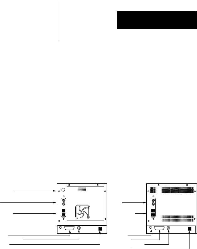
The following illustration shows the rear panel of a PanelView 1200 terminal. Note the location of the Mode Select Keyswitch, the brightness control, (Monochrome terminals), and the contrast control (Color terminals).
Contrast Control
Fuses
Terminal Blocks
RS 232 Port
Mode Select Keyswitch PLC interface
Figure 1.1
PanelView 1200 Terminal Rear Panels
Fuses |
Terminal Blocks |
........ |
Brightness
RS 232 Port
Mode Select Keyswitch
PLC interface
Color Back Panel
........
Monochrome Back Panel
20153
The Brightness and the Contrast Controls adjust the terminal display intensity. The Mode Select Keyswitch switches between Configuration and Run modes.
2-1
Loading...