


 Loading...
PowerFlex® 22-COMM-B
BACnet MS/TP Adapter
Firmware Version 1.xxx
User Manual

Important User Information
Solid state equipment has operational characteristics differing from those of electromechanical equipment. Safety Guidelines for the Application, Installation and Maintenance of Solid State Controls (Publication SGI-1.1 available from your local Rockwell Automation sales office or online at http:// www.rockwellautomation.com/literature) describes some important differences between solid state equipment and hard-wired electromechanical devices. Because of this difference, and also because of the wide variety of uses for solid state equipment, all persons responsible for applying this equipment must satisfy themselves that each intended application of this equipment is acceptable.
In no event will Rockwell Automation, Inc. be responsible or liable for indirect or consequential damages resulting from the use or application of this equipment.
The examples and diagrams in this manual are included solely for illustrative purposes. Because of the many variables and requirements associated with any particular installation, Rockwell Automation, Inc. cannot assume responsibility or liability for actual use based on the examples and diagrams.
No patent liability is assumed by Rockwell Automation, Inc. with respect to use of information, circuits, equipment, or software described in this manual.
Reproduction of the contents of this manual, in whole or in part, without written permission of Rockwell Automation, Inc. is prohibited.
Throughout this manual, when necessary we use notes to make you aware of safety considerations.
WARNING: Identifies information about practices or circumstances that can cause an explosion in a hazardous environment, which may
!! lead to personal injury or death, property damage, or economic loss.
Important: Identifies information that is critical for successful application and understanding of the product.
ATTENTION: Identifies information about practices or circumstances that can lead to personal injury or death, property damage, or economic
!! loss. Attentions help you identify a hazard, avoid a hazard, and recognize the consequences.
Shock Hazard labels may be located on or inside the equipment (e.g., drive or motor) to alert people that dangerous voltage may be present.
Burn Hazard labels may be located on or inside the equipment (e.g., drive or motor) to alert people that surfaces may be at dangerous temperatures.
Allen-Bradley, PowerFlex, DriveExplorer, DriveExecutive, DriveTools SP, and ControlFLASH are trademarks of Rockwell Automation, Inc.
Trademarks not belonging to Rockwell Automation are property of their respective companies.

Summary of Changes
The information below summarizes the changes made to this manual since its last release (October 2006):
Description of Changes |
Page(s) |
Updated information in the “Related Documentation” section. |
P-1 |
In the “Compatible Products” section, added the PowerFlex 4M drive. |
1-3 |
NOTE: The 22-COMM-B adapter must have firmware version 1.003 (or later) |
|
to be compatible with the PowerFlex 4M drive. |
|
Updated information in the “Using the Optional, External PowerFlex 4-Class |
3-2 |
HIM” section. |
|
Added the new section “Flash Updating the Adapter.” |
3-10 |
Revised Table 4.A to include the PowerFlex 4M drive. |
4-3 |

soc-ii Summary of Changes

|
Table of Contents |
|
Preface |
About This Manual |
|
|
Related Documentation . . . . . . . . . . . . . . . . . . . . . . . . . . . . |
. P-1 |
|
Rockwell Automation Support. . . . . . . . . . . . . . . . . . . . . . . |
. P-2 |
|
Conventions Used in this Manual . . . . . . . . . . . . . . . . . . . . . |
P-2 |
Chapter 1 |
Getting Started |
|
|
Components . . . . . . . . . . . . . . . . . . . . . . . . . . . . . . . . . . . . . . |
1-1 |
|
Features . . . . . . . . . . . . . . . . . . . . . . . . . . . . . . . . . . . . . . . . . |
1-2 |
|
Compatible Products . . . . . . . . . . . . . . . . . . . . . . . . . . . . . . . |
1-3 |
|
Required Equipment . . . . . . . . . . . . . . . . . . . . . . . . . . . . . . . |
1-3 |
|
Safety Precautions . . . . . . . . . . . . . . . . . . . . . . . . . . . . . . . . . |
1-4 |
|
Quick Start . . . . . . . . . . . . . . . . . . . . . . . . . . . . . . . . . . . . . . . |
1-6 |
|
Status Indicators. . . . . . . . . . . . . . . . . . . . . . . . . . . . . . . . . . . |
1-7 |
Chapter 2 |
Installing the Adapter |
|
|
Preparing for an Installation. . . . . . . . . . . . . . . . . . . . . . . . . . |
2-1 |
|
Commissioning the Adapter. . . . . . . . . . . . . . . . . . . . . . . . . . |
2-1 |
|
Connecting the Adapter to the Drive . . . . . . . . . . . . . . . . . . . |
2-6 |
|
Applying Power . . . . . . . . . . . . . . . . . . . . . . . . . . . . . . . . . . . |
2-9 |
|
Connecting the Drive/Adapter to the Network . . . . . . . . . . |
2-11 |
Chapter 3 |
Configuring the Adapter |
|
|
Configuration Tools . . . . . . . . . . . . . . . . . . . . . . . . . . . . . . . . |
3-1 |
|
Using the Optional, External PowerFlex 4-Class HIM . . . . . |
3-2 |
|
Setting the Device Instance Number . . . . . . . . . . . . . . . . . . . |
3-4 |
|
Setting a Comm Loss Action . . . . . . . . . . . . . . . . . . . . . . . . . |
3-6 |
|
Setting the Comm Loss Time. . . . . . . . . . . . . . . . . . . . . . . . . |
3-7 |
|
Setting the Baud Rate. . . . . . . . . . . . . . . . . . . . . . . . . . . . . . . |
3-8 |
|
Resetting the Adapter. . . . . . . . . . . . . . . . . . . . . . . . . . . . . . . |
3-9 |
|
Viewing the Adapter Status Using Parameters . . . . . . . . . . |
3-10 |
|
Flash Updating the Adapter . . . . . . . . . . . . . . . . . . . . . . . . . |
3-10 |
Chapter 4 |
Using BACnet Objects |
|
|
Understanding BACnet Objects . . . . . . . . . . . . . . . . . . . . . . . |
4-1 |
|
Basic Drive Operation on the Network . . . . . . . . . . . . . . . . . |
4-2 |
|
Supported BACnet Objects . . . . . . . . . . . . . . . . . . . . . . . . . . |
4-3 |

ii |
Table of Contents |
|
|
Chapter 5 Troubleshooting
Understanding the Status Indicators . . . . . . . . . . . . . . . . . . . 5-1
PORT Status Indicator . . . . . . . . . . . . . . . . . . . . . . . . . . . . . . 5-2
MOD Status Indicator . . . . . . . . . . . . . . . . . . . . . . . . . . . . . . 5-2
NET A Status Indicator . . . . . . . . . . . . . . . . . . . . . . . . . . . . . 5-3
NET B Status Indicator . . . . . . . . . . . . . . . . . . . . . . . . . . . . . 5-3
Viewing Adapter Diagnostic Items . . . . . . . . . . . . . . . . . . . . 5-4
Viewing and Clearing Events. . . . . . . . . . . . . . . . . . . . . . . . . 5-5
Appendix A Specifications
Communications . . . . . . . . . . . . . . . . . . . . . . . . . . . . . . . . . A-1
Electrical . . . . . . . . . . . . . . . . . . . . . . . . . . . . . . . . . . . . . . . A-1
Mechanical . . . . . . . . . . . . . . . . . . . . . . . . . . . . . . . . . . . . . . A-1
Environmental . . . . . . . . . . . . . . . . . . . . . . . . . . . . . . . . . . . A-2
Regulatory Compliance . . . . . . . . . . . . . . . . . . . . . . . . . . . . A-2
Appendix B Adapter Parameters
About Parameter Numbers. . . . . . . . . . . . . . . . . . . . . . . . . . . B-1
Parameter List . . . . . . . . . . . . . . . . . . . . . . . . . . . . . . . . . . . . B-1
Appendix C Protocol Implementation Conformance Statement (PICS)
Product Description . . . . . . . . . . . . . . . . . . . . . . . . . . . . . . . . C-1 BACnet Standardized Device Profile (Annex L) . . . . . . . . . . C-1 List all BACnet Interoperability Building Blocks Supported
(Annex K) . . . . . . . . . . . . . . . . . . . . . . . . . . . . . . . . . . . . C-1 Segmentation Capability . . . . . . . . . . . . . . . . . . . . . . . . . . . . C-1 Standard Object Types Supported . . . . . . . . . . . . . . . . . . . . . C-2 Data Link Layer Options . . . . . . . . . . . . . . . . . . . . . . . . . . . . C-3 Device Address Binding . . . . . . . . . . . . . . . . . . . . . . . . . . . . C-3 Networking Options. . . . . . . . . . . . . . . . . . . . . . . . . . . . . . . . C-3
Appendix D Routing Capability for Networked Drives Glossary
Index

Preface
About This Manual
Topic |
Page |
Related Documentation |
P-1 |
Rockwell Automation Support |
P-2 |
Conventions Used in this Manual |
P-2 |
Related Documentation
For: |
Refer to: |
Publication |
DriveExplorer™ |
http://www.ab.com/drives/driveexplorer, and |
— |
|
DriveExplorer online Help (installed with the software) |
|
DriveTools™ SP (includes |
http://www.ab.com/drives/drivetools, and |
— |
DriveExecutive™) |
DriveExecutive online Help (installed with the software) |
|
PowerFlex 4-Class HIM |
HIM Quick Reference |
22HIM-QR001 |
(22-HIM-A3 or 22-HIM-C2S) |
|
|
PowerFlex® 4 Drive |
PowerFlex 4 User Manual |
22A-UM001 |
|
PowerFlex 4 Quick Start |
22A-QS001 |
PowerFlex® 4M Drive (1) |
PowerFlex 4M User Manual |
22F-UM001 |
|
PowerFlex 4M Quick Start |
22F-QS001 |
PowerFlex® 40 Drive |
PowerFlex 40 User Manual |
22B-UM001 |
|
PowerFlex 40 Quick Start |
22B-QS001 |
PowerFlex® 400 Drive |
PowerFlex 400 User Manual |
22C-UM001 |
|
PowerFlex 400 Quick Start |
22C-QS001 |
(1)The 22-COMM-B adapter must have firmware version 1.003 (or later) to be compatible with the PowerFlex 4M drive.
You can view or download publications at http:// www.rockwellautomation.com/literature. To order paper copies of technical documentation, contact your local Rockwell Automation distributor or sales representative.
To find your Rockwell Automation distributor or sales representative, visit www.rockwellautomation.com/locations.
For information such as firmware updates or answers to drive-related questions, go to the Drives Service & Support web site at www.ab.com/ support/abdrives and click on the “Downloads” or “Knowledgebase” link.

P-2 About This Manual
Rockwell Automation Support
Rockwell Automation, Inc. offers support services worldwide, with over 75 sales/support offices, over 500 authorized distributors, and over 250 authorized systems integrators located throughout the United States alone. In addition, Rockwell Automation, Inc. representatives are in every major country in the world.
Local Product Support
Contact your local Rockwell Automation, Inc. representative for:
•Sales and order support
•Product technical training
•Warranty support
•Support service agreements
Technical Product Assistance
For technical assistance, please review the information in Chapter 5, Troubleshooting first. If you still have problems, then access the Allen-Bradley Technical Support web site at www.ab.com/support/ abdrives or contact Rockwell Automation, Inc.
Conventions Used in this Manual
This manual provides information about the adapter and using it with PowerFlex 4-Class drives. The adapter can be used with other products that support a DSI™ adapter, such as the DSI External Comms Kit (22-XCOMM-DC-BASE). Refer to the documentation for your product for specific information about how it works with the adapter.
The following conventions are used throughout this manual:
•Parameter names are shown in the format Parameter xx - [*]. The xx represents the parameter number, and the * represents the parameter name—for example, Parameter 01 - [Mode].
•Menu commands are shown in bold type face and follow the format Menu > Command. For example, if you read “Select File > Open,” you should click the File menu and then click the Open command.
•The firmware release is displayed as FRN X.xxx. The “FRN” signifies Firmware Release Number. The “X” is the major release number. The “xxx” is the minor update number.
Chapter 1
Getting Started
The adapter is intended for installation into a PowerFlex 40 or PowerFlex 400 drive and is used for network communication. The adapter can also be installed in a DSI External Comms Kit (22-XCOMM-DC-BASE). This kit enables PowerFlex 4 and PowerFlex 4M drives, which cannot accommodate an internally-mounted adapter, to connect to a BACnet MS/TP network. NOTE: The 22-COMM-B adapter must have firmware version 1.003 (or later) to be compatible with the PowerFlex 4M drive.
Topic |
Page |
Components |
1-1 |
Features |
1-2 |
Compatible Products |
1-3 |
Required Equipment |
1-3 |
Topic |
Page |
Safety Precautions |
1-4 |
Quick Start |
1-6 |
Status Indicators |
1-7 |
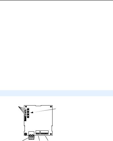
Components
Figure 1.1 Components of the Adapter

 LEDs are located on bottom side of adapter board
|
|
|
|
|
|
|
|
|
|
Item |
|
Component |
|
Description |
|
|
Status Indicators |
Four LEDs that indicate the status of the network connection, |
|
|
|
|
|
DSI, and the adapter. Refer to Chapter 5, Troubleshooting. |
|
|
DSI Connector |
|
A 20-pin, single-row shrouded male header. An Internal Interface |
|
|
|
|
cable connects to this connector and a connector on the drive. |
|
|
Terminal Block |
|
A 3-pin terminal block with mating 3-pin linear plug connects the |
|
|
|
|
adapter to the network. |
|
|
TERM, -BIAS, and |
Switches for turning on/off the adapter’s internal termination |
|
|
|
+BIAS Switches |
resistor and bias resistors. See Setting the TERM, -BIAS, and |
|
|
|
|
|
+BIAS Switches on page 2-4 for details. |
|
|
MAC Address |
|
Switches for setting the MAC address. See Setting the MAC |
|
|
Switches |
|
Address on page 2-2 for details. |

1-2 Getting Started
Features
The adapter features include:
•Typical mounting in a PowerFlex 40 or PowerFlex 400 drive. The adapter can also be installed in a DSI External Comms Kit (22-XCOMM-DC-BASE).
•Switches that enable you to:
–Set a MAC address before applying power to the drive.
–Turn on/off the adapter’s built-in termination resistor and bias resistors for optimizing operation on the network.
•A captive screw secures and grounds the adapter to the drive or, when mounted in a DSI External Comms Kit, to the kit’s metal enclosure.
•Compatibility with various configuration tools to configure the adapter and connected drive. The tools include an external PowerFlex 4-Class HIM (22-HIM-A3 or 22-HIM-C2S), and drive-configuration software such as DriveExplorer (version 3.01 or later) or DriveExecutive (version 3.01 or later).
•Status indicators that report the status of drive communications, the adapter, and network.
•Read and write access to parameters to configure and monitor parameter values over the network.
•User-defined fault actions to determine how the adapter and connected drive respond to I/O communication disruptions (Comm Loss Action) on the network.
Getting Started |
1-3 |
|
|
Compatible Products
The adapter is compatible with Allen-Bradley PowerFlex 4-Class (Component-Class) drives and other products that support an internal DSI adapter. At the time of publication, compatible products include:
•PowerFlex 4 drives (when used with DSI External Comms Kit)
•PowerFlex 4M drives(1) (when used with DSI External Comms Kit)
•PowerFlex 40 drives
•PowerFlex 400 drives
(1)The 22-COMM-B adapter must have firmware version 1.003 (or later) to be compatible with PowerFlex 4M drives.
Required Equipment
Equipment Shipped with the Adapter
When you unpack the adapter, verify that the package includes:
One adapter
One 15.24 cm (6 in.) Internal Interface cable
One 3-pin linear plug (plugged into the adapter socket)
One PowerFlex 4-Class DSI (Drive Serial Interface) Network Communications Adapter Installation Instructions (publication 22COMM-IN002)
User-Supplied Equipment
To install and configure the adapter, you must supply:
A small flathead screwdriver
A shielded, twisted wire pair to connect the adapter to the network
A configuration tool, such as:
–PowerFlex 4-Class HIM (22-HIM-A3 or 22-HIM-C2S) – required to access adapter parameters when not using DriveExplorer or DriveExecutive software
–DriveExplorer software (version 3.01 or later)
–DriveExecutive stand-alone software (version 3.01 or later) or bundled with the DriveTools SP suite (version 1.01 or later)
–Third-party network configuration software

1-4 Getting Started
Safety Precautions
Please read the following safety precautions carefully.
!
!
!
!
!
!
ATTENTION: Risk of injury or death exists. The PowerFlex drive may contain high voltages that can cause injury or death. Remove  power from the PowerFlex drive, and then verify power has been discharged before installing or removing an adapter.
ATTENTION: Risk of injury or equipment damage exists. Only personnel familiar with drive and power products and the associated  machinery should plan or implement the installation, start-up, configuration, and subsequent maintenance of the product using an adapter. Failure to comply may result in injury and/or equipment damage.
ATTENTION: Risk of equipment damage exists. The adapter contains ESD (Electrostatic Discharge) sensitive parts that can be  damaged if you do not follow ESD control procedures. Static control precautions are required when handling the adapter. If you are unfamiliar with static control procedures, refer to Guarding Against Electrostatic Damage (publication 8000-4.5.2).
ATTENTION: Risk of injury or equipment damage exists. If the adapter is transmitting control I/O to the drive, the drive may fault when  you reset the adapter. Determine how your drive will respond before resetting an adapter.
ATTENTION: Risk of injury or equipment damage exists.
Parameter 02 - [Comm Loss Action] lets you determine the action of  the adapter and connected drive if communications are disrupted. By
default, this parameter faults the drive. You can set this parameter so that the drive continues to run. Precautions should be taken to ensure that the setting of this parameter does not create a risk of injury or equipment damage. When commissioning the drive, verify that your system responds correctly to various situations (for example, a disconnected cable).
ATTENTION: Risk of injury or equipment damage exists. Parameter 03 - [Comm Loss Time] lets you determine how long it will take the  adapter to detect network communication losses. By default, this parameter sets the timeout to ten seconds. You can set it so that the duration is shorter, longer, or disabled. When set to disabled, this also disables adapter Parameter 02 - [Comm Loss Action]. Therefore, a communications fault action will be ignored. Take precautions to ensure that the setting does not create a risk of injury or equipment damage. When commissioning the drive, verify that your system responds correctly to various situations (for example, a disconnected cable).

Getting Started |
1-5 |
|
|
!
!
ATTENTION: Risk of injury or equipment damage exists. When a system is configured for the first time, there may be unintended or  incorrect machine motion. Disconnect the motor from the machine or process during initial system testing.
ATTENTION: Risk of injury or equipment damage exists. The examples in this publication are intended solely for purposes of  example. There are many variables and requirements with any application. Rockwell Automation, Inc. does not assume responsibility or liability (to include intellectual property liability) for actual use of the examples shown in this publication.

1-6 Getting Started
Quick Start
This section is provided to help experienced users quickly start using the adapter. If you are unsure how to complete a step, refer to the referenced chapter.
Step |
Action |
Refer to … |
|
1 |
Review the safety precautions for the adapter. |
Throughout this manual |
|
2 |
Verify that the PowerFlex drive is properly installed. |
Drive User Manual |
|
3 |
Commission the adapter. |
Chapter 2, |
|
|
Set a unique MAC address and, depending on where the |
Installing the Adapter |
|
|
PowerFlex drive nodes are located on the network, |
|
|
|
appropriately set the TERM, -BIAS, and +BIAS switches. |
|
|
4 |
Install the adapter. |
PowerFlex 4-Class DSI |
|
|
Verify that the PowerFlex drive is not powered. Then, |
Network Communication |
|
|
Adapter Installation |
||
|
connect the adapter to the drive using the Internal |
||
|
Instructions (publication |
||
|
Interface cable. Use the captive screw to secure and |
||
|
22COMM-IN002) and |
||
|
ground the adapter to the drive. |
||
|
|
||
|
When installing the adapter in a DSI External Comms Kit, |
Chapter 2, |
|
|
refer to the 22-XCOMM-DC-BASE Installation Instructions |
Installing the Adapter |
|
|
(publication 22COMM-IN001) supplied with the kit. |
|
|
5 |
Apply power to the adapter and verify key settings. |
Chapter 2, |
|
|
A. The adapter receives power from the drive. Verify |
Installing the Adapter |
|
|
|
||
|
|
that the adapter is installed correctly and then apply |
|
|
|
power to the drive. The PORT status indicator should |
|
|
|
be solid green. If it is red, there is a problem. Refer to |
|
|
|
Chapter 5, Troubleshooting. |
|
|
B. Verify/configure key adapter parameters. |
|
|
|
C. Configure/verify key drive parameters. |
|
|
6 |
Connect the adapter to the network. |
Chapter 2, |
|
|
Verify that the PowerFlex drive is not powered. Then, |
Installing the Adapter |
|
|
|
||
|
connect the adapter to the network using a shielded, |
|
|
|
twisted wire pair. |
|
|
7 |
Configure the adapter for your application. |
Chapter 3, |
|
|
Set adapter parameters for the following functions as |
Configuring the Adapter |
|
|
|
||
|
required by your application: |
|
|
|
• |
Fault actions |
|
|
• |
Baud rate |
|
8 |
Configure the controller to communicate with the |
Instructions for your |
|
|
adapter. |
controller’s programming |
|
|
Use the controller’s programming software to program the |
software |
|
|
controller. |
|
|
Getting Started |
1-7 |
|
|
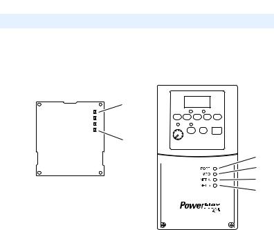
Status Indicators
The adapter uses four status indicators to report its operating status. They can be viewed on the adapter or through the drive cover (Figure 1.2).
Figure 1.2 Status Indicators (location on drive may vary)


Bottom side |
|
|
|
||
of adapter board |
Item |
Name |
|
PORT |
|
|
|
MOD |
|
|
|
NET A |
|
|
|
NET B |
|
|
After installing the adapter and applying power to the drive, refer to Start-Up Status Indications on page 2-9 for possible start-up status indications and their descriptions.

1-8 Getting Started
Notes:

Chapter 2
Installing the Adapter
This chapter provides instructions for installing the adapter in a PowerFlex 40 or PowerFlex 400 drive. This adapter can also be installed in a DSI External Comms Kit. In this case, refer to the
22-XCOMM-DC-BASE Installation Instructions (publication 22COMM-IN001) supplied with the kit.
Topic |
Page |
Preparing for an Installation |
2-1 |
Commissioning the Adapter |
2-1 |
Connecting the Adapter to the Drive |
2-6 |
Applying Power |
2-9 |
Connecting the Drive/Adapter to the Network |
2-11 |
Preparing for an Installation
Before installing the adapter, verify that you have all required equipment. Refer to Required Equipment on page 1-3.
Commissioning the Adapter
To commission the adapter, you must set a unique MAC address and, depending on where the PowerFlex drive node is located on the network (starting and ending network nodes versus all other node locations), appropriately set the TERM, -BIAS, and +BIAS switches.
Important: New settings are recognized only when power is applied to the adapter or it is reset. If you change a switch setting, cycle power or reset the adapter to apply the change.
|
|
ATTENTION: Risk of equipment damage exists. The adapter |
|
! |
contains ESD (Electrostatic Discharge) sensitive parts that can be |
|
damaged if you do not follow ESD control procedures. Static control |
|
|
|
precautions are required when handling the adapter. If you are |
|
|
unfamiliar with static control procedures, refer to Guarding Against |
|
|
Electrostatic Damage (publication 8000-4.5.2). |
|
|
|
2-2 Installing the Adapter
Setting the MAC Address
Set the MAC address using the MAC Address switches (Figure 2.1). Refer to Table 2.A for specific MAC address switch settings.
Important: Each node on the network must have a unique MAC address. Set the MAC address before power is applied because the adapter uses the MAC address it detects when it first receives power. To change a MAC address, you must set the new value. Then remove and reapply power to (or reset) the adapter.
Figure 2.1 Setting the Adapter MAC Address Switches
MAC Address Switches |
Mode Switch (SW8) |
(SW1…SW7) |
Reserved for future use |
1
2 |
3 |
4 |
5 |
6 |
7 |
8 |
|
|
|
||||
|
|
|
|
|
UP = 1 = OPEN
Switches |
Description |
Default |
|
|
SW1 |
Least Significant Bit (LSB) of MAC Address |
0 |
|
|
SW2 |
Bit 1 of MAC Address |
0 |
|
|
SW3 |
Bit 2 of MAC Address |
0 |
|
|
SW4 |
Bit 3 of MAC Address |
0 |
|
Node 0 |
SW5 |
Bit 4 of MAC Address |
0 |
|
|
SW6 |
Bit 5 of MAC Address |
0 |
|
|
SW7 |
Most Significant Bit (MSB) of MAC Address |
0 |
|
|
SW8 |
Mode (reserved for future use) |
— |
|
— |
TIP: The MAC address switch settings can be verified by viewing
Parameter 08 - [MAC Address] or Diagnostic Item number 12 (page 5-4) using an optional, external PowerFlex 4-Class HIM, DriveExplorer software, or DriveExecutive software.
Table 2.A MAC Address Switch Settings (UP = 1 = OPEN)
MAC |
|
|
Switch Setting |
|
|
MAC |
|
|
Switch Setting |
|
|
||||
Address |
SW1 |
SW2 |
SW3 |
SW4 |
SW5 |
SW6 |
SW7 |
Address |
SW1 |
SW2 |
SW3 |
SW4 |
SW5 |
SW6 |
SW7 |
0 |
0 |
0 |
0 |
0 |
0 |
0 |
0 |
4 |
0 |
0 |
1 |
0 |
0 |
0 |
0 |
1 |
1 |
0 |
0 |
0 |
0 |
0 |
0 |
5 |
1 |
0 |
1 |
0 |
0 |
0 |
0 |
2 |
0 |
1 |
0 |
0 |
0 |
0 |
0 |
6 |
0 |
1 |
1 |
0 |
0 |
0 |
0 |
3 |
1 |
1 |
0 |
0 |
0 |
0 |
0 |
7 |
1 |
1 |
1 |
0 |
0 |
0 |
0 |

|
|
|
|
|
|
|
|
|
|
Installing the Adapter |
|
2-3 |
||||
|
|
|
|
|
|
|
|
|
|
|
|
|
|
|
|
|
Table 2.A MAC Address Switch Settings (UP = 1 = OPEN) (Continued) |
|
|
|
|
||||||||||||
|
|
|
|
|
|
|
|
|
|
|
|
|
|
|
|
|
MAC |
|
|
Switch Setting |
|
|
MAC |
|
|
|
Switch Setting |
|
|
||||
Address |
SW1 |
SW2 |
SW3 |
SW4 |
SW5 |
SW6 |
SW7 |
Address |
SW1 |
SW2 |
SW3 |
SW4 |
SW5 |
SW6 |
SW7 |
|
8 |
0 |
0 |
0 |
1 |
0 |
0 |
0 |
56 |
0 |
|
0 |
0 |
1 |
1 |
1 |
0 |
9 |
1 |
0 |
0 |
1 |
0 |
0 |
0 |
57 |
1 |
|
0 |
0 |
1 |
1 |
1 |
0 |
10 |
0 |
1 |
0 |
1 |
0 |
0 |
0 |
58 |
0 |
|
1 |
0 |
1 |
1 |
1 |
0 |
11 |
1 |
1 |
0 |
1 |
0 |
0 |
0 |
59 |
1 |
|
1 |
0 |
1 |
1 |
1 |
0 |
12 |
0 |
0 |
1 |
1 |
0 |
0 |
0 |
60 |
0 |
|
0 |
1 |
1 |
1 |
1 |
0 |
13 |
1 |
0 |
1 |
1 |
0 |
0 |
0 |
61 |
1 |
|
0 |
1 |
1 |
1 |
1 |
0 |
14 |
0 |
1 |
1 |
1 |
0 |
0 |
0 |
62 |
0 |
|
1 |
1 |
1 |
1 |
1 |
0 |
15 |
1 |
1 |
1 |
1 |
0 |
0 |
0 |
63 |
1 |
|
1 |
1 |
1 |
1 |
1 |
0 |
16 |
0 |
0 |
0 |
0 |
1 |
0 |
0 |
64 |
0 |
|
0 |
0 |
0 |
0 |
0 |
1 |
17 |
1 |
0 |
0 |
0 |
1 |
0 |
0 |
65 |
1 |
|
0 |
0 |
0 |
0 |
0 |
1 |
18 |
0 |
1 |
0 |
0 |
1 |
0 |
0 |
66 |
0 |
|
1 |
0 |
0 |
0 |
0 |
1 |
19 |
1 |
1 |
0 |
0 |
1 |
0 |
0 |
67 |
1 |
|
1 |
0 |
0 |
0 |
0 |
1 |
20 |
0 |
0 |
1 |
0 |
1 |
0 |
0 |
68 |
0 |
|
0 |
1 |
0 |
0 |
0 |
1 |
21 |
1 |
0 |
1 |
0 |
1 |
0 |
0 |
69 |
1 |
|
0 |
1 |
0 |
0 |
0 |
1 |
22 |
0 |
1 |
1 |
0 |
1 |
0 |
0 |
70 |
0 |
|
1 |
1 |
0 |
0 |
0 |
1 |
23 |
1 |
1 |
1 |
0 |
1 |
0 |
0 |
71 |
1 |
|
1 |
1 |
0 |
0 |
0 |
1 |
24 |
0 |
0 |
0 |
1 |
1 |
0 |
0 |
72 |
0 |
|
0 |
0 |
1 |
0 |
0 |
1 |
25 |
1 |
0 |
0 |
1 |
1 |
0 |
0 |
73 |
1 |
|
0 |
0 |
1 |
0 |
0 |
1 |
26 |
0 |
1 |
0 |
1 |
1 |
0 |
0 |
74 |
0 |
|
1 |
0 |
1 |
0 |
0 |
1 |
27 |
1 |
1 |
0 |
1 |
1 |
0 |
0 |
75 |
1 |
|
1 |
0 |
1 |
0 |
0 |
1 |
28 |
0 |
0 |
1 |
1 |
1 |
0 |
0 |
76 |
0 |
|
0 |
1 |
1 |
0 |
0 |
1 |
29 |
1 |
0 |
1 |
1 |
1 |
0 |
0 |
77 |
1 |
|
0 |
1 |
1 |
0 |
0 |
1 |
30 |
0 |
1 |
1 |
1 |
1 |
0 |
0 |
78 |
0 |
|
1 |
1 |
1 |
0 |
0 |
1 |
31 |
1 |
1 |
1 |
1 |
1 |
0 |
0 |
79 |
1 |
|
1 |
1 |
1 |
0 |
0 |
1 |
32 |
0 |
0 |
0 |
0 |
0 |
1 |
0 |
80 |
0 |
|
0 |
0 |
0 |
1 |
0 |
1 |
33 |
1 |
0 |
0 |
0 |
0 |
1 |
0 |
81 |
1 |
|
0 |
0 |
0 |
1 |
0 |
1 |
34 |
0 |
1 |
0 |
0 |
0 |
1 |
0 |
82 |
0 |
|
1 |
0 |
0 |
1 |
0 |
1 |
35 |
1 |
1 |
0 |
0 |
0 |
1 |
0 |
83 |
1 |
|
1 |
0 |
0 |
1 |
0 |
1 |
36 |
0 |
0 |
1 |
0 |
0 |
1 |
0 |
84 |
0 |
|
0 |
1 |
0 |
1 |
0 |
1 |
37 |
1 |
0 |
1 |
0 |
0 |
1 |
0 |
85 |
1 |
|
0 |
1 |
0 |
1 |
0 |
1 |
38 |
0 |
1 |
1 |
0 |
0 |
1 |
0 |
86 |
0 |
|
1 |
1 |
0 |
1 |
0 |
1 |
39 |
1 |
1 |
1 |
0 |
0 |
1 |
0 |
87 |
1 |
|
1 |
1 |
0 |
1 |
0 |
1 |
40 |
0 |
0 |
0 |
1 |
0 |
1 |
0 |
88 |
0 |
|
0 |
0 |
1 |
1 |
0 |
1 |
41 |
1 |
0 |
0 |
1 |
0 |
1 |
0 |
89 |
1 |
|
0 |
0 |
1 |
1 |
0 |
1 |
42 |
0 |
1 |
0 |
1 |
0 |
1 |
0 |
90 |
0 |
|
1 |
0 |
1 |
1 |
0 |
1 |
43 |
1 |
1 |
0 |
1 |
0 |
1 |
0 |
91 |
1 |
|
1 |
0 |
1 |
1 |
0 |
1 |
44 |
0 |
0 |
1 |
1 |
0 |
1 |
0 |
92 |
0 |
|
0 |
1 |
1 |
1 |
0 |
1 |
45 |
1 |
0 |
1 |
1 |
0 |
1 |
0 |
93 |
1 |
|
0 |
1 |
1 |
1 |
0 |
1 |
46 |
0 |
1 |
1 |
1 |
0 |
1 |
0 |
94 |
0 |
|
1 |
1 |
1 |
1 |
0 |
1 |
47 |
1 |
1 |
1 |
1 |
0 |
1 |
0 |
95 |
1 |
|
1 |
1 |
1 |
1 |
0 |
1 |
48 |
0 |
0 |
0 |
0 |
1 |
1 |
0 |
96 |
0 |
|
0 |
0 |
0 |
0 |
1 |
1 |
49 |
1 |
0 |
0 |
0 |
1 |
1 |
0 |
97 |
1 |
|
0 |
0 |
0 |
0 |
1 |
1 |
50 |
0 |
1 |
0 |
0 |
1 |
1 |
0 |
98 |
0 |
|
1 |
0 |
0 |
0 |
1 |
1 |
51 |
1 |
1 |
0 |
0 |
1 |
1 |
0 |
99 |
1 |
|
1 |
0 |
0 |
0 |
1 |
1 |
52 |
0 |
0 |
1 |
0 |
1 |
1 |
0 |
100 |
0 |
|
0 |
1 |
0 |
0 |
1 |
1 |
53 |
1 |
0 |
1 |
0 |
1 |
1 |
0 |
101 |
1 |
|
0 |
1 |
0 |
0 |
1 |
1 |
54 |
0 |
1 |
1 |
0 |
1 |
1 |
0 |
102 |
0 |
|
1 |
1 |
0 |
0 |
1 |
1 |
55 |
1 |
1 |
1 |
0 |
1 |
1 |
0 |
103 |
1 |
|
1 |
1 |
0 |
0 |
1 |
1 |

2-4 |
Installing the Adapter |
|
|
|
|
|
|
|
|
|
|
||||
|
|
|
|
|
|
|
|
|
|
|
|
|
|
|
|
Table 2.A MAC Address Switch Settings (UP = 1 = OPEN) (Continued) |
|
|
|
|
|||||||||||
|
|
|
|
|
|
|
|
|
|
|
|
|
|
|
|
MAC |
|
|
Switch Setting |
|
|
MAC |
|
|
Switch Setting |
|
|
||||
Address |
SW1 |
SW2 |
SW3 |
SW4 |
SW5 |
SW6 |
SW7 |
Address |
SW1 |
SW2 |
SW3 |
SW4 |
SW5 |
SW6 |
SW7 |
104 |
0 |
0 |
0 |
1 |
0 |
1 |
1 |
116 |
0 |
0 |
1 |
0 |
1 |
1 |
1 |
105 |
1 |
0 |
0 |
1 |
0 |
1 |
1 |
117 |
1 |
0 |
1 |
0 |
1 |
1 |
1 |
106 |
0 |
1 |
0 |
1 |
0 |
1 |
1 |
118 |
0 |
1 |
1 |
0 |
1 |
1 |
1 |
107 |
1 |
1 |
0 |
1 |
0 |
1 |
1 |
119 |
1 |
1 |
1 |
0 |
1 |
1 |
1 |
108 |
0 |
0 |
1 |
1 |
0 |
1 |
1 |
120 |
0 |
0 |
0 |
1 |
1 |
1 |
1 |
109 |
1 |
0 |
1 |
1 |
0 |
1 |
1 |
121 |
1 |
0 |
0 |
1 |
1 |
1 |
1 |
110 |
0 |
1 |
1 |
1 |
0 |
1 |
1 |
122 |
0 |
1 |
0 |
1 |
1 |
1 |
1 |
111 |
1 |
1 |
1 |
1 |
0 |
1 |
1 |
123 |
1 |
1 |
0 |
1 |
1 |
1 |
1 |
112 |
0 |
0 |
0 |
0 |
1 |
1 |
1 |
124 |
0 |
0 |
1 |
1 |
1 |
1 |
1 |
113 |
1 |
0 |
0 |
0 |
1 |
1 |
1 |
125 |
1 |
0 |
1 |
1 |
1 |
1 |
1 |
114 |
0 |
1 |
0 |
0 |
1 |
1 |
1 |
126 |
0 |
1 |
1 |
1 |
1 |
1 |
1 |
115 |
1 |
1 |
0 |
0 |
1 |
1 |
1 |
127 |
1 |
1 |
1 |
1 |
1 |
1 |
1 |
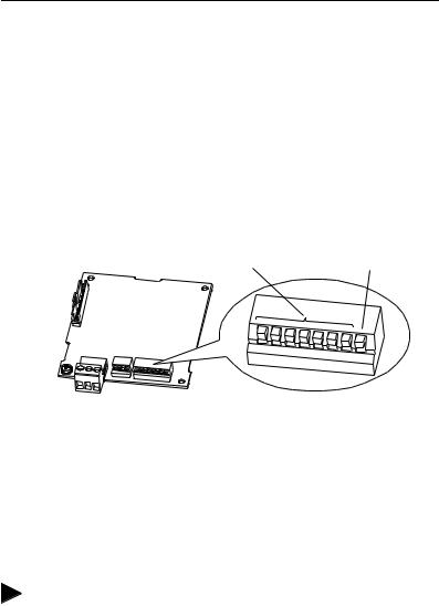
Setting the TERM, -BIAS, and +BIAS Switches
The adapter’s TERM, -BIAS, and +BIAS switches (Figure 2.2) are used to turn on/off its built-in termination resistor and bias resistors.
Figure 2.2 Setting the TERM, -BIAS, and +BIAS Switches
-BIAS Switch (SW2) |
+BIAS Switch (SW3) |
TERM Switch (SW1)
1
RSRV Switch (SW4)
Reserved for future use
2 |
3 |
4 |
UP = OFF
Switches |
Description |
Default |
SW1 |
Turns on/off the termination resistor |
Up (Off) |
SW2 |
Turns on/off the -bias resistor |
Up (Off) |
SW3 |
Turns on/off the +bias resistor |
Up (Off) |
SW4 |
Reserved (not used) |
— |
Since nodes on a BACnet MS/TP network are typically a mix of Allen-Bradley PowerFlex drives and other brands of building automation products, the network node locations for the PowerFlex drives will determine how their adapter’s TERM, -BIAS, and +BIAS switches should be set.
Installing the Adapter |
2-5 |
|
|
Network with PowerFlex Drives at Starting and/or Ending Nodes
For a network with PowerFlex drives at the starting and/or ending nodes (Figure 2.3), set their 22-COMM-B adapter’s TERM, -BIAS, and +BIAS switches to the “Down” (On) position. All other PowerFlex drive network nodes must have these switches set to the “Up” (Off) position.
Figure 2.3 Example Network with PowerFlex Drives at Starting and/or Ending Nodes
Node 1 |
|
Node n |
(Starting Node) |
Node 2 Node 3 Node 4 |
(Ending Node) |
■ ■ ■
BACnet MS/TP Network
22-COMM-B Adapter Settings for TERM, -BIAS, and +BIAS Switches
"Down" (On) Positions |
"Up" (Off) Positions |
"Down" (On) Positions |
Network with PowerFlex Drives at Other Nodes
For a network with PowerFlex drives at other node locations—not starting and/or ending nodes (Figure 2.4), set their 22-COMM-B adapter’s TERM, -BIAS, and +BIAS switches to the “Up” (Off) position. In this network scenario, other brands of building automation products at the starting and/or ending nodes require appropriate termination and bias resistors. Refer to their documentation for details.
Figure 2.4 Example Network with PowerFlex Drives at Other Nodes
Node 1 |
PowerFlex 4-Class Drives |
Node n |
(Starting Node) |
Node 2 Node 3 Node 4 |
(Ending Node) |
|
|
|
Other Brand |
|
Other Brand |
Building Automation |
|
Building Automation |
Product |
|
Product |
|
|
■ ■ ■ |
BACnet MS/TP Network |
Requires |
|
|
|
|
Requires |
|
Termination and |
|
Bias Resistors |
|
Termination and |
|
|
22-COMM-B Settings |
|
|
Bias Resistors |
|
|
|
for TERM, -BIAS, and |
|
+BIAS Switches
"Up" (Off) Positions
2-6 Installing the Adapter
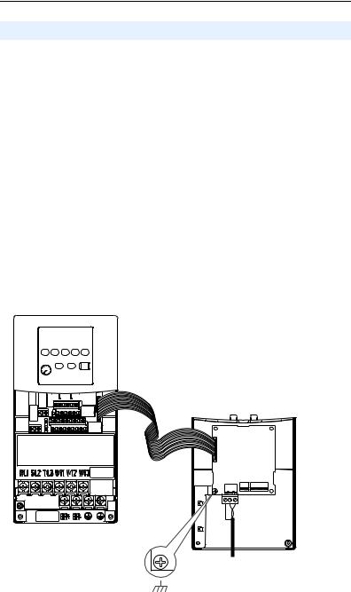
Connecting the Adapter to the Drive
PowerFlex 40 Frames B and C, and PowerFlex 400 Frame C
1.Remove power from the drive, and remove the drive cover.
2.Use static control precautions.
3.Mount the adapter on the required special drive cover (ordered separately; see Figure 2.5 for part numbers).
•Frame B: Do not use the adapter screw; snap the adapter in place.
•Frame C: Use the adapter screw to secure the adapter to the cover.
Important: To properly ground the adapter in Frame B drives, install the special drive cover onto the drive using both cover fasteners. To ground the adapter in Frame C drives, tighten the adapter’s lower left screw (see Figure 2.5). In either case, tighten the screw(s) to the recommended torque (0.9 N•m / 8.0 lb•in).
Figure 2.5 Mounting and Grounding the Adapter – PowerFlex 40 Frames B and C, and PowerFlex 400 Frame C
Adapter Mounted on Back of Required Special Drive Cover (Frame C cover shown)
PowerFlex 40 Frame B -- Part Number 22B-CCB
PowerFlex 40 Frame C -- Part Number 22B-CCC
PowerFlex 400 Frame C -- Part Number 22C-CCC
PowerFlex 40 Drive (Frame C
shown with cover removed)
0.9 N•m
(8.0 lb•in)
Ground for Frame C Drives
NOTE: For Frame B drives, the lower left adapter screw does not ground the adapter. To ground the adapter, install the special drive cover onto the drive using both cover fasteners.
Loading...