


20-750-ENETR
Table of contents
 Loading...
User Manual
PowerFlex 20-750-ENETR Dual-port EtherNet/IP Option
Module
Firmware Revision Number 1.xxx
Important User Information
IMPORTANT
Solid-state equipment has operational characteristics differing from those of electromechanical equipment. Safety
Guidelines for the Application, Installation and Maintenance of Solid State Controls (publication SGI-1.1
your local Rockwell Automation® sales office or online at http://www.rockwellautomation.com/literature/
important differences between solid-state equipment and hard-wired electromechanical devices. Because of this difference,
and also because of the wide variety of uses for solid-state equipment, all persons responsible for applying this equipment
must satisfy themselves that each intended application of this equipment is acceptable.
In no event will Rockwell Automation, Inc. be responsible or liable for indirect or consequential damages resulting from the
use or application of this equipment.
The examples and diagrams in this manual are included solely for illustrative purposes. Because of the many variables and
requirements associated with any particular installation, Rockwell Automation, Inc. cannot assume responsibility or
liability for actual use based on the examples and diagrams.
No patent liability is assumed by Rockwell Automation, Inc. with respect to use of information, circuits, equipment, or
software described in this manual.
Reproduction of the contents of this manual, in whole or in part, without written permission of Rockwell Automation,
Inc., is prohibited.
Throughout this manual, when necessary, we use notes to make you aware of safety considerations.
available from
) describes some
WARNING: Identifies information about practices or circumstances that can cause an explosion in a hazardous environment,
which may lead to personal injury or death, property damage, or economic loss.
ATTENTION: Identifies information about practices or circumstances that can lead to personal injury or death, property
damage, or economic loss. Attentions help you identify a hazard, avoid a hazard, and recognize the consequence.
SHOCK HAZARD: Labels may be on or inside the equipment, for example, a drive or motor, to alert people that dangerous
voltage may be present.
BURN HAZARD: Labels may be on or inside the equipment, for example, a drive or motor, to alert people that surfaces may
reach dangerous temperatures.
Identifies information that is critical for successful application and understanding of the product.
Allen-Bradley, Rockwell Software, Rockwell Automation, TechConnect, PowerFlex, DriveExplorer, DriveTools, DriveExecutive, RSLinx, RSLogi x, ControlLogix, P LC-5, SLC, and MicroL ogix are trademarks of Roc kwell
Automation, Inc.
Trademarks not belonging to Rockwell Automation are property of their respective companies.

Table of Contents
Preface
Getting Started
Installing the Option Module
Conventions Used in This Manual . . . . . . . . . . . . . . . . . . . . . . . . . . . . . . . . . 7
Rockwell Automation Support . . . . . . . . . . . . . . . . . . . . . . . . . . . . . . . . . . . . . 7
Additional Resources . . . . . . . . . . . . . . . . . . . . . . . . . . . . . . . . . . . . . . . . . . . . . . 8
Chapter 1
Components. . . . . . . . . . . . . . . . . . . . . . . . . . . . . . . . . . . . . . . . . . . . . . . . . . . . . . 9
Features . . . . . . . . . . . . . . . . . . . . . . . . . . . . . . . . . . . . . . . . . . . . . . . . . . . . . . . . . 10
Option Module Operating Modes . . . . . . . . . . . . . . . . . . . . . . . . . . . . . . . . . 11
Understanding Parameter Types. . . . . . . . . . . . . . . . . . . . . . . . . . . . . . . . . . . 12
Compatible Products . . . . . . . . . . . . . . . . . . . . . . . . . . . . . . . . . . . . . . . . . . . . . 13
Required Equipment . . . . . . . . . . . . . . . . . . . . . . . . . . . . . . . . . . . . . . . . . . . . . 13
Safety Precautions . . . . . . . . . . . . . . . . . . . . . . . . . . . . . . . . . . . . . . . . . . . . . . . . 14
Quick Start . . . . . . . . . . . . . . . . . . . . . . . . . . . . . . . . . . . . . . . . . . . . . . . . . . . . . . 15
Chapter 2
Preparing for an Installation. . . . . . . . . . . . . . . . . . . . . . . . . . . . . . . . . . . . . . . 17
Setting the Operating Mode. . . . . . . . . . . . . . . . . . . . . . . . . . . . . . . . . . . . . . . 19
Setting the Node Address . . . . . . . . . . . . . . . . . . . . . . . . . . . . . . . . . . . . . . . . . 20
Connecting the Option Module to the Drive . . . . . . . . . . . . . . . . . . . . . . . 22
Connecting the Option Module to the Network. . . . . . . . . . . . . . . . . . . . 23
Applying Power . . . . . . . . . . . . . . . . . . . . . . . . . . . . . . . . . . . . . . . . . . . . . . . . . . 26
Commissioning the Option Module . . . . . . . . . . . . . . . . . . . . . . . . . . . . . . . 30
Configuring the Option Module
Configuring the I/O
Chapter 3
Configuration Tools. . . . . . . . . . . . . . . . . . . . . . . . . . . . . . . . . . . . . . . . . . . . . . 31
Using the PowerFlex 20-HIM-A6 or 20-HIM-C6S HIM
to Access Parameters. . . . . . . . . . . . . . . . . . . . . . . . . . . . . . . . . . . . . . . . . . . 32
Setting the Option Module Node Address. . . . . . . . . . . . . . . . . . . . . . . . . . 32
Setting the Data Rate . . . . . . . . . . . . . . . . . . . . . . . . . . . . . . . . . . . . . . . . . . . . . 38
Selecting Master-Slave or Peer-to-Peer Hierarchy
(Adapter mode only) . . . . . . . . . . . . . . . . . . . . . . . . . . . . . . . . . . . . . . . . . . 39
Setting a Fault Action (Adapter mode only) . . . . . . . . . . . . . . . . . . . . . . . . 46
Setting Web Page Access. . . . . . . . . . . . . . . . . . . . . . . . . . . . . . . . . . . . . . . . . . 48
Resetting the Option Module . . . . . . . . . . . . . . . . . . . . . . . . . . . . . . . . . . . . . 49
Restoring Option Module Parameters to Factory Defaults . . . . . . . . . . . 50
Viewing the Option Module Status Using Parameters . . . . . . . . . . . . . . . 51
Updating the Option Module Firmware . . . . . . . . . . . . . . . . . . . . . . . . . . . 52
Chapter 4
Using RSLinx Classic Software . . . . . . . . . . . . . . . . . . . . . . . . . . . . . . . . . . . . 53
Uploading the Electronic Data Sheet (EDS) File . . . . . . . . . . . . . . . . . . . . 54
ControlLogix Controller Example (Adapter mode only). . . . . . . . . . . . . 54
Rockwell Automation Publication 750COM-UM008A-EN-P - July 2012 3

Table of Contents
Chapter 5
Using the I/O
(Adapter mode only)
Using Explicit Messaging
(Adapter mode only)
Troubleshooting
About I/O Messaging . . . . . . . . . . . . . . . . . . . . . . . . . . . . . . . . . . . . . . . . . . . . 87
Understanding the I/O Image. . . . . . . . . . . . . . . . . . . . . . . . . . . . . . . . . . . . . 88
Using Logic Command/Status . . . . . . . . . . . . . . . . . . . . . . . . . . . . . . . . . . . . 89
Using Reference/Feedback . . . . . . . . . . . . . . . . . . . . . . . . . . . . . . . . . . . . . . . . 89
Using Datalinks . . . . . . . . . . . . . . . . . . . . . . . . . . . . . . . . . . . . . . . . . . . . . . . . . . 90
Example Ladder Logic Program Information . . . . . . . . . . . . . . . . . . . . . . . 91
ControlLogix Controller Example . . . . . . . . . . . . . . . . . . . . . . . . . . . . . . . . . 92
Chapter 6
About Explicit Messaging . . . . . . . . . . . . . . . . . . . . . . . . . . . . . . . . . . . . . . . . . 99
Performing Explicit Messaging . . . . . . . . . . . . . . . . . . . . . . . . . . . . . . . . . . . 100
ControlLogix Controller Examples . . . . . . . . . . . . . . . . . . . . . . . . . . . . . . . 101
Chapter 7
Understanding the Status Indicators . . . . . . . . . . . . . . . . . . . . . . . . . . . . . . 113
Indications for Adapter Mode Operation . . . . . . . . . . . . . . . . . . . . . . . . . 114
Indications for Tap Mode Operation . . . . . . . . . . . . . . . . . . . . . . . . . . . . . 116
Viewing Option Module Diagnostic Items . . . . . . . . . . . . . . . . . . . . . . . . 118
Viewing and Clearing Events . . . . . . . . . . . . . . . . . . . . . . . . . . . . . . . . . . . . . 122
Viewing Option Module Web Pages
Specifications
Option Module Parameters
Chapter 8
Enabling the Option Module Web Pages . . . . . . . . . . . . . . . . . . . . . . . . . . 125
Viewing Web Pages in Adapter Mode . . . . . . . . . . . . . . . . . . . . . . . . . . . . . 125
Adapter Mode Process Display Pop-up Dialog Box. . . . . . . . . . . . . . . . . 128
Adapter Mode TCP/IP Configuration Web Page. . . . . . . . . . . . . . . . . . 129
Adapter Mode Configure E-mail Notification Web Page . . . . . . . . . . . 130
Adapter Mode Device Information Pages. . . . . . . . . . . . . . . . . . . . . . . . . . 133
Viewing Web Pages in Tap Mode. . . . . . . . . . . . . . . . . . . . . . . . . . . . . . . . . 136
Appendix A
Communication . . . . . . . . . . . . . . . . . . . . . . . . . . . . . . . . . . . . . . . . . . . . . . . . 137
Electrical . . . . . . . . . . . . . . . . . . . . . . . . . . . . . . . . . . . . . . . . . . . . . . . . . . . . . . . 138
Mechanical . . . . . . . . . . . . . . . . . . . . . . . . . . . . . . . . . . . . . . . . . . . . . . . . . . . . . 138
Environmental . . . . . . . . . . . . . . . . . . . . . . . . . . . . . . . . . . . . . . . . . . . . . . . . . . 138
Regulatory Compliance. . . . . . . . . . . . . . . . . . . . . . . . . . . . . . . . . . . . . . . . . . 138
Appendix B
Parameter Types . . . . . . . . . . . . . . . . . . . . . . . . . . . . . . . . . . . . . . . . . . . . . . . . 139
About Parameter Numbers. . . . . . . . . . . . . . . . . . . . . . . . . . . . . . . . . . . . . . . 140
How Parameters Are Organized . . . . . . . . . . . . . . . . . . . . . . . . . . . . . . . . . . 140
Parameters for Adapter Mode Operation. . . . . . . . . . . . . . . . . . . . . . . . . . 140
Parameters for Tap Mode Operation. . . . . . . . . . . . . . . . . . . . . . . . . . . . . . 150
4 Rockwell Automation Publication 750COM-UM008A-EN-P - July 2012

Appendix C
Table of Contents
EtherNet/IP Objects
(Adapter mode only)
Logic Command/Status Words:
PowerFlex 750-Series Drives
Supported Data Types . . . . . . . . . . . . . . . . . . . . . . . . . . . . . . . . . . . . . . . . . . . 153
Identity Object. . . . . . . . . . . . . . . . . . . . . . . . . . . . . . . . . . . . . . . . . . . . . . . . . . 154
Assembly Object . . . . . . . . . . . . . . . . . . . . . . . . . . . . . . . . . . . . . . . . . . . . . . . . 155
Register Object. . . . . . . . . . . . . . . . . . . . . . . . . . . . . . . . . . . . . . . . . . . . . . . . . . 156
PCCC Object . . . . . . . . . . . . . . . . . . . . . . . . . . . . . . . . . . . . . . . . . . . . . . . . . . 157
DPI Device Object . . . . . . . . . . . . . . . . . . . . . . . . . . . . . . . . . . . . . . . . . . . . . . 160
DPI Parameter Object . . . . . . . . . . . . . . . . . . . . . . . . . . . . . . . . . . . . . . . . . . . 163
DPI Fault Object. . . . . . . . . . . . . . . . . . . . . . . . . . . . . . . . . . . . . . . . . . . . . . . . 169
DPI Alarm Object. . . . . . . . . . . . . . . . . . . . . . . . . . . . . . . . . . . . . . . . . . . . . . . 171
DPI Diagnostic Object . . . . . . . . . . . . . . . . . . . . . . . . . . . . . . . . . . . . . . . . . . 173
DPI Time Object . . . . . . . . . . . . . . . . . . . . . . . . . . . . . . . . . . . . . . . . . . . . . . . 175
Host DPI Parameter Object. . . . . . . . . . . . . . . . . . . . . . . . . . . . . . . . . . . . . . 177
TCP/IP Interface Object . . . . . . . . . . . . . . . . . . . . . . . . . . . . . . . . . . . . . . . . 183
Ethernet Link Object. . . . . . . . . . . . . . . . . . . . . . . . . . . . . . . . . . . . . . . . . . . . 185
Appendix D
Logic Command Word . . . . . . . . . . . . . . . . . . . . . . . . . . . . . . . . . . . . . . . . . . 187
Logic Status Word . . . . . . . . . . . . . . . . . . . . . . . . . . . . . . . . . . . . . . . . . . . . . . 188
Glossary
Index
Rockwell Automation Publication 750COM-UM008A-EN-P - July 2012 5

Table of Contents
Notes:
6 Rockwell Automation Publication 750COM-UM008A-EN-P - July 2012

Preface
This manual provides information about the 20-750-ENETR Dual-port
EtherNet/IP Option Module for network communication and how to use the
module with PowerFlex 750-Series drives.
Conventions Used in This Manual
Rockwell Automation Support
The following conventions are used throughout this manual:
• Parameter names are shown in the format Device Parameter xx - [*] or
Host Parameter xx - [*]. The xx represents the parameter number. The *
represents the parameter name—for example, Device Parameter 01 -
[Operating Mode].
• The firmware revision number (FRN) is displayed as FRN X.xxx, where
‘X’ is the major revision number and ‘xxx’ is the minor revision number.
• For the screen captures in this manual, the following software was used:
– RSLinx Classic software, version 2.52
– RSLogix 5000 software, version 16.00 and, for Automatic Device
Configuration information, version 20.00
Different versions of the software may differ in appearance and
procedures.
Rockwell Automation offers support services worldwide, with over 75 sales and
support offices, over 500 authorized distributors, and over 250 authorized
systems integrators located through the United States alone. In addition,
Rockwell Automation representatives are in every major country in the world.
Local Product Support
Contact your local Rockwell Automation representative for the following:
• Sales and order support
• Product technical training
• Wa r r a nt y s up po rt
• Support service agreements
Technical Product Assistance
For technical assistance, please review the information in Chapter 7,
Troubleshooting, first. If you still have problems, then access the Allen-Bradley
Technical Support website at http://www.ab.com/support/abdrives
Rockwell Automation.
Rockwell Automation Publication 750COM-UM008A-EN-P - July 2012 7
or contact

Preface
Additional Resources
Resource Description
Network Communication Option Module Installation Instructions, publication 750COM-IN002 Information on the installation of PowerFlex® 750-Series Network
EtherNet/IP Media Planning and Installation Manual, ODVA publication 148
EtherNet/IP Network Infrastructure Guidelines, ODVA publication 35
Ethernet Design Considerations Reference Manual, publication ENET-RM002
EtherNet/IP Embedded Switch Technology - Linear and Device-level Ring Topologies, publication
ENET-AP005
DriveExplorer website http://www.ab.com/drives/driveexplorer, and online help
DriveExecutive website http://www.ab.com/drives/drivetools
PowerFlex 750-Series Drive Installation Instructions, publication 750-IN001 Information on installing, programming, and technical data of PowerFlex 750-
PowerFlex 750-Series Drive Programming Manual, publication 750-PM001
PowerFlex 750-Series Drive Technical Data, publication 750-TD001
PowerFlex 20-HIM-A6/-C6S HIM (Human Interface Module) User Manual, publication 20HIM-UM001 Information on the installation and use of PowerFlex 20-HIM-A6 or 20-HIM-
Getting Results with RSLinx Guide, publication LINX-GR001, and online help
RSLogix 5000 PIDE Autotuner Getting Results Guide, publication PIDE-GR001
EtherNet/IP Modules in Logix5000 Control Systems User Manual, publication ENET-UM001 Information on using the ControlLogix® 1756-EN2TR or 1756-EN3TR EtherNet/
Controller Examples for EtherNet/IP Network Communications with PowerFlex 750-Series Drives,
publication 750COM-AT001
These documents contain additional information concerning related products
from Rockwell Automation.
Communication Modules.
(1)
(1)
, and online help
(2)
(2)
(2)
, and online help
Information on the planning, installation, and techniques used to implement
an EtherNet/IP network.
Information on using the DriveExplorer™ software tool.
Information on using the DriveExecutive™ software tool.
Series drives.
C6S HIMs.
Information on using RSLinx® Classic software.
(2)
Information on using the RSLogix™ 5000 software tool.
IP communication modules with your Logix5000 controller and
communicating with various devices on the EtherNet/IP network.
Information on using PLC-5®, SLC™ 500, and MicroLogix™ 1100/1400
controllers with PowerFlex 750-Series drives that are equipped with a
20-750-ENETR Dual-port EtherNet/IP option module or embedded EtherNet/
IP adapter (PowerFlex 755 drive only).
(1) Use this link to the ODVA EtherNet/IP library: http://od va.org/Home/ODVATECHNOLOGIES/EtherNetIP/EtherNetIPLibrary/tabid/76/Default.aspx.
(2) The online help is installed with the software.
You can view or download publications at http://
www.rockwellautomation.com/literature. To order paper copies of technical
documentation, contact your local Allen-Bradley® distributor or Rockwell
Automation sales representative.
To find your local Rockwell Automation distributor or sales representative, visit
www.rockwellautomation.com/locations
For information, such as firmware updates or answers to drive-related questions,
go to the Drives Service & Support website at http://www.ab.com/support/
abdrives and click the Downloads or Knowledgebase link.
.
8 Rockwell Automation Publication 750COM-UM008A-EN-P - July 2012
Chapter 1
➊
➋
➌
➍
➎
➏
0
5
4
9
3
8
2
7
1
6
0
5
4
9
3
8
2
7
1
6
0
5
4
9
3
8
2
7
1
6
MODE
ADPTR
TAP
J4
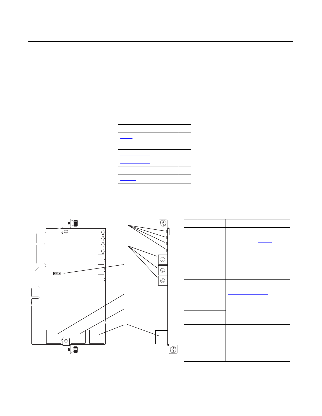
Item Part Description
➊
Status Indicators Four status indicators that indicate the
status of the option module and network
communication. See Chapter 7,
Troubleshooting.
➋
Node Address
Switches
Sets the network node address of the
option module when not using:
• A BOOTP or DHCP server
• Option module parameters
See Setting the Node Address
on page 20.
➌
Operating Mode
Jumper (J4)
Selects the mode in which the option
module operates. See Setting the
Operating Mode on page 19.
➍
ENET1 Network
Port
RJ-45 connector for the Ethernet network
cable. The connector is CAT-5 compliant
to ensure reliable data transfer on
100Base-TX Ethernet connections. Either
port may be used in Adapter mode.
➎
ENET2 Network
Port
➏
ENET3 (DEVICE)
Port (PowerFlex
755 only)
RJ-45 connector to connect the shor t
Ethernet cable (provided with the option
module) to the Ethernet port on the
PowerFlex 755 drive embedded EtherNet/
IP adapter. This is intended for ‘Integrated
Motion on the EtherNet/IP network’ data
transfer.
Component Side View Top View
Getting Started
The 20-750-ENETR Option Module is intended for installation into a
PowerFlex 750-Series drive and is used for network communication.
Top ic Pa ge
Components
Featu res
Option Module Operating Modes
Compatible Produ cts
Required Equipment
Safety Precautions 14
Quick Start 15
9
10
11
13
13
Components
Rockwell Automation Publication 750COM-UM008A-EN-P - July 2012 9

Chapter 1 Getting Started
Features
The features of the option module include the following:
• Adapter or Tap mode of operation that is selected by using the Operating
Mode Jumper (J4). In Adapter mode (default), the option module
operates as a network communication adapter supporting star, linear or
device-level ring (DLR) network topologies. In Tap mode—only intended
for use with PowerFlex 755 drives—the option module uses ENET3
(DEVICE) port as a connection point to transfer ‘Integrated Motion on
the EtherNet/IP network’ data to the PowerFlex 755 drive’s embedded
EtherNet/IP adapter.
• Industrial Ethernet switch, and ENET1 and ENET2 network ports that
provide connections for EtherNet/IP star, linear, or device-level ring
(DLR) network topologies.
• ENET3 (DEVICE) port—for use with only PowerFlex 755 drives—that
supports the transfer of ‘Integrated Motion on the EtherNet/IP network’
data for that drive.
• Embedded electronic data sheet (EDS) files for PowerFlex 750-Series
drives that eliminate the need to download an EDS file from the Rockwell
Automation website. Instead, the EDS file is uploaded from the option
module by using RSLinx software.
• Automatic Device Configuration (ADC), which is an ‘RSLogix 5000
software, version 20 or later, feature’ that supports the automatic
download of configuration data. This occurs after the Logix controller
establishes an EtherNet/IP network connection to a PowerFlex 750-Series
drive (firmware revision 4.001 or later) and its associated peripherals.
• Captive screws to secure and ground the module to the drive.
• Switches to set a network node address before applying power to the
drive—or you can disable the switches and use a BOOTP server, a
Dynamic Host Configuration Protocol (DHCP) server, or option module
parameters to configure the IP address.
• Compatibility with various configuration tools to configure the option
module and host drive. The tools include the enhanced PowerFlex 7-Class
HIM (catalog number 20-HIM-A6 or 20-HIM-C6S) on the drive, and
drive-configuration software, such as DriveExplorer software, version 6.01
or later, or DriveExecutive software, version 5.01 or later.
• Status indicators that report the status of the option module and network
communication. They are visible when the drive cover is removed.
• Parameter-configured 32-bit Datalinks in the I/O to meet application
requirements (16 Datalinks to write data from the network to the drive,
and 16 Datalinks to read data to the network from the drive).
• Explicit Messaging support.
10 Rockwell Automation Publication 750COM-UM008A-EN-P - July 2012

TIP
Getting Started Chapter 1
• Master-Slave or Peer-to-Peer hierarchy that can be configured to transmit
data to and from a controller or another PowerFlex 750-Series drive on the
network by using another 20-750-ENETR option module or the
embedded EtherNet/IP adapter in a PowerFlex 755 drive.
• Supports ‘Integrated Motion on the EtherNet/IP network’ operation (Tap
mode only) for only the PowerFlex 755 drive, firmware revision 2.003 or
later. For details to set up ‘Integrated Motion on the EtherNet/IP network’
operation, see Integrated Motion on the EtherNet/IP Network User
Manual, publication MOTION-UM003
For best reliability in ‘Integrated Motion on the EtherNet/IP network’
applications, we recommend that you always use Rockwell
Automation Cat5e shielded Ethernet cable.
• User-defined fault actions to determine how the option module and its
connected host drive respond to the following:
– I/O messaging communication disruptions (Comm Flt Action)
– Controllers in Idle mode (Idle Flt Action)
– Peer device communication disruptions (Peer Flt Action)
– Explicit messaging disruptions for drive control via PCCC, the CIP
Register Object or the CIP Assembly object (Msg Flt Action)
.
Option Module Operating Modes
• Accessing parameters by their name or their number.
• Web pages, viewed by using a web browser, that show information about
the option module, its host drive, and DPI devices connected to the drive.
Depending on its selected operating mode (Adapter or Tap), the option
module provides a unique set of web pages with different information.
• Configured e-mail messaging (Adapter mode only) to desired addresses
when selected drive faults occur and/or are cleared, and/or when the
option module takes a communication or idle fault action.
• Access to any PowerFlex drive and its connected peripherals on the
network to which the option module is connected.
The option module can be operated in Adapter mode (default) or Tap mode. The
Operating Mode Jumper J4 (item 3 in Figure 1 on page 19
operating mode. If the jumper is missing, the option module operates in the
Adapter mode.
Adapter Mode (default)
) is used to select the
In the Adapter mode, the option module operates as an EtherNet/IP network
communication module. With its EtherNet/IP embedded switch technology and
ENET1 and ENET2 network ports, the option module enables the drive to be
Rockwell Automation Publication 750COM-UM008A-EN-P - July 2012 11

Chapter 1 Getting Started
IMPORTANT
IMPORTANT
used in a linear or device-level ring (DLR) network topology. When using a star
network topology, either the ENET1 or ENET2 network port may be used. In
Adapter mode, the ‘Integrated Motion on the EtherNet/IP network’
functionality is not supported.
Tap Mode (only with PowerFlex 755 drives)
In the Tap mode, the option module operates like a gateway and functions similar
to the 1783-ETAP module. By connecting the supplied Ethernet cable between
the option module’s ENET3 network port and the embedded EtherNet/IP
adapter port on the PowerFlex 755 drive, the option module enables the
PowerFlex 755 drive to extend its I/O connection to a linear or device-level ring
(DLR) network topology. This also enables ‘Integrated Motion on the EtherNet/
IP network’ functionality supported by the PowerFlex 755 drive to be used with
these topologies.
Understanding Parameter Types
The option module has two types of parameters:
• Device parameters are used to configure the option module to operate on
the network. Device parameters, when viewed with DriveExplorer or
DriveExecutive software, appear below the 20-750-ENETR listing in the
treeview in a separate Device Parameters folder. When viewed with the
20-HIM-A6 or 20-HIM-C6S HIM, these parameters appear in the DEV
PARA M fol der.
Some Device parameters are not applicable when operating the option
module in Adapter mode while others are not applicable in Tap mode.
Therefore, these non-applicable parameters are labeled ‘Reserved’ in
the Adapter and Tap mode operation parameter tables in Appendix
• Host parameters are used to configure the option module Datalink transfer
and various fault actions with the drive. Host parameters, when viewed
with DriveExplorer or DriveExecutive software, appear below the 20-750ENETR listing in the treeview in a separate Host Parameters folder. When
viewed with the 20-HIM-A6 or 20-HIM-C6S HIM, these parameters
appear in the HOST PARAM folder.
When operating the option module in Tap mode, Host parameters are
not supported.
B.
12 Rockwell Automation Publication 750COM-UM008A-EN-P - July 2012

Getting Started Chapter 1
Compatible Products
Required Equipment
At the time of publication, the option module is compatible with the following:
• PowerFlex 753 drives (all firmware revisions)
• PowerFlex 755 drives (firmware revision 1.010 or later)
(1) When the option module is connected to an incompatible drive, its PORT status indicator will flash orange indicating that it is
not compatible with the drive.
Some of the equipment that is required for use with the option module is shipped
with the module, but some you must supply yourself.
Equipment Shipped with the Option Module
When you unpack the option module, verify that the package includes the
following:
❑ One 20-750-ENETR Dual-port EtherNet/IP Option Module
❑ One short Ethernet cable (spare part catalog number 1585J-M8CBJM-
0M3; for Tap mode use only with PowerFlex 755 drives)
❑ One Network Communication Option Card Installation Instructions,
publication 750COM-IN002
(1)
User-supplied Equipment
To install and configure the option module, you must supply the following:
❑ A small screwdriver
❑ Ethernet cable (for details, see the EtherNet/IP Media Planning and
Installation Manual, ODVA publication 148 available on the ODVA
website at http://odva.org/Home/ODVATECHNOLOGIES/
EtherNetIP/EtherNetIPLibrary/tabid/76/Default.aspx)
❑ Configuration tool, such as the following:
– PowerFlex 20-HIM-A6 or 20-HIM-C6S HIM
– DriveExplorer software, version 6.01 or later
– DriveExecutive standalone software, version 5.01 or later, or bundled
with the DriveTools SP suite, version 5.01 or later
– BOOTP, version 2.1 or later, or DHCP Server for network setup only
❑ Controller configuration software, such as RSLogix 5000 software
❑ A computer connection to the EtherNet/IP network
Rockwell Automation Publication 750COM-UM008A-EN-P - July 2012 13
Chapter 1 Getting Started
Safety Precautions
Please read the following safety precautions carefully.
ATTENTION: Risk of injury or death exists. The PowerFlex drive may contain high
voltages that can cause injury or death. Remove all power from the PowerFlex
drive, and then verify power has been discharged before installing or removing
the option module.
ATTENTION: Risk of injury or equipment damage exists. Only personnel familiar
with drive and power products and the associated machinery should plan or
implement the installation, startup, configuration, and subsequent maintenance
of the drive using the option module. Failure to comply may result in injury and/
or equipment damage.
ATTENTION: Risk of equipment damage exists. The option module contains
electrostatic discharge (ESD) sensitive parts that can be damaged if you do not
follow ESD control procedures. Static control precautions are required when
handling the option module. If you are unfamiliar with static control procedures,
see Guarding Against Electrostatic Damage, publication 8000-4.5.2
ATTENTION: Risk of injury or equipment damage exists. If the option module is
transmitting control I/O to the drive, the drive may fault when you reset the
option module. Determine how your drive will respond before resetting the
module.
.
ATTENTION: Risk of injury or equipment damage exists. Host Parameters 33 [Comm Flt Action], 34 - [Idle Flt Action], 35 - [Peer Flt Action], and 36 [Msg Flt Action] let you determine the action of the option module and
connected drive if I/O communication is disrupted, the controller is idle, Peer I/O
is disrupted, or explicit messaging for drive control is disrupted. By default, these
parameters fault the drive. You may configure these parameters so that the drive
continues to run, however, precautions should be taken to verify that the settings
of these parameters do not create a risk of injury or equipment damage. When
commissioning the drive, verify that your system responds correctly to various
situations (for example, a disconnected cable or a controller in idle state).
ATTENTION: Risk of injury or equipment damage exists. When a system is
configured for the first time, there may be unintended or incorrect machine
motion. Disconnect the motor from the machine or process during initial system
testing.
ATTENTION: Risk of injury or equipment damage exists. The examples in this
publication are intended solely for purposes of example. There are many
variables and requirements with any application. Rockwell Automation does not
assume responsibility or liability (to include intellectual property liability) for
actual use of the examples shown in this publication.
14 Rockwell Automation Publication 750COM-UM008A-EN-P - July 2012

Getting Started Chapter 1
Quick Start
This section is provided to help experienced users quickly start using the option
module in Adapter mode or Tap mode. If you are unsure how to complete a step,
refer to the referenced chapter.
Adapter Mode of Operation
Step Action See
1 Review the safety precautions for the option module. Throughout this manual
2 Verify that the PowerFlex drive is properly installed. PowerFlex 750-Series AC Drive
3 Set the option module IP address.
a. When using the option module node address switches, set the IP
address now and proceed with step 4. When using a DHCP or
BOOTP server, or option module parameters instead to set the IP
address, first perform step 3b and all of step 4. Then proceed with
step 5.
b. Verify that the PowerFlex drive is not powered.
4 Install the option module.
a. Insert the option module in drive Port 4, 5, or 6. Use the captive
crews to secure and ground the option module to the drive.
b. Connect the option module to the network by using an Ethernet
cable.
5 Apply power to the option module.
a. The option module receives power from the drive. Verify that the
option module is installed correctly and then apply power to the
drive. The status indicators should be green. If they flash red, there
is a problem. See Chapter 7
b. Configure and verify key drive parameters.
6 Configure the option module for your application.
Set option module parameters for the following functions as required by
your application:
• IP address, subnet mask, and gateway address (only when not using
option module node address switches)
• Data rate
• I/O configuration
• Master-Slave or Peer-to-Peer hierarchy
• Fault actions
• Web enable and features
7 Configure the controller to communicate with the option module.
Use a controller configuration tool such as RSLogix software to configure
the master on the network to recognize the option module and drive.
8 Create a ladder logic program.
Use a controller configuration tool such as RSLogix software to create a
ladder logic program that enables you to do the following:
• Control the option module and connected drive by using I/O.
• Monitor or configure the drive by using Explicit messages.
, Troubleshooting.
Installation Instructions,
publication 750-IN001
,
Chapter 2
Installing the Option Module
Network Communication Option
Card Installation Instructions,
publication 750COM-IN002
,
Chapter 2
Installing the Option Module
,
Chapter 2
Installing the Option Module
,
Chapter 3
Configuring the Option Module
Chapter 4
,
Configuring the I/O
,
Chapter 5
Using the I/O (Adapter mode
only)
,
Chapter 6
Using Explicit Messaging
(Adapter mode only)
and
Rockwell Automation Publication 750COM-UM008A-EN-P - July 2012 15

Chapter 1 Getting Started
Tap Mode of Operation (only with PowerFlex 755 drives)
Step Action See
1 Review the safety precautions for the option module. Throughout this manual
2 Verify that the PowerFlex drive is properly installed. PowerFlex 750-Series AC Drive
3 Set the option module IP address.
a. When using the option module node address switches, set the IP
address now and proceed with step 4. When using a DHCP server,
BOOTP server, or option module parameters to set the IP address,
first perform step 3b and all of step 4. Then proceed with step 5.
b. Verify that the PowerFlex drive is not powered.
4 Install the option module.
a. Insert the option module in only PowerFlex 755 drive Port 4 or 5.
Use the captive crews to secure and ground the option module to
the drive.
b. Connect the option module to the network by using an Ethernet
cable.
5 Apply power to the option module.
a. The option module receives power from the drive. Verify that the
option module is installed correctly and then apply power to the
drive. The status indicators should be green. If they flash red, there
is a problem. See Chapter 7
b. Configure and verify key drive parameters.
6 Configure the option module for your application.
Set option module parameters for the following functions as required by
your application:
• IP address, subnet mask, and gateway address (only when not using
option module node address switches)
• Data rate
• Web enable and features
7 Set (or verify) the IP address for the embedded EtherNet/IP adapter in
the PowerFlex 755 drive.
, Troubleshooting.
Installation Instructions,
publication 750-IN001
Chapter 2,
Installing the Option Module
Network Communication Option
Card Installation Instructions,
publication 750COM-IN002
Chapter 2,
Installing the Option Module
,
Chapter 2
Installing the Option Module
,
Chapter 3
Configuring the Option Module
PowerFlex 755 Drive Embedded
EtherNet/IP Adapter User Manual,
publication 750COM-UM001
and
16 Rockwell Automation Publication 750COM-UM008A-EN-P - July 2012

Chapter 2
Installing the Option Module
This chapter provides instructions for installing the option module in a
PowerFlex 750-Series drive.
Top ic Pa ge
Preparing for an Installation 17
Setting the Operating Mode
Setting the Node Address
Connecting the Option Module to the Drive
Connecting the Option Module to the Network
Applying Power 26
Commissioning the Option Module 30
19
20
22
23
Preparing for an Installation
Before installing the option module, do the following:
• Make sure the Ethernet switch is the correct type. A “managed” switch that
supports IGMP snooping is usually recommended. An “unmanaged”
switch can be used instead if RSLogix 5000 software, version 18.00 or
later, is used and all devices on the network are configured for “unicast”
I/O. For more details, see the following documents:
– EtherNet/IP Media Planning and Installation Manual,
ODVA publication 148
– EtherNet/IP Network Infrastructure Guidelines,
ODVA publication 35
– Ethernet Design Considerations Reference Manual,
publication ENET-RM002
• Understand IGMP Snooping/Ethernet Switches
The option module is a multicast device. In most situations, an IGMP
snooping (managed) switch is required. If more than one or two
EtherNet/IP option modules are connected to the switch, a managed
switch is required—otherwise the drive may fault on a Net IO Timeout
network loss. The option module, RSLogix 5000 software version 18.00
or later, and a ControlLogix or CompactLogix controller will support
unicast. Unicast setup is required when adding the drive to the I/O. When
all option modules are set up as unicast devices, then an IGMP snooping
(managed) switch is not needed.
Rockwell Automation Publication 750COM-UM008A-EN-P - July 2012 17

Chapter 2 Installing the Option Module
IMPORTANT
Much of EtherNet/IP implicit (I/O) messaging uses IP multicast to
distribute I/O control data, which is consistent with the CIP producer/
consumer model. Historically, most switches have treated multicast
packets the same as broadcast packets. That is, all multicast packets are retransmitted to all ports.
IGMP snooping constrains the flooding of multicast traffic by dynamically
configuring switch ports so that multicast traffic is forwarded only to ports
associated with a particular IP multicast group.
Switches that support IGMP snooping (managed switches) ‘learn’ which
ports have devices that are part of a particular multicast group and only
forward the multicast packets to the ports that are part of the multicast
group.
Be careful as to what level of support a switch has of IGMP snooping.
Some layer 2 switches that support IGMP snooping require a router
(which could be a layer 3 switch) to send out IGMP polls to learn what
devices are part of the multicast group. Some layer 2 switches can use
IGMP snooping without a router sending polls. If your control system is a
standalone network or is required to continue performing if the router is
out of service, make sure the switch you are using supports IGMP
snooping without a router being present.
• See Appendix
option module.
A for the number of CIP connections supported by the
• Verify that you have all required equipment. See Required Equipment
page 13.
ATTENTION: Risk of equipment damage exists. The option module contains
electrostatic discharge (ESD) sensitive parts that can be damaged if you do not
follow ESD control procedures. Static control precautions are required when
handling the option module. If you are unfamiliar with static control procedures,
see Guarding Against Electrostatic Damage, publication 8000-4.5.2
The option module has EtherNet/IP embedded switch technology, and ENET1
and ENET2 network ports to connect to a linear or device-level ring (DLR)
network in a single subnet.
You cannot use ENET1 and ENET 2 network ports as two network interface
cards connected to two different subnets.
.
on
18 Rockwell Automation Publication 750COM-UM008A-EN-P - July 2012
Installing the Option Module Chapter 2
TIP
IMPORTANT
MODE
ADPTR
TAP
J4
Adapter Mode
Jumper Position
(default)
Tap Mode
Jumper Position
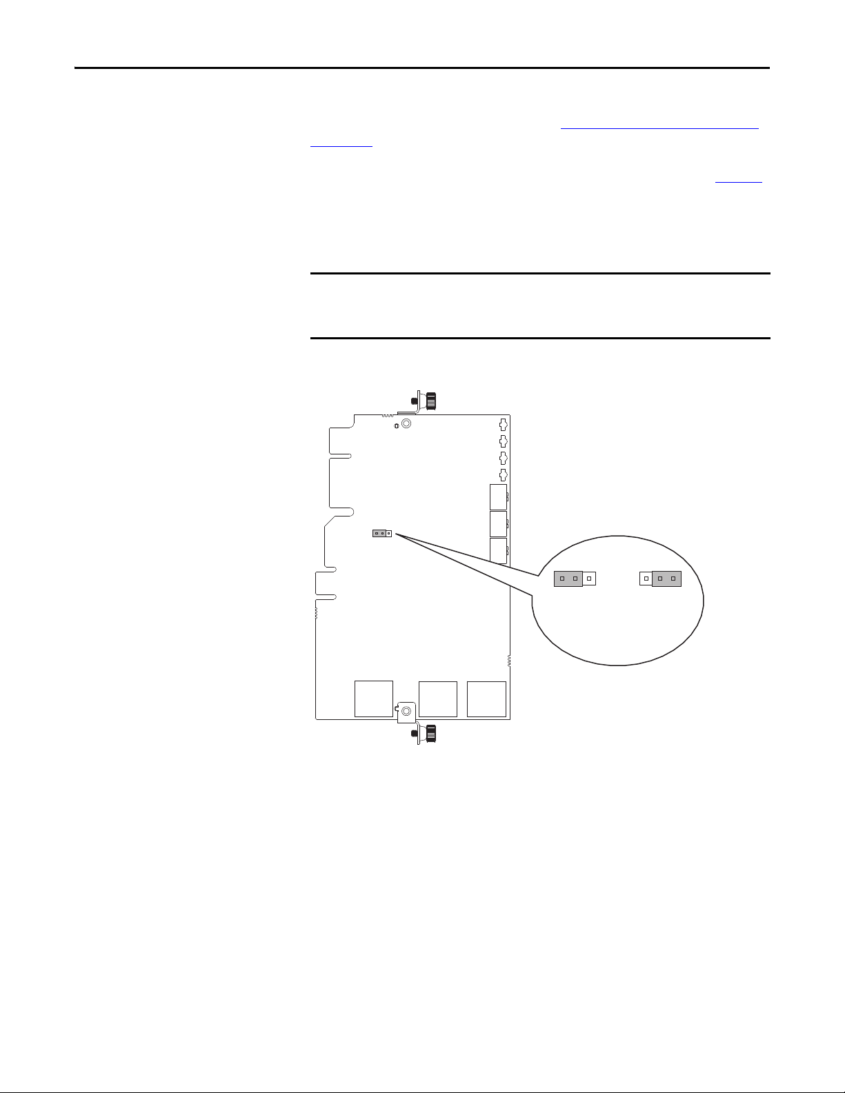
Setting the Operating Mode
The option module can be operated in Adapter mode (default) or Tap mode. For
information about the operating modes, see Option Module Operating Modes
on page 11.
Before installing the option module, set its Operating Mode Jumper J4 (Figure 1
for the desired mode of operation.
If Operating Mode Jumper J4 is missing, the option module operates in the
Adapter mode.
A new jumper setting is recognized only when power is applied to the option
module, or the module is reset. If you change a jumper setting, cycle power to
the drive or reset the module to apply the change.
Figure 1 - Setting Operating Mode Jumper J4
)
Rockwell Automation Publication 750COM-UM008A-EN-P - July 2012 19

Chapter 2 Installing the Option Module
IMPORTANT
IMPORTANT
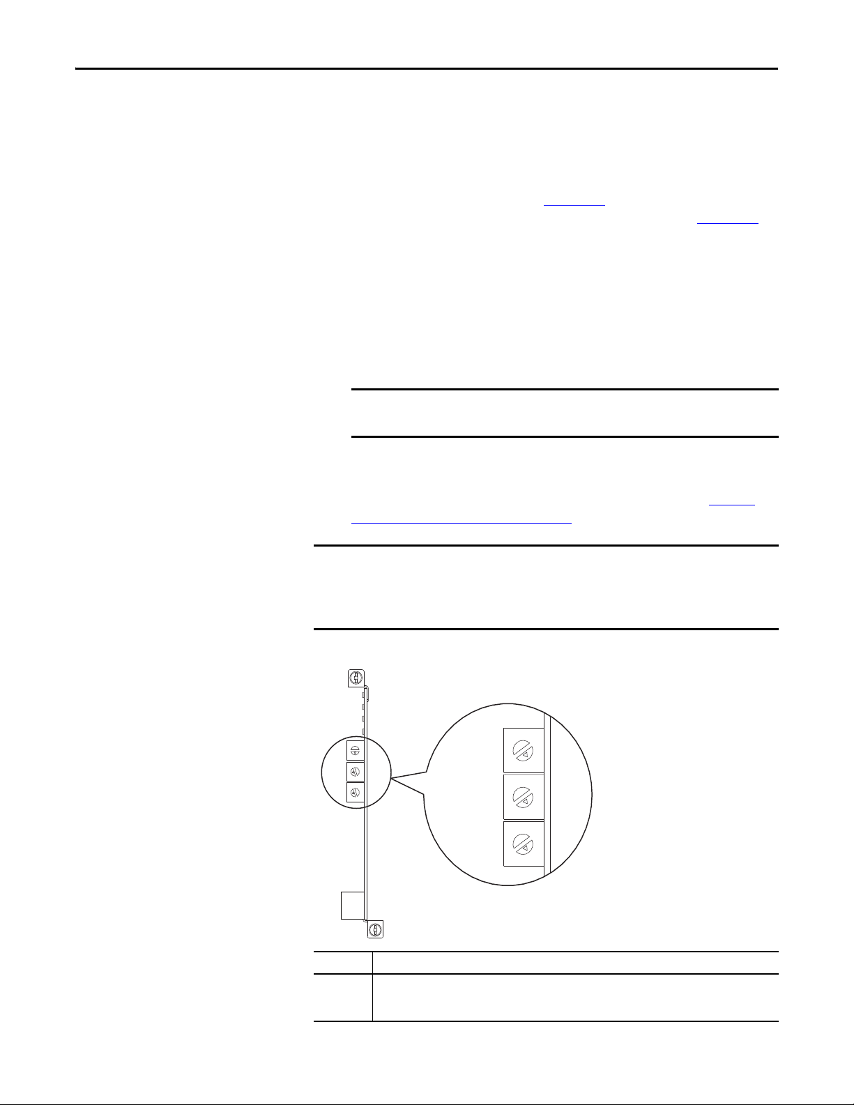
Setting the Node Address
There are four methods for configuring the option module node address:
• Node Address Switches — Use these switches when working on a simple,
isolated network (for example, 192.168.1.xxx) that has other products
with switches to set their IP addresses, does not need to be accessed from
outside the network, and you prefer a simplified node addressing method.
The three rotary switches are read when the drive powers up, and represent
three decimal digits from top to bottom (see Figure 2
address (001…254), the option module will use that value as the lower
octet of its IP address (192.168.1.xxx, where xxx = rotary switch settings),
along with a subnet mask of 255.255.255.0, and a gateway address of
0.0.0.0 when switches are set to 001, or a gateway address of 192.168.1.1
when switches are set from 002…254. Also, the setting for Device
Parameter 05 - [Net Addr Sel] is automatically ignored.
See Figure 2
their related descriptions.
and its accompanying table for all possible switch settings and
When using the Node Address switches, set the network node address
before power is applied because the option module uses the node
address it detects when it first receives power.
). When set to a valid
•Option Module Parameters — Use option module parameters when you
want more flexibility in setting up the network node address, or need to
communicate outside the control network using a gateway. To use
parameters as the source for the IP address, the Node Address switches
must be set to a value other than 001…254 or 888, and Device Param eter
05 - [Net Addr Sel] must be set to “1” (Parameters). The IP address,
subnet mask, and gateway address will then come from the values set using
the associated option module parameters. For details, see Using Option
Module Parameters on page 36.
If parameter values are invalid or the option module was not reset for
the values to take effect, the node address is established by using
DHCP.
•BOOTP — Use BOOTP when you want to configure a temporary IP
address, subnet mask, and gateway address for the option module using a
BOOTP server. To use BOOTP as the source for the IP address, the Node
Address switches must be set to a value other than 001…254 or 888, and
Device Parameter 05 - [Net Addr Sel] must be set to “2” (BOOTP).
Note the option module’s hardware Ethernet Address (MAC) on the
module’s data nameplate label located on the backside of the circuit board,
which will be used in step 7 when configuring the BOOTP server (see
Using a BOOTP or DHCP Server on page 32
for details).
20 Rockwell Automation Publication 750COM-UM008A-EN-P - July 2012
Installing the Option Module Chapter 2
TIP
IMPORTANT
IMPORTANT
Ones
Posit ion
Hundreds
Posit ion
Ten s
Posit ion
If the PowerFlex 750-Series drive is connected to a Stratix 6000 or Stratix
8000 managed Ethernet switch and the drive is set for BOOTP mode, the
“dynamic IP address assignment by port” (Stratix 6000) or “DHCP
persistence” (Stratix 8000) feature will set the IP address for the drive.
For more details, see the Stratix 6000 Ethernet Managed Switch User
Manual, publication 1783-UM001
or the Stratix 8000 and Stratix 8300
Ethernet Managed Switches User Manual, publication 1783-UM003
• DHCP (Dynamic Host Configuration Protocol) — Use DHCP, the
default, when you want additional flexibility and ease-of-use compared to
BOOTP in configuring the IP address, subnet mask, and gateway address
for the option module using a DHCP server. To use DHCP as the source
for the IP address, the Node Address switches must be set to a value other
than 001…254 or 888, and Device Parameter 05 - [Net Addr Sel] must be
set to “3” (DHCP).
When the DHCP lease expires, the option module stops communicating
on the network, requiring a power cycle or option module reset.
Note the option module’s hardware Ethernet Address (MAC) on the
module’s data nameplate label on the backside of the circuit board, which
will be used in step 7 when configuring the DHCP server (see Using a
BOOTP or DHCP Server on page 32 for details).
.
Regardless of the method used to set the option module network node
address, each node on the EtherNet/IP network must have a unique IP address.
To change a node address, you must set the new value and then remove and
reapply power to (or reset) the option module.
Figure 2 - Setting the Node Address Switches
5
6
5
6
4
7
3
8
2
9
1
0
5
6
4
7
3
8
2
9
1
0
5
6
4
7
3
8
2
9
1
0
Settings Description
001…254 The option module will use the Node Address switch settings for the network node address
(192.168.1.xxx, where xxx = rotary switch settings). The value stored in Device Parameter 05 - [Net
Addr Sel] is automatically ignored.
4
7
3
8
2
9
1
0
5
6
4
7
3
8
2
9
1
0
5
6
4
7
3
8
2
9
1
0
Rockwell Automation Publication 750COM-UM008A-EN-P - July 2012 21

Chapter 2 Installing the Option Module
IMPORTANT
IMPORTANT
IMPORTANT
Settings Description
888 Resets the option module network node address to factor y defaults. Thereafter, the drive must be
Any other
setting
The Node Address switch settings can be verified by viewing Diagnostic Item
number 73 (page 120
C6S HIM, DriveExplorer software, or DriveExecutive software. Also, you can
use Device Parameter 06 - [Net Addr Src], a read-only parameter, to verify the
selected setting for Device Parameter 05 - [Net Addr Sel].
powered down, the Node Address switches must be set to a correct value (001…254), and then the
drive must be powered up again to accept the new address.
Disables the Node Address switches, and requires using Device Parameter 05 - [Net Addr Sel] to
select the source for the option module’s network node address:
• 1 = Parameters of the option module
• 2 = BOOTP server
• 3 = DHCP server (default)
or page 122) with a PowerFlex 20-HIM-A6 or 20-HIM-
Connecting the Option Module to the Drive
Remove power from the drive before installing the option module in the drive
control pod.
The option module is connected to the drive differently depending on the mode
in which the option module is operated.
When Operating in Adapter Mode
Install the option module in the PowerFlex 750-Series drive control pod in Port
4, 5 or 6. For more installation details, see the Network Communication Option
Card Installation Instructions, publication 750COM-IN002
option module.
After inserting the option module into drive Port 4, 5 or 6, make sure to tighten
the module screws to the pod mounting bracket to properly ground the
module to the drive. Torque both screws to 0.45…0.67 N•m (4.0…6.0 lb•in).
When Operating in Tap Mode (only with PowerFlex 755 drives)
, provided with the
Install the option module in the PowerFlex 755 drive control pod in only Port 4
or 5. (When operating in Tap mode, drive Port 6 cannot be used.) For more
installation details, see the Network Communication Option Card Installation
Instructions, publication 750COM-IN002
After inserting the option module into PowerFlex 755 drive Port 4 or 5 only,
make sure to tighten the module screws to the control pod bracket to properly
ground the module to the drive. Torque both screws to 0.45…0.67 N•m
(4.0…6.0 lb•in).
22 Rockwell Automation Publication 750COM-UM008A-EN-P - July 2012
, provided with the option module.
Installing the Option Module Chapter 2
IMPORTANT
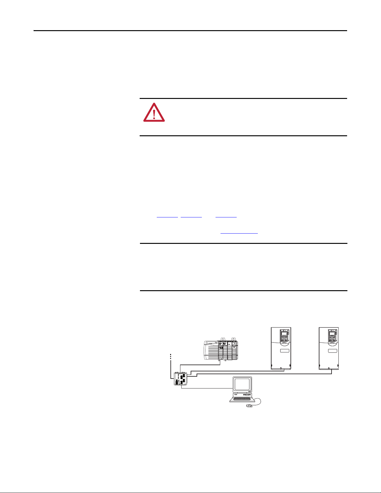
Control ler
(ControlLogix controller
shown with 1756-ENBT Bridge)
PowerFlex 750-Series Drives
(1)
(with 20-750-ENETR Option Modules)
External
Ethernet
Switch
Computer with
Ethernet Connection
To o ther
EtherNet/IP
networks
(1)
The ethernet cable may be connected to the option
module’s ENET1 or ENET 2 network port.
Connecting the Option Module to the Network
The option module is connected to the network differently depending on the
mode in which the option module is operated.
When Operating in Adapter Mode
ATTENTION: Risk of injury or death exists. The PowerFlex drive may contain high
voltages that can cause injury or death. Remove power from the drive, and then
verify power has been discharged before connecting the option module to the
network.
1. Remove power from the drive.
2. Remove the drive cover and lift up the drive HIM bezel to its open
position to access the drive control pod.
3. Use static control precautions.
4. Connect one end of the Ethernet cable to the network.
Examples of different EtherNet/IP network topologies are shown in
Figure 3
level ring (DLR) topologies, see EtherNet/IP Embedded Switch
Technology, publication ENET-AP005
, Figure 4, and Figure 5. For information about linear and device-
.
The option module has EtherNet/IP embedded switch technology, and ENET1
and ENET2 network ports to connect to a linear or device-level ring (DLR)
network in a single subnet.
You cannot use ENET1 and ENET 2 network ports as two network interface
cards connected to two different subnets.
Figure 3 - Connecting the Ethernet Cable in a Star Topology Network
Rockwell Automation Publication 750COM-UM008A-EN-P - July 2012 23
Chapter 2 Installing the Option Module
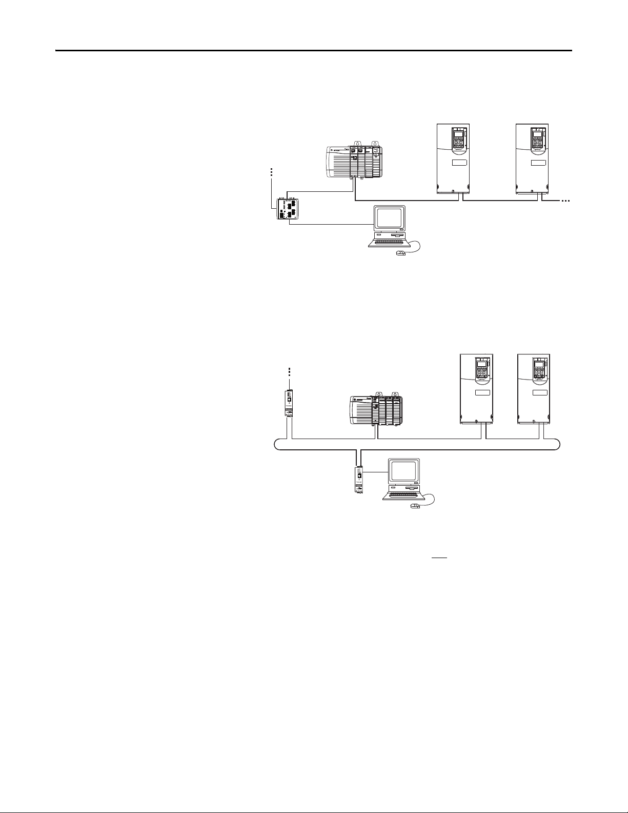
Controller
(ControlLogix controller
shown with 1756-ENBT Bridge)
PowerFlex 750-Series Drives
(1)
(with 20-750-ENETR Option Modules)
Ethernet
Switch
Computer with
Ethernet Connection
To o ther
EtherNet/IP
networks
(1)
The option module’s ENET1 and
ENET2 network ports are used.
Control ler
(ControlLogix controlle r
shown with 1756-ENBT Bridge)
PowerFlex 750-Series Drives
(1)
(with 20-750-ENETR Option Modules)
Computer with
Ethernet Connection
To o th er
EtherNet/IP
networks
1783-ETAP
1783-ETAP
(1)
The option module’s ENET1 and
ENET2 network ports are used.
Figure 4 - Connecting the Ethernet Cable in a Linear Topology Network
Figure 5 - Connecting the Ethernet Cable in a DLR Topology Network
5. Depending on the network topology, do one of the following:
• Star Network Topology—Route the other end of the Ethernet cable
from the network through the bottom of the drive, and insert its cable
plug into the option module’s ENET1 or ENET2 network port.
• Linear or DLR Network Topology—Route the other end of the
Ethernet cable from the network through the bottom of the first drive,
and insert its cable plug into the option module ENET1 network port.
To connect to the second drive, attach another Ethernet cable between
the first drive’s option module ENET2 network port and the second
drive’s option module ENET1 network port.
To connect additional drives, repeat these daisy-chain connections in
the same way.
24 Rockwell Automation Publication 750COM-UM008A-EN-P - July 2012
Installing the Option Module Chapter 2
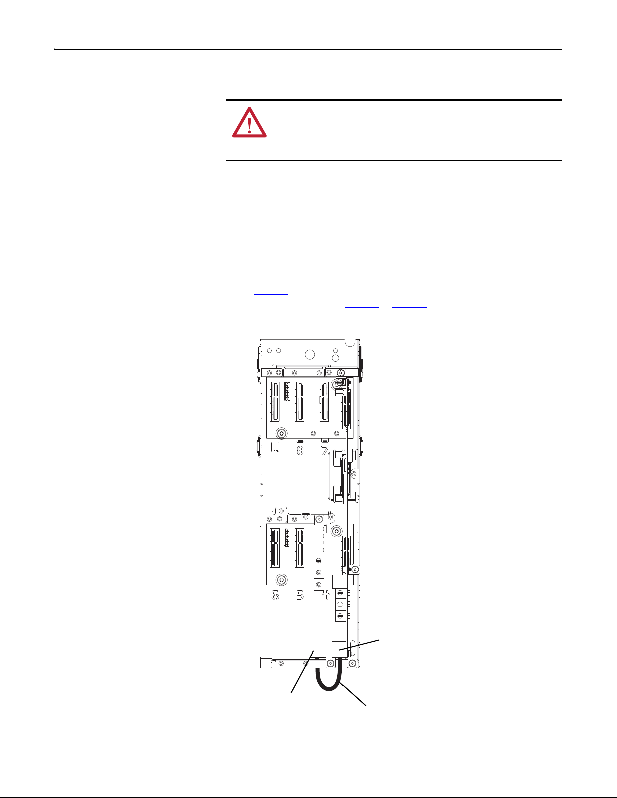
PowerFlex 755 Drive Control Pod
(drive shown with cover removed)
Ethernet Port on
PowerFlex 755 Drive
Embedded EtherNet/IP
Adapter
Option Module’s
ENET3 (DEVICE) Port
(bottom port
from top of card)
Short Ethernet Cable
(provided with option module; spare part
catalog number 1585J-M8CBJM-0M3)
When Operating in Tap Mode (only PowerFlex 755 drives)
ATTENTION: Risk of injury or death exists. The PowerFlex drive may contain high
voltages that can cause injury or death. Remove power from the drive, and then
verify power has been discharged before connecting the option module to the
network.
1. Remove power from the drive.
2. Remove the drive cover and lift up the drive HIM bezel to its open
position to access the drive control pod.
3. Use static control precautions.
4. Connect the short Ethernet cable (provided with the option module)
between the option module’s ENET3 (DEVICE) port and the Ethernet
port on the PowerFlex 755 drive’s embedded EtherNet/IP adapter (see
Figure 6
topology as shown in Figure 4
Figure 6 - Connecting the Short Ethernet Cable for Tap Mode of Operation
). (ENET1 and ENET2 ports are used for linear or DLR network
or Figure 5.)
5
6
4
7
3
8
2
9
1
0
5
6
4
7
3
8
2
9
1
0
5
6
4
7
3
8
2
9
1
0
Rockwell Automation Publication 750COM-UM008A-EN-P - July 2012 25

Chapter 2 Installing the Option Module
➊
➋
➌
➎
0
5
4
9
3
8
2
7
1
6
0
5
4
9
3
8
2
7
1
6
0
5
4
9
3
8
2
7
1
6
➍
For possible start-up status
indications, see Tabl e 1
for
Adapter mode operation or
Tab le 2 for Tap mode operation.
Drive Control Pod
(drive shown with cover removed)
Applying Power
ATTENTION: Risk of equipment damage, injury, or death exists. Unpredictable
operation may occur if you fail to verify that parameter settings are compatible
with your application. Verify that settings are compatible with your application
before applying power to the drive.
Apply power to the drive. The option module receives its power from the drive.
When you apply power to the option module for the first time, its topmost status
indicator (‘PORT’ for Adapter mode or ‘OK’ for Tap mode) should be steady
green or flashing green after an initialization. If it is red, there is a problem. See
Chapter 7
, Troubleshooting.
Start-Up Status Indications
After power has been applied, the drive STS (status) indicator can be viewed on
the front of the drive and the option module status indicators can be viewed with
the drive cover open or removed (Figure 7
Adapter mode than Tap mode. Depending on the operating mode, possible startup status indications are shown in Ta b l e 1
Figure 7 - Drive and Option Module Status Indicators
). The indicators operate differently in
or Ta b l e 2 respectively.
26 Rockwell Automation Publication 750COM-UM008A-EN-P - July 2012

Installing the Option Module Chapter 2
Table 1 - Adapter Mode – Drive and Option Module Start-Up Status Indications
Item Name Color State Description
Drive STS Indicator
STS
➊
(Status)
PORT Green Flashing Normal operation. The option module is establishing an I/O
➋
MOD Green Flashing Normal operation. The option module is operating but is not
➌
NET A Unlit Off Normal operation. DHCP is enabled or a valid IP address is not set.
➍
NET B Unlit Off Normal operation. The option module is properly connected, but is
➎
Green Flashing Drive ready but not running, and no faults are present.
Steady Drive running, no faults are present.
Yellow Flashing When running, a type 2 (non-configurable) alarm condition exists –
Steady A type 1 (user configurable) alarm condition exists, but the drive
Red Flashing A major fault has occurred. Drive will stop. Drive cannot be star ted
Steady A non-resettable fault has occurred.
Red/
Yellow
Yellow/
Green
Green/Red Flashing
Green Flashing Normal operation. DHCP is disabled, the option module is properly
Green Flashing Normal operation. The option module is properly connected, DHCP is
Flashing
Alternately
Flashing
Alternately
Alternately
Option Module Status Indicators—Adapter Mode
Steady Normal operation. The option module is properly connected and
Steady Normal operation. The option module is operating and transferring
Steady Normal operation. The option module is properly connected and
drive continues to run. When stopped, a start inhibit condition exists
and the drive cannot be started (see drive parameter 933 - [Start
Inhibits]).
continues to run.
until fault condition is cleared.
A minor fault has occurred. Use drive parameter 950 - [Minor Flt
Config] to enable. If not enabled, acts like a major fault. When
running, the drive continues to run. System is brought to a stop under
system control. The fault must be cleared to continue.
When running, a type 1 alarm exists.
Drive is updating.
connection to the drive. It will turn steady green or red.
communicating with the drive.
transferring I/O data to a controller.
I/O data to a controller.
connected, has an IP address, and is connected to an EtherNet/IP
network—but does not have an I/O connection.
communicating on the network to a controller.
idle.
enabled, and the option module is transmitting on the network.
After verifying correct operation, swing down the drive HIM bezel to its closed
position and install the drive cover. For more details on status indicator
operation, see page 114
Rockwell Automation Publication 750COM-UM008A-EN-P - July 2012 27
and page 115.

Chapter 2 Installing the Option Module
Table 2 - Tap Mode – PowerFlex 755 Drive and Option Module Start-Up Status Indications
Item Name Color State Description
Drive STS Indicator
STS
➊
(Status)
OK Green Flashing Normal operation. The option module is establishing DPI
➋
LINK 1
➌
LINK 2
➍
LINK 3
➎
Green Flashing Drive ready but not running, and no faults are present.
Steady Drive running, no faults are present.
Yellow Flashing When running, a type 2 (non-configurable) alarm condition exists –
Steady A type 1 (user configurable) alarm condition exists, but the drive
Red Flashing A major fault has occurred. Drive will stop. Drive cannot be star ted
Steady A non-resettable fault has occurred.
Red/
Yellow
Yellow/
Green
Green/Red Flashing
Unlit Off The option module is not properly connected to the network.
Green Flashing Normal operation. There is a 100 Mbps network link, with activity.
Yellow Flashing Normal operation. There is a 10 Mbps network link, with activity.
Flashing
Alternately
Flashing
Alternately
Alternately
Option Module Status Indicators—Tap Mode
Steady Normal operation. The option module has established DPI
Steady Normal operation. There is a 100 Mbps network link, no activity.
Steady Normal operation. There is a 10 Mbps network link, no activity.
drive continues to run. When stopped, a start inhibit condition exists
and the drive cannot be started (see drive parameter 933 - [Start
Inhibits]).
continues to run.
until fault condition is cleared.
A minor fault has occurred. Use drive parameter 950 - [Minor Flt
Config] to enable. If not enabled, acts like a major fault. When
running, the drive continues to run. System is brought to a stop under
system control. The fault must be cleared to continue.
When running, a type 1 alarm exists.
Drive is updating.
communication with the drive. It will turn steady green or red.
communication with the drive.
After verifying correct operation, swing down the drive HIM bezel to its closed
position and install the drive cover. For more details on status indicator
operation, see page 114
or page 116.
28 Rockwell Automation Publication 750COM-UM008A-EN-P - July 2012
Installing the Option Module Chapter 2
Configuring and Verifying Key Drive Parameters
The PowerFlex 750-Series drive can be separately configured for the control and
Reference functions in various combinations. For example, you could set the
drive to have its control come from a peripheral or terminal block with the
Reference coming from the network. Or you could set the drive to have its
control come from the network with the Reference coming from another
peripheral or terminal block. Or you could set the drive to have both its control
and Reference come from the network.
The following steps in this section assume that the drive will receive the Logic
Command and Reference from the network.
1. Verify that drive Parameter 301 - [Access Level] is set to “1” (Advanced) or
“2” (Expert) to access the required parameters in this procedure.
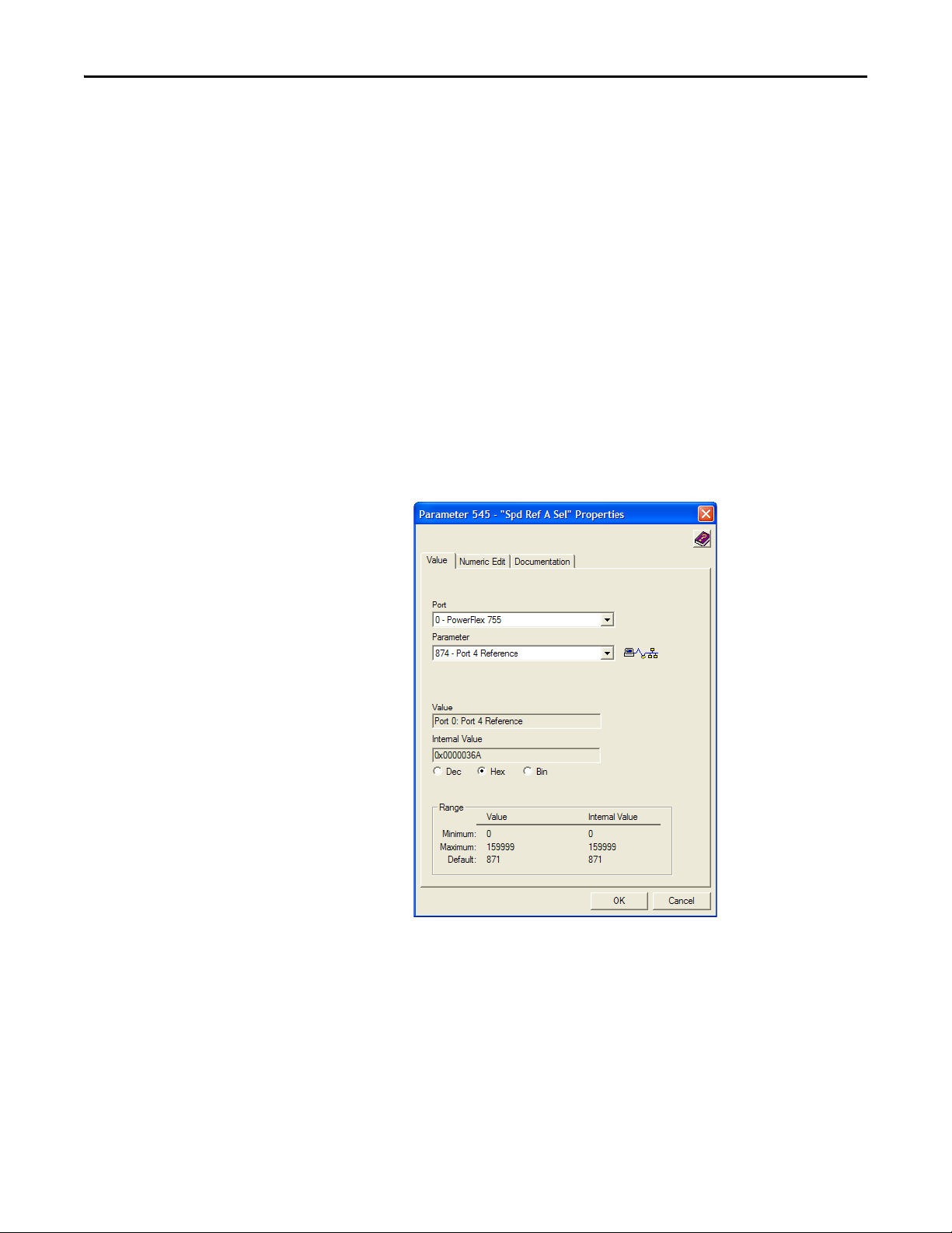
2. Use drive Parameter 545 - [Speed Ref A Sel] to set the drive speed
Reference:
a. Set the Port field to “0” as shown below.
b. Set the Parameter field to point to the port (slot) in which the option
module is installed (for this example, Port 4 Reference).
The number “874” in the Parameter field of the example dialog box
above is the parameter in the drive that points to the port.
3. Verify that drive Parameter 930 - [Speed Ref Source] is reporting that the
source of the Reference to the drive (Port 0) is the port in which the option
module is installed (for this example, Port 4 Reference).
This ensures that any Reference commanded from the network can be
monitored by using drive Parameter 002 - [Commanded SpdRef]. If a
Rockwell Automation Publication 750COM-UM008A-EN-P - July 2012 29

Chapter 2 Installing the Option Module
IMPORTANT
problem occurs, this verification step provides the diagnostic capability to
determine whether the drive/option module or the network is the cause.
4. If hard-wired discrete digital inputs are not used to control the drive, verify
that all unused digital input drive parameters are set to “0” (Not Used).
Commissioning the Option Module
To commission the option module, you must set a unique network node address.
See the Glossary
switches, see Setting the Node Address
these switches, a BOOTP or DHCP server or option module parameters can be
used to set the node address after connecting the option module to the network
and applying power to the drive.
By default, the option module is configured so that you must set the node address
using a DHCP server. For details, see Using a BOOTP or DHCP Server on
page 32. To set the node address using option module parameters, see Usi ng
Option Module Parameters on page 36.
for details about IP addresses. When using the Node Address
on page 20 for details. When not using
New settings for some option module parameters (for example, Device
Parameters 07 - [IP Addr Cfg 1] through 10 - [IP Addr Cfg 4]) are
recognized only when power is applied to the option module or it is reset. After
you change parameter settings, cycle power or reset the option module.
30 Rockwell Automation Publication 750COM-UM008A-EN-P - July 2012
Loading...