


 Loading...
User Manual
PanelView Plus 6 HMI Terminals
400, 600, 700, 1000, 1250, 1500
Important User Information
Solid-state equipment has operational characteristics differing from those of electromechanical equipment. Safety Guidelines for the Application, Installation and Maintenance of Solid State Controls (publication SGI-1.1 available from your local Rockwell Automation sales office or online at http://www.rockwellautomation.com/literature/) describes some important differences between solid-state equipment and hard-wired electromechanical devices. Because of this difference, and also because of the wide variety of uses for solid-state equipment, all persons responsible for applying this equipment must satisfy themselves that each intended application of this equipment is acceptable.
In no event will Rockwell Automation, Inc. be responsible or liable for indirect or consequential damages resulting from the use or application of this equipment.
The examples and diagrams in this manual are included solely for illustrative purposes. Because of the many variables and requirements associated with any particular installation, Rockwell Automation, Inc. cannot assume responsibility or liability for actual use based on the examples and diagrams.
No patent liability is assumed by Rockwell Automation, Inc. with respect to use of information, circuits, equipment, or software described in this manual.
Reproduction of the contents of this manual, in whole or in part, without written permission of Rockwell Automation, Inc., is prohibited.
Throughout this manual, when necessary, we use notes to make you aware of safety considerations.
WARNING: Identifies information about practices or circumstances that can cause an explosion in a hazardous environment, which may lead to personal injury or death, property damage, or economic loss.
ATTENTION: Identifies information about practices or circumstances that can lead to personal injury or death, property damage, or economic loss. Attentions help you identify a hazard, avoid a hazard, and recognize the consequence.
SHOCK HAZARD: Labels may be on or inside the equipment, for example, a drive or motor, to alert people that dangerous voltage may be present.
BURN HAZARD: Labels may be on or inside the equipment, for example, a drive or motor, to alert people that surfaces may reach dangerous temperatures.
IMPORTANT Identifies information that is critical for successful application and understanding of the product.
Allen-Bradley, Rockwell Software, Rockwell Automation, PanelView, FactoryTalk, RSLinx, CompactLogix, ControlLogix, SLC, MicroLogix, PLC-5, RSView, and TechConnect are trademarks of Rockwell Automation, Inc.
Trademarks not belonging to Rockwell Automation are property of their respective companies.

Summary of Changes
New and Updated
Information
This manual contains new and updated information. Changes throughout this revision are marked by change bars, as shown to the right of this paragraph.
This table contains the changes made to this revision. Most of the updates are the result of adding the new generation PanelView™ Plus 6 - 400 and 600 terminals to the publication.
Topic |
Page |
|
|
Updated operating system features table |
12 |
|
|
Added terminal features for 400 and 600 terminals |
14 |
|
|
Add new catalog numbers for 400 and 600 terminals |
20 |
|
|
Added reference to new Ethernet communication module for |
17, 23, 60, 62, 140 |
700 to 1500 terminals |
|
|
|
Updated accessories to include those for 400 and 600 terminals |
22 |
|
|
Updated temperature codes to include those for the 400 and 600 terminals |
28 |
|
|
Added panel cutout dimensions for 400 and 600 terminals |
30 |
|
|
Added product dimensions for the 400 and 600 terminals |
31 |
|
|
Added installation procedure for 400 and 600 terminals |
33 |
|
|
Added procedure for removing terminal block |
37 |
|
|
Updated power connections for 400 and 600 terminals |
38…42 |
|
|
Updated Server Support table for the 400 and 600 terminals |
87 |
|
|
Updated Windows Control Panel table |
89 |
|
|
Added battery replacement procedure for 400 and 600 terminals |
130 |
|
|
Added procedure to install AC power supply module for 400 and 600 terminals |
132 |
|
|
Updated the USB Ports section to include the 400 and 600 terminals |
138 |
|
|
Updated the Ethernet Connections section to include the 400 and 600 terminals |
140 |
|
|
Updated tables in the Connections to Controllers section |
151 |
|
|
Updated the Firmware Upgrade chapter to include the 400 and 600 terminals |
153 |
|
|
Moved information on outdoor installation for high-bright module display |
177 |
|
|
Rockwell Automation Publication 2711P-UM006C-EN-P - April 2013 |
3 |

Summary of Changes
Notes:
4 |
Rockwell Automation Publication 2711P-UM006C-EN-P - April 2013 |

|
|
Table of Contents |
|
Important User Information . . . . . . . . . . . . . . . . . . . . . . . . |
. . . . . . . . . . . . . . . . 2 |
Summary of Changes |
New and Updated Information . . . . . . . . . . . . . . . . . . . . . . |
. . . . . . . . . . . . . . . 3 |
Preface |
Additional Resources . . . . . . . . . . . . . . . . . . . . . . . . . . . . . . . . |
. . . . . . . . . . . . . . . 9 |
|
Package Contents . . . . . . . . . . . . . . . . . . . . . . . . . . . . . . . . . . . |
. . . . . . . . . . . . . . . 9 |
|
Firmware Upgrades . . . . . . . . . . . . . . . . . . . . . . . . . . . . . . . . . |
. . . . . . . . . . . . . . . 9 |
|
Chapter 1 |
|
Overview |
About the Terminals . . . . . . . . . . . . . . . . . . . . . . . . . . . . . . . . |
. . . . . . . . . . . . . 11 |
|
Windows CE Operating System. . . . . . . . . . . . . . . . . . . . . . |
. . . . . . . . . . . . . 12 |
|
Open versus Closed System . . . . . . . . . . . . . . . . . . . . . . . . . . |
. . . . . . . . . . . . . 12 |
|
Start-up Options . . . . . . . . . . . . . . . . . . . . . . . . . . . . . . . . . . . . |
. . . . . . . . . . . . . 13 |
|
Desktop Access . . . . . . . . . . . . . . . . . . . . . . . . . . . . . . . . . . . . . |
. . . . . . . . . . . . . 13 |
|
Software Support . . . . . . . . . . . . . . . . . . . . . . . . . . . . . . . . . . . |
. . . . . . . . . . . . . 13 |
|
400 and 600 Terminal Features . . . . . . . . . . . . . . . . . . . . . . |
. . . . . . . . . . . . . 14 |
|
700 to 1500 Terminal Features . . . . . . . . . . . . . . . . . . . . . . . |
. . . . . . . . . . . . . 17 |
|
400/600 Terminal Selections . . . . . . . . . . . . . . . . . . . . . . . . |
. . . . . . . . . . . . . 20 |
|
700 to 1500 Terminal Selections . . . . . . . . . . . . . . . . . . . . . |
. . . . . . . . . . . . . 21 |
|
Accessories . . . . . . . . . . . . . . . . . . . . . . . . . . . . . . . . . . . . . . . . . |
. . . . . . . . . . . . . 22 |
|
Chapter 2 |
|
Install Terminal |
Mounting Clearances. . . . . . . . . . . . . . . . . . . . . . . . . . . . . . . . |
. . . . . . . . . . . . . 30 |
|
Panel Guidelines . . . . . . . . . . . . . . . . . . . . . . . . . . . . . . . . . . . . |
. . . . . . . . . . . . . 30 |
|
Panel Cutout Dimensions . . . . . . . . . . . . . . . . . . . . . . . . . . . |
. . . . . . . . . . . . . 30 |
|
Product Dimensions . . . . . . . . . . . . . . . . . . . . . . . . . . . . . . . . |
. . . . . . . . . . . . . 31 |
|
Mount the 400/600 Terminal in a Panel . . . . . . . . . . . . . . |
. . . . . . . . . . . . . 33 |
|
Mount the 700 to 1500 Terminal in a Panel . . . . . . . . . . . |
. . . . . . . . . . . . . 35 |
|
Remove and Install the Power Terminal Block. . . . . . . . . |
. . . . . . . . . . . . . 37 |
|
DC Power Connections . . . . . . . . . . . . . . . . . . . . . . . . . . . . . |
. . . . . . . . . . . . . 38 |
|
AC Power Connections . . . . . . . . . . . . . . . . . . . . . . . . . . . . . |
. . . . . . . . . . . . . 41 |
|
Initial Startup. . . . . . . . . . . . . . . . . . . . . . . . . . . . . . . . . . . . . . . |
. . . . . . . . . . . . . 43 |
|
Reset the Terminal . . . . . . . . . . . . . . . . . . . . . . . . . . . . . . . . . . |
. . . . . . . . . . . . . 43 |
|
Chapter 3 |
|
Configuration Mode |
Access Configuration Mode. . . . . . . . . . . . . . . . . . . . . . . . . . |
. . . . . . . . . . . . . 45 |
|
Terminal Settings . . . . . . . . . . . . . . . . . . . . . . . . . . . . . . . . . . . |
. . . . . . . . . . . . . 48 |
|
Load and Run Application . . . . . . . . . . . . . . . . . . . . . . . . . . . |
. . . . . . . . . . . . . 50 |
|
Start-up Options . . . . . . . . . . . . . . . . . . . . . . . . . . . . . . . . . . . . |
. . . . . . . . . . . . . 51 |
|
Desktop Access . . . . . . . . . . . . . . . . . . . . . . . . . . . . . . . . . . . . . |
. . . . . . . . . . . . . 54 |
|
Communication Setup . . . . . . . . . . . . . . . . . . . . . . . . . . . . . . |
. . . . . . . . . . . . . 58 |
|
Ethernet Network Connections . . . . . . . . . . . . . . . . . . . . . . |
. . . . . . . . . . . . . 60 |
|
File Management. . . . . . . . . . . . . . . . . . . . . . . . . . . . . . . . . . . . |
. . . . . . . . . . . . . 64 |
|
Display Settings . . . . . . . . . . . . . . . . . . . . . . . . . . . . . . . . . . . . . |
. . . . . . . . . . . . . 67 |
|
Input Device Settings. . . . . . . . . . . . . . . . . . . . . . . . . . . . . . . . |
. . . . . . . . . . . . . 69 |
Rockwell Automation Publication 2711P-UM006C-EN-P - April 2013 |
5 |

Table of Contents |
|
|
|
Configure Print Options . . . . . . . . . . . . . . . . . . . . . . . . . . . . . . . . . . . . . . . . . |
. 72 |
|
Check Integrity of Application Files . . . . . . . . . . . . . . . . . . . . . . . . . . . . . . . |
74 |
|
Configure Diagnostics . . . . . . . . . . . . . . . . . . . . . . . . . . . . . . . . . . . . . . . . . . . . |
75 |
|
View and Clear the System Event Log . . . . . . . . . . . . . . . . . . . . . . . . . . . . . . |
76 |
|
System Information . . . . . . . . . . . . . . . . . . . . . . . . . . . . . . . . . . . . . . . . . . . . . . |
76 |
|
Enable or Disable the Alarm Display . . . . . . . . . . . . . . . . . . . . . . . . . . . . . . . |
78 |
|
Time and Date Settings . . . . . . . . . . . . . . . . . . . . . . . . . . . . . . . . . . . . . . . . . . . |
79 |
|
Regional Settings . . . . . . . . . . . . . . . . . . . . . . . . . . . . . . . . . . . . . . . . . . . . . . . . . |
81 |
|
Font Linking. . . . . . . . . . . . . . . . . . . . . . . . . . . . . . . . . . . . . . . . . . . . . . . . . . . . . |
84 |
|
Chapter 4 |
|
Windows CE Operating System |
Windows CE 6.0 Standard Features. . . . . . . . . . . . . . . . . . . . . . . . . . . . . . . . |
85 |
|
Windows CE 6.0 with Extended Features . . . . . . . . . . . . . . . . . . . . . . . . . . |
87 |
|
Windows Explorer . . . . . . . . . . . . . . . . . . . . . . . . . . . . . . . . . . . . . . . . . . . . . . . |
88 |
|
Taskbar. . . . . . . . . . . . . . . . . . . . . . . . . . . . . . . . . . . . . . . . . . . . . . . . . . . . . . . . . . |
88 |
|
Input Panels . . . . . . . . . . . . . . . . . . . . . . . . . . . . . . . . . . . . . . . . . . . . . . . . . . . . . |
88 |
|
Windows Control Panel . . . . . . . . . . . . . . . . . . . . . . . . . . . . . . . . . . . . . . . . . . |
89 |
|
Backup and Restore. . . . . . . . . . . . . . . . . . . . . . . . . . . . . . . . . . . . . . . . . . . . . . . |
90 |
|
Hardware Monitor . . . . . . . . . . . . . . . . . . . . . . . . . . . . . . . . . . . . . . . . . . . . . . . |
93 |
|
Keypad Properties . . . . . . . . . . . . . . . . . . . . . . . . . . . . . . . . . . . . . . . . . . . . . . . . |
95 |
|
Touch Properties . . . . . . . . . . . . . . . . . . . . . . . . . . . . . . . . . . . . . . . . . . . . . . . . . |
95 |
|
Display Properties . . . . . . . . . . . . . . . . . . . . . . . . . . . . . . . . . . . . . . . . . . . . . . . . |
96 |
|
Logo Manager. . . . . . . . . . . . . . . . . . . . . . . . . . . . . . . . . . . . . . . . . . . . . . . . . . . . |
98 |
|
System Information . . . . . . . . . . . . . . . . . . . . . . . . . . . . . . . . . . . . . . . . . . . . . . |
99 |
|
User Accounts . . . . . . . . . . . . . . . . . . . . . . . . . . . . . . . . . . . . . . . . . . . . . . . . . . |
102 |
|
Services . . . . . . . . . . . . . . . . . . . . . . . . . . . . . . . . . . . . . . . . . . . . . . . . . . . . . . . . . |
103 |
|
Network Server Configuration . . . . . . . . . . . . . . . . . . . . . . . . . . . . . . . . . . . |
104 |
|
Printer Support . . . . . . . . . . . . . . . . . . . . . . . . . . . . . . . . . . . . . . . . . . . . . . . . . |
113 |
|
PDF Reader. . . . . . . . . . . . . . . . . . . . . . . . . . . . . . . . . . . . . . . . . . . . . . . . . . . . . |
116 |
|
Image Viewer . . . . . . . . . . . . . . . . . . . . . . . . . . . . . . . . . . . . . . . . . . . . . . . . . . . |
117 |
|
Chapter 5 |
|
Install and Replace Components |
Required Tools. . . . . . . . . . . . . . . . . . . . . . . . . . . . . . . . . . . . . . . . . . . . . . . . . . |
119 |
|
Install or Replace the Logic Module . . . . . . . . . . . . . . . . . . . . . . . . . . . . . . . |
120 |
|
Install or Replace a Communication Module . . . . . . . . . . . . . . . . . . . . . . |
121 |
|
Replace the Display Module . . . . . . . . . . . . . . . . . . . . . . . . . . . . . . . . . . . . . . |
123 |
|
Replace the Bezel . . . . . . . . . . . . . . . . . . . . . . . . . . . . . . . . . . . . . . . . . . . . . . . . |
124 |
|
Replace the Backlight . . . . . . . . . . . . . . . . . . . . . . . . . . . . . . . . . . . . . . . . . . . . |
126 |
|
Replace the Battery . . . . . . . . . . . . . . . . . . . . . . . . . . . . . . . . . . . . . . . . . . . . . . |
130 |
|
Install the AC Power Supply Module . . . . . . . . . . . . . . . . . . . . . . . . . . . . . |
132 |
|
Remove the Product ID Label . . . . . . . . . . . . . . . . . . . . . . . . . . . . . . . . . . . . |
134 |
|
Replace the Keypad Legend Inserts. . . . . . . . . . . . . . . . . . . . . . . . . . . . . . . . |
134 |
|
Load an SD Card . . . . . . . . . . . . . . . . . . . . . . . . . . . . . . . . . . . . . . . . . . . . . . . . |
135 |
|
Clean the Display . . . . . . . . . . . . . . . . . . . . . . . . . . . . . . . . . . . . . . . . . . . . . . . |
136 |
6 |
Rockwell Automation Publication 2711P-UM006C-EN-P - April 2013 |

|
|
Table of Contents |
|
Chapter 6 |
|
Terminal Connections |
USB Ports . . . . . . . . . . . . . . . . . . . . . . . . . . . . . . . . . . . . . . . . . . . . . . . |
. . . . . . . 138 |
|
Ethernet Connections . . . . . . . . . . . . . . . . . . . . . . . . . . . . . . . . . . . . . |
. . . . . . 140 |
|
Serial Connections . . . . . . . . . . . . . . . . . . . . . . . . . . . . . . . . . . . . . . . . |
. . . . . . 142 |
|
DH-485/DH+ Communication Module . . . . . . . . . . . . . . . . . . . |
. . . . . . 145 |
|
ControlNet Communication Module . . . . . . . . . . . . . . . . . . . . . . |
. . . . . . 148 |
|
Controller Connections . . . . . . . . . . . . . . . . . . . . . . . . . . . . . . . . . . . |
. . . . . . 151 |
|
Chapter 7 |
|
Firmware Upgrades |
Terminal Firmware . . . . . . . . . . . . . . . . . . . . . . . . . . . . . . . . . . . . . . . |
. . . . . . 153 |
|
Download Firmware Files. . . . . . . . . . . . . . . . . . . . . . . . . . . . . . . . . . |
. . . . . . 154 |
|
Firmware Upgrade Wizard. . . . . . . . . . . . . . . . . . . . . . . . . . . . . . . . . |
. . . . . . 154 |
|
Upgrading Terminal Firmware from a Storage Device . . . . . . . . |
. . . . . . 155 |
|
Upgrade Terminal Firmware over the Network. . . . . . . . . . . . . . |
. . . . . . 158 |
|
Chapter 8 |
|
Troubleshooting |
Status Indicators . . . . . . . . . . . . . . . . . . . . . . . . . . . . . . . . . . . . . . . . . . |
. . . . . . 161 |
|
Terminal Does Not Start Properly. . . . . . . . . . . . . . . . . . . . . . . . . . |
. . . . . . 162 |
|
Start-up Messages and Codes. . . . . . . . . . . . . . . . . . . . . . . . . . . . . . . |
. . . . . . 164 |
|
Check Terminal Components . . . . . . . . . . . . . . . . . . . . . . . . . . . . . |
. . . . . . 166 |
|
Ethernet Connection. . . . . . . . . . . . . . . . . . . . . . . . . . . . . . . . . . . . . . |
. . . . . . 167 |
|
Program Launcher ActiveX Control . . . . . . . . . . . . . . . . . . . . . . . . |
. . . . . . 168 |
|
Application Does Not Run . . . . . . . . . . . . . . . . . . . . . . . . . . . . . . . . |
. . . . . . 168 |
|
Configuration Mode Access. . . . . . . . . . . . . . . . . . . . . . . . . . . . . . . . |
. . . . . . 168 |
|
File System Errors . . . . . . . . . . . . . . . . . . . . . . . . . . . . . . . . . . . . . . . . . |
. . . . . . 169 |
|
Advanced Diagnostics . . . . . . . . . . . . . . . . . . . . . . . . . . . . . . . . . . . . . |
. . . . . . 169 |
|
Access Maintenance Operations. . . . . . . . . . . . . . . . . . . . . . . . . . . . |
. . . . . . 170 |
|
Restore Factory Defaults. . . . . . . . . . . . . . . . . . . . . . . . . . . . . . . . . . . |
. . . . . . 172 |
|
Appendix A |
|
Fonts Resident on Terminal |
True Type Fonts . . . . . . . . . . . . . . . . . . . . . . . . . . . . . . . . . . . . . . . . . . |
. . . . . . 175 |
|
Appendix B |
|
Outdoor Installations for High-bright |
Important Considerations . . . . . . . . . . . . . . . . . . . . . . . . . . . . . . . . . |
. . . . . . 177 |
Displays |
Using an Antiglare Overlay . . . . . . . . . . . . . . . . . . . . . . . . . . . . . . . . |
. . . . . . 177 |
|
Using a Solar Visor . . . . . . . . . . . . . . . . . . . . . . . . . . . . . . . . . . . . . . . . |
. . . . . . 177 |
|
Selecting an Enclosure . . . . . . . . . . . . . . . . . . . . . . . . . . . . . . . . . . . . . |
. . . . . . 178 |
|
Backlight Considerations . . . . . . . . . . . . . . . . . . . . . . . . . . . . . . . . . . |
. . . . . . 178 |
|
Orientation of the Terminal . . . . . . . . . . . . . . . . . . . . . . . . . . . . . . . |
. . . . . . 178 |
Index |
. . . . . . . . . . . . . . . . . . . . . . . . . . . . . . . . . . . . . . . . . . . . . . . . . . . . . . . . . . |
. . . . . . 179 |
Rockwell Automation Publication 2711P-UM006C-EN-P - April 2013 |
7 |

Table of Contents
Notes:
8 |
Rockwell Automation Publication 2711P-UM006C-EN-P - April 2013 |

Preface
Additional Resources
Package Contents
Firmware Upgrades
This manual describes how to install, configure, operate, and troubleshoot PanelView Plus 6 terminals. It does not provide procedures on how to create applications that run on the terminal.
You also need to do the following:
•Use FactoryTalk® View Studio for Machine Edition software to create an HMI application to run in the terminal.
•Create ladder logic to interact with the HMI application.
These documents contain additional information concerning related products from Rockwell Automation.
Resource |
Description |
|
|
PanelView Plus Specifications Technical Data, publication |
Provides technical specifications, environmental |
2711P-TD005 |
specifications, and certifications for the PanelView Plus 6 |
|
platform. |
|
|
Industrial Automation Wiring and Grounding Guidelines, |
Provides general guidelines for installing a Rockwell |
publication 1770-4.1 |
Automation® industrial system. |
|
|
Product Certifications website, http://www.ab.com |
Provides declarations of conformity, certificates, and other |
|
certification details. |
|
|
You can view or download publications at http://www.rockwellautomation.com/literature/. To order paper copies of technical documentation, contact your local Allen-Bradley distributor or Rockwell Automation sales representative.
This product is shipped with the following items:
•Terminal with FactoryTalk View Machine Edition runtime software installed and activated
•Product information
•Mounting levers for installing 400 and 600 terminals
•Mounting clips for installing 700 to 1500 terminals
•Panel cutout template
For the latest firmware upgrades and other downloads for PanelView Plus 6 terminals, go to http://www.rockwellautomation.com/support and click Firmware Updates.
Rockwell Automation Publication 2711P-UM006C-EN-P - April 2013 |
9 |

Preface
Notes:
10 |
Rockwell Automation Publication 2711P-UM006C-EN-P - April 2013 |
Chapter 1
Overview
About the Terminals
Topic |
Page |
|
|
Windows CE Operating System |
12 |
|
|
Open versus Closed System |
12 |
|
|
Desktop Access |
13 |
|
|
Software Support |
13 |
|
|
400 and 600 Terminal Features |
14 |
|
|
700 to 1500 Terminal Features |
17 |
|
|
400/600 Terminal Selections |
20 |
|
|
700 to 1500 Terminal Selections |
21 |
|
|
Accessories |
22 |
|
|
PanelView Plus 6 terminals are operator interface devices that run HMI machine-level applications in an industrial environment. The displays range in size from 4 to 15-inches. These devices are used to monitor, control, or display information graphically, letting operators quickly understand the status of their application.
This platform is programmed by using common development software that provides multi-language support, and integrates into systems with Rockwell Automation controllers including preferred Logix controllers.
Rockwell Automation Publication 2711P-UM006C-EN-P - April 2013 |
11 |
Chapter 1 |
Overview |
|
|
Windows CE Operating
System
PanelView Plus 6 terminals run the Windows CE operating system (OS), providing the foundational OS elements for the majority of user needs.
For users with more complex application requirements, some of the terminals offer optional, extended features and file viewers.
Table 1 - Operating System Features
|
|
Features |
400 Terminals |
600 Terminals |
700 to 1500 Terminals |
|||||
|
|
|||||||||
|
|
|
|
|
|
|
|
|
|
|
|
|
|
Cat. Nos. |
2711P-xxxx8 |
2711P-xxxx8 |
2711P-xxxx9 |
2711P-xxxx8 |
2711P-xxxx9 |
||
|
|
|
2711P-RP8x |
2711P-RP9x |
||||||
|
|
|
|
|
|
|
|
|
||
|
|
|
|
|
|
|
|
|
|
|
|
|
Standard Features |
|
|
|
|
|
|||
|
|
|
|
|
|
|
||||
|
|
|
|
|
|
|
|
|
|
|
|
|
FTP server |
• |
• |
• |
• |
• |
|||
|
|
|
|
|
|
|
|
|
|
|
|
|
VNC client/server |
• |
• |
• |
• |
• |
|||
|
|
|||||||||
|
|
|
|
|
|
|
|
|
|
|
|
|
ActiveX controls(1) |
• |
• |
• |
• |
• |
|||
|
|
|||||||||
|
|
|
|
|
|
|
|
|
|
|
|
|
Third-party device support |
• |
• |
• |
• |
• |
|||
|
|
|||||||||
|
|
|
|
|
|
|
|
|
|
|
|
|
PDF reader |
• |
• |
• |
• |
• |
|||
|
|
|||||||||
|
|
|
|
|
|
|
|
|
|
|
|
|
Optional Extended Features |
|
|
|
|
|
|||
|
|
|
|
|
|
|
||||
|
|
|
|
|
|
|
|
|
|
|
|
|
Web browser - Internet Explorer |
— |
— |
• |
— |
• |
|||
|
|
|
|
|
|
|
|
|
|
|
|
|
Remote desktop connection |
— |
— |
• (2) |
— |
• |
|||
|
|
|||||||||
|
|
|
|
|
|
|
|
|
|
|
|
|
Media player |
— |
— |
• |
— |
• |
|||
|
|
|||||||||
|
|
|
|
|
|
|
|
|
|
|
|
|
Microsoft Office file viewers |
|
|
|
|
|
|||
|
|
|
|
|
|
|
||||
|
|
• |
PowerPoint |
— |
— |
• |
— |
• |
||
|
|
|
|
|
|
|
|
|
||
|
|
• |
Excel |
|
|
— |
— |
• |
— |
• |
|
|
|
|
|
|
|
|
|
||
|
|
• |
Word |
— |
— |
• |
— |
• |
||
|
|
|
|
|
||||||
|
|
|
|
|
|
|
|
|
|
|
|
|
|
|
|
|
|
|
|
|
|
|
|
WordPad text editor |
— |
— |
• |
— |
• |
|||
|
|
|||||||||
|
|
|
|
|
|
|
|
|
|
|
(1)Refer to Display FactoryTalk View ME Station Information on page 78 for a list of ActiveX controls loaded on a terminal.
(2)The remote desktop connection is not currently supported on PanelView Plus 6 - 600 terminals with extended features.
Open versus Closed System |
The terminals can be configured to run an open or closed desktop environment: |
|
• An open system launches the Windows Explorer desktop on startup. The |
|
system is configurable via the control panel and supports Windows |
|
operations. |
|
• A closed system launches a FactoryTalk View Machine Edition application |
|
on startup and restricts access to the Windows Explorer desktop. |
|
All terminals are shipped as closed systems restricting access to the desktop. The |
|
first time you start the system, the terminal launches FactoryTalk View ME |
|
Station Configuration mode. At this point, you can change the start-up option |
|
and allow desktop access. |
12 |
Rockwell Automation Publication 2711P-UM006C-EN-P - April 2013 |

Overview |
Chapter 1 |
|
|
Start-up Options
Desktop Access
You can configure the terminal to perform one of three actions at startup:
•Launch a FactoryTalk View Machine Edition HMI application.
•Launch the FactoryTalk View Machine Edition Configuration mode of the terminal where you load and run applications, configure start-up options and terminal settings, and enable or disable desktop access.
•Launch the Windows Explorer desktop.
The factory default state and start-up option following a firmware upgrade is to launch the terminal in Configuration mode. Refer to Start-up Options on page 51 for details on how to change the start-up option.
Any of the terminals can be configured to allow or restrict desktop access. From the desktop, you can perform system and control panel operations, or run third-party applications. Terminals with optional, extended features (catalog numbers ending in 9) can additionally run viewers, media players, and launch the web browser. You can even allow access temporarily to perform specific tasks, then disable desktop access to prevent unauthorized changes.
TIP |
All terminals are initially shipped with desktop access disabled. |
Refer to Desktop Access on page 54 for details on how to modify desktop access.
IMPORTANT Desktop access does not change the feature set of your terminal. If you have a terminal with a catalog number ending in 8, opening the desktop does not give you access to extended features and file viewers.
Software Support |
The table lists software supported on the terminals. |
|
|
|
Table 2 - PanelView Plus 6 Software Support |
|
|
||
|
|
|
|
|
|
Software |
Description |
Version |
|
|
|
|
|
|
|
FactoryTalk View Machine Edition Station |
Runtime environment for FactoryTalk View Machine Edition .mer applications. Machine Edition |
• |
6.10 or later |
|
|
Station is preloaded on each terminal and does not require FactoryTalk View activation. |
• |
(400 and 600 terminals) |
|
|
|
6.0 or later |
|
|
FactoryTalk View Studio for |
Configuration software for developing HMI applications that run on PanelView Plus 6 terminals. |
||
|
|
(700 to 1500 terminals) |
||
|
Machine Edition |
RSLinx® Enterprise software is included with FactoryTalk View Studio software and loaded during |
|
|
|
|
installation. |
|
|
|
|
|
|
|
|
FactoryTalk ViewPoint |
Add-on capability provided with FactoryTalk View Studio software: |
1.2 or later |
|
|
(700 to 1500 terminals only) |
• This web-based, thin-client solution lets manufacturers or casual users monitor or download |
|
|
|
|
changes to a running Machine Edition application from remote locations via an Internet |
|
|
|
|
browser. |
|
|
|
|
• A single license is embedded with each terminal supporting a single client connection to |
|
|
|
|
terminal. No additional software is required. |
|
|
|
|
|
|
|
|
Windows CE 6.0 OS |
Operating system that runs on all terminals. |
6.0 |
|
|
|
|
|
|
Rockwell Automation Publication 2711P-UM006C-EN-P - April 2013 |
13 |

Chapter 1 |
Overview |
|
|
400 and 600 Terminal
Features
Both the 400 and 600 terminals provide these communication options:
•RS-232 serial port only or
•Ethernet port and RS-232 serial port
Figure 1 - 400 Keypad or Keypad/Touch Terminals

 1
1
12
11 
10 |
|
2 |
3b |
9 |
|
|
|
|
|
|
|
8 |
|
3a |
|
|
|
4 |
|
7 |
6 |
5 |
|
Table 3 - PanelView Plus 6 - 400 Terminal Components
Item Component
13.5-in. grayscale or color display with one of these operator input options:
•Keypad
•Combination keypad and touch screen
2Secure Digital (SD) card slot supporting cat. no. 1784-SDx cards
3a |
DC power input, nonisolated(1) |
|
24V DC nom (18…30V DC) |
|
|
3b |
AC power supply module with AC power input (1) |
|
100…240V AC (50…60 Hz) |
|
|
4 |
Mounting slots (four) |
|
|
5 |
Ethernet port for controller communication, 10/100Base-T, Auto MDI/MDI-X (2) |
6 |
RS-232 serial port for controller communication, printing, or file transfers |
7One USB 2.0 high-speed (type A) host port for attaching USB peripherals including mouse, keyboard, printer, and USB drives that are hot-swappable in nonhazardous locations
8 |
One USB 2.0 high-speed (type B) device port for connecting a host computer |
9 |
Reset switch to reset the terminal without having to power off and on |
|
|
10 |
Default switch to access maintenance operations such as restoring factory defaults |
|
|
11 |
Battery compartment |
|
|
12 |
Indicators provide communication and fault status |
(1)Presence of a DC power input or AC power supply module is catalog number dependent. Removing the AC power supply module voids the terminal warranty.
(2)Presence of Ethernet port is catalog number dependent.
14 |
Rockwell Automation Publication 2711P-UM006C-EN-P - April 2013 |
Overview |
Chapter 1 |
|
|
|
Figure 2 - 600 Touch Terminals |
|
1a |
|
12 |
11 |
|
10 |
3b |
2 |
|
9 |
|
8 |
3a |
|
7 6 5 4
|
Figure 3 - 600 Keypad or Keypad/Touch Terminals |
||||
|
|
|
|
|
1b |
12 |
F1 |
F2 |
F3 |
F4 |
F5 |
|
F6 |
F7 |
F8 |
F9 |
F10 |
11 
10 |
|
|
2 |
3b |
9 |
|
|
|
|
8 |
|
|
3a |
|
|
|
|
|
|
7 |
6 |
5 |
4 |
|
Table 4 - PanelView Plus 6 - 600 Terminal Components
Item |
Component |
Item |
Component |
|
|
|
|
1a |
5.7-in. color or grayscale display with a touch screen |
6 |
RS-232 serial port for controller communication, printing, or file transfers |
|
|
|
|
1b |
5.7-in. color or grayscale display with either a: |
7 |
One USB 2.0 high-speed (type A) host port for attaching USB peripherals |
|
• Keypad |
|
including mouse, keyboard, printer, and USB drives that are hot-swappable in |
|
• Combination keypad and touch screen |
|
nonhazardous locations |
|
|
|
|
2 |
Secure Digital (SD) card slot supporting cat. no. 1784-SDx cards |
8 |
One USB 2.0 high-speed (type B) device port for connecting a host computer |
|
|
|
|
3a |
DC power input, nonisolated(1) |
9 |
Reset switch to reset the terminal without having to power off and on |
|
24V DC nom (18…30V DC) |
|
|
|
|
|
|
3b |
AC power supply module with AC power input(1) |
10 |
Default switch to access maintenance operations such as restoring factory |
|
100…240V AC (50…60 Hz) |
|
defaults |
|
|
|
|
4 |
Mounting slots (four on touch terminals; six on keypad terminals) |
11 |
Battery compartment |
|
|
|
|
5 |
Ethernet port for controller communication, 10/100Base-T, Auto MDI/MDI-X (2) |
12 |
Indicators provide communication and fault status |
(1)Presence of a DC power input or the AC power supply module is catalog number dependent. Removing the AC power supply module voids the terminal warranty.
(2)Presence of Ethernet port is catalog number dependent.
Rockwell Automation Publication 2711P-UM006C-EN-P - April 2013 |
15 |
Chapter 1 |
Overview |
|
|
The terminals feature grayscale or color LCD displays with these input options.
Table 5 - Operator Input Options
Terminal |
Display Type |
Keypad |
Touch |
Key and Touch |
|
|
|
|
|
400 |
Grayscale |
• |
|
|
|
|
|
|
|
|
Color |
• |
|
• |
|
|
|
|
|
600 |
Grayscale |
• |
• |
• |
|
|
|
|
|
|
Color |
• |
• |
• |
|
|
|
|
|
1 |
2 |
5 |
F1 |
F2 |
F3 |
F4 |
F5 |
F6 |
F7 |
F8 |
F9 |
F10 |
3
4
Table 6 - Display and Operator Input Features
Item |
Feature |
Description |
|
|
|
|
|
1 |
Product label |
Product identification label can be replaced with custom label. |
|
|
|
|
|
2 |
Display/touch screen |
Color or grayscale display with or without a resistive, 4-wire, touch screen |
|
|
|
(catalog number dependent) |
|
|
|
|
|
3 |
Numeric keypad |
0…9, Backspace, Enter, Left and Right Tab, Esc, Shift, Ctrl, Alt keys |
|
|
|
|
|
4 |
Navigation keys |
Use arrow keys for navigation. Use Alt+arrow to initiate these functions: |
|
|
|
• Alt+left arrow (Home), Alt+right arrow (End) |
|
|
|
• Alt+up arrow (Page Up), Alt+down arrow (Page Down) |
|
|
|
|
|
5 |
Function keys |
Keys that can be configured in the application to perform operations. For |
|
|
|
example, F1 can be configured to navigate to another screen. |
|
|
400 |
• |
F1…F8 |
|
600 |
• |
F1…F10 |
|
|
|
|
ATTENTION: Use a finger or gloved finger to operate the keypad. To operate the touch screen, use a finger, gloved-finger or plastic stylus with a minimum tip radius of 1.3 mm (0.051 in.). Using any other object or tool can damage the keypad or touch screen.
ATTENTION: Do not carry out multiple operations simultaneously. Doing so can result in unintended operation:
•Touch only one operating element on the screen with one finger at one time.
•Press only one key on the terminal at one time.
16 |
Rockwell Automation Publication 2711P-UM006C-EN-P - April 2013 |
Overview |
Chapter 1 |
|
|
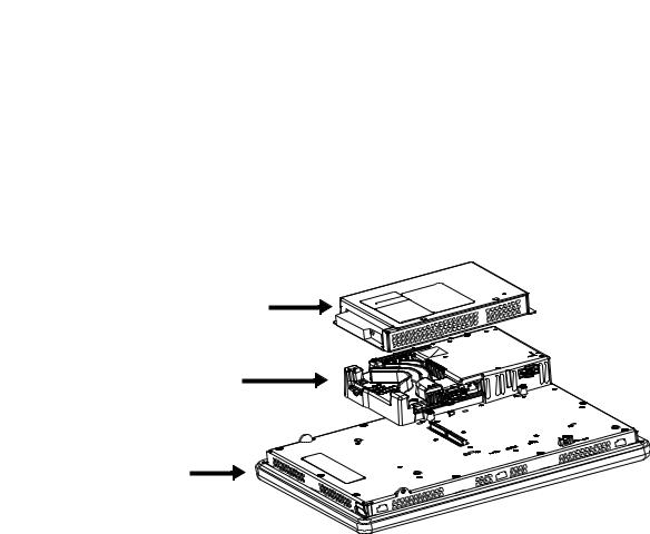
700 to 1500 Terminal Features
The larger 700 to 1500 terminals consist of modular components ordered separately or as configured terminals. The modular components consist of the following:
•Display module
•Logic module
•Optional communication module
These components provide for flexible configuration, installation, and upgrades. You can order a factory-assembled unit with a single catalog number or separate components for field installation.
3
2
1
Table 7 - Modular Components
Item |
Terminal Component |
Description |
Options for Environmental Conditions |
|
|
||
|
|
|
|
|
|
||
1 |
Display module |
Flat panel, color graphic display in four sizes with keypad, |
Display modules are also available with these |
|
|
||
|
|
touch-screen, or combination keypad/touch-screen input: |
characteristics: |
|
|
||
|
|
• |
700 (6.5 in.) |
• |
Marine-certified |
|
|
|
|
• |
1000 (10.4 in.) |
• |
Conformal-coated |
|
|
|
|
• |
1250 (12.1 in.) |
• High-bright display for outdoor use |
|
|
|
|
|
• |
1500 (15 in.) |
• |
Built-in antiglare overlay |
|
|
|
|
|
|
|
|
||
2 |
Logic module |
The logic module has these hardware features: |
Logic modules are also available with these characteristics: |
|
|
||
|
|
• Power input, AC or DC |
• |
Marine-certified |
|
|
|
|
|
• |
RS-232 serial port |
• |
Conformal-coated |
|
|
|
|
• |
Ethernet port |
|
|
|
|
|
|
• 2 USB 2.0 host ports, 1 high-speed device port |
|
|
|
|
|
|
|
• Network interface for optional communication module |
|
|
|
|
|
|
|
• 512 MB nonvolatile and 512 MB RAM memory |
|
|
|
|
|
|
|
• Secure Digital (SD) card slot |
|
|
|
|
|
|
|
• Battery-backed real-time clock |
|
|
|
|
|
|
|
• |
Status indicators |
|
|
|
|
|
|
• |
Reset switches |
|
|
|
|
|
|
• |
Single PCI slot |
|
|
|
|
|
|
|
|
|
|
||
3 |
Communication module |
Optional module for communication with these networks: |
Communication modules are also available with these |
|
|
||
|
|
||||||
|
|
• |
DH+™/DH-485 |
characteristics: |
|
|
|
|
|
• ControlNet scheduled and unscheduled |
• |
Marine-certified |
|
|
|
|
|
• |
Ethernet |
• |
Conformal-coated |
|
|
|
|
|
|
|
|
|
|
Rockwell Automation Publication 2711P-UM006C-EN-P - April 2013 |
17 |
Chapter 1 |
Overview |
|
|
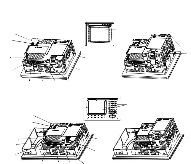
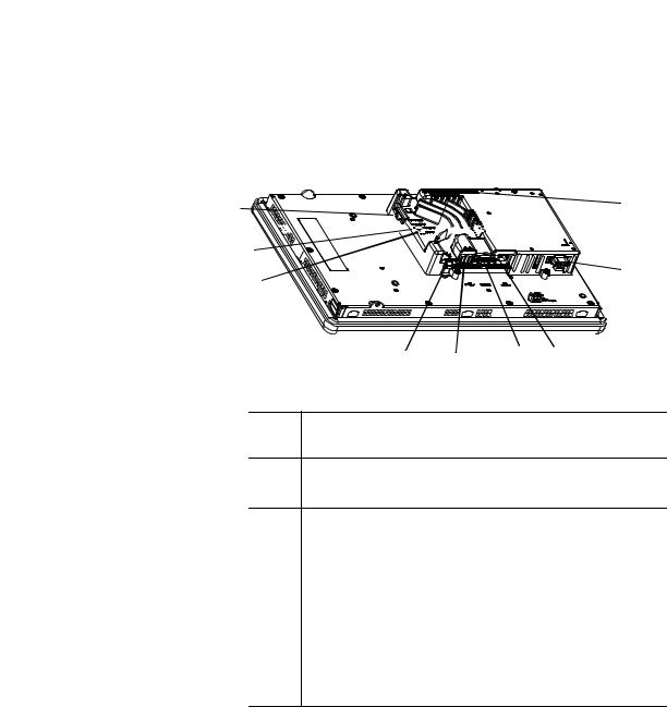
Configured Terminals
A configured terminal, ordered as a single-catalog number, has a display module and logic module.
An optional DH+/DH-485, ControlNet, or Ethernet communication module can be added later for additional network capabilities.
10 |
1 |
9


8
 2
2
7
6 |
5 |
4 |
3 |
|
|
Table 8 - Logic Module Features
Item |
Feature |
1 |
Network interface connector for optional communication module |
2AC or DC power input(1)
•Isolated 18…32V DC
•85…264V AC
3 |
Ethernet port for controller communication, 10/100 BaseT, Auto MDI/MDI-X |
4 |
RS-232 serial port for file transfers, printing, and controller communication |
|
|
5 |
Two USB 2.0 high-speed (type A) host ports for attaching USB devices including mouse, |
|
keyboard, printer, and USB drives that are hot-swappable in nonhazardous locations |
|
|
6 |
One USB 2.0 high-speed (type mini- B) device port for connecting a host computer |
|
|
7 |
Reset switch to reset the terminal without having to power on and off |
|
|
8 |
Default switch to access maintenance operations such as restoring factory defaults |
|
|
9 |
Indicators provide communication and fault status |
|
|
10 |
Secure Digital (SD) card slot supporting cat. no. 1784-SDx cards |
(1)For DC applications using AC power, an external, remote AC-to-DC power supply, cat. no. 2711P-RSACDIN, is available for DIN-rail mounting.
18 |
Rockwell Automation Publication 2711P-UM006C-EN-P - April 2013 |
Overview |
Chapter 1 |
|
|
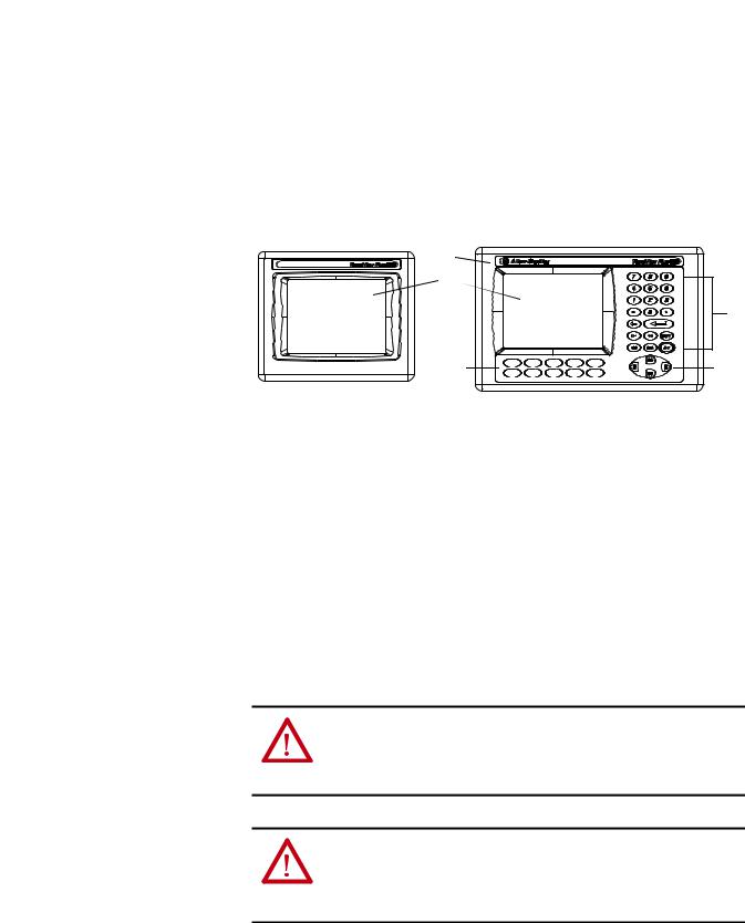
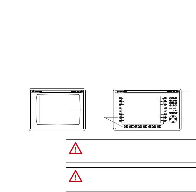
Operator Input
All 700 to 1500 display modules have TFT color, graphic displays with either keypad, touch screen, or combination keypad/touch-screen input. Common features and firmware provide for easy migration to a larger display:
•Eight-wire resistive touch screens are extremely accurate for operator interfaces. When a point on the touch screen is pressed, the layers connect and change the electrical current, which is then registered and processed.
•All keypad or combination keypad/touch-screen displays are similar except for the number of functions keys.
To meet the requirements of specific environmental conditions, high-bright displays, marine-certified displays, and conformal-coated displays are also available. Plus, you can order field replaceable bezels.
1 |
1 |


 2
2


 3 2
3 2 


5 
4
ATTENTION: Use a finger or gloved finger to operate the keypad. To operate the touch screen, use a finger, gloved-finger or plastic stylus with a minimum tip radius of 1.3 mm (0.051 in.). Using any other object or tool can damage the keypad or touch screen.
ATTENTION: Do not carry out multiple operations simultaneously. Doing so can result in unintended operation:
•Touch only one operating element on the screen with one finger at one time.
•Press only one key on the terminal at one time.
Table 9 - Display Features
Item |
Feature |
|
Description |
|
|
|
|
1 |
Replaceable ID Label |
Product identification label can be replaced with custom label. |
|
|
|
|
|
2 |
Display |
|
Analog resistive touch screen applies to touch-screen or combination |
|
|
|
keypad/touch-screen terminals. |
|
|
|
|
3 |
Numeric keypad |
0…9, –, Backspace, Enter, Left and Right tab, Shift, Esc, Ctrl, Alt keys. |
|
|
|
|
|
4 |
Navigation keys |
Use arrow keys for navigation. Use Alt+arrow to initiate these functions: |
|
|
|
|
• Alt+left arrow (Home), Alt+right arrow (End) |
|
|
|
• Alt+up arrow (Page Up), Alt+down arrow (Page Down) |
|
|
|
|
5 |
Function keys |
Keys that can be configured in the application to perform operations. For |
|
|
700 |
F1 …F10, K1…K12 |
example, F1 can be configured to navigate to another screen. |
|
1000 |
F1 …F16, K1…K16 |
Replaceable legends are available to customize the function key labels. |
|
1250 |
F1 …F20, K1…K20 |
|
|
1500 |
F1 …F20, K1…K20 |
|
|
|
|
|
Rockwell Automation Publication 2711P-UM006C-EN-P - April 2013 |
19 |

Chapter 1 Overview
|
|
400/600 Terminal Selections |
The table shows the catalog number breakdown for the 400 and 600 terminals. |
|||||
|
|
Bulletin |
Input Type |
Display Size |
Display Type |
Communication |
Power |
Operating System |
|
|
|
|
|
|
|
|
|
|
|
| |
| |
| |
| |
| |
| |
| |
|
|
2711P- |
K = Keypad |
4= 3.5 in. |
C = Color |
5 = RS-232, USB |
A = AC |
8 = Windows CE 6.0 |
|
|
|
B = Keypad and Touch |
6 = 5.7 in. |
M = Grayscale |
20 = Ethernet, RS-232, USB |
D = DC |
9 = Windows CE 6.0 with extended features |
|
|
|
T = Touch |
|
|
|
|
|
Table 10 - PanelView Plus 6 - 400 Terminals without Extended Features
|
Cat. Nos. |
Display |
Communication Ports |
USB Ports |
Input |
Memory (MB) (1) |
|||||
|
|
|
|
|
|
|
|
|
Power |
|
|
Keypad |
|
Keypad and Touch |
Size |
Type |
RS-232 |
Ethernet |
Host |
Device |
RAM |
Nonvolatile |
|
|
|
|
|
|
|
|
|
|
|
|
|
2711P-K4M5A8 |
|
— |
3.5-in. |
Grayscale |
• |
|
• |
• |
AC |
256 |
512 |
|
|
|
|
|
|
|
|
|
|
|
|
2711P-K4M5D8 |
|
— |
|
|
• |
|
• |
• |
DC |
256 |
512 |
|
|
|
|
|
|
|
|
|
|
|
|
2711P-K4M20A8 |
|
— |
|
|
• |
• |
• |
• |
AC |
256 |
512 |
|
|
|
|
|
|
|
|
|
|
|
|
2711P-K4M20D8 |
|
— |
|
|
• |
• |
• |
• |
DC |
256 |
512 |
|
|
|
|
|
|
|
|
|
|
|
|
2711P-K4C5A8 |
|
2711P-B4C5A8 |
3.5-in. |
Color |
• |
|
• |
• |
AC |
256 |
512 |
|
|
|
|
|
|
|
|
|
|
|
|
2711P-K4C5D8 |
|
2711P-B4C5D8 |
|
|
• |
|
• |
• |
DC |
256 |
512 |
|
|
|
|
|
|
|
|
|
|
|
|
2711P-K4C20A8 |
|
2711P-B4C20A8 |
|
|
• |
• |
• |
• |
AC |
256 |
512 |
|
|
|
|
|
|
|
|
|
|
|
|
2711P-K4C20D8 |
|
2711P-B4C20D8 |
|
|
• |
• |
• |
• |
DC |
256 |
512 |
|
|
|
|
|
|
|
|
|
|
|
|
(1) The terminal s support FactoryTalk View Machine Edition software, version 6.10 or later, and the Windows CE 6.0 operating system.
Table 11 - PanelView Plus 6 - 600 Terminals without Extended Features
|
Cat. Nos. |
|
Display |
Communication Ports |
USB Ports |
Input |
Memory (MB) (1) |
||||
Keypad |
Touch |
Keypad and Touch |
Size |
Type |
RS-232 |
Ethernet |
Host |
Device |
Power |
RAM |
Nonvolatile |
|
|
|
|
|
|
|
|
|
|
|
|
2711P-K6M5A8 |
2711P-T6M5A8 |
2711P-B6M5A8 |
5.7-in. |
Grayscale |
• |
|
• |
• |
AC |
256 |
512 |
|
|
|
|
|
|
|
|
|
|
|
|
2711P-K6M5D8 |
2711P-T6M5D8 |
2711P-B6M5D8 |
|
|
• |
|
• |
• |
DC |
256 |
512 |
|
|
|
|
|
|
|
|
|
|
|
|
2711P-K6M20A8 |
2711P-T6M20A8 |
2711P-B6M20A8 |
|
|
• |
• |
• |
• |
AC |
256 |
512 |
|
|
|
|
|
|
|
|
|
|
|
|
2711P-K6M20D8 |
2711P-T6M20D8 |
2711P-B6M20D8 |
|
|
• |
• |
• |
• |
DC |
256 |
512 |
|
|
|
|
|
|
|
|
|
|
|
|
2711P-K6C5A8 |
2711P-T6C5A8 |
2711P-B6C5A8 |
5.7-in. |
Color |
• |
|
• |
• |
AC |
256 |
512 |
|
|
|
|
|
|
|
|
|
|
|
|
2711P-K6C5D8 |
2711P-T6C5D8 |
2711P-B6C5D8 |
|
|
• |
|
• |
• |
DC |
256 |
512 |
|
|
|
|
|
|
|
|
|
|
|
|
2711P-K6C20A8 |
2711P-T6C20A8 |
2711P-B6C20A8 |
|
|
• |
• |
• |
• |
AC |
256 |
512 |
|
|
|
|
|
|
|
|
|
|
|
|
2711P-K6C20D8 |
2711P-T6C20D8 |
2711P-B6C20D8 |
|
|
• |
• |
• |
• |
DC |
256 |
512 |
|
|
|
|
|
|
|
|
|
|
|
|
(1) The terminals support FactoryTalk View Machine Edition software, version 6.10 or later, and the Windows CE 6.0 operating system.
Table 12 - PanelView Plus 6 - 600 Terminals with Extended Features
|
Cat. Nos. |
|
Display |
Communication |
USB Ports |
Input |
Memory (MB)(1) |
||||
Keypad |
Touch |
Keypad and Touch |
Size |
Type |
RS-232 |
Ethernet |
Host |
Device |
Power |
RAM |
Nonvolatile |
|
|
|
|
|
|
|
|
|
|
|
|
2711P-K6C5A9 |
2711P-T6C5A9 |
2711P-B6C5A9 |
5.7-in. |
Color |
• |
|
• |
• |
AC |
256 |
512 |
|
|
|
|
|
|
|
|
|
|
|
|
2711P-K6C5D9 |
2711P-T6C5D9 |
2711P-B6C5D9 |
|
|
• |
|
• |
• |
DC |
256 |
512 |
|
|
|
|
|
|
|
|
|
|
|
|
2711P-K6C20A9 |
2711P-T6C20A9 |
2711P-B6C20A9 |
|
|
• |
• |
• |
• |
AC |
256 |
512 |
|
|
|
|
|
|
|
|
|
|
|
|
2711P-K6C20D9 |
2711P-T6C20D9 |
2711P-B6C20D9 |
|
|
• |
• |
• |
• |
DC |
256 |
512 |
|
|
|
|
|
|
|
|
|
|
|
|
(1) The terminals support FactoryTalk View Machine Edition software, version 6.10 or later, and the Windows CE 6.0 operating system with extended features and file viewers.
20 |
Rockwell Automation Publication 2711P-UM006C-EN-P - April 2013 |
Overview |
Chapter 1 |
|
|
700 to 1500 Terminal Selections
The table shows the catalog number breakdown for the 700 to 1500 terminals.
Bulletin |
Input Type |
Display Size |
Display Type |
Communication (1) |
Power |
Operating System |
Special Option |
|
| |
| |
|
| |
| |
| |
| |
| |
| |
2711P- K = Keypad |
7 = 6.5 in. |
C = Color |
4 = Ethernet, RS-232 & (2) USB |
A = AC 8= Windows CE 6.0 |
K = Conformal-Coated |
|||
|
T = Touch |
10 |
= 10.4 in. |
|
|
D = DC 9 = Windows CE 6.0 with |
|
|
|
|
|
|
|
|
|
extended features |
|
|
B = Keypad/Touch |
12 |
= 12.1 in. |
|
|
|
|
|
|
|
15 |
= 15 in. |
|
|
|
|
|
(1) Optional communication modules are available as separate catalog numbers.
Table 13 - PanelView Plus 6 - 700 to 1500 Terminals without Extended Features
|
Cat. Nos. |
|
Display |
Communication |
Input |
Memory MB (1) |
|||
|
|
|
|
|
|
|
|
|
|
Keypad |
Touch |
Keypad/Touch |
Size |
Type |
RS-232 |
Ethernet |
Power |
RAM |
Nonvolatile |
|
|||||||||
|
|
|
|
|
|
|
|
|
|
700 Model |
|
|
|
|
|
|
|
|
|
|
|
|
|
|
|
|
|
|
|
2711P-K7C4D8 |
2711P-T7C4D8 |
2711P-B7C4D8 |
6.5-in. |
Color |
• |
• |
DC |
512 |
512 |
|
|
|
|
|
|
|
|
|
|
– |
2711P-T7C4D8K |
– |
|
|
• |
• |
DC |
512 |
512 |
|
|
|
|
|
|
|
|
|
|
2711P-K7C4A8 |
2711P-T7C4A8 |
2711P-B7C4A8 |
|
|
• |
• |
AC |
512 |
512 |
|
|
|
|
|
|
|
|
|
|
1000 Model |
|
|
|
|
|
|
|
|
|
|
|
|
|
|
|
|
|
|
|
2711P-K10C4D8 |
2711P-T10C4D8 |
2711P-B10C4D8 |
10.4-in |
Color |
• |
• |
DC |
512 |
512 |
|
|
|
|
|
|
|
|
|
|
2711P-K10C4A8 |
2711P-T10C4A8 |
2711P-B10C4A8 |
|
|
• |
• |
AC |
512 |
512 |
|
|
|
|
|
|
|
|
|
|
1250 Model |
|
|
|
|
|
|
|
|
|
|
|
|
|
|
|
|
|
|
|
2711P-K12C4D8 |
2711P-T12C4D8 |
2711P-B12C4D8 |
12.1-in |
Color |
• |
• |
DC |
512 |
512 |
|
|
|
|
|
|
|
|
|
|
– |
2711P-T12C4D8K |
– |
|
|
• |
• |
DC |
512 |
512 |
|
|
|
|
|
|
|
|
|
|
2711P-K12C4A8 |
2711P-T12C4A8 |
2711P-B12C4A8 |
|
|
• |
• |
AC |
512 |
512 |
|
|
|
|
|
|
|
|
|
|
1500 Model |
|
|
|
|
|
|
|
|
|
|
|
|
|
|
|
|
|
|
|
2711P-K15C4D8 |
2711P-T15C4D8 |
2711P-B15C4D8 |
15-in. |
Color |
• |
• |
DC |
512 |
512 |
|
|
|
|
|
|
|
|
|
|
2711P-K15C4A8 |
2711P-T15C4A8 |
2711P-B15C4A8 |
|
|
• |
• |
AC |
512 |
512 |
|
|
|
|
|
|
|
|
|
|
(1) The logic module supports FactoryTalk View Machine Edition software, version 6.0 or later, FactoryTalk ViewPoint software version 1.2 or later, and the Windows CE 6.0 operating system.
Rockwell Automation Publication 2711P-UM006C-EN-P - April 2013 |
21 |

Chapter 1 |
Overview |
|
|
Table 14 - PanelView Plus 6 - 700 to 1500 Terminals with Extended Features
|
Cat. Nos. |
|
Display |
Communication |
Input |
Memory (1) |
|||
|
|
|
|
|
|
|
|
|
|
Keypad |
Touch |
Keypad/Touch |
Size |
Type |
RS-232 |
Ethernet |
Power |
RAM |
Nonvolatile |
|
|||||||||
|
|
|
|
|
|
|
|
|
|
700 Model |
|
|
|
|
|
|
|
|
|
|
|
|
|
|
|
|
|
|
|
2711P-K7C4D9 |
2711P-T7C4D9 |
2711P-B7C4D9 |
6.5-in. |
Color |
• |
• |
DC |
512 MB |
512 MB |
|
|
|
|
|
|
|
|
|
|
2711P-K7C4A9 |
2711P-T7C4A9 |
2711P-B7C4A9 |
|
|
• |
• |
AC |
512 MB |
512 MB |
|
|
|
|
|
|
|
|
|
|
1000 Model |
|
|
|
|
|
|
|
|
|
|
|
|
|
|
|
|
|
|
|
2711P-K10C4D9 |
2711P-T10C4D9 |
2711P-B10C4D9 |
10.4-in |
Color |
• |
• |
DC |
512 MB |
512 MB |
|
|
|
|
|
|
|
|
|
|
2711P-K10C4A9 |
2711P-T10C4A9 |
2711P-B10C4A9 |
|
|
• |
• |
AC |
512 MB |
512 MB |
|
|
|
|
|
|
|
|
|
|
1250 Model |
|
|
|
|
|
|
|
|
|
|
|
|
|
|
|
|
|
|
|
2711P-K12C4D9 |
2711P-T12C4D9 |
2711P-B12C4D9 |
12.1-in |
Color |
• |
• |
DC |
512 MB |
512 MB |
|
|
|
|
|
|
|
|
|
|
2711P-K12C4A9 |
2711P-T12C4A9 |
2711P-B12C4A9 |
|
|
• |
• |
AC |
512 MB |
512 MB |
|
|
|
|
|
|
|
|
|
|
1500 Model |
|
|
|
|
|
|
|
|
|
|
|
|
|
|
|
|
|
|
|
2711P-K15C4D9 |
2711P-T15C4D9 |
2711P-B15C4D9 |
15-in. |
Color |
• |
• |
DC |
512 MB |
512 MB |
|
|
|
|
|
|
|
|
|
|
2711P-K15C4A9 |
2711P-T15C4A9 |
2711P-B15C4A9 |
|
|
• |
• |
AC |
512 MB |
512 MB |
|
|
|
|
|
|
|
|
|
|
(1)The logic module supports FactoryTalk View Machine Edition software, version 6.0 or later, FactoryTalk ViewPoint software version 1.2 or later, and the Windows CE 6.0 operating system with extended features and file viewers.
Accessories
Tables 15…28 list accessories for the PanelView Plus 6 terminals.
Table 15 - Display Modules - 700 to 1500 Terminals
Cat. No. |
Input Type |
Display |
Marine |
Conformal |
Built-in |
|
|
|
Certified |
Coated |
Antiglare Overlay |
|
|
|
|
|
|
700 Model |
|
|
|
|
|
|
|
|
|
|
|
2711P-RDK7C |
Keypad |
7-in. color |
|
|
|
|
|
|
|
|
|
2711P-RDK7CK |
Keypad |
|
|
• |
|
|
|
|
|
|
|
2711P-RDT7C |
Touch |
|
|
|
|
|
|
|
|
|
|
2711P-RDT7CK |
Touch |
|
|
• |
|
|
|
|
|
|
|
2711P-RDT7CM |
Touch |
|
• |
|
|
|
|
|
|
|
|
2711P-RDB7C |
Keypad/Touch |
|
|
|
|
|
|
|
|
|
|
2711P-RDB7CK |
Keypad/Touch |
|
|
• |
|
|
|
|
|
|
|
2711P-RDB7CM |
Keypad/Touch |
|
• |
|
|
|
|
|
|
|
|
1000 Model |
|
|
|
|
|
|
|
|
|
|
|
2711P-RDK10C |
Keypad |
10-4 in. color |
|
|
|
|
|
|
|
|
|
2711P-RDT10C |
Touch |
|
|
|
|
|
|
|
|
|
|
2711P-RDT10CM |
Touch |
|
• |
|
|
|
|
|
|
|
|
2711P-RDB10C |
Keypad/Touch |
|
|
|
|
|
|
|
|
|
|
2711P-RDB10CM |
Keypad/Touch |
|
• |
|
|
|
|
|
|
|
|
22 |
Rockwell Automation Publication 2711P-UM006C-EN-P - April 2013 |

Overview Chapter 1
Table 15 - Display Modules - 700 to 1500 Terminals
Cat. No. |
Input Type |
Display |
Marine |
Conformal |
Built-in |
|
|
|
Certified |
Coated |
Antiglare Overlay |
|
|
|
|
|
|
1250 Model |
|
|
|
|
|
|
|
|
|
|
|
2711P-RDK12C |
Keypad |
12.1-in. color |
|
|
|
|
|
|
|
|
|
2711P-RDK12CK |
Keypad |
|
|
• |
|
|
|
|
|
|
|
2711P-RDT12C |
Touch |
|
|
|
|
|
|
|
|
|
|
2711P-RDT12CK |
Touch |
|
|
• |
|
|
|
|
|
|
|
2711P-RDT12H(1) |
Keypad/Touch |
|
|
|
|
2711P-RDT12AG |
Touch |
|
|
|
• |
|
|
|
|
|
|
2711P-RDB12C |
Keypad/Touch |
|
|
|
|
|
|
|
|
|
|
2711P-RDB12CK |
Keypad/Touch |
|
|
• |
|
|
|
|
|
|
|
1500 Model |
|
|
|
|
|
|
|
|
|
|
|
2711P-RDK15C |
Keypad |
15-in. color |
|
|
|
|
|
|
|
|
|
2711P-RDT15C |
Touch |
|
|
|
|
|
|
|
|
|
|
2711P-RDT15AG |
Touch |
|
|
|
• |
|
|
|
|
|
|
2711P-RDB15C |
Keypad/Touch |
|
|
|
|
|
|
|
|
|
|
(1) H at end of cat. no. refers to 1250 High-bright display module.
Table 16 - Logic Modules - 700 to 1500 Terminals
Cat. No. |
Power |
Memory |
|
Communication |
Marine |
Conformal |
|
Included Software |
Input |
RAM/Nonvolatile |
|
Certified |
Coated |
|
|||
|
|
|
|
|
||||
|
|
|
|
|
|
|
|
|
Without Standard Features |
|
|
|
|
|
|
|
|
|
|
|
|
|
|
|
|
|
2711P-RP8A |
AC |
512 MB/512 MB |
• |
Ethernet |
• |
|
• Windows CE 6.0 operating system |
|
|
|
|
• |
RS-232 |
|
|
• FactoryTalk View Machine Edition runtime, |
|
2711P-RP8D |
DC |
512 MB/512 MB |
• |
|
||||
• |
Network interface for |
|
• |
version 6.0 or later |
||||
|
|
|
|
communication module |
|
|
FactoryTalk ViewPoint software, |
|
2711P-RP8DK |
DC |
512 MB/512 MB |
|
• |
• |
|||
|
|
|
version 1.2 or later |
|||||
|
|
|
|
|
|
|
|
|
|
|
|
|
|
|
|
|
|
With Extended Features |
|
|
|
|
|
|
|
|
|
|
|
|
|
|
|
|
|
2711P-RP9A |
AC |
512 MB/512 MB |
• |
Ethernet |
• |
|
• Windows CE 6.0 operating system |
|
|
|
|
• |
RS-232 |
|
|
|
with extended features and file viewers |
2711P-RP9D |
DC |
512 MB/512 MB |
• |
|
|
|||
• |
Network interface |
|
• FactoryTalk View Machine Edition runtime, |
|||||
|
|
|
|
communication module |
|
|
|
version 6.0 or later |
2711P-RP9DK |
DC |
512 MB/512 MB |
|
• |
• |
• |
||
|
|
FactoryTalk ViewPoint software, |
||||||
|
|
|
|
|
|
|
||
|
|
|
|
|
|
|
|
version 1.2 or later |
|
|
|
|
|
|
|
|
|
Table 17 - Communication Modules - 700 to 1500 Terminals
Cat. No |
|
Communication |
|
Conformal |
Marine |
|
|
||
|
|
|
|
|
|
|
|||
Ethernet |
DH+ |
DH-485 |
|
ControlNet (2) |
Coated |
Certified |
|
|
|
|
|
|
|
||||||
2711P-RN6 |
|
• |
• |
|
|
|
|
|
|
|
|
|
|
|
|
|
|
|
|
2711P-RN6K |
|
• |
• |
|
|
• |
|
|
|
|
|
|
|
|
|
|
|
|
|
2711P-RN15S |
|
|
|
|
• |
|
• |
|
|
|
|
|
|
|
|
|
|
|
|
2711P-RN15SK |
|
|
|
|
• |
• |
|
|
|
|
|
|
|
|
|
|
|
|
|
2711P-RN20(1) |
• |
|
|
|
|
|
|
|
|
|
|
|
|
|
|
|
|
||
|
|
|
|
|
|
|
|
|
|
(1)All terminals have an Ethernet port. The cat. no. 2711P-RN20 module provides an additional Ethernet port.
(2)Scheduled and unscheduled communication.
Rockwell Automation Publication 2711P-UM006C-EN-P - April 2013 |
23 |

Chapter 1 |
Overview |
|
|
Table 18 - Secure Digital (SD) Cards
Cat. No. |
Terminal Model |
Description |
|
|
|
1784-SD1 |
|
1 GB Secure Digital (SD) card |
|
|
|
1784-SD2 |
All terminals |
2 GB Secure Digital (SD) card |
|
|
|
2711C-RCSD |
|
USB to SD adapter for secure digital card (SD) |
|
|
|
Table 19 - CCFL Backlight Replacements (1)
Cat. No. |
Terminal Model |
Series |
Number of CCFL |
|
Backlights |
||||
|
|
|
||
|
|
|
|
|
2711P-RL7C |
700 |
A and B |
1 |
|
|
|
|
|
|
2711P-RL7C2 |
|
C and D |
1 |
|
|
|
|
|
|
2711P-RL10C |
1000 |
A |
1 |
|
|
|
|
||
2711P-RL10C2 |
B and C |
1 |
||
|
||||
|
|
|
|
|
2711P-RL12C |
1250 |
A and B |
2 |
|
|
|
|
||
2711P-RL12C2 |
C |
1 |
||
|
||||
|
|
|
|
|
2711P-RL15C |
1500 |
B |
2 |
|
|
|
|
|
(1) These CCFL-backlight replacement catalog numbers do not apply to LED displays.
Table 20 - Antiglare Overlays
Cat. No.(1) |
Terminal Model |
|
Operator Input |
||
|
|
|
|||
Keypad |
Touch |
Key/Touch |
|||
|
|
||||
|
|
|
|
|
|
2711P-RGB4 |
400 grayscale or color |
• |
|
• |
|
|
|
|
|
|
|
2711P-RGK6 |
600 grayscale or color |
• |
|
• |
|
|
|
|
|
||
2711P-RGT6 |
|
• |
|
||
|
|
|
|||
|
|
|
|
|
|
2711P-RGK7 |
700 color |
• |
|
• |
|
|
|
|
|
||
2711P-RGT7 |
|
• |
|
||
|
|
|
|||
|
|
|
|
|
|
2711P-RGK10 |
1000 color |
• |
|
• |
|
|
|
|
|
||
2711P-RGT10 |
|
• |
|
||
|
|
|
|||
|
|
|
|
|
|
2711P-RGK12 |
1250 color |
• |
|
• |
|
|
|
|
|
||
2711P-RGT12 |
|
• |
|
||
|
|
|
|||
|
|
|
|
|
|
2711P-RGK15 |
1500 color |
• |
|
• |
|
|
|
|
|
||
2711P-RGT15 |
|
• |
|
||
|
|
|
|||
|
|
|
|
|
|
(1) Three overlays are shipped with each catalog number.
Table 21 - Solar Visor
Cat. No. |
Terminal Model |
Description |
|
|
|
2711P-RVT12 |
1250 |
Solar visor for 1250 high-bright display module, |
|
|
cat. no. 2711P-RDT12H |
|
|
|
24 |
Rockwell Automation Publication 2711P-UM006C-EN-P - April 2013 |

Overview |
Chapter 1 |
|
|
Table 22 - Function Key Legend Kits
Cat. No. |
Terminal Model(1) |
Description |
2711P-RFK6 |
600 keypad |
|
|
|
|
2711P-RFK7 |
700 keypad |
|
|
|
|
2711P-RFK10 |
1000 keypad |
Blank legend inserts and software |
|
|
|
2711P-RFK12 |
1250 keypad |
|
|
|
|
2711P-RFK15 |
1500 keypad |
|
|
|
|
(1) Applies to keypad and keypad/touch-screen terminals.
Table 23 - Mounting Hardware
Cat. No. |
Terminal Model |
Description |
Quantity |
|
|
|
|
2711P-RTFC |
400 or 600 |
Replacement mounting levers |
8 |
|
|
|
|
2711P-RTMC |
700 to 1500 |
Replacement Mounting clips |
8 |
|
|
|
|
Table 24 - Replacement Battery
Cat. No. |
Terminal Model |
Description |
|
|
|
2711P-RY2032 |
All terminals |
Replacement CR2032 coin-cell equivalent battery |
|
|
|
Table 25 - Cables
Cat. No. |
Terminal Model |
Description |
Length |
|
|
|
|
2711C-CBL-UU02 |
700 to 1500 |
Programming cable that connects the USB device port of |
2 m (6.5 ft) |
|
|
the terminal to a USB host port of a computer |
|
|
|
|
|
6189V-USBCBL2 |
400 and 600 |
Programming cable that connects the USB device port of |
1.8 m (6 ft) |
|
|
the terminal to a USB host port of a computer |
|
|
|
|
|
Table 26 - Power Supply and Power Terminal Blocks
Cat. No. |
Terminal Model |
Description |
Quantity |
|
|
|
|
2711P-RSACDIN |
All terminals |
DIN-rail power supply, AC-to-DC, 85…265V AC, 47…63 Hz |
1 |
|
|
|
|
2711P-RVAC |
400 and 600 |
AC power terminal block |
10 |
|
|
|
|
2711P-6RSA |
|
AC module converts a DC-powered terminal to AC power |
1 |
|
|
|
|
2711-TBDC |
|
DC power terminal block |
10 |
|
|
|
|
2711P-RTBAC3 |
700 to 1500 |
AC power terminal block |
10 |
|
|
|
|
2711P-RTBDC2 |
|
DC power terminal block |
10 |
|
|
|
|
Table 27 - Bezel Replacements
Cat. No. |
Terminal Model |
|
Operator Input |
|
|
|
|
||
|
|
Keypad |
Touch |
Key/Touch |
|
|
|
|
|
2711P-RBK7 |
|
• |
|
|
|
|
|
|
|
2711P-RBT7 |
700 |
|
• |
|
|
|
|
|
|
2711P-RBB7 |
|
|
|
• |
|
|
|
|
|
Rockwell Automation Publication 2711P-UM006C-EN-P - April 2013 |
25 |

Chapter 1 |
Overview |
|
|
Table 27 - Bezel Replacements
Cat. No. |
Terminal Model |
|
Operator Input |
|
|
|
|
||
|
|
Keypad |
Touch |
Key/Touch |
|
|
|
|
|
2711P-RBK10 |
|
• |
|
|
|
|
|
|
|
2711P-RBT10 |
1000 |
|
• |
|
|
|
|
|
|
2711P-RBB10 |
|
|
|
• |
|
|
|
|
|
2711P-RBK12 |
|
• |
|
|
|
|
|
|
|
2711P-RBT12 |
1250 |
|
• |
|
|
|
|
|
|
2711P-RBT12H(1) |
|
• |
|
|
|
|
|
||
2711P-RBB12 |
|
|
|
• |
|
|
|
|
|
2711P-RBK15 |
|
• |
|
|
|
|
|
|
|
2711P-RBT15 |
1500 |
|
• |
|
|
|
|
|
|
2711P-RBB15 |
|
|
|
• |
|
|
|
|
|
(1) Applies to the cat. no. 2711P-RDT12H 1250 high-bright display module.
Table 28 - Adapter Plates
Cat. No. |
Adapts This |
To This Terminal Cutout |
|
PanelView Plus 6 Terminal |
|||
|
|
||
|
|
|
|
2711P-RAK4 |
400 keypad or keypad/touch |
PanelView Standard 550 keypad |
|
|
600 touch |
|
|
|
|
|
|
2711P-RAK6 |
600 keypad or keypad/touch |
PanelView Standard 600 keypad |
|
|
|
|
|
2711P-RAK7 |
700 keypad or keypad/touch |
PanelView Standard 900 keypad |
|
|
|
|
|
2711P-RAT7 |
700 touch |
PanelView Standard 900 touch |
|
|
|
|
|
2711P-RAK10 |
1000 keypad or keypad/touch |
PanelView 1000/1000e keypad |
|
|
|
|
|
2711P-RAT10 |
1000 touch |
PanelView 1000/1000e touch |
|
|
|
|
|
2711P-RAK15 |
1500 keypad or keypad/touch |
PanelView 1200e/1400e keypad |
|
|
|
|
|
2711P-RAT15 |
1500 touch |
PanelView 1200e/1400e touch |
|
|
|
|
|
2711P-RAK12E |
1250 keypad(1) |
PanelView 1200/1400e keypad |
|
2711P-RAT12E2 |
1250 touch(2) |
PanelView 1200 touch |
|
2711P-RAT12E |
1250 touch(2) |
PanelView 1200e/1400e touch |
|
2711P-RAK12S |
1250 keypad(1) or keypad/touch |
PanelView Standard 1400 keypad |
|
2711P-RAT12S |
1250 touch(2) |
PanelView Standard 1400 touch |
(1)Applies also to PanelView 1000/1000e keypad or keypad/touch terminals.
(2)Applies also to PanelView 1000/1000e touch terminals.
26 |
Rockwell Automation Publication 2711P-UM006C-EN-P - April 2013 |
Chapter 2
Install Terminal
Topic |
Page |
|
|
Required Circuit Parameters for USB Peripheral Devices |
29 |
|
|
Mounting Clearances |
30 |
|
|
Panel Guidelines |
30 |
|
|
Panel Cutout Dimensions |
30 |
|
|
Remove and Install the Power Terminal Block |
37 |
|
|
Mount the 400/600 Terminal in a Panel |
33 |
|
|
Mount the 700 to 1500 Terminal in a Panel |
35 |
|
|
Remove and Install the Power Terminal Block |
37 |
|
|
DC Power Connections |
38 |
|
|
AC Power Connections |
41 |
|
|
Initial Startup |
43 |
|
|
Reset the Terminal |
43 |
|
|
ATTENTION: Environment and Enclosure
This equipment is intended for use in a Pollution Degree 2 industrial environment, in overvoltage Category II applications (as defined in IEC 60664-1), at altitudes up to 2000 m (6561 ft) without derating.
The terminals are intended for use with programmable logic controllers. Terminals that are AC powered must be connected to the secondary of an isolating transformer.
This equipment is considered Group 1, Class A industrial equipment according to IEC CISPR 11. Without appropriate precautions, there may be difficulties with electromagnetic compatibility in residential and other environments due to conducted or radiated disturbances.
Korean Radio Wave Suitability Registration - When so marked this equipment is registered for Electromagnetic Conformity Registration as business equipment (A), not home equipment. Sellers or users are required to take caution in this regard.
This equipment is supplied as open-type equipment. It must be mounted within an enclosure that is suitably designed for those specific environmental conditions that will be present and appropriately designed to prevent personal injury resulting from accessibility to live parts. The interior of the enclosure must be accessible only by the use of a tool. The terminals meet specified NEMA, UL type, and IEC ratings only when mounted in a panel or enclosure with the equivalent rating. Subsequent sections of this publication may contain additional information regarding specific enclosure type ratings that are required to comply with certain product safety certifications.
In addition to this publication, see the following:
•Industrial Automation Wiring and Grounding Guidelines, publication 1770-4.1, for additional installation requirements
•NEMA Standards 250 and IEC 60529, as applicable, for explanations of the degrees of protection provided by different types of enclosure
Rockwell Automation Publication 2711P-UM006C-EN-P - April 2013 |
27 |
Chapter 2 |
Install Terminal |
|
|
North American Hazardous Location Approval
The following information applies when operating this equipment in |
Informations sur l’utilisation de cet équipement en environnements |
|||
hazardous locations. |
dangereux. |
|||
|
|
|
||
When marked, these products are suitable for use in "Class I, |
Lorqu'ils sont marqués, ces produits ne conviennent qu'à une |
|||
utilisation en environnements Classe I, Division 2, Groupes A, B, C |
||||
Division 2, Groups A, B, C, D"; Class I, Zone 2, Group IIC, Class II, |
||||
et D ; Classe I, Zone 2, Groupe IIC, Classe II, Division II, Groupes F et |
||||
Division II, Groups F, G; Class III hazardous locations and |
||||
G ; Classe III, dangereux ou non dangereux. Chaque produit est |
||||
nonhazardous locations only. Each product is supplied with |
||||
livré avec des marquages sur sa plaque d'identification qui |
||||
markings on the rating nameplate indicating the hazardous |
||||
indiquent le code de température pour les environnements |
||||
location temperature code. When combining products within a |
||||
dangereux. Lorsque plusieurs produits sont combinés dans un |
||||
system, the most adverse temperature code (lowest "T" number) |
||||
système, le code de température le plus défavorable (code " T " le |
||||
may be used to help determine the overall temperature code of the |
||||
plus faible) peut être utilisé pour déterminer le code de |
||||
system. Combinations of equipment in your system are subject to |
||||
température global du système. Les combinaisons d'équipements |
||||
investigation by the local Authority Having Jurisdiction at the time |
||||
dans le système sont sujettes à inspection par les autorités locales |
||||
of installation. |
||||
qualifiées au moment de l'installation. |
||||
|
|
|||
|
|
|
|
|
|
WARNING: EXPLOSION HAZARD |
|
AVERTISSEMENT : RISQUE D’EXPLOSION |
|
|
• Do not disconnect equipment unless power has been removed |
|
• Couper le courant ou s'assurer que l'environnement est |
|
|
or the area is known to be nonhazardous. |
|
classé non dangereux avant de débrancher l'équipement. |
|
|
• Do not disconnect connections to this equipment unless |
|
• Couper le courant ou s'assurer que l'environnement est |
|
|
power has been removed or the area is known to be |
|
classé non dangereux avant de débrancher les connecteurs. |
|
|
nonhazardous. |
|
• La substitution de composants peut rendre cet équipement |
|
|
• Substitution of components may impair suitability for Class I, |
|
inadapté à une utilisation en environnement de Classe I, |
|
|
Division 2. |
|
Division 2 |
|
|
• Peripheral equipment must be suitable for the location in |
|
• Les équipements périphériques doivent s'adapter à |
|
|
which it is used. |
|
l'environnement dans lequel ils sont utilisés. |
|
|
• The battery or real-time clock module in this product must |
|
• La batterie ou le module de l'horloge en temps réel de ce |
|
|
only be changed in an area known to be nonhazardous. |
|
produit doit être changé(e) uniquement dans un |
|
|
• All wiring must be in accordance with Class I, Division 2, Class |
|
environnement classé sans risque. |
|
|
II, Division 2, or Class III, Division 2 wiring methods of Articles |
|
• Tous les systèmes de câblage doivent être de Classe I, |
|
|
501, 502 or 503, as appropriate, of the National Electrical Code |
|
Division 2, Classe II, Division 2, ou Classe III, Division 2, |
|
|
and/or in accordance with Section 18-1J2 of the Canadian |
|
conformément aux méthodes de câblage indiquées dans |
|
|
Electrical Code, and in accordance with the authority having |
|
les Articles 501, 502 ou 503 du National Electrical Code |
|
|
jurisdiction. |
|
(Code Electrique National) et/ou conformément à la Section |
|
|
|
|
18-1J2 du Canadian Electrical Code (Code Electrique |
|
|
|
|
Canadien), et en fonction de l'autorité de jurisdiction. |
|
|
|
|
|
|
Table 29 - Temperature Codes - PanelView Plus 6 Terminals
|
|
Terminal Model |
Input Power |
Temperature Code |
Description |
|
|
||||
|
|
|
|
|
|
|
|
400 and 600 terminals |
DC |
T4 |
Do not install terminals rated T4 in environments where atmospheric gases have ignition |
|
|
||||
|
|
|
|
|
temperatures less than 135 °C (275 °F). |
|
|
|
AC |
T4 |
|
|
|
|
|
||
|
|
|
|
|
|
|
|
700 to 1500 terminals |
DC |
T4 |
|
|
|
|
|||
|
|
|
|
|
|
|
|
|
AC |
T3 |
Do not install terminals rated T3 in environments where atmospheric gases have ignition |
|
|
|
|||
|
|
|
|
|
temperatures less than 200 °C (392 °F). |
|
|
|
|
|
|
28 |
Rockwell Automation Publication 2711P-UM006C-EN-P - April 2013 |
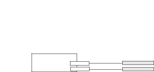
Install Terminal |
Chapter 2 |
|
|
Required Circuit Parameters for USB Peripheral Devices
The terminals contain one or two USB host ports that comply with hazardous location environments. Field-wiring compliance requirements are provided in compliance with the National Electrical Code, Article 500.
Figure 4 - PanelView Plus 6 Terminals Control Drawing
Associated Nonincendive Field-wiring Apparatus
PanelView Plus 6 Host Product
Nonincendive
Field-Wiring Apparatus
USB Host Port
USB Host Port
USB Peripheral Device
USB Peripheral Device
PanelView Plus 6 terminals provide one or two separately-powered USB host ports. Table 30 defines the circuit parameters of the USB host ports.
Table 30 - Circuit Parameters for USB Host Ports
Parameter |
Value |
Parameter Definition |
|
|
|
|
|
V oc (USB) |
5.25V DC |
Open circuit voltage of the host USB port. |
Vmax (peripheral) ≥ Voc (USB), |
|
|
The maximum applied voltage rating, Vmax (peripheral), of the USB peripheral device must be greater than |
as appropriate |
|
|
or equal to Voc (USB). |
|
I sc (USB) |
1.68 A |
Maximum output current of the host USB port. |
Imax (peripheral) ≥ I sc (USB) |
|
|
The maximum current, Imax (peripheral), to which each USB peripheral device can be subjected must be |
|
|
|
greater than or equal to I sc (USB). |
|
C a (USB) |
10 μF |
This value is the maximum total capacitance that can be connected to the USB host port. The total |
Ci (peripheral) + Ccable(USB) ≤ Ca (USB) |
|
|
capacitance of the USB peripheral device and its associated cable must not exceed the indicated value. |
|
|
|
The maximum total capacitance, Ci (peripheral), and cable capacitance of the separate USB peripheral device |
|
|
|
must be less that or equal to Ca (USB). |
|
L a (USB) |
15 μH |
This value is the maximum total inductance that can be connected to the USB host port. The total |
Li (peripheral) + Lcable ≤ La (USB) |
|
|
inductance of the USB peripheral device and its associated cable must not exceed the indicated value. |
|
|
|
The maximum total inductance, Li (peripheral), and cable inductance of the separate USB peripheral device |
|
|
|
must be less than or equal to La (USB). |
|
Application Information
Per the National Electrical Code, the circuit parameters of associated field-wiring apparatus for use in hazardous locations must be coordinated with the host product such that their combination remains nonincendive. PanelView Plus 6 terminals and the USB peripheral devices must be treated in this manner.
The USB peripheral devices and their associated cabling must have circuit parameters with the limits given in Table 30 for them to remain nonincendive when used with the PanelView Plus 6 USB host port.
If cable capacitance and inductance are not known, use the following values from ANSI/ISA-RP 12.06.01-2003:
Ccable = 197 pF/m (60 pF/ft)
Lcable = 0.7 μH/m (0.20 μH/ft)
Nonincendive field-wiring must be wired and separated in accordance with 501.10(B)(3) of the National Electrical Code (NEC) ANSI/NFPA 70 or other local codes as applicable. This associated nonincendive field-wiring apparatus has not been evaluated for use in combination with another associated nonincendive field-wiring apparatus.
Rockwell Automation Publication 2711P-UM006C-EN-P - April 2013 |
29 |

Chapter 2 |
Install Terminal |
|
|
Mounting Clearances
Panel Guidelines
Panel Cutout Dimensions
Plan for adequate space around the terminal, inside the enclosure, for ventilation and connections. Consider heat produced by other devices in the enclosure. The ambient temperature around the terminal must be 0…55 °C (32…131 °F).
Table 31 - Minimum Required Clearances
Product Area |
Minimum Clearance |
|
|
Top |
51 mm (2 in.) |
|
|
Bottom |
102 mm (4 in.) |
|
|
Side |
25 mm (1 in.) |
|
|
Back |
0 mm (0 in.) |
|
|
A clearance of 102 mm (4 in.) is sufficient on the side of the terminal to insert and remove an SD card, and on the bottom of terminal for connections.
The terminals are panel-mounted devices intended to mount in the door or wall of a NEMA rated, UL Type rated, or IP rated enclosure:
•Supporting panels must have a mounting thickness of 1.5…4.8 mm (0.060…0.188 in.).
•The material strength and stiffness of the panel must be sufficient to hold the terminal and maintain an appropriate seal against water and dust.
•The panel surface must be flat and free of imperfections to maintain an adequate seal and NEMA and UL Type ratings.
Use the full size template shipped with your terminal to mark the panel cutout dimensions.
Table 32 - Panel Cutout Dimensions
Terminal |
Input Type |
Height, mm (in.) |
Width, mm (in.) |
|||
|
|
|
|
|
|
|
400 |
Keypad or keypad/touch |
123 |
(4.86) |
156 |
(6.15) |
|
|
|
|
|
|
|
|
600 |
Keypad or keypad/touch |
142 |
(5.61) |
241 |
(9.50) |
|
|
|
|
|
|
||
Touch |
123 |
(4.86) |
156 |
(6.15) |
||
|
||||||
|
|
|
|
|
|
|
700 |
Keypad or keypad/touch |
167 |
(6.57) |
264 |
(10.39) |
|
|
|
|
|
|
||
Touch |
154 |
(6.08) |
220 |
(8.67) |
||
|
||||||
|
|
|
|
|
|
|
1000 |
Keypad or keypad/touch |
224 |
(8.8) |
375 |
(14.75) |
|
|
|
|
|
|
||
Touch |
224 |
(8.8) |
305 |
(12.00) |
||
|
||||||
|
|
|
|
|
|
|
1250 |
Keypad or keypad/touch |
257 |
(10.11) |
390 |
(15.35) |
|
|
|
|
|
|
||
Touch(1) |
257 |
(10.11) |
338 |
(13.29) |
||
|
||||||
1500 |
Keypad or keypad/touch |
305 |
(12.00) |
419 |
(16.50) |
|
|
|
|
|
|
||
Touch |
305 |
(12.00) |
391 |
(15.40) |
||
|
||||||
|
|
|
|
|
|
|
(1) Also applies to high-bright display module, cat. no. 2711P-RDT12H.
30 |
Rockwell Automation Publication 2711P-UM006C-EN-P - April 2013 |
Loading...