


AutoMax
Processor Module
M/N 57C430A
M/N 57C431
M/N 57C435
Instruction Manual J 3650 6

The information in this user's manual is subject to change without notice.
WARNING
ONLY QUALIFIED PERSONNEL FAMILIAR WITH THE CONSTRUCTION AND OPERATION OF THE CONTROLLED EQUIPMENT SHOULD INSTALL, ADJUST, OPERATE, OR SERVICE THIS EQUIPMENT. READ AND UNDERSTAND THIS MANUAL AND OTHER MANUALS APPLICABLE TO YOUR INSTALLATION. FAILURE TO OBSERVE THIS PRECAUTION COULD RESULT IN BODILY INJURY.
WARNING
INSERTING OR REMOVING THIS MODULE OR ITS CONNECTING CABLES MAY RESULT IN UNEXPECTED MACHINE MOTION. POWER TO THE MACHINE SHOULD BE TURNED OFF BEFORE INSERTING OR REMOVING THE MODULE OR ITS CONNECTING CABLES. FAILURE TO OBSERVE THESE PRECAUTIONS COULD RESULT IN BODILY INJURY.
CAUTION: This module contains static sensitive components. Careless handling can cause severe damage. Do not touch the connectors on the back of the module. When not in use, the module should be stored in an anti static bag. The plastic cover should not be removed. Failure to observe this precaution could result in damage to or destruction of equipment.
Motorolat 68010 and 68020 are trademarks of Motorola, Inc. A Bt is a trademark of Allen Bradley Corporation.
IBMt is a trademark of International Business Machines, Inc. Modbust is a trademark of Gould, Inc.
Multibust is a trademark of Intel Corporation.
Reliancer and AutoMaxr are registered trademarks of Reliance Electric Company /or its subsidiaries.
E Copyright Reliance Electric Industrial Company 1996.
Table of Contents
1.0 Introduction . . . . . . . . . . . . . . . . . . . . . . . . . . . . . . . . . . . . . . . . . . . . . . . 1.1
1.1 Additional Information . . . . . . . . . . . . . . . . . . . . . . . . . . . . . . . . . . . . 1 2 1.2 Related Hardware and Software . . . . . . . . . . . . . . . . . . . . . . . . . . . 1 2 1.3 Compatibility with Earlier Versions . . . . . . . . . . . . . . . . . . . . . . . . . 1 3
2.0 Mechanical/Electrical Description . . . . . . . . . . . . . . . . . . . . . . . . . . . 2.1
2.1 Mechanical Description . . . . . . . . . . . . . . . . . . . . . . . . . . . . . . . . . . . 2 1
2.2 Electrical Description . . . . . . . . . . . . . . . . . . . . . . . . . . . . . . . . . . . . . 2 3
3.0 Installation . . . . . . . . . . . . . . . . . . . . . . . . . . . . . . . . . . . . . . . . . . . . . . . . 3.1
3.1 Wiring . . . . . . . . . . . . . . . . . . . . . . . . . . . . . . . . . . . . . . . . . . . . . . . . . . 3 1
3.2 Initial Installation . . . . . . . . . . . . . . . . . . . . . . . . . . . . . . . . . . . . . . . . . 3 1
3.3 Module Replacement . . . . . . . . . . . . . . . . . . . . . . . . . . . . . . . . . . . . . 3 3
3.4 On Board Battery Replacement . . . . . . . . . . . . . . . . . . . . . . . . . . . . 3 4
3.5 Processor Module Diagnostics . . . . . . . . . . . . . . . . . . . . . . . . . . . . 3 5
3.5.1 Power Up Diagnostics . . . . . . . . . . . . . . . . . . . . . . . . . . . . . . 3 5
3.5.2 Run Time Diagnostics . . . . . . . . . . . . . . . . . . . . . . . . . . . . . . 3 5
4.0 Programming . . . . . . . . . . . . . . . . . . . . . . . . . . . . . . . . . . . . . . . . . . . . . . 4.1
4.1 Loading the Operating System . . . . . . . . . . . . . . . . . . . . . . . . . . . . 4 1 4.2 Accessing Processor Ports . . . . . . . . . . . . . . . . . . . . . . . . . . . . . . . . 4 3 4.3 Programmable Tick Rate . . . . . . . . . . . . . . . . . . . . . . . . . . . . . . . . . 4 4 4.4 Restrictions . . . . . . . . . . . . . . . . . . . . . . . . . . . . . . . . . . . . . . . . . . . . . 4 5 4.4.1 Number of Processors in a Rack . . . . . . . . . . . . . . . . . . . . . 4 5 4.4.2 Rack Slot Restrictions . . . . . . . . . . . . . . . . . . . . . . . . . . . . . . 4 5
4.4.3 Use with the DCS5000 M/N 57C407 Processor Module
or the 57C430 Processor Module . . . . . . . . . . . . . . . . . . . . 4 5 4.4.4 Ethernet Commands . . . . . . . . . . . . . . . . . . . . . . . . . . . . . . . 4 5
5.0 Diagnostics and Troubleshooting . . . . . . . . . . . . . . . . . . . . . . . . . . . . 5.1
5.1 The •OK" LED Is Off . . . . . . . . . . . . . . . . . . . . . . . . . . . . . . . . . . . . . . 5 1 5.2 The •BAT. OK" LED Is Off . . . . . . . . . . . . . . . . . . . . . . . . . . . . . . . . . 5 2 5.3 BUS ERROR . . . . . . . . . . . . . . . . . . . . . . . . . . . . . . . . . . . . . . . . . . . . 5 3 5.4 Common Memory Module Diagnostic Failure . . . . . . . . . . . . . . . . 5 6 5.5 Incorrect Data . . . . . . . . . . . . . . . . . . . . . . . . . . . . . . . . . . . . . . . . . . . 5 7
I
Appendices
Appendix A
Technical Specifications . . . . . . . . . . . . . . . . . . . . . . . . . . . . . . . . . . . . . . A 1
Appendix B
Module Block Diagram . . . . . . . . . . . . . . . . . . . . . . . . . . . . . . . . . . . . . . B 1
Appendix C
Connecting the AutoMax Processor to the Personal Computer . . . . C 1
Appendix D
Diagnostic LED Error Codes . . . . . . . . . . . . . . . . . . . . . . . . . . . . . . . . . . D 1
Appendix E
Run Time LED Error Codes . . . . . . . . . . . . . . . . . . . . . . . . . . . . . . . . . . . E 1
Appendix F
Using Modems with AutoMax Systems . . . . . . . . . . . . . . . . . . . . . . . . . F 1
II
List of Figures
Figure 2.1 Processor Module Faceplate . . . . . . . . . . . . . . . . . . . . . . . . . . . 2 2 Figure 2.2 Typical RS 232C Circuit . . . . . . . . . . . . . . . . . . . . . . . . . . . . . . . . 2 3
Figure 3.1 Rack Slot Numbers . . . . . . . . . . . . . . . . . . . . . . . . . . . . . . . . . . . 3 2
Figure 4.1 Specifying the SETUP Parameter in an OPEN Statement . . . 4 4
III
fadfdfdasfdsfdsdsdfdsfdsfdsfsdfdsa dfdsfdsfdfdsfdsfsadfda
fdfaddfdd

1.0 INTRODUCTION
The products described in this instruction manual are manufactured by Reliance Electric Industrial Company. The Automax Processor module plugs into the backplane of an AutoMax rack and executes application programs which in turn control other AutoMax modules in the system. The M/N 57C430A and 57C431 Processor modules are based on the Motorola 68010 16 bit microprocessor. The M/N 57C435 Processor module is based on the Motorola 68020 32 bit microprocessor. All three Processors are programmed using three high level application languages: BASIC, Control Block and Ladder Logic.
The Processor modules have the following memory/speed configurations:
Model |
CPU Speed |
Memory |
M/N 57C430A AutoMax |
8 mHz |
256K Parity RAM |
6010 Processor module |
|
|
M/N 57C431 AutoMax |
8 mHz |
512K Parity RAM |
6011 Processor module |
|
|
M/N 57C435 AutoMax |
25 mHz |
512K Parity RAM |
7010 Processor module |
|
|
Up to four AutoMax Processor modules can be used in a rack (M/N 57C331, M/N 57C332 or M/N 57C334) to increase the processing capability and the total memory available for application tasks. M/N 57C430A, 57C431, and 57C435 Processors can be used in the same rack. M/N 57C430A Processors make 135K 150K available for application programs depending on which operating system is loaded onto the Processor. M/N 57C431 and 57C435
Processors make 300K available for application programs, regardless of which operating system is loaded onto the Processor. Multiple Processors in a rack require the use of the Common Memory module (M/N 57C413 or M/N 57C423) for bus arbitration and sharing of system wide information. The Common Memory module can also be used with a single Processor module to make available an additional 128K bytes of memory for common, i.e., system wide, variables.
An on board lithium battery and a super capacitor protect the Processor module from power failures. Should the system lose power, the on board battery of the M/N 57C430A or 57C431 Processor can maintain the contents of RAM for a minimum of 42 days. The onboard battery of the M/N 57C435 Processor can maintain the contents of RAM for a minimum of 186 days.
The remainder of this manual describes the functions and specifications of the module. It also includes a detailed overview of installation and servicing procedures.
The thick black bar shown at the right hand margin of this page will be used throughout this instruction manual to signify new or revised text or figures.
1 1

1.1Additional Information
You should be familiar with the following related publications to use the AutoMax Processor correctly:
DJ 3616 1 Kermit Communications Software Instruction Manual
DJ 3618 Norton Editor Instruction Manual
DJ 3636 Common Memory Module Instruction Manual
DJ 3649 AutoMax Configuration Task Manual
DJ 3675 AutoMax Enhanced Basic Language Instruction Manual
DJ 3676 AutoMax Control Block Language Instruction Manual
DJ 3677 AutoMax Ladder Logic Language Instruction Manual
DJ2 3093 AutoMax Enhanced Ladder Editor
DJ2 3094 AutoMax Enhanced Ladder Language Reference
DYour ReSource AutoMax Executive Software Loading Instructions
DYour ReSource AutoMax Programming Executive Instruction Manual
DIEEE 518 Guide for The Installation of Electrical Equipment to Minimize Electrical Noise Inputs to Controllers
DYour personal computer and DOS operating system manual(s).
DOther instruction manuals applicable to your hardware configuration
1.2Related Hardware and Software
M/N 57C430A contains one 256K AutoMax Processor module. M/N 57C431 contains one 512K AutoMax Processor module. M/N 57C435 contains one 512K AutoMax Processor module. The
Processor module is used with the following hardware and software, which can be purchased separately:
1.IBM compatible personal computer running DOS V3.1 or later.
2.ReSource AutoMax Programming Executive software (various model numbers).
3.M/N 61C127 RS 232C ReSource Interface Cable. This cable is used to connect the personal computer to the Processor module. If you wish, you may also build your own cable using the pin description found in Appendix C.
4.M/N 57C413B, 57C423 Common Memory module. This module is used when there is more than one Processor in the rack.
5.RS 232C cable used for communicating with other devices through the Processor ports in the rack not reserved for connection to the personal computer. If you intend to use these ports, you will need to build your own cable using the pin description found in Appendix C.
6.M/N 57C331, 57C332 or 57C334 AutoMax Panel Mount Rack.
7.M/N 57C491, M/N 57C493, or M/N 57C494 AutoMax Power Supply Module.
1 2

8.M/N 57C385 AutoMax Replacement Battery. Note that the Processor module comes equipped with one (1) battery.
9.M/N 57C404A Network Communications module. This module is used to connect racks together as a network and supports communication with all racks on the network that contain 57C404A modules through a single Processor module. M/N 57C404 can be used to connect racks on a network; however, you cannot communicate over the network to the racks that contain M/N 57C404 Network modules. You must instead connect directly to the Processors in these racks.
1.3Compatibility with Earlier Versions
AutoMax Processor module M/N 57C430A, M/N 57C431, and M/N 57C435 are not compatible with Version 1.0 of the AutoMax Programming Executive software (M/N 57C304 57C307).
Processor module M/N 57C430A and M/N 57C431 require Version 2.0 or later of the AutoMax Programming Executive software.
M/N 57C435 requires Version 3.1 or later of the AutoMax Programming Executive software. M/N 57C430 cannot co exist in the same rack with M/N 57C430A, 57C431, or 57C435.
AutoMax Programming |
Compatible |
Executive Software |
Processor Module |
Version 1.0 |
|
M/N 57C304, 57C305 |
M/N 57C430 |
M/N 57C306, 57C307 (updates) |
M/N 57C430 |
Version 2.0 |
|
M/N 57C390, 57C391 |
M/N 57C430A |
M/N 57C392, 57C393 (updates) |
M/N 57C430A |
Version 2.1D |
|
M/N 57C391 |
M/N 57C430A |
|
M/N 57C431 |
|
M/N 57C435 |
M/N 57C393 (update) |
M/N 57C430A |
|
M/N 57C431 |
|
M/N 57C435 |
Version 3.0 |
|
M/N 57C395 |
M/N 57C430A |
M/N 57C397 (update) |
M/N 57C430A |
Version 3.1 |
|
M/N 57C395 |
M/N 57C430A |
|
M/N 57C431 |
|
M/N 57C435 |
M/N 57C397 (update) |
M/N 57C430A |
|
M/N 57C431 |
|
M/N 57C435 |
Version 3.3 and later* |
|
M/N 57C395 |
M/N 57C430A |
|
M/N 57C431 |
|
M/N 57C435 |
M/N 57C397 (update) |
M/N 57C430A |
|
M/N 57C431 |
*Note that if you are using the AutoMax Programming Executive for drive control applications, the Universal Drive Controller module (B/M 57552) is supported only in Version 3.3 and later of the Programming Executive software.
1 3
fadfdfdasfdsfdsdsdfdsfdsfdsfsdfdsa dfdsfdsfdfdsfdsfsadfda
fdfaddfdd
2.0 MECHANICAL/ELECTRICAL DESCRIPTION
The following is a description of the faceplate LEDs, field termination connectors, and electrical characteristics of the field connections.
2.1Mechanical Description
The Processor module is a printed circuit board assembly that plugs into the backplane of the DCS 5000/AutoMax rack. It consists of the printed circuit board, a faceplate, and a protective enclosure. The faceplate contains tabs at the top and bottom to simplify removing the module from the rack. On the back of the module are two edge connectors that connect to the system backplane. Module dimensions are listed in Appendix A.
The faceplate of the Processor module contains two independently isolated 25 pin •D" shell connectors for RS 232C serial I/O links. The upper port (labeled •PROGRAMMER/PORT B") of the leftmost Processor in the rack is reserved for connection to the personal computer only. The personal computer can communicate with all Processors in the rack through this connection.
All remaining Processor module ports (both those labeled •PROGRAMMER/PORT B" and •PORT A") are available for use by application tasks running on the respective Processors. Refer to figure 2.1 for the Processor module faceplate and Appendix C for a pin description.
2 1

AutoMax |
AutoMax |
AutoMax |
6010 Processor |
6011 Processor |
7010 Processor |
57C430A |
57C431 |
57C435 |
BAT.OK BAT.OK BAT.OK
1ST |
1ST |
1ST |
OK |
OK |
OK |
2ND |
2ND |
2ND |
PROGRAMMER / PORT B |
PROGRAMMER / PORT B |
PROGRAMMER / PORT B |
PORT A |
PORT A |
PORT A |
M/N 57C430A |
M/N 57C431 |
M/N 57C435 |
6010 Processor |
6011 Processor |
7010 Processor |
256K |
512K |
512K |
Figure 2.1 Processor Module Faceplate
2 2

The faceplate contains two green status lights and two seven segment LEDs used for diagnostic purposes. The upper status light, labeled •BAT. OK", indicates whether the on board battery is providing sufficient voltage to retain the contents of RAM (ON) or should be replaced (OFF). See 3.4 for directions on replacing the battery and Appendix A for battery specifications. The lower status light, labeled •OK", indicates whether the board is operational (ON) or should be replaced (OFF).
Five pre assigned variables are available for use in all application tasks to test the status of the on board battery. These common boolean variables will have the value 1 if the battery is functional and 0 if the battery is not functional. The variables are named according to the Processor whose battery is being tested. BATTERYSTATUS0@ is used for the Processor in slot 0. BATTERYSTATUS1@ is used for the Processor in slot 1, etc. up to slot 4.
See 3.5.1 and 3.5.2 for more information about the two seven segment LEDs on the Processor.
2.2Electrical Description
The Processor module contains a local watchdog timer which must be reset within a specified interval or the Processor will shut down and all I/O modules will be reset (initialized to 0, FALSE, or OFF). Byte parity is supported for all backplane address and data lines.
The super capacitor on the Processor module can be charged to more than 90% of its rated capacity in approximately 15 minutes and is typically capable of retaining the contents of RAM memory for approximately 10 hours should the •BAT. OK" light go out and power is removed from the Processor.
The Processor serial ports support full modem control. RS 232C signals have 450V isolation to logic common. Refer to figure 2.1 for a typical circuit diagram.
1 |
2 |
|
XMIT |
+5V |
|
|
|
|
OPTO ISOLATOR |
|
|
|
GND |
|
|
|
1 |
2 |
+5V |
|
|
|
|
|
OPTO ISOLATOR |
|
|
|
|
|
RECV |
|
GND |
|
|
Figure 2.2 Typical RS 232C Circuit
Refer to 4.2 for more information on the characteristics of the
Processor ports available to the user through application tasks.
2 3
fadfdfdasfdsfdsdsdfdsfdsfdsfsdfdsa dfdsfdsfdfdsfdsfsadfda
fdfaddfdd

3.0 INSTALLATION
This section describes how to install and replace the Processor module and the on board battery. M/N 57C430A and M/N 57C431 can be installed in the same rack.
DANGER
THE USER IS RESPONSIBLE FOR CONFORMING WITH THE NATIONAL ELECTRICAL CODE AND ALL OTHER APPLICABLE LOCAL CODES. WIRING PRACTICES, GROUNDING, DISCONNECTS, AND OVER.CURRENT PROTECTION ARE OF PARTICULAR IMPORTANCE. FAILURE TO OBSERVE THIS PRECAUTION CAN RESULT IN SERIOUS BODILY INJURY OR LOSS OF LIFE.
3.1Wiring
To reduce the possibility of electrical noise interfering with the proper operation of the control system, exercise care when installing the wiring from the system to the external devices. For detailed recommendations refer to IEEE 518.
3.2Initial Installation
Use the following procedure to install the module:
Step 1. Turn off power to the system.
Step 2. If one or both of the RS 232C ports on the Processor are to be used by application tasks for serial communication with devices other than the personal computer, use shielded RS 232 cables. Cable connectors must be equipped with EMI/RFI shielded cable clamps attached to the cable shield. The cable shield must be grounded at one end. The cable length must be in accordance with the RS 232 specification. Be sure to label the connector so that it can be easily reconnected later should it ever need to be removed. A pin description can be found in Appendix C.
Step 3. Take the module out of its shipping container. Take it out of the anti static bag, being careful not to touch the connectors on the back of the module.
Step 4. Activate the on board battery. When viewing the Processor module from the front, you can access the battery through the opening in the right wall portion of the Processor's protective enclosure. Activate the battery by taking it out of its holder and removing the tape that covers it. Replace the battery in its holder. Make certain that the battery is facing in the proper direction, i.e., the end marked •+" on the battery is facing the end marked •+" on the battery holder.
Note that the battery will begin to charge the super capacitor as soon as the battery is replaced in its holder. For maximum battery life, you should not remove
3 1
the tape from the battery unless you intend to turn power on to the module immediately.
If you are in a programming •check out" mode during which power may be left off for extended periods of time, you may wish to leave the tape on the battery and use the super capacitor for backup instead. The super capacitor will typically provide 10 hours of backup. Using the super capacitor for this purpose will extend the life of the battery.
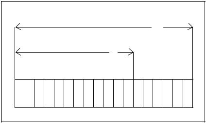
Step 5. Insert the module into the desired slot in the rack. In a single Processor configuration, you can insert the Processor in any slot 0-4. If the rack will contain multiple Processors, they can only be placed in slots 1-4. In this configuration, slot 0 is reserved for the Common Memory module. Refer to figure 3.1.
Typical 16 Slot Rack
16
Typical 10 Slot Rack
10
P/S |
0 |
1 |
2 |
3 |
4 |
5 |
6 |
7 |
8 |
9 |
10 |
11 |
12 |
13 |
14 |
15 |
Figure 3.1 Rack Slot Numbers
Step 6. Using a screwdriver, attach cable M/N 61C127 (or your own cable, built according to directions in Appendix C), to the port labeled •PROGRAMMER/PORT B" on the leftmost Processor. Attach the cable from step #2 above to ports being used to communicate with other devices.
Step 7. Turn on power to the system. The module will automatically execute its power up diagnostics. See 3.5.1 for more information. When diagnostics are complete, the seven segment LEDs on the faceplate of the leftmost Processor module will display •LO", reading top to bottom. Code •LO" means that the operating system needs to be loaded onto the Processors in the rack. See 4.1 for instructions on loading the operating system. The LEDs on all other Processor modules in the rack should be blank. The green •OK" light on all Processors should be lit. The •BAT. OK" light on all Processors should also be lit if the tape was removed from the batteries.
Step 8. Load the operating system using the directions in 4.1.
3 2
3.3Module Replacement
When you replace the Processor module in a single Processor rack, you will need to re load the operating system and all application tasks unless the new Processor already has the operating system loaded on it and the contents of RAM are valid. In this case, you will need to load the application tasks only.
In a multiple Processor rack, if your replacement Processor does not already have an operating system and valid RAM, you will have to re load the operating system and all application tasks to all Processors in the rack. If the new Processor has an operating system, you need only load the application tasks that you want to run on that particular Processor.
Use the following procedure to replace a Processor module:
Step 1. Turn off power to the system. All power to the rack, as well as all power to the wiring leading to the module, should be off.
Step 2. Use a screwdriver to loosen the screws holding the RS 232C connectors to the Processor. Detach the connectors from the module.
Step 3. Loosen the screws that hold the module in the rack. Remove the module from the slot in the rack.
Step 4. Place the module in the anti static bag it came in, being careful not to touch the connectors on the back of the module. Place the module and the anti static bag in the cardboard shipping container.
Step 5. Take the new module out of the anti static bag, being careful not to touch the connectors on the back of the module.
Step 6. Activate the battery by taking it out of its holder and removing the tape that covers it. Replace the battery in its holder. Make certain that the battery is facing in the proper direction, i.e., the end marked •+" on the battery is facing the end marked •+" on the battery holder.
Step 7. Insert the module into the correct slot in the rack. Use a screwdriver to secure the module into the slot.
Step 8. Attach the RS 232C cable connector(s) to the mating half on the module. Make certain that the connector is the proper one for this module. Use a screwdriver to secure the connector to the module.
Step 9. Turn on power to the system. The module will automatically execute its power up diagnostics. At the completion of its diagnostics, the seven segment LEDs on the faceplate should display •LO" if this is the only Processor module in the rack or the leftmost Processor in a multi Processor configuration and there is no operating system on the Processor. The LEDs on all other Processor modules should be blank. The green •OK" light should be lit, and the •BAT. OK" should be lit if the tape was removed from the battery.
Step 10. Load the operating system using the directions in 4.1.
3 3
3.4On.Board Battery Replacement
WARNING
THE BATTERY USED WITH THIS DEVICE MAY PRESENT A HAZARD IF MISTREATED. DO NOT RECHARGE, DISASSEMBLE, HEAT ABOVE 100_C (212_F), INCINERATE, OR SWALLOW. REPLACE BATTERY WITH RELIANCE ELECTRIC M/N 57C385 ONLY. DISPOSE OF USED BATTERY PROMPTLY. FAILURE TO OBSERVE THIS PRECAUTION COULD RESULT IN BODILY INJURY.
See section 5.2 for a list of the possible reasons that the •BAT. OK" light on the Processor faceplate can shut off. If you need to replace the battery, the super capacitor will provide a typical 10 hours of back up power between the time the •BAT. OK" light goes off and power is removed from the rack, and the time you insert and activate the new battery. If you replace the battery within this time limit, you will not need to re load the operating system and application tasks. Complete battery specifications can be found in Appendix A.
Use the following procedure to replace the battery on the Processor module.
Step 1. Turn off power to the system. All power to the rack, as well as all power to the wiring leading to the module, should be off.
Step 2. Use a screwdriver to loosen the screws holding the connectors to the module. Remove the connectors from the module.
Step 3. Loosen the screws that hold the module in the rack. Remove the module from the slot in the rack, being careful not to touch the connectors on the back of the module.
Step 4. Take the old battery out of the holder. Remove the tape from the new battery and insert it in the holder. Make certain that the battery is facing the proper direction.
Step 5. Re insert the module into the correct slot in the rack. Use a screwdriver to secure the module into the slot.
Step 6. Re attach the connector(s) to the mating half on the module. Make certain that the connector is the proper one for this module. Use a screwdriver to secure the connector to the module.
Step 7. Turn on power to the rack. The module will automatically execute its power up diagnostics. The green •OK" light should be lit, and the •BAT. OK" should be lit. If this Processor or any Processor in the rack displays code •LO", you will need to re load the operating system. See 4.1 for more information.
3 4
 Loading...