


 Loading...
Design Guide
Kinetix 3 Drive Systems
Catalog Numbers 2071-AP0, 2071-AP1, 2071-AP2, 2071-AP4, 2071-AP8, 2071-A10, 2071-A15
Kinetix 3
Servo Drives
|
Motor Cables, Interface Cables, |
|
Connector Kits, and Other Drive |
|
Accessories |
Topic |
Page |
Introduction |
2 |
Determine What You Need |
3 |
Kinetix 3 System Examples |
4 |
2090-Series Motor/Actuator Cables Overview |
7 |
Rotary Motion System Combinations |
|
TL-Series (Bulletin TLY) Motors |
9 |
TL-Series (Bulletin TL) Motors |
14 |
Linear Motion System Combinations |
|
LDAT-Series Integrated Linear Thrusters |
17 |
MP-Series Integrated Linear Stages |
27 |
TL-Series Electric Cylinders |
29 |
LDC-Series Linear Motors |
32 |
LDL-Series Linear Motors |
36 |
Additional Resources |
40 |
Rotary Motion
Linear Motion

Kinetix 3 Drive Systems
Introduction
This publication assumes that your application uses the Kinetix® 3 drive family and that you have already determined your motor/actuator series. To revisit those decisions, refer to the Kinetix Motion Control Selection Guide, publication GMC-SG001, or Motion Analyzer software.
The purpose of this publication is to assist you in identifying the drive system components and accessory items you need for your Kinetix 3 drive and motor/actuator combination. Diagrams in this publication illustrate how many of the common drive accessory items are used in a typical system, but refer to the Kinetix Motion Accessories Technical Data, publication GMC-TD004, for detailed accessory descriptions and specifications.
Also provided are drive/motor or drive/actuator system combinations that include the following:
•Motor/cable combinations table.
•Drive and motor/actuator performance specification table.
•Torque/speed curves with each motor matched to the drive with optimum performance.
Performance specification data and curves reflect nominal system performance of a typical system with motor/drive at rated ambient temperature and line voltage. For additional information on ambients, line conditions, and valid combinations not shown in this publication, refer to Motion Analyzer software.
IMPORTANT These system combinations do not include all possible motor/drive combinations. Refer to Motion Analyzer software to verify compatibility. Download is available at http://www.ab.com/motion/software/analyzer.html.
2 |
Rockwell Automation Publication GMC-RM005B-EN-P - September 2013 |

Kinetix 3 Drive Systems
Determine What You Need
For each Kinetix 3 drive system, you need to know the drive and motor/actuator catalog numbers to determine the motor power and feedback cable catalog numbers. Interface cables and connector kits are also required. Optional equipment includes Bulletin 2097 AC line filters and others. Example diagrams of the required equipment listed on this page are shown on page 4.
Kinetix 3 Drive Modules
Cat. No. |
Input Voltage |
Continuous Output Power |
Continuous Output Current |
|
A 0-pk |
||||
|
|
|
||
|
|
|
|
|
2071-AP0 |
|
50 W |
0.85 |
|
|
|
|
|
|
2071-AP1 |
240V AC rms, single-phase |
100 W |
1.56 |
|
|
|
|
||
2071-AP2 |
200 W |
2.40 |
||
|
||||
|
|
|
|
|
2071-AP2 |
|
400 W |
4.67 |
|
|
|
|
|
|
2071-AP8 |
240V AC rms, single-phase |
800 W |
7.07 |
|
or three-phase |
||||
|
|
|
||
|
|
|
|
|
2071-A10 |
240V AC rms, three phase |
1.0 kW |
9.90 |
|
|
|
|
||
2071A15 |
1.5 kW |
13.99 |
||
|
||||
|
|
|
|
Refer to the Kinetix Servo Drives Specifications Technical Data, publication GMC-TD003, for detailed descriptions and additional specifications for the Kinetix 3 drive family.
Required Drive Accessories
Drive Accessory |
Description |
Cat. No. |
|
|
|
|
|
|
Serial interface cable to personal computer for programming. One cable required per computer |
2090-CCMPCDS-23AAxx |
|
|
(reused with each drive). |
||
Control and configuration serial cables |
|
||
|
|
||
Control interface cable to MicroLogix™ programmable logic controller. Required when using |
2090-CCMCNDS-48AAxx |
||
|
|||
|
Modbus-RTU control. |
||
|
|
||
|
|
|
|
Drive-mounted breakout boards |
20-pin, drive-mounted breakout board for feedback connections. |
2071-TBMF (1) |
|
50-pin, drive-mounted breakout board for I/O connections. However, only 24 of the most |
|
||
(required for flying-lead cables) |
2071-TBIO |
||
|
commonly used pins are accessible. |
||
|
|
||
|
|
|
|
Motor power and feedback cables |
Refer to the specific drive/motor combination for the motor cables required for your system. |
|
|
|
|
|
(1)The customer-supplied 3.6V lithium battery, when installed in motor feedback breakout board 2071-TBMF, provides absolute position reference for TL-Series™ (Bulletin TL, TLY, and TLAR) motors and actuators. Refer to Battery Specifications.
Battery Specifications
Attribute |
Value |
|
|
International size reference |
1/2AA, ER14252 |
|
|
Capacity, nom @ 0.5 mA, to 2V |
1.2 Ah |
|
|
Rated voltage |
3.6V |
|
|
Max recommended continuous current |
50 mA |
|
|
Refer to the Kinetix Motion Accessories Technical Data, publication GMC-TD004, for detailed descriptions and specifications of these servo drive accessories.
Rockwell Automation Publication GMC-RM005B-EN-P - September 2013 |
3 |

Kinetix 3 Drive Systems
Kinetix 3 System Examples
These system examples illustrate how the drive modules and accessories are used in typical configurations.
Kinetix 3 Motor Feedback Example (Bulletin TLY rotary motors or TLAR electric cylinders)
2071-Axx Kinetix 3 Drive
|
|
2071-TBMF Motor Feedback |
1/2AA |
3.6V |
Breakout Board |
|
|
(shown with battery backup option) |
Battery Backup Requirements
Motor/Actuator |
Battery Backup |
|
|
Bulletin TLY |
Optional |
|
|
Bulletin TLAR |
Required |
|
|
2090-CFBM6DF-CBAAxx Motor Feedback Cable
2090-CPxM6DF-16AAxx |
|
Motor Power Cable |
TL-Series™ (TLAR-Axxxxx) |
|
|
TL-Series (TLY-Axxxx-x) |
Electric Cylinders |
|
|
Rotary Motors |
|
Kinetix 3 Motor Feedback Example (Bulletin TL motors)
2071-Axx Kinetix 3 Drive
2090-DANPT-16Sxx |
2090-DANFCT-Sxx |
|
Motor Power Cable |
||
Motor Feedback Cable |
||
|
||
|
(no battery backup) |
2071-Axx Kinetix 3 Drive
2071-TBMF Motor Feedback Breakout Board (battery backup is optional)
1/2AA |
3.6V |
2090-DANPT-16Sxx Motor Power Cable
2090-DANFCT-Sxx Motor Feedback Cable (connector removed)
TL-Series (TL-Axxxx-B) Rotary Motors (high-resolution encoder)
TL-Series (TL-Axxxx-B) Rotary Motors (high-resolution encoder)
Kinetix 3 Motor Feedback Example (Bulletin MPAS, LDAT-Series, LDC-Series, and LDL-Series)
2071-Axx Kinetix 3 Drive
2071-TBMF Motor Feedback Breakout Board (battery backup not required)
Bulletin 2090 Motor Feedback Cable |


 Bulletin 2090 Motor Power Cable
4 |
Rockwell Automation Publication GMC-RM005B-EN-P - September 2013 |

Kinetix 3 Drive Systems
Kinetix 3 I/O Wiring Options
2071-Axx Kinetix 3 Drive
2071-TBIO (1)
Limited I/O Breakout Board
(provides access to 24 of the most commonly used terminals)
2090-DAIO-D50xx (2)
Full Breakout (50-pin, flying-lead) I/O Cable (provides access to all 50 terminals)
(1)Refer to Kinetix 3 I/O Breakout Board Installation Instructions, publication 2071-IN002, for pinout information. No I/O wiring is needed with serial communication control.
(2)Refer to Kinetix 3 Component Servo Drives User Manual, publication 2071-UM001, for pinout information. No I/O wiring is needed with serial communication control.
Kinetix 3 Configuration (ASCII control)
2071-Axx Kinetix 3 Drive
2090-CCMPCDS-23AAxx Programming Cable (programming only)
ASCII (RS-232C) |
1766-L32xxx |
|
MicroLogix 1400 |
||
Communication Port |
||
Controller |
||
|
||
|
ESC |
|
|
OK |
|
Ultraware Software |
|
|
(version 1.80 or later) |
|
Kinetix 3 Configuration (Modbus control)
Non-isolated |
|
|
|
|
|
|
|
|
|
|
|
Serial Communication Port |
|
|
|
|
|
|
|
|
|
|
|
|
1766-L32xxx |
|
|
|
|
|
|
|
|
|
|
2090-CCMPCDS-23AAxx |
MicroLogix 1400 Controller (1) |
F1 |
1 |
F2 |
2 |
F3 |
3 |
F4 |
4 |
F5 |
5 |
Programming Cable (programming only) |
|
F6 |
6 |
F7 |
7 |
F8 |
8 |
F9 |
9 |
F10 |
0 |
1585J-M8CBJM-x Ethernet Cable |
PanelView Component |
|
|
|
Display Terminal |
RSLogix 500 Software
2090-CCMCNDS-48AAxx
Controller Cable
|
2090-CCMDSDS-48AAxx |
|
2071-Axx |
Drive-to-Drive Cables |
2071-Axx |
Kinetix 3 Drive |
|
Kinetix 3 Drives |
(1) Could also be MicroLogix 1100 controller (catalog number 1763-L16xxx).
Kinetix 3 Configuration (2080-SERIALISOL communication module)
|
2080-L30xxxxx |
|
2071-Axx |
Micro830™ Programmable Controller (24-point is shown) |
|
2090-CCMPCDS-23AAxx |
||
Kinetix 3 Drive |
||
Programming Cable (programming only) |
||
|
Connected Components
Workshop Software
2090-CCMCNDS-48AAxx Controller Cable
2080-SERIALISOL
Isolated Serial Communication Module
Remove cable connector and wire flying-leads to serial communication module.
Rockwell Automation Publication GMC-RM005B-EN-P - September 2013 |
5 |

Kinetix 3 Drive Systems
Optional Drive Accessories
Drive Accessory |
Description |
Cat. No. |
|
|
|
|
|
I/O cable (applies to flying-lead cables as an |
50-pin, flying-lead cable for I/O (IOD) connections |
2090-DAIO-D50xx |
|
alternative to drive-mounted breakout boards) |
|||
|
|
||
|
|
|
|
Control and configuration serial cables |
Control interface cable for drive-to-drive configurations |
2090-CCMDSDS-48AAxx |
|
|
|
||
Control interface cable for drive-to-1203-USB converter |
2090-CCMUSDS-48AAxx |
||
|
|||
|
|
|
|
2090 AC line filter |
250V AC, 50/60 Hz, single-phase |
2090-XXLF-TC116 |
|
|
|
||
520V AC, 50/60 Hz, three-phase |
2090-XXLF-TC316 |
||
|
|||
|
|
|
|
Connector set |
Replacement connectors for general purpose input power (IPD), shunt |
2071-CONN1 |
|
resistor (BC), and motor power (MP) |
|||
|
|
||
|
|
|
Kinetix 3 Input Power Accessories Example
Single-phase or Three-phase |
Kinetix 3 |
|
Input Power |
||
Servo Drive |
||
|
||
2090-XXLF-TCxxx |
|
|
AC Line Filter |
|
|
(optional equipment) |
|
Motor-end cable connector kits, for use when building your own cables, are also available. Refer to the Kinetix Motion Accessories Technical Data, publication GMC-TD004, for detailed descriptions and specifications of servo drive accessories.
6 |
Rockwell Automation Publication GMC-RM005B-EN-P - September 2013 |

Kinetix 3 Drive Systems
2090-Series Motor/Actuator Cables Overview
Feedback Cable Descriptions (standard, non-flex)
Standard Cable |
|
Cable Configuration |
|
Motor/Actuator |
Description |
|
|||
Cat. No. |
|
Connector |
||
|
Motor/Actuator End |
Drive End |
||
|
|
|
||
2090-XXNFMF-Sxx |
• Drive-end flying-leads |
|
|
|
• High-resolution or incremental applications |
|
|
||
|
|
Threaded DIN |
||
|
|
Drive-end bayonet (E2), transition (TR) cable (1) |
|
|
|
• |
|
(M4) |
|
2090-CFBM4E2-CATR |
• |
Motor-end threaded DIN (M4) |
|
|
|
• All feedback types (CA) |
|
|
|
|
• Drive-end flying-leads (DF) |
|
Circular Plastic |
|
2090-CFBM6DF-CBAAxx |
• |
High-resolution, battery backup or |
|
|
|
(M6) |
|||
|
|
Incremental applications (CB) |
|
|
|
|
|
|
|
2090-DANFCT-Sxx |
• Drive-end 20-pin connector |
|
Rectangular Plastic |
|
• High-resolution applications |
|
|||
|
|
|
||
(1) Threaded DIN connector (motor end) and bayonet connector for 2090-XXNFMP-Sxx cable.
Feedback Cable Descriptions (continuous-flex) |
|
|
||
Continuous-flex Cable |
|
Cable Configuration |
|
Motor/Actuator |
Description |
|
|||
Cat. No. |
|
Connector |
||
|
Motor/Actuator End |
Drive End |
||
|
|
|
||
2090-CFBM7DF-CDAFxx |
• Drive-end flying-leads (DF) |
|
|
|
• High-resolution or incremental applications (CD) |
|
SpeedTec DIN |
||
|
|
|||
|
|
|
|
|
|
• Drive-end (male) connector, extension (E7) (1) |
|
(M7) |
|
2090-CFBM7E7-CDAFxx |
|
|
||
• Motor-end SpeedTec DIN cable plug (M7) |
|
|
||
|
|
|
||
2090-CFBM4DF-CDAFxx |
• |
Drive-end flying-leads |
|
Threaded DIN |
• High-resolution or incremental applications |
|
(M4) |
||
|
|
|||
(1) SpeedTec DIN connector (motor end) and male connector for extending SpeedTec or threaded DIN cable.
IMPORTANT Feedback cables with the CE designation, for example 2090-CFBM7DF-CEAAxx, are intended for high-resolution encoder or resolver applications and have fewer conductors than feedback cables with the CD designation, for example 2090-CFBM7DF-CDAFxx, which are intended for high-resolution or incremental encoder applications.
Rockwell Automation Publication GMC-RM005B-EN-P - September 2013 |
7 |

Kinetix 3 Drive Systems
Power/Brake Cable Descriptions (standard, non-flex)
Standard Cable |
|
Cable Configuration |
|
Motor/Actuator |
Description |
|
|||
Cat. No. |
|
Connector |
||
|
Motor/Actuator End |
Drive End |
||
|
|
|
||
2090-CPBM7DF-xxAAxx |
• Drive-end flying-leads (DF) |
|
|
|
• |
Power/brake wires (PB) |
|
|
|
|
|
SpeedTec DIN |
||
|
|
|
|
|
|
|
|
|
(M7) |
2090-CPWM7DF-xxAAxx |
• Drive-end flying-leads (DF) |
|
|
|
• Power wires only (PW) |
|
|
||
|
|
|
||
2090-XXNPMF-xxSxx |
• Drive-end flying-leads |
|
|
|
• |
Power/brake wires |
BR+ |
|
|
|
|
|||
|
|
|
BR- |
|
|
• |
Drive-end bayonet (E2), transition (TR) cable (1) |
|
Threaded DIN |
2090-CPBM4E2-xxTR |
• |
Motor-end threaded DIN (M4) |
|
(M4) |
|
• |
Power/brake wires (PB) |
|
|
|
• Drive-end bayonet (E2), transition (TR) cable (1) |
|
|
|
2090-CPWM4E2-xxTR |
• |
Motor-end threaded DIN (M4) |
|
|
|
• Power wires only (PW) |
|
|
|
2090-CPBM6DF-16AAxx |
• Drive-end flying-leads (DF) |
|
|
|
• |
Power/brake wires (PB) |
|
Circular Plastic |
|
|
MBRK+ |
|||
|
|
|
||
|
|
|
MBRK- |
(M6) |
|
|
|
|
|
2090-CPWM6DF-16AAxx |
• Drive-end flying-leads (DF) |
|
|
|
• Power wires only (PW) |
|
|
||
|
|
|
||
2090-DANPT-16Sxx |
• Drive-end flying-leads |
|
|
|
• |
Power wires only |
|
Rectangular Plastic |
|
|
|
|||
|
|
|
|
|
2090-DANBT-18Sxx |
Drive-end flying-lead brake wires |
|
|
|
(1) Threaded DIN connector (motor end) and bayonet connector for 2090-XXNFMP-Sxx cable.
Power/Brake Cable Descriptions (continuous-flex) |
|
|
|||
Continuous-flex Cable |
|
Cable Configuration |
|
Motor/Actuator |
|
Description |
|
||||
Cat. No. |
|
Connector |
|||
|
Motor/Actuator End |
Drive End |
|||
|
|
|
|||
2090-CPBM7DF-xxAFxx |
• Drive-end flying-leads (DF) |
|
|
||
• |
Power/brake wires (PB) |
|
|
||
|
|
|
|||
|
• |
Drive-end flying-leads (DF) |
|
SpeedTec DIN |
|
2090-CPWM7DF-xxAFxx |
|
(M7) |
|||
• Power wires only (PW) |
|
|
|||
|
|
|
|||
2090-CPBM7E7-xxAFxx |
• Drive-end (male) connector, extension (E7) (1) |
|
|
||
• Motor-end SpeedTec DIN cable plug (M7) |
|
|
|||
|
|
|
|||
2090-CPBM4DF-xxAFxx |
• Drive-end flying-leads (DF) |
|
|
||
• |
Power/brake wires (PB) |
BR+ |
Threaded DIN |
||
|
|||||
|
|
|
BR- |
||
|
|
|
|
(M4) |
|
2090-CPWM4DF-xxAFxx |
• Drive-end flying-leads (DF) |
|
|
||
• Power wires only (PW) |
|
|
|||
|
|
|
|||
(1) SpeedTec DIN connector (motor end) and male connector for extending SpeedTec or threaded DIN cable.
8 |
Rockwell Automation Publication GMC-RM005B-EN-P - September 2013 |

Kinetix 3 Drive Systems
Kinetix 3 (200V-class) Drives with TL-Series (Bulletin TLY) Low Inertia Motors
This section provides system combination information for the Kinetix 3 drives when matched with TL-Series (BulletinTLY) low-inertia motors. Compatible TL-Series motors are equipped with absolute high-resolution or incremental encoder feedback. Included are motor power/brake and feedback cable catalog numbers, system performance specifications, and the optimum torque/speed curves.
Bulletin TLY Motor Cable Combinations
Motor Cat. No. |
Motor Power/Brake Cable |
Motor Feedback Cable (1) |
TLY-A120x, TLY-A130x |
2090-CPWM6DF-16AAxx (standard, non-flex) |
|
|
|
|
TLY-A220x, TLY-A230x |
(without brake) |
2090-CFBM6DF-CBAAxx or (standard, non-flex) |
|
|
Absolute High-resolution or Incremental |
TLY-A2540P |
|
|
2090-CPBM6DF-16AAxx (standard, non-flex) |
Feedback |
|
|
(with brake) |
|
TLY-A310M |
|
|
|
|
|
|
|
|
(1)For TLY-Axxxx-H motors with incremental encoder feedback, use 2090-CFBM6DF-CBAAxx flying-lead cables and 2071-TBMF connector kit (battery not required) on the drive end. Refer to Kinetix 3 Motor Feedback Example (Bulletin TLY rotary motors or TLAR electric cylinders) on page 4 for more information.
TLY-Axxxx-B motors with 17-bit high resolution encoder feedback require the 2090-CFBM6DF-CBAAxx flying-lead feedback cable and 2071-TBMF connector kit with customer-supplied 3.6V lithium battery. Refer to Battery Specifications on page 3. Refer to Kinetix 3 Motor Feedback Example (Bulletin TLY rotary motors or TLAR electric cylinders) on page 4 for more information.
TL-Series (Bulletin TLY) motors are characterized as having 1000 mm (39.4 in.) cable extensions with circular plastic connectors and TLY-Axxx catalog numbers. For cable configuration illustrations and feature descriptions, by catalog number, refer to 2090-Series Motor/Actuator Cables Overview beginning on page 7. Motor-end connector kits are available for motor power/brake and feedback cables. Refer to Optional Drive Accessories on page 6.
Cable length xx is in meters. Refer to the Kinetix Motion Accessories Technical Data, publication GMC-TD004, for standard cable lengths.
Bulletin TLY (non-brake) Motor Performance Specifications with Kinetix 3 (200V-class) Drives
|
Speed, max |
System Continuous |
System Continuous |
System Peak |
System Peak |
Motor Rated |
Kinetix 3 |
||
Rotary Motor |
Stall Current |
Stall Torque |
Stall Current |
Torque |
Output |
||||
rpm |
|
200V-class Drives |
|||||||
|
|
A 0-pk |
N•m (lb•in) |
A 0-pk |
N•m (lb•in) |
kW |
|||
|
|
|
|
||||||
|
|
|
|
|
|
|
|
|
|
TLY-A120x |
|
|
1.03 |
0.181 (1.60) |
2.50 |
0.36 (3.20) |
0.086 |
2071-AP1 |
|
|
|
|
|
|
|
|
|
|
|
TLY-A130x |
6000 |
(1) |
1.85 |
0.325 (2.88) |
4.90 |
0.76 (6.70) |
0.14 |
2071-AP1 |
|
|
|
|
|
|
|
|
|||
TLY-A220x |
|
3.50 |
0.836 (7.40) |
7.90 |
1.48 (13.1) |
0.35 |
2071-AP4 |
||
|
|
||||||||
|
|
|
|
|
|
|
|
|
|
TLY-A230x |
|
|
5.50 |
1.30 (11.5) |
15.5 |
3.05 (27.0) |
0.44 |
2071-AP4 |
|
|
|
|
|
|
|
|
|
|
|
TLY-A2540P |
5000 |
|
10.0 |
2.94 (26.0) |
24.8 |
7.10 (63.0) |
0.86 |
2071-AP8 |
|
|
|
|
|
|
|
|
|
|
|
TLY-A310M |
4500 |
|
10.0 |
3.61 (31.9) |
30.0 |
9.0 (79.6) |
0.95 |
2071-A10 |
|
|
|
|
|
|
|
|
|
|
|
(1) Applies to TLY-AxxxT-H motors with incremental feedback. The TLY-AxxxP-B motors with absolute high-resolution encoders are rated at 5000 rpm.
Performance specification data and curves reflect nominal system performance of a typical system with motor at 40 °C (104 °F) and drive at 50 °C (122 °F) ambient and rated line voltage. For additional information on ambient and line conditions, refer to Motion Analyzer software.
Rockwell Automation Publication GMC-RM005B-EN-P - September 2013 |
9 |
Kinetix 3 Drive Systems
Bulletin TLY (brake) Motor Performance Specifications with Kinetix 3 (200V-class) Drives
|
Speed, max |
SystemContinuous |
SystemContinuous |
System Peak |
System Peak |
Motor Rated |
Kinetix 3 |
||
Rotary Motor |
Stall Current |
Stall Torque |
Stall Current |
Torque |
Output |
||||
rpm |
|
200V-class Drives |
|||||||
|
|
A 0-pk |
N•m (lb•in) |
A 0-pk |
N•m (lb•in) |
kW |
|||
|
|
|
|
||||||
|
|
|
|
|
|
|
|
|
|
TLY-A120x |
|
|
0.93 |
0.163 (1.44) |
2.50 |
0.36 (3.20) |
0.077 |
2071-AP1 |
|
|
|
|
|
|
|
|
|
|
|
TLY-A130x |
6000 |
(1) |
1.67 |
0.293 (2.59) |
4.90 |
0.76 (6.70) |
0.13 |
2071-AP1 |
|
|
|
|
|
|
|
|
|||
TLY-A220x |
|
3.15 |
0.757 (6.70) |
7.90 |
1.48 (13.1) |
0.24 |
2071-AP4 |
||
|
|
||||||||
|
|
|
|
|
|
|
|
|
|
TLY-A230x |
|
|
4.95 |
1.16 (10.3) |
15.5 |
3.05 (27.0) |
0.32 |
2071-AP4 |
|
|
|
|
|
|
|
|
|
|
|
TLY-A2540P |
5000 |
|
10.0 |
2.94 (26.0) |
24.8 |
7.10 (63.0) |
0.66 |
2071-AP8 |
|
|
|
|
|
|
|
|
|
|
|
TLY-A310M |
4500 |
|
10.0 |
3.61 (31.9) |
30.0 |
9.0 (79.6) |
0.90 |
2071-A10 |
|
|
|
|
|
|
|
|
|
|
|
(1) Applies to TLY-AxxxT-H motors with incremental feedback. The TLY-AxxxP-B motors with absolute high-resolution encoders are rated at 5000 rpm.
Performance specification data and curves reflect nominal system performance of a typical system with motor at 40 °C (104 °F) and drive at 50 °C (122 °F) ambient and rated line voltage. For additional information on ambient and line conditions, refer to Motion Analyzer software.
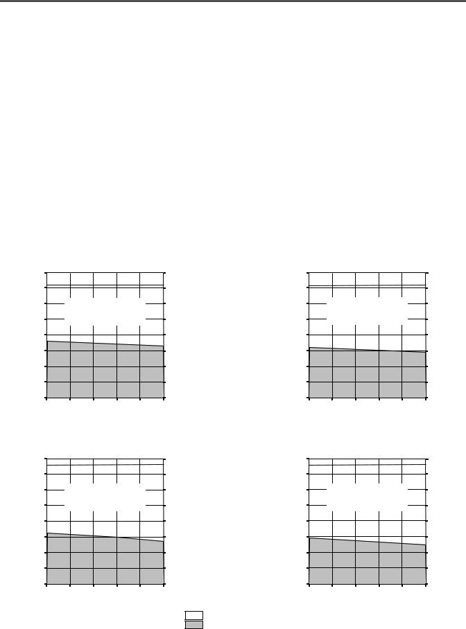
Kinetix 3 (200V-class) Drives/TLY-AxxxP-B (absolute high-resolution) Motor Curves |
|
|
|
|
||||||||||||
|
|
2071-AP1 and TLY-A120P-B |
|
|
|
|
|
2071-AP1 and TLY-A120P-B (Brake) |
|
|
||||||
Torque |
0.400 |
|
|
|
|
3.54 |
Torque |
Torque |
0.400 |
|
|
|
|
|
3.54 |
Torque |
(N•m) |
0.350 |
|
|
|
|
3.10 |
(lb•in) |
(N•m) |
0.350 |
|
|
|
|
|
3.10 |
(lb•in) |
|
0.300 |
Intermittent curve represents |
|
2.65 |
|
|
0.300 |
|
Intermittent curve represents |
|
2.65 |
|
||||
|
0.250 |
|
single-phase input. |
|
2.21 |
|
|
0.250 |
|
|
single-phase input. |
|
2.21 |
|
||
|
|
|
|
|
|
|
|
|
|
|
|
|
||||
|
0.200 |
|
|
|
|
1.77 |
|
|
0.200 |
|
|
|
|
|
1.77 |
|
|
0.150 |
|
|
|
|
1.33 |
|
|
0.150 |
|
|
|
|
|
1.33 |
|
|
0.100 |
|
|
|
|
0.88 |
|
|
0.100 |
|
|
|
|
|
0.88 |
|
|
0.050 |
|
|
|
|
0.44 |
|
|
0.050 |
|
|
|
|
|
0.44 |
|
|
0 |
|
|
|
|
0 |
|
|
0 |
|
|
|
|
|
0 |
|
|
0 |
1000 |
2000 |
3000 |
4000 |
5000 |
|
|
|
0 |
1000 |
2000 |
3000 |
4000 |
5000 |
|
|
|
|
Speed (rpm) |
|
|
|
|
|
|
|
Speed (rpm) |
|
|
|
||
|
|
2071-AP1 and TLY-A130P-B |
|
|
|
|
|
2071-AP1 and TLY-A130P-B (Brake) |
|
|
||||||
Torque |
0.800 |
|
|
|
|
7.08 |
Torque |
Torque |
0.800 |
|
|
|
|
|
7.08 |
Torque |
(N•m) |
0.700 |
|
|
|
|
6.19 |
(lb•in) |
(N•m) |
0.700 |
|
|
|
|
|
6.19 |
(lb•in) |
|
0.600 |
Intermittent curve represents |
|
5.31 |
|
|
0.600 |
|
Intermittent curve represents |
|
5.31 |
|
||||
|
0.500 |
|
single-phase input. |
|
4.42 |
|
|
0.500 |
|
|
single-phase input. |
|
4.42 |
|
||
|
|
|
|
|
|
|
|
|
|
|
|
|
||||
|
0.400 |
|
|
|
|
3.54 |
|
|
0.400 |
|
|
|
|
|
3.54 |
|
|
0.300 |
|
|
|
|
2.65 |
|
|
0.300 |
|
|
|
|
|
2.65 |
|
|
0.200 |
|
|
|
|
1.77 |
|
|
0.200 |
|
|
|
|
|
1.77 |
|
|
0.100 |
|
|
|
|
0.88 |
|
|
0.100 |
|
|
|
|
|
0.88 |
|
|
0 |
|
|
|
|
0 |
|
|
0 |
|
|
|
|
|
0 |
|
|
0 |
1000 |
2000 |
3000 |
4000 |
5000 |
|
|
|
0 |
1000 |
2000 |
3000 |
4000 |
5000 |
|
|
|
|
Speed (rpm) |
|
|
|
|
|
|
|
Speed (rpm) |
|
|
|
||
= Intermittent operating region = Continuous operating region
10 |
Rockwell Automation Publication GMC-RM005B-EN-P - September 2013 |
Kinetix 3 Drive Systems
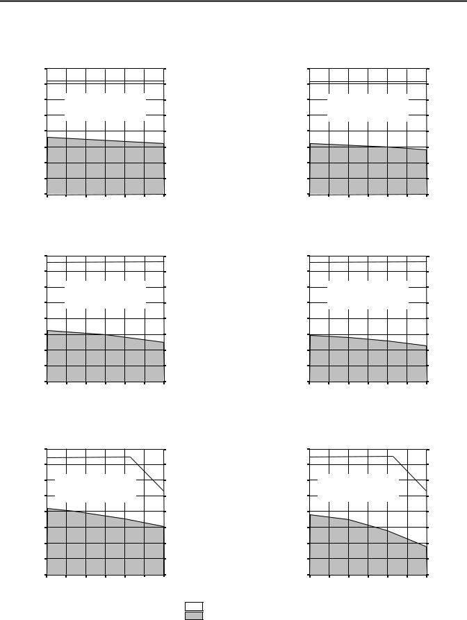
Kinetix 3 (200V-class) Drives/TLY-AxxxP-B (absolute high-resolution) Motor Curves (continued) |
|
|
||||||||||||||
|
|
2071-AP4 and TLY-A220P-B |
|
|
|
|
|
2071-AP4 and TLY-A220P-B (Brake) |
|
|
||||||
Torque |
1.600 |
|
|
|
|
14.1 |
Torque |
Torque |
1.600 |
|
|
|
|
|
14.1 |
Torque |
(N•m) |
1.400 |
|
|
|
|
12.4 |
(lb•in) |
(N•m) |
1.400 |
|
|
|
|
|
12.4 |
(lb•in) |
|
1.200 |
Intermittent curve represents |
|
10.6 |
|
|
1.200 |
|
Intermittent curve represents |
|
10.6 |
|
||||
|
1.000 |
|
single-phase input. |
|
8.85 |
|
|
1.000 |
|
|
single-phase input. |
|
8.85 |
|
||
|
|
|
|
|
|
|
|
|
|
|
|
|
||||
|
0.800 |
|
|
|
|
7.08 |
|
|
0.800 |
|
|
|
|
|
7.08 |
|
|
0.600 |
|
|
|
|
5.31 |
|
|
0.600 |
|
|
|
|
|
5.31 |
|
|
0.400 |
|
|
|
|
3.54 |
|
|
0.400 |
|
|
|
|
|
3.54 |
|
|
0.200 |
|
|
|
|
1.77 |
|
|
0.200 |
|
|
|
|
|
1.77 |
|
|
0 |
|
|
|
|
0 |
|
|
0 |
|
|
|
|
|
0 |
|
|
0 |
1000 |
2000 |
3000 |
4000 |
5000 |
|
|
|
0 |
1000 |
2000 |
3000 |
4000 |
5000 |
|
|
|
|
Speed (rpm) |
|
|
|
|
|
|
|
Speed (rpm) |
|
|
|
||
|
|
2071-AP4 and TLY-A230P-B |
|
|
|
|
|
2071-AP4 and TLY-A230P-B (Brake) |
|
|
||||||
Torque |
4.00 |
|
|
|
|
35.4 |
Torque |
Torque |
4.00 |
|
|
|
|
|
35.4 |
Torque |
(N•m) |
3.50 |
|
|
|
|
31.0 |
(lb•in) |
(N•m) |
3.50 |
|
|
|
|
|
31.0 |
(lb•in) |
|
3.00 |
|
|
|
|
26.5 |
|
|
3.00 |
|
|
|
|
|
26.5 |
|
|
2.50 |
Intermittent curve represents |
|
22.1 |
|
|
2.50 |
|
Intermittent curve represents |
|
22.1 |
|
||||
|
2.00 |
|
single-phase input. |
|
17.7 |
|
|
2.00 |
|
|
single-phase input. |
|
17.7 |
|
||
|
|
|
|
|
|
|
|
|
|
|
|
|
||||
|
1.50 |
|
|
|
|
13.3 |
|
|
1.50 |
|
|
|
|
|
13.3 |
|
|
1.00 |
|
|
|
|
8.85 |
|
|
1.00 |
|
|
|
|
|
8.85 |
|
|
0.50 |
|
|
|
|
4.42 |
|
|
0.50 |
|
|
|
|
|
4.42 |
|
|
0 |
|
|
|
|
0 |
|
|
0 |
|
|
|
|
|
0 |
|
|
0 |
1000 |
2000 |
3000 |
4000 |
5000 |
|
|
|
0 |
1000 |
2000 |
3000 |
4000 |
5000 |
|
|
|
|
Speed (rpm) |
|
|
|
|
|
|
|
Speed (rpm) |
|
|
|
||
=Intermittent operating region
=Continuous operating region
Rockwell Automation Publication GMC-RM005B-EN-P - September 2013 |
11 |
Kinetix 3 Drive Systems
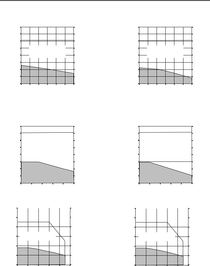
Kinetix 3 (200V-class) Drives/TLY-AxxxT-H (incremental) Motor Curves |
|
|
|
|
|
|
|
|
||||||||||
|
|
2071-AP1 and TLY-A120T-H |
|
|
|
|
|
2071-AP1 and TLY-A120T-H (Brake) |
|
|
||||||||
Torque |
0.400 |
|
|
|
|
|
3.54 |
Torque |
Torque |
0.400 |
|
|
|
|
|
|
3.54 |
Torque |
(N•m) |
0.350 |
|
|
|
|
|
3.10 |
(lb•in) |
(N•m) |
0.350 |
|
|
|
|
|
|
3.10 |
(lb•in) |
|
0.300 |
|
Intermittent curve represents |
|
2.65 |
|
|
0.300 |
|
|
Intermittent curve represents |
|
2.65 |
|
||||
|
0.250 |
|
single-phase input. |
|
2.21 |
|
|
0.250 |
|
|
single-phase input. |
|
2.21 |
|
||||
|
|
|
|
|
|
|
|
|
|
|
|
|
|
|
||||
|
0.200 |
|
|
|
|
|
1.77 |
|
|
0.200 |
|
|
|
|
|
|
1.77 |
|
|
0.150 |
|
|
|
|
|
1.33 |
|
|
0.150 |
|
|
|
|
|
|
1.33 |
|
|
0.100 |
|
|
|
|
|
0.88 |
|
|
0.100 |
|
|
|
|
|
|
0.88 |
|
|
0.050 |
|
|
|
|
|
0.44 |
|
|
0.050 |
|
|
|
|
|
|
0.44 |
|
|
0 |
|
|
|
|
|
0 |
|
|
0 |
|
|
|
|
|
|
0 |
|
|
0 |
1000 |
2000 |
3000 |
4000 |
5000 |
6000 |
|
|
|
0 |
1000 |
2000 |
3000 |
4000 |
5000 |
6000 |
|
|
|
|
Speed (rpm) |
|
|
|
|
|
|
|
Speed (rpm) |
|
|
|
||||
|
|
2071-AP1 and TLY-A130T-H |
|
|
|
|
|
2071-AP1 and TLY-A130T-H (Brake) |
|
|
||||||||
Torque |
0.800 |
|
|
|
|
|
7.08 |
Torque |
Torque |
0.800 |
|
|
|
|
|
|
7.08 |
Torque |
(N•m) |
0.700 |
|
|
|
|
|
6.19 |
(lb•in) |
(N•m) |
0.700 |
|
|
|
|
|
|
6.19 |
(lb•in) |
|
0.600 |
|
Intermittent curve represents |
|
5.31 |
|
|
0.600 |
|
|
Intermittent curve represents |
|
5.31 |
|
||||
|
0.500 |
|
single-phase input. |
|
4.42 |
|
|
0.500 |
|
|
single-phase input. |
|
4.42 |
|
||||
|
|
|
|
|
|
|
|
|
|
|
|
|
|
|
||||
|
0.400 |
|
|
|
|
|
3.54 |
|
|
0.400 |
|
|
|
|
|
|
3.54 |
|
|
0.300 |
|
|
|
|
|
2.65 |
|
|
0.300 |
|
|
|
|
|
|
2.65 |
|
|
0.200 |
|
|
|
|
|
1.77 |
|
|
0.200 |
|
|
|
|
|
|
1.77 |
|
|
0.100 |
|
|
|
|
|
0.88 |
|
|
0.100 |
|
|
|
|
|
|
0.88 |
|
|
0 |
|
|
|
|
|
0 |
|
|
0 |
|
|
|
|
|
|
0 |
|
|
0 |
1000 |
2000 |
3000 |
4000 |
5000 |
6000 |
|
|
|
0 |
1000 |
2000 |
3000 |
4000 |
5000 |
6000 |
|
|
|
|
Speed (rpm) |
|
|
|
|
|
|
|
Speed (rpm) |
|
|
|
||||
|
|
2071-AP4 and TLY-A220T-H |
|
|
|
|
|
2071-AP4 and TLY-A220T-H (Brake) |
|
|
||||||||
Torque |
1.600 |
|
|
|
|
|
14.1 |
Torque |
Torque |
1.600 |
|
|
|
|
|
|
14.1 |
Torque |
(N•m) |
1.400 |
|
|
|
|
|
12.4 |
(lb•in) |
(N•m) |
1.400 |
|
|
|
|
|
|
12.4 |
(lb•in) |
|
1.200 |
Intermittent curve represents |
|
10.6 |
|
|
1.200 |
|
Intermittent curve represents |
|
10.6 |
|
||||||
|
|
|
|
|
|
|
|
|
|
|
||||||||
|
1.000 |
|
single-phase input. |
|
|
8.85 |
|
|
1.000 |
|
|
single-phase input. |
|
|
8.85 |
|
||
|
|
|
|
|
|
|
|
|
|
|
|
|
|
|
||||
|
0.800 |
|
|
|
|
|
7.08 |
|
|
0.800 |
|
|
|
|
|
|
7.08 |
|
|
0.600 |
|
|
|
|
|
5.31 |
|
|
0.600 |
|
|
|
|
|
|
5.31 |
|
|
0.400 |
|
|
|
|
|
3.54 |
|
|
0.400 |
|
|
|
|
|
|
3.54 |
|
|
0.200 |
|
|
|
|
|
1.77 |
|
|
0.200 |
|
|
|
|
|
|
1.77 |
|
|
0 |
|
|
|
|
|
0 |
|
|
0 |
|
|
|
|
|
|
0 |
|
|
0 |
1000 |
2000 |
3000 |
4000 |
5000 |
6000 |
|
|
|
0 |
1000 |
2000 |
3000 |
4000 |
5000 |
6000 |
|
|
|
|
Speed (rpm) |
|
|
|
|
|
|
|
Speed (rpm) |
|
|
|
||||
= Intermittent operating region = Continuous operating region
12 |
Rockwell Automation Publication GMC-RM005B-EN-P - September 2013 |
Kinetix 3 Drive Systems
Kinetix 3 (200V-class) Drives/TLY-AxxxT-H (incremental) Motor Curves (continued) |
|
|
|
|
|
|||||||||||||
|
|
2071-AP4 and TLY-A230T-H |
|
|
|
|
|
2071-AP4 and TLY-A230T-H (Brake) |
|
|
||||||||
Torque |
4.00 |
|
|
|
|
|
35.4 |
Torque |
Torque |
4.00 |
|
|
|
|
|
|
35.4 |
Torque |
(N•m) |
3.50 |
|
|
|
|
|
31.0 |
(lb•in) |
(N•m) |
3.50 |
|
|
|
|
|
|
31.0 |
(lb•in) |
|
3.00 |
|
|
|
|
|
26.5 |
|
|
3.00 |
|
|
|
|
|
|
26.5 |
|
|
2.50 |
|
Intermittent curve represents |
|
22.1 |
|
|
2.50 |
|
|
Intermittent curve represents |
|
22.1 |
|
||||
|
2.00 |
|
single-phase input. |
|
17.7 |
|
|
2.00 |
|
|
single-phase input. |
|
17.7 |
|
||||
|
|
|
|
|
|
|
|
|
|
|
|
|
|
|
||||
|
1.50 |
|
|
|
|
|
13.3 |
|
|
1.50 |
|
|
|
|
|
|
13.3 |
|
|
1.00 |
|
|
|
|
|
8.85 |
|
|
1.00 |
|
|
|
|
|
|
8.85 |
|
|
0.50 |
|
|
|
|
|
4.42 |
|
|
0.50 |
|
|
|
|
|
|
4.42 |
|
|
0 |
|
|
|
|
|
0 |
|
|
0 |
|
|
|
|
|
|
0 |
|
|
0 |
1000 |
2000 |
3000 |
4000 |
5000 |
6000 |
|
|
|
0 |
1000 |
2000 |
3000 |
4000 |
5000 |
6000 |
|
Speed (rpm) |
|
= Intermittent operating region |
Speed (rpm) |
|
= Continuous operating region |
||
|
|
|
Kinetix 3 (200V-class) Drives/TLY-Axxxx-x Motor Curves
|
|
|
|
|
|
2071-AP8 and TLY-A2540P-x |
|
|
|
|
|
|
|
|
|
|
|
|
|
|
2071-AP8 and TLY-A2540P-x (Brake) |
|
|
|
|
|
|
|
|
|||||||||||||||||
Torque |
8.00 |
|
|
|
|
|
|
|
|
|
|
|
70.8 |
Torque |
Torque |
8.00 |
|
|
|
|
|
|
|
|
|
|
|
|
70.8 |
Torque |
||||||||||||||||
|
|
|
|
|
|
|
|
|
|
|
|
|
|
|
|
|
|
|
|
|
|
|
||||||||||||||||||||||||
(N•m) |
7.00 |
|
|
|
|
|
|
|
|
|
|
|
|
61.9 |
(lb•in) |
(N•m) |
7.00 |
|
|
|
|
|
|
|
|
|
|
|
|
|
61.9 |
(lb•in) |
||||||||||||||
|
|
|
|
|
|
|
|
|
|
|
|
|
|
|
|
|
|
|
|
|
|
|
|
|
||||||||||||||||||||||
|
6.00 |
|
|
|
|
|
|
|
|
|
|
|
|
53.1 |
|
|
6.00 |
|
|
|
|
|
|
|
|
|
|
|
|
|
|
53.1 |
|
|||||||||||||
|
|
|
|
Intermittent curve represents |
|
|
|
|
|
|
|
|
|
|
Intermittent curve represents |
|
|
|
|
|
|
|||||||||||||||||||||||||
|
|
|
|
|
|
|
|
|
|
|
|
|
|
|
|
|
|
|
||||||||||||||||||||||||||||
|
|
|
|
|
|
|
|
|
|
|
|
|
|
|
|
|
|
|
|
|
|
|
|
|
|
|
|
|
|
|
|
|
|
|
|
|
||||||||||
|
5.00 |
|
|
three-phase and single-phase inputs. |
|
|
44.2 |
|
|
5.00 |
|
|
|
three-phase and single-phase inputs. |
|
|
44.2 |
|
||||||||||||||||||||||||||||
|
|
|
|
|
|
|
|
|
|
|
|
|
|
|
|
|
|
|
|
|
|
|
|
|
|
|
|
|
||||||||||||||||||
|
4.00 |
|
|
|
|
|
|
|
|
|
|
|
|
|
|
|
35.4 |
|
|
4.00 |
|
|
|
|
|
|
|
|
|
|
|
|
|
|
35.4 |
|
||||||||||
|
|
|
|
|
|
|
|
|
|
|
|
|
|
|
|
|
|
|
|
|
|
|
|
|
|
|
|
|
|
|
|
|||||||||||||||
|
3.00 |
|
|
|
|
|
|
|
|
|
|
|
|
26.5 |
|
|
3.00 |
|
|
|
|
|
|
|
|
|
|
|
|
26.5 |
|
|||||||||||||||
|
|
|
|
|
|
|
|
|
|
|
|
|
|
|
|
|
|
|
|
|
|
|
|
|
|
|
|
|||||||||||||||||||
|
2.00 |
|
|
|
|
|
|
|
|
|
|
|
|
17.7 |
|
|
2.00 |
|
|
|
|
|
|
|
|
|
|
|
|
|
17.7 |
|
||||||||||||||
|
|
|
|
|
|
|
|
|
|
|
|
|
|
|
|
|
|
|
|
|
|
|
|
|
|
|
|
|
||||||||||||||||||
|
1.00 |
|
|
|
|
|
|
|
|
|
|
|
|
|
88.5 |
|
|
1.00 |
|
|
|
|
|
|
|
|
|
|
|
|
|
|
88.5 |
|
||||||||||||
|
|
|
|
|
|
|
|
|
|
|
|
|
|
|
|
|
|
|
|
|
|
|
|
|
|
|
|
|
|
|
||||||||||||||||
|
0 |
|
|
|
|
|
|
|
|
|
|
|
0 |
|
|
0 |
|
|
|
|
|
|
|
|
|
|
|
|
0 |
|
||||||||||||||||
|
|
|
|
|
|
|
|
|
|
|
|
|
|
|
|
|
|
|
|
|
|
|
|
|
|
|
||||||||||||||||||||
|
0 |
1000 |
2000 |
3000 |
4000 |
5000 |
|
|
|
|
|
0 |
1000 |
2000 |
3000 |
4000 |
5000 |
|
||||||||||||||||||||||||||||
|
|
|
|
|
|
|
|
Speed (rpm) |
|
|
|
|
|
|
|
|
|
|
|
|
|
|
|
|
|
|
|
|
Speed (rpm) |
|
|
|
|
|
|
|
|
|
|
|
||||||
|
|
|
|
|
2071-A10 and TLY-A310M-x |
|
|
|
|
|
|
|
|
|
|
|
|
|
|
|
|
|
2071-A10 and TLY-A310M-x (Brake) |
|
|
|
|
|
|
|
|
|||||||||||||||
Torque |
12.0 |
|
|
|
|
|
|
|
|
|
|
|
|
|
106 |
Torque |
Torque |
12.0 |
|
|
|
|
|
|
|
|
|
|
|
|
|
|
106 |
Torque |
||||||||||||
|
|
|
|
|
|
|
|
|
|
|
|
|
|
|
|
|
|
|
|
|
|
|
|
|
|
|||||||||||||||||||||
(N•m) |
10.0 |
|
|
|
|
|
|
|
|
|
|
|
|
|
88.5 |
(lb•in) |
(N•m) |
10.0 |
|
|
|
|
|
|
|
|
|
|
|
|
|
|
88.5 |
(lb•in) |
||||||||||||
|
|
|
|
|
|
|
|
|
|
|
|
|
|
|
|
|
|
|
|
|
|
|
|
|
|
|
|
|
|
|
||||||||||||||||
|
|
|
|
|
|
|
|
|
|
|
|
|
|
|
|
|
|
|
|
|
|
|
|
|
|
|
|
|
||||||||||||||||||
|
|
|
|
|
|
|
|
|
|
|
|
|
|
|
|
|
|
|
|
|
|
|
|
|
|
|
|
|
|
|
||||||||||||||||
8.0 |
70.8 |
8.0 |
70.8 |
6.0 |
Intermittent curve represents |
53.1 |
6.0 |
Intermittent curve represents |
53.1 |
|
three-phase input. |
three-phase input. |
|||||
|
|
|
|
4.0 |
35.4 |
4.0 |
35.4 |
2.0 |
17.7 |
2.0 |
17.7 |
0 |
|
|
|
|
0 |
0 |
|
|
|
|
|
0 |
0 |
1000 |
2000 |
3000 |
4000 |
5000 |
|
0 |
1000 |
2000 |
3000 |
4000 |
5000 |
Speed (rpm) |
|
= Intermittent operating region |
Speed (rpm) |
|
|||
|
|
= Continuous operating region |
|
|
|
|
Rockwell Automation Publication GMC-RM005B-EN-P - September 2013 |
13 |
Loading...