


 Loading...
QUICK START
ARMORSTART® ETHERNET/IP DISTRIBUTED MOTOR CONTROLLER
Getting Started
Introduction
BULLETIN 280E, 281E AND 284E
This guide provides the basic information required to start up an
ArmorStart® EtherNet/Industrial Protocol (IP) Distributed Motor Controller. For detailed information on specific product features or configurations, refer to the ArmorStart EtherNet/IP user manual, Publication 280E-UM001*.
ATTENTION: This guide is intended for qualified service personnel responsible for setting up and servicing these devices. The user must have previous experience with and a basic understanding of electrical terminology, configuration procedures, required equipment, and safety precautions.
The user should have a clear understanding of EtherNet/IP™ network operations, including how slave devices operate on a network and communicate with other devices and the controller. Also, the user should be familiar with and have access to RSLogix 5000™ revision 17.01 or later. This programming software package is referred to often in this manual.
2 ArmorStart EtherNet/IP Distributed Motor Controller Getting Started
General Precautions
Precautions for Bulletin 280E/281E Applications
Precautions for Bulletin 284E Applications
In addition to the precautions listed throughout this manual, the following statements, which are general to the system, must be read and understood.
ATTENTION: The controller contains ESD (electrostatic discharge) sensitive parts and assemblies. Static control precautions are required when installing, testing, servicing, or repairing the assembly. Component damage may result if ESD control procedures are not followed. If you are not familiar with static control procedures, refer to Publication 8000-4.5.2, Guarding against Electrostatic Discharge, or any other applicable ESD protection handbooks.
ATTENTION: An incorrectly applied or installed controller can damage components or reduce product life. Wiring or application errors, such as undersizing the motor, incorrect or inadequate AC supply, or excessive ambient temperatures, may result in malfunction of the system.
ATTENTION: Only personnel familiar with the controller and associated machinery should plan or implement the installation, startup, and subsequent maintenance of the system. Failure to do this may result in personal injury and/or equipment damage.
ATTENTION: To prevent electrical shock, open disconnect switch prior to connecting and disconnecting cables. Risk of shock – environment rating may not be maintained with open receptacles.
ATTENTION: The drive contains high voltage capacitors which take time to discharge after removal of mains supply. Before working on drive, ensure isolation of mains supply from line inputs (R, S, T [L1, L2, L3]). Wait three minutes for capacitors to discharge to safe voltage levels. Failure to do so may result in personal injury or death. Darkened display light-emitting diode (LED)s are not an indication that capacitors have discharged to safe voltage levels. Risk of shock – environment rating may not be maintained with open receptacles.
Publication 280E-QS001B-EN-P – February 2011

ArmorStart EtherNet/IP Distributed Motor Controller Getting Started |
3 |
|
|
ArmorStart EtherNet/IP
Features
ATTENTION: Only qualified personnel familiar with adjustable frequency AC drives and associated machinery should plan or implement the installation, startup, and subsequent maintenance of the system. Failure to do this may result in personal injury and/or equipment damage.
Figure 1 – Bulletin 280E/281E ArmorStart with EtherNet/IP™
Communication Protocol
Local Disconnect |
LED Status |
Indication and Reset |
|
IP Address Notation Area |
Control Module |
|
|
2 Outputs (Micro/M12) |
|
4 Inputs (Micro/M12) |
Hand-Off-Auto Keypad |
|
|
IP Address Switches |
|
Ethernet Ports (DLR) |
Motor Connection |
|
|
Base Module |
|
Ground Terminal |
|
Figure 2 – Bulletin 284E ArmorStart with EtherNet/IP™ Communication Protocol
|
LED Status |
Local Disconnect |
Indication and Reset |
|
|
|
Control Module |
IP Address Notation Area |
|
2 Outputs (Micro/M12) |
Hand-Off-Auto Keypad |
|
|
4 Inputs (Micro/M12) |
|
IP Address Switches |
Source Brake Connection |
|
|
Ethernet Ports (DLR) |
Motor Connection |
|
|
Base Module |
|
Ground Terminal |
Dynamic Brake Connection |
Publication 280E-QS001B-EN-P – February 2011
4 ArmorStart EtherNet/IP Distributed Motor Controller Getting Started
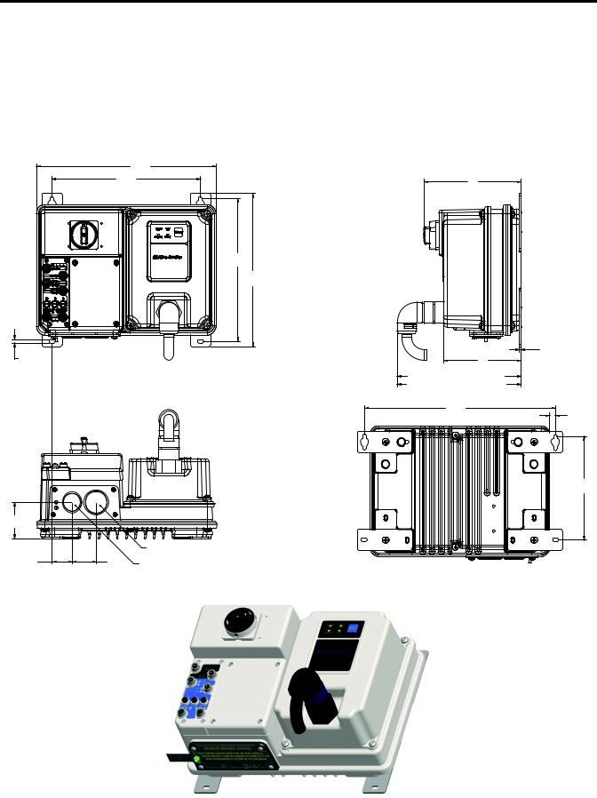
Dimensions
Conduit Gland Entrance
Dimensions are shown in millimeters (inches). Dimensions are not intended to be used for manufacturing purposes. All dimensions are subject to change.
Figure 3 – Dimensions for Bulletin 280E/281E
351 |
[13.82 ] |
290 |
[11.42 ] |
268 [10.55]
287,5 [11.32 ]
6,8 |
] |
|
|
[.27 |
|
|
|
67,9 |
|
|
|
[3] |
|
|
|
|
|
|
1" CONDUIT OPENING |
|
39 |
47 |
0.75" CONDUIT OPENING |
|
[2] |
[1.85] |
|
|
|
189 |
|
[7] |
|
|
3,02 |
150 |
[ .12 ] |
|
|
[6] |
|
MOTOR CONNECTION 185 [7.3] M22 CORDSET |
|
MOTOR CONNECTION 243 [9.57] M35 CORDSET |
|
373 |
|
[14.69 ] |
11 |
|
[ .43] |
195 [7.68]
Publication 280E-QS001B-EN-P – February 2011
ArmorStart EtherNet/IP Distributed Motor Controller Getting Started |
5 |
|
|
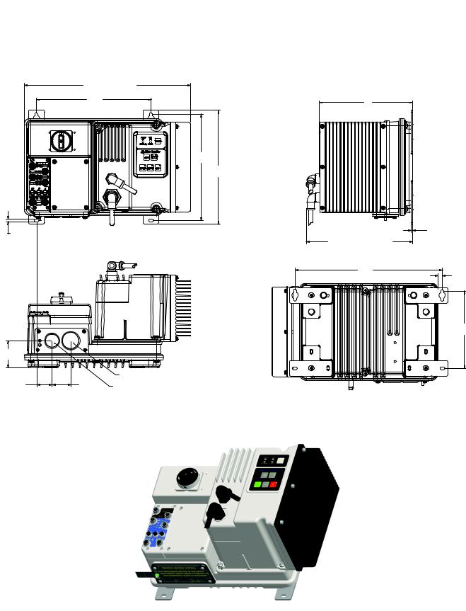
Conduit Gland Entrance
Figure 4 – Dimensions for Bulletin 284E
2HP or less 420.38 [16.55] |
3HP or greater 444.38 [17.50] |
290 |
[11.42] |
268 [10.55]
236 |
[9] |
287,5 [11.32 ]
6,8 |
|
|
3,02 |
|
|
[.12] |
|
[.27] |
|
|
|
|
MOTOR CONNECTION 266.9 [10.51] |
|
|
|
|
|
|
|
|
373 |
|
|
|
[14.69] |
11 |
|
|
|
[.43] |
|
|
|
195 |
|
|
|
[7.68] |
67,9 |
|
|
|
[3] |
|
|
|
|
|
1" CONDUIT OPENING |
|
39 |
47 |
0.75" CONDUIT OPENING |
|
[2] |
[1.85] |
|
|
|
|
Publication 280E-QS001B-EN-P – February 2011
6 ArmorStart EtherNet/IP Distributed Motor Controller Getting Started
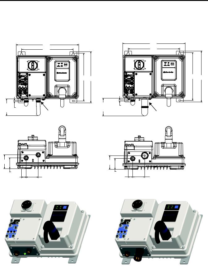
ArmorConnect® Gland
Connectivity
Figure 5 – Dimensions for Bulletin 280E/281E
|
3 Hp and less @ 480V AC |
|
|
10 Hp @ 480V AC |
|
|
351 |
|
|
351 |
|
|
|
|
[13.82] |
|
|
|
[13.82] |
|
|
|
|
|
|
|
290 |
|
|
|
290 |
|
|
|
|
|
[11.42] |
|
|
[11.42] |
|
|
268 |
287,5 |
|
268 |
287,5 |
|
|
[10.55 ] |
|||
|
[10.55] |
[11.32 ] |
|
|
[11.32] |
203.2 |
6,8 |
|
203.2 |
6,8 |
|
[8] |
|
[8] |
[.27] |
|
|
CABLE |
[.27] |
|
CABLE |
|
|
KEEP OUT |
10 Amp Short Circuit |
|
KEEP OUT |
25 Amp Short Circuit |
|
|
|
|
|
||
|
Protection (M22) |
|
|
Protection (M35) |
|
77,6 |
|
[3] |
|
60,6 |
|
[2] |
|
25,5 |
68 |
[1] |
[2.68] |
77,6 |
|
[3] |
|
60,6 |
|
[2] |
|
25,5 |
68 |
[1] |
[2.68] |
Publication 280E-QS001B-EN-P – February 2011

ArmorStart EtherNet/IP Distributed Motor Controller Getting Started |
7 |
|
|
ArmorConnect Gland
Connectivity
Figure 6 – Dimensions for Bulletin 284E
2 Hp or less at 480V |
3 Hp or greater at 480V |
|
|
419,53 |
|
|
444,38 |
|
|
290 |
[16.52] |
|
290 |
[17.50] |
|
|
|
|
30,4 |
|
||
|
[11.42] |
|
|
|
||
|
|
|
[11.42] |
[1] |
|
|
|
|
|
|
|
||
|
|
268 |
287,5 |
|
268 |
287,5 |
|
|
|
[10.55] |
[11.32 ] |
||
|
|
[10.55] |
[11.32] |
|
|
|
6,8 |
10 Amp Short Circuit |
|
6,8 |
|
|
|
[.27] |
|
[.27] |
25 Amp Short Circuit |
|
||
|
|
|
|
|||
|
Protection (M22) |
|
|
Protection (M35) |
|
|
77,6 |
|
[3] |
|
60,6 |
|
[2] |
|
25,5 |
68 |
[1] |
[2.68] |
77,6 |
|
[3] |
|
60,6 |
|
[2] |
|
25,5 |
68 |
[1] |
[2.68] |
Publication 280E-QS001B-EN-P – February 2011
8 ArmorStart EtherNet/IP Distributed Motor Controller Getting Started
Control and Power
Connections
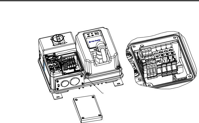
Figure 7 – ArmorStart EtherNet/IP Power and Control Terminals
See Detail A |
Detail A |
Table 1 - Power, Control and Ground Terminal Designations
Terminal Designations |
No. of Poles |
Description |
|
|
|
A1 (+) |
2 |
Control Power Input |
|
|
|
A2 (–) |
2 |
Control Power Common |
|
|
|
A3 (+) |
2 |
Unswitched 24V Control |
|
|
|
PE |
2 |
Ground |
|
|
|
1/L1 |
2 |
Line Power Phase A |
|
|
|
3/L3 |
2 |
Line Power Phase B |
|
|
|
5/L5 |
2 |
Line Power Phase C |
|
|
|
Publication 280E-QS001B-EN-P – February 2011

ArmorStart EtherNet/IP Distributed Motor Controller Getting Started |
9 |
|
|
Recommended Cord Grips
Figure 8 – Cord grips for ArmorStart Devices with 10 A Short Circuit Protection Rating
3/4 in. Lock Nut 
Thomas & Betts Cord Grip Cat. No. 2931NM
3/4 in. Stain Relief Cord Connector Cable Range: 0.31…0.56 in.
Used with Control Power Media Cordset - Example:
Cat. No. 889N-M65GF-M2
1 in. Lock Nut
Thomas & Betts Cord Grip Cat. No. 2940NM
1 in. Stain Relief Cord Connector Cable Range: 0.31…0.56 in. Used with Three-Phase Power Media Cordset - Example:
Cat. No. 280-PWR22G-M1
Figure 9 – Cord grips for ArmorStart Devices with 25 A Short Circuit Protection Rating
3/4 in. Lock Nut
Thomas & Betts Cord Grip Cat. No. 2931NM
3/4 in. Stain Relief Cord Connector
Cable Range: 0.31…0.56 in. Used with Control Power Media
Cordset - Example:
Cat. No. 889N-M65GF-M2
1 in. Lock Nut
Thomas & Betts Cord Grip Cat. No. 2942NM
1 in. Stain Relief Cord Connector  Cable Range: 0.70…0.95 in.
Used with Three-Phase Power Media Cordset - Example:
Cat. No. 280-PWR35G-M1
ArmorConnect Connections
Figure 10 – ArmorConnect Receptacles
10 A Short Circuit Protection Rating |
25 A Short Circuit Protection Rating |
Control Power Receptacle |
Control Power Receptacle |
|
|
Three-Phase Power Receptacle |
Three-Phase Power Receptacle |
Publication 280E-QS001B-EN-P – February 2011
10 ArmorStart EtherNet/IP Distributed Motor Controller Getting Started
Factory installed ArmorConnect gland plate connections
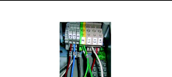
Figure 11 – ArmorConnect Connections
Control Power Wiring
Table 2 - ArmorConnect Gland Plate Conductor Color Code
Terminal Designations |
Description |
Color Code |
|
|
|
A1 (+) |
Control Power Input |
Blue |
|
|
|
A2 (–) |
Control Power Common |
Black |
|
|
|
A3 (+) |
Unswitched Control Power |
Red |
|
|
|
PE |
Ground |
Green/Yellow |
|
|
|
1/L1 |
Line Power – Phase A |
Black |
|
|
|
2/L2 |
Line Power – Phase B |
White |
|
|
|
3/L3 |
Line Power – Phase C |
Red |
|
|
|
ArmorStart EtherNet/IP utilizes 24V DC control power for communications and I/O. The control power terminal connections are labeled A1,A2, and A3. Switched power will supply the outputs. Unswitched power will supply logic power and sensor inputs. The diagram below provides the user an example of the internal and external connections for proper operation.
Publication 280E-QS001B-EN-P – February 2011
ArmorStart EtherNet/IP Distributed Motor Controller Getting Started |
11 |
|
|
Figure 12 – Control Power Wiring Example
24V DC Control Power
•Rated Operation Voltage
– 24V DC (–15%, +10%)
•A1 = Switched +V
•A2 = Common for both switched and unswitched (–V)
•A3 = Unswitched +V
Group Motor Installations for USA and Canada Markets
The ArmorStart Distributed Motor controllers are listed for use with each other in group installations per NFPA 79, Electrical Standard for Industrial Machinery. When applied according to the group motor installation requirements, two or more motors, of any rating or controller type, are permitted on a single branch circuit. Group Motor Installation has been successfully used for many years in the USA and Canada.
Wiring and Workmanship Guidelines
In addition to conduit and seal-tite raceway, it is acceptable to utilize cable that is dual rated Tray Cable, Type TC-ER and Cord, STOOW, for power and control wiring on ArmorStart installations. In the USA and Canada installations, the following guidance is outlined by the NEC and NFPA 79.
In industrial establishments where the conditions of maintenance and supervision ensure that only qualified persons service the installation, and where the exposed cable is continuously supported and protected against physical damage using mechanical protection, such as struts, angles, or channels, Type TC tray cable that complies with the crush and impact requirements of Type MC (Metal Clad) cable and is identified for such use with the marking Type TC-ER (Exposed Run)* shall be permitted between a cable tray and the utilization
Publication 280E-QS001B-EN-P – February 2011

12 ArmorStart EtherNet/IP Distributed Motor Controller Getting Started
equipment or device as open wiring. The cable shall be secured at intervals not exceeding 1.8 m (6 ft) and installed in a “good workman-like” manner. Equipment grounding for the utilization equipment shall be provided by an equipment grounding conductor within the cable.
*Historically cable meeting these crush and impact requirements were designated and marked “Open Wiring”. Cable so marked is equivalent to the present Type TC-ER and can be used.
While the ArmorStart is intended for installation in factory floor environments of industrial establishments, the following must be taken into consideration when locating the ArmorStart in the application: Cables, including those for control voltage including 24V DC and communications, are not to be exposed to an operator or building traffic on a continuous basis. Location of the ArmorStart to minimize exposure to continual traffic is recommended. If location to minimize traffic flow is unavoidable, other barriers to minimize inadvertent exposure to the cabling should be considered. Routing cables should be done in such a manner to minimize inadvertent exposure and/or damage.
Additionally, if conduit or other raceways are not used, it is recommended that strain relief fittings be utilized when installing the cables for the control and power wiring through the conduit openings.
The working space around the ArmorStart may be minimized as the ArmorStart does not require examination, adjustment, servicing or maintenance while energized. In lieu of this service, the ArmorStart is meant to be unplugged and replaced after proper lockout/tag-out procedures have been employed.
The Hand-Off-Auto (HOA) is a factory installed option that the user may select. The HOA keypad may require the ArmorStart to be selected and installed as follows if the application requires frequent use of the hand operated interface by the equipment operator:
1.They are not less than 0.6 m (2 ft) above the servicing level and are within easy reach of the normal working position of the operator.
2.The operator is not placed in a hazardous situation when operating them.
3.The possibility of inadvertent operation is minimized.
If the operated interface is used in industrial establishments where the conditions of maintenance and supervision ensure that only qualified persons operate and service the ArmorStart's operator interface, and the installation is located so that inadvertent operation is minimized then other installation locations with acceptable access can be provided.
Publication 280E-QS001B-EN-P – February 2011
ArmorStart EtherNet/IP Distributed Motor Controller Getting Started |
13 |
|
|
ArmorStart Receptacle Pin
Outs
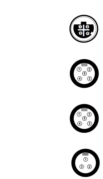
Figure 13 – Receptacle Connections for EtherNet/IP (M12)
Pin 1: Tx+
Pin 2: Rx+
Pin 3: Tx–
Pin 4: Rx–
Figure 14 – Receptacle Connections for Input (M12)
Pin 1: +24V (A3 or DNET)
Pin 2: Input 0
Pin 3: Common
Pin 4: Input 1
Pin 5: NC (no connection)
Figure 15 – Receptacle Connections for Output, EtherNet/IP Version (M12)
Pin 1: NC (no connection)
Pin 2: NC (no connection)
Pin 3: Common
Pin 4: Output +24V DC (A1)
Pin 5: NC (no connection)
Figure 16 – Receptacle Connections for Dynamic Brake (M22) – Bulletin 284E only
Pin 1: GND (green/yellow)
Pin 2: BR+ (black)
Pin 3: BR- (white)
Publication 280E-QS001B-EN-P – February 2011
14 ArmorStart EtherNet/IP Distributed Motor Controller Getting Started
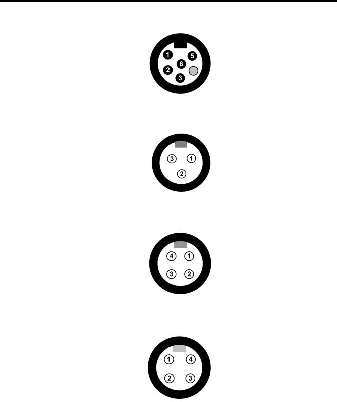
Figure 17 – Receptacle Connections for Incoming Control Power – 24V DC Only
Pin 1: +24V DC unswitched (A3) (red)
Pin 2: Common (A2) (black)
Pin 3: PE (green)
Pin 4: Not used (blank)
Pin 5: +24V DC switched (A1) (blue)
Pin 6: Not used (white)
Figure 18 – Receptacle Connections for Source or Control Brake – Bulletin 284E only
Pin 1: L1 (black)
Pin 2: GND (green/yellow)
Pin 3: L2 (white)
Figure 19 – Receptacle Connections for Motor Connector (M22) – Bulletin 280E/ 281E: 3 Hp or less and Bulletin 284E: 5 Hp or less
Pin 1: T1 (black)
Pin 2: T2 (white)
Pin 3: T3 (red)
Pin 4: Ground (green/yellow)
Figure 20 – Receptacle Connections for Motor Connector – 10 Hp or greater (M35) – Bulletin 280E/281E only
Pin 1: T1 (black)
Pin 2: Ground (green/yellow)
Pin 3: T3 (red)
Pin 4: T2 (white)
Publication 280E-QS001B-EN-P – February 2011
Loading...