


 Loading...
User Manual
ArmorStart® LT Distributed Motor Controller
Catalog Numbers 290E, 291E, 294E
Important User Information
Because of the variety of uses for the products described in this publication, those responsible for the application and use of this control equipment must satisfy themselves that all necessary steps have been taken to assure that each application and use meets all performance and safety requirements, including any applicable laws, regulations, codes and standards.
The illustrations, charts, sample programs and layout examples shown in this guide are intended solely for purposes of example. Since there are many variables and requirements associated with any particular installation, Rockwell Automation does not assume responsibility or liability (to include intellectual property liability) for actual use based upon the examples shown in this publication.
Solid-state equipment has operational characteristics differing from those of electromechanical equipment. Safety Guidelines for the Application, Installation and Maintenance of Solid State Controls (Publication SGI-1.1 available from your local Rockwell Automation sales office or online at http://www.rockwellautomation.com/literature/) describes some important differences between solid-state equipment and hard-wired electromechanical devices. Because of this difference, and also because of the wide variety of uses for solid-state equipment, all persons responsible for applying this equipment must satisfy themselves that each intended application of this equipment is acceptable.
In no event will Rockwell Automation, Inc. be responsible or liable for indirect or consequential damages resulting from the use or application of this equipment.
The examples and diagrams in this manual are included solely for illustrative purposes. Because of the many variables and requirements associated with any particular installation, Rockwell Automation, Inc. cannot assume responsibility or liability for actual use based on the examples and diagrams.
No patent liability is assumed by Rockwell Automation, Inc. with respect to use of information, circuits, equipment, or software described in this manual.
Reproduction of the contents of this manual, in whole or in part, without written permission of Rockwell Automation, Inc., is prohibited.
Throughout this manual, when necessary, we use notes to make you aware of safety considerations.
WARNING: Identifies information about practices or circumstances that can cause an explosion in a hazardous environment, which may lead to personal injury or death, property damage, or economic loss.
ATTENTION: Identifies information about practices or circumstances that can lead to personal injury or death, property damage, or economic loss. Attentions help you identify a hazard, avoid a hazard, and recognize the consequence.
SHOCK HAZARD: Labels may be on or inside the equipment, for example, a drive or motor, to alert people that dangerous voltage may be present.
BURN HAZARD: Labels may be on or inside the equipment, for example, a drive or motor, to alert people that surfaces may reach dangerous temperatures.
IMPORTANT Identifies information that is critical for successful application and understanding of the product.
General Precautions
In addition to the precautions listed throughout this manual, the following statements, which are general to the system, must be read and understood.
ATTENTION: This manual is intended for qualified service personnel responsible for setting up and servicing these devices. The user must have previous experience with and a basic understanding of electrical terminology, configuration procedures, required equipment, and safety precautions.
WARNING: The National Electrical Code (NEC), NFPA79, and any other governing regional or local code will overrule the information in this manual. Rockwell Automation cannot assume responsibility for the compliance or proper installation of the ArmorStart LT or associated equipment. A hazard of personal injury and/or equipment damage exists if codes are ignored during installation.
ATTENTION: The controller contains ESD (electrostatic discharge) sensitive parts and assemblies. Static control precautions are required when installing, testing, servicing, or repairing the assembly. Component damage may result if ESD control procedures are not followed. If you are not familiar with static control procedures, refer to Publication 8000-4.5.2, Guarding against Electrostatic Discharge, or any other applicable ESD protection handbooks.
ATTENTION: Only personnel familiar with the controller and associated machinery should plan or implement the installation, startup, and subsequent maintenance of the system. Failure to do this may result in personal injury and/or equipment damage.
Precautions for Bulletin 294E Applications
ATTENTION: Only qualified personnel familiar with adjustable frequency AC drives and associated machinery should plan or implement the installation, startup, and subsequent maintenance of the system. Failure to do this may result in personal injury and/or equipment damage.
Rockwell Automation Publication 290E-UM001B-EN-P - June 2012 |
3 |

Software Requirements
The table lists the versions of software that are required.
Software |
Version |
|
|
RSLinx Classic |
2.56 or later |
|
|
RSLogix 5000 |
17.01 or later |
|
Download the most current version of the Add-On Profile from |
|
http://www.rockwellautomation.com/support/downloads.html. |
BOOTP/DHCP |
Version 2.3 or later |
|
|
Additional Resources
These documents and websites contain additional information concerning related Rockwell Automation products.
You can view or download publications at http:/www.rockwellautomation.com/literature/. To order paper copies of technical documentation, contact your local Allen-Bradley distributor or Rockwell Automation sales representative.
Table 1 - Rockwell Automation Industrial Network Resources
Resource |
Description |
|
|
http://ab.rockwellautomation.com/Networks-and-Communications |
Rockwell Automation networks and communication website |
|
|
http://ab.rockwellautomation.com/Networks-and-Communications/Ethernet-IP- |
Rockwell Automation EtherNet/IP website |
Network |
|
|
|
http://www.rockwellautomation.com/services/networks/ |
Rockwell Automation network and security services websites |
http://www.rockwellautomation.com/services/security/ |
|
|
|
http://www.ab.com/networks/architectures.html |
Education series webcasts for IT and controls professionals |
|
|
EtherNet/IP Embedded Switch Technology Application Guide, Publication ENET-AP005 |
Describes how to install, configure, and maintain linear and device-level Ring (DLR) |
|
networks using Rockwell Automation EtherNet/IP devices with embedded switch |
|
technology. |
|
|
EtherNet/IP Network Configuration User Manual, Publication ENET-UM001 |
Describes how to configure and use EtherNet/IP communication modules with a |
|
Logix5000 controller and communicate with various devices on the Ethernet network. |
|
|
EtherNet Design Consideration, Publication ENET-RM002A-EN-P |
Provides details on ethernet design and infrastructure. |
|
|
EtherNet/IP Modules in Logix5000 Control Systems User Manual, Publication ENET-UM001 |
Provides details about how to configure your module. |
|
|
EtherNet/IP Embedded Switch Technology Application Guide, Publication ENET-AP005 |
Provides information about using products with embedded switch technology to |
|
construct networks with linear and ring topologies. |
|
|
EtherNet/IP Industrial Protocol White Paper, Publication ENET-WP001 |
Describes how to implement services and data objects on a TCP/UDP/IP based Ethernet |
|
network. |
|
|
Industrial Automation Wiring and Grounding Guidelines, Publication 1770-4.1 |
Provides general guidelines for installing a Rockwell Automation industrial system. |
|
|
Wiring and Grounding Guidelines, (PWM) AC Drives, Publication DRIVES-IN001 |
Describes wiring and grounding guidelines for Pulse Width Modulated (PWM) AC Drives |
|
|
Product Certifications website, |
Provides declarations of conformity, certificates, and other certification details. |
http://www.rockwellautomation.com/products/certification/ |
|
|
|
4 |
Rockwell Automation Publication 290E-UM001B-EN-P - June 2012 |

Table 2 - ODVA Resources
Resource |
Description |
|
|
http://www.odva.org/ |
Open DeviceNet Vendors Association (ODVA) website |
|
|
http://www.odva.org/default.aspx?tabid=54 |
The CIP Advantage website |
|
• CIP features and benefits |
|
• How to get started |
|
|
Ethernet Media Planning and Installation Manual, ODVA publication |
Describes the required media components and how to plan for, install, verify, |
http://www.odva.org/Portals/0/Library/Publications_Numbered/ |
troubleshoot, and certify an Ethernet network. |
PUB00148R0_EtherNetIP_Media_Planning_and_Installation_Manual.pdf |
|
|
|
Network Infrastructure for EtherNet/IP: Introduction and Considerations, ODVA publication |
Provides an overview of the technologies used in EtherNet/IP networks and provides |
http://www.odva.org/Portals/0/Library/Publications_Numbered/ |
guidelines for deploying infrastructure devices in EtherNet/IP networks. |
PUB00035R0_Infrastructure_Guide.pdf |
|
|
|
Table 3 - Product Selection Resources
Resource |
Description |
|
|
Industrial Controls catalog website, |
Industrial Controls catalog website |
http://www.ab.com/catalogs/ |
|
|
|
ArmorStart LT Distributed Motor Controller Selection Guide, Publication 290-SG001 |
Product selection guide |
|
|
Table 4 - Cisco and Rockwell Automation Alliance Resources
Resource |
Description |
|
|
http://www.ab.com/networks/architectures.html |
Rockwell Automation and Cisco Systems reference architecture website |
|
|
Converged Plantwide Ethernet (CPwE) Design and Implementation Guide, Publication |
Represents a collaborative development effort from Rockwell Automation and Cisco |
ENET-TD001 |
Systems. The design guide is built on, and adds to, design guidelines from the Cisco |
|
Ethernet-to-the-Factory (EttF) solution and the Rockwell Automation Integrated |
|
Architecture. The design guide focuses on the manufacturing industry. |
|
|
Rockwell Automation Support
Rockwell Automation provides technical information on the Web to assist you in using its products. At http://www.rockwellautomation.com/support/, you can find technical manuals, a knowledge base of FAQs, technical and application notes, sample code and links to software service packs, and a MySupport feature that you can customize to make the best use of these tools.
Installation Assistance
If you experience a problem within the first 24 hours of installation, contact Customer Support.
United States or Canada |
1.440.646.3434 |
|
|
Outside United States or |
Use the Worldwide Locator at http://www.rockwellautomation.com/support/ |
Canada |
americas/phone_en.html, or contact your local Rockwell Automation representative. |
|
|
Rockwell Automation Publication 290E-UM001B-EN-P - June 2012 |
5 |

New Product Satisfaction Return
Rockwell Automation tests all of its products to ensure that they are fully operational when shipped from the manufacturing facility. However, if your product is not functioning and needs to be returned, follow these procedures.
United States |
Contact your distributor. You must provide a Customer Support case number (call the |
|
phone number above to obtain one) to your distributor to complete the return process. |
|
|
Outside United States |
Please contact your local Rockwell Automation representative for the return |
|
procedure. |
|
|
6 |
Rockwell Automation Publication 290E-UM001B-EN-P - June 2012 |

Summary of Changes
New and Updated
Information
This table contains the changes made to this revision.
Topic |
Page |
|
|
Added source brake and IPS specifications |
Various |
|
|
|
|
|
|
|
|
|
|
|
|
|
|
|
|
|
|
|
|
Rockwell Automation Publication 290E-UM001B-EN-P - June 2012 |
7 |

Summary of Changes
Notes:
8 |
Rockwell Automation Publication 290E-UM001B-EN-P - June 2012 |

Preface
European Communities (EC)
Directive Compliance
Low Voltage and EMC
Directives
If this product has the CE mark it is approved for installation within the European Union and European Economic Area (EEA). It has been designed and tested to meet the following directives.
This product is tested to meet the European Union (EU) Council 2006/95/EC Low Voltage Directive and the EU Council 2004/108/EC Electromagnetic Compatibility (EMC) Directive by applying the following standard(s):
•Bulletin 290E_/291E_: EN 60947-4-1 — Low-voltage switchgear and controlgear — Part 4-1: Contactors and motor-starters — Electromechanical contactors and motor-starters.
•Bulletin 294E_: EN 61800-3 — Adjustable speed electronic power drive systems — Part 3: EMC product standard including specific test methods EN 61800-5-1:2003 — Adjustable speed electrical power drive systems — Part 5-1: Safety requirements — Electrical, thermal and energy.
This product is intended for use in an industrial environment.
Rockwell Automation Publication 290E-UM001B-EN-P - June 2012 |
9 |

Preface
Introduction
The ArmorStart LT is an integrated, pre-engineered, motor starting solution designed for use in material handling applications. ArmorStart LT is the latest addition to the ArmorStart portfolio. ArmorStart LT is a leader in the market place given its compact size and high performance features in network, I/O, and motor control. This manual will guide you through the features and functionality when installing the product. Thank you for choosing ArmorStart LT for your distributed motor control needs. If you have any questions please refer to the “Support Section” for contact information.
10 |
Rockwell Automation Publication 290E-UM001B-EN-P - June 2012 |
|
Table of Contents |
|
|
Important User Information . . . . . . . . . . . . . . . . . . . . . . . . . . . . . . . . . . . . . . . |
2 |
|
General Precautions . . . . . . . . . . . . . . . . . . . . . . . . . . . . . . . . . . . . . . . . . . . . . . . |
. 3 |
|
Software Requirements . . . . . . . . . . . . . . . . . . . . . . . . . . . . . . . . . . . . . . . . . . . . |
. 4 |
|
Additional Resources . . . . . . . . . . . . . . . . . . . . . . . . . . . . . . . . . . . . . . . . . . . . . . |
. 4 |
|
Rockwell Automation Support . . . . . . . . . . . . . . . . . . . . . . . . . . . . . . . . . . . . . |
. 5 |
|
Installation Assistance . . . . . . . . . . . . . . . . . . . . . . . . . . . . . . . . . . . . . . . . . . . . . |
. 5 |
|
New Product Satisfaction Return . . . . . . . . . . . . . . . . . . . . . . . . . . . . . . . . . . . |
. 6 |
|
Summary of Changes |
|
|
New and Updated Information. . . . . . . . . . . . . . . . . . . . . . . . . . . . . . . . . . . . . |
. 7 |
|
Preface |
|
|
European Communities (EC) Directive Compliance . . . . . . . . . . . . . . . . . |
9 |
|
Low Voltage and EMC Directives . . . . . . . . . . . . . . . . . . . . . . . . . . . . . . . . . . |
9 |
|
Introduction. . . . . . . . . . . . . . . . . . . . . . . . . . . . . . . . . . . . . . . . . . . . . . . . . . . . . . |
10 |
|
Chapter 1 |
|
Product Overview |
Description . . . . . . . . . . . . . . . . . . . . . . . . . . . . . . . . . . . . . . . . . . . . . . . . . . . . . . |
17 |
|
Features . . . . . . . . . . . . . . . . . . . . . . . . . . . . . . . . . . . . . . . . . . . . . . . . . . . . . . . . . |
18 |
|
Feature Description . . . . . . . . . . . . . . . . . . . . . . . . . . . . . . . . . . . . . . . . . . . . . . |
19 |
|
Standard Features Across Product Familly . . . . . . . . . . . . . . . . . . . . . . |
19 |
|
Network Options . . . . . . . . . . . . . . . . . . . . . . . . . . . . . . . . . . . . . . . . . . . . . . . . |
20 |
|
Factory Installed Options . . . . . . . . . . . . . . . . . . . . . . . . . . . . . . . . . . . . . . . . . |
22 |
|
ArmorStart LT Characteristics Bulletin 290E/291E . . . . . . . . . . . . . . . . |
23 |
|
Catalog Number Explanation Bulletin 290E/291E. . . . . . . . . . . . . . . . . . |
24 |
|
ArmorStart LT Characteristics Bulletin 294E . . . . . . . . . . . . . . . . . . . . . . |
25 |
|
Catalog Number Explanation Bulletin 294E. . . . . . . . . . . . . . . . . . . . . . . . . |
26 |
|
Basic Operation . . . . . . . . . . . . . . . . . . . . . . . . . . . . . . . . . . . . . . . . . . . . . . . . . . . |
27 |
|
Group Motor Installations for USA and Canada Markets . . . . . . . . . |
27 |
|
Control Circuit . . . . . . . . . . . . . . . . . . . . . . . . . . . . . . . . . . . . . . . . . . . . . . . |
27 |
|
Motor Circuit. . . . . . . . . . . . . . . . . . . . . . . . . . . . . . . . . . . . . . . . . . . . . . . . . |
29 |
|
Local I/O . . . . . . . . . . . . . . . . . . . . . . . . . . . . . . . . . . . . . . . . . . . . . . . . . . . . . |
29 |
|
Overload Protection . . . . . . . . . . . . . . . . . . . . . . . . . . . . . . . . . . . . . . . . . . . |
30 |
|
Mode of Operation Bulletin 290E/291E . . . . . . . . . . . . . . . . . . . . . . . . . . . . |
30 |
|
Full-Voltage Start. . . . . . . . . . . . . . . . . . . . . . . . . . . . . . . . . . . . . . . . . . . . . . |
30 |
|
Mode of Operation Bulletin 294E . . . . . . . . . . . . . . . . . . . . . . . . . . . . . . . . . . |
31 |
|
Sensorless Vector Performance. . . . . . . . . . . . . . . . . . . . . . . . . . . . . . . . . . |
31 |
|
Status LEDs and Reset. . . . . . . . . . . . . . . . . . . . . . . . . . . . . . . . . . . . . . . . . . . . . |
32 |
|
Electronic Data Sheet (EDS) . . . . . . . . . . . . . . . . . . . . . . . . . . . . . . . . . . . |
33 |
|
Fault Diagnostics. . . . . . . . . . . . . . . . . . . . . . . . . . . . . . . . . . . . . . . . . . . . . . . . . . |
34 |
|
Protection Faults . . . . . . . . . . . . . . . . . . . . . . . . . . . . . . . . . . . . . . . . . . . . . . |
34 |
|
Optional HOA Selector Keypad. . . . . . . . . . . . . . . . . . . . . . . . . . . . . . . . . . . . |
35 |
|
Keypad Local Control . . . . . . . . . . . . . . . . . . . . . . . . . . . . . . . . . . . . . . . . . |
35 |
|
Optional HOA Keypad Configuration (Bulletin 290E/291E only). . . . |
35 |
Rockwell Automation Publication 290E-UM001B-EN-P - June 2012 |
11 |

Table of Contents |
|
|
|
Optional HOA Selector Keypad |
|
|
with Jog Function(Bulletin 294E only). . . . . . . . . . . . . . . . . . . . . . . . . . . . . . |
37 |
|
Keypad Local Control . . . . . . . . . . . . . . . . . . . . . . . . . . . . . . . . . . . . . . . . . |
37 |
|
Keypad and HOA Disable Parameter. . . . . . . . . . . . . . . . . . . . . . . . . . . . |
38 |
|
Source Brake Contactor and Connector (Bulletin 294E only). . . . . . . . . |
38 |
|
Chapter 2 |
|
Installation and Wiring |
Receiving . . . . . . . . . . . . . . . . . . . . . . . . . . . . . . . . . . . . . . . . . . . . . . . . . . . . . . . . . |
39 |
|
Unpacking. . . . . . . . . . . . . . . . . . . . . . . . . . . . . . . . . . . . . . . . . . . . . . . . . . . . . . . . |
39 |
|
Inspecting . . . . . . . . . . . . . . . . . . . . . . . . . . . . . . . . . . . . . . . . . . . . . . . . . . . . . . . . |
39 |
|
Storing . . . . . . . . . . . . . . . . . . . . . . . . . . . . . . . . . . . . . . . . . . . . . . . . . . . . . . . . . . . |
39 |
|
Installation Precautions. . . . . . . . . . . . . . . . . . . . . . . . . . . . . . . . . . . . . . . . . . . . |
40 |
|
Precautions for Bulletin 290E/291E Applications. . . . . . . . . . . . . . . . . . . . |
40 |
|
Precautions for Bulletin 294E Applications. . . . . . . . . . . . . . . . . . . . . . . . . . |
40 |
|
Dimensions. . . . . . . . . . . . . . . . . . . . . . . . . . . . . . . . . . . . . . . . . . . . . . . . . . . . . . . |
40 |
|
Bulletin 290E/291E . . . . . . . . . . . . . . . . . . . . . . . . . . . . . . . . . . . . . . . . . . . |
41 |
|
Bulletin 294E . . . . . . . . . . . . . . . . . . . . . . . . . . . . . . . . . . . . . . . . . . . . . . . . . |
42 |
|
ArmorStart LT Gland Plate Matrix . . . . . . . . . . . . . . . . . . . . . . . . . . . . . |
43 |
|
Connection Locations . . . . . . . . . . . . . . . . . . . . . . . . . . . . . . . . . . . . . . . . . . . . . |
43 |
|
Internal Power, Control, and Ground Locations . . . . . . . . . . . . . . . . . |
43 |
|
Gland Connection. . . . . . . . . . . . . . . . . . . . . . . . . . . . . . . . . . . . . . . . . . . . . |
44 |
|
Wiring Terminal Detail. . . . . . . . . . . . . . . . . . . . . . . . . . . . . . . . . . . . . . . . . . . . |
45 |
|
Branch Circuit Protection . . . . . . . . . . . . . . . . . . . . . . . . . . . . . . . . . . . . . . . . . |
46 |
|
Simple System Design . . . . . . . . . . . . . . . . . . . . . . . . . . . . . . . . . . . . . . . . . . . . . |
47 |
|
ArmorConnect Power . . . . . . . . . . . . . . . . . . . . . . . . . . . . . . . . . . . . . . . . . . . . . |
48 |
|
ArmorConnect Cable Ratings. . . . . . . . . . . . . . . . . . . . . . . . . . . . . . . . . . . . . . |
49 |
|
Branch Circuit Protection Requirements for ArmorConnect |
|
|
Three-Phase Power Media. . . . . . . . . . . . . . . . . . . . . . . . . . . . . . . . . . . . . . |
49 |
|
Electrical Wiring . . . . . . . . . . . . . . . . . . . . . . . . . . . . . . . . . . . . . . . . . . . . . . . . . . |
50 |
|
Group Motor Installations for USA and Canada Markets . . . . . . . . . . . . |
55 |
|
Wiring . . . . . . . . . . . . . . . . . . . . . . . . . . . . . . . . . . . . . . . . . . . . . . . . . . . . . . . . . . . |
55 |
|
Cable Workmanship Guidelines . . . . . . . . . . . . . . . . . . . . . . . . . . . . . . . . |
55 |
|
Service Space . . . . . . . . . . . . . . . . . . . . . . . . . . . . . . . . . . . . . . . . . . . . . . . . . . |
56 |
|
Hand Operation (HOA) Considerations. . . . . . . . . . . . . . . . . . . . . . . . |
56 |
|
General Wiring Considerations . . . . . . . . . . . . . . . . . . . . . . . . . . . . . . . . . . . . |
56 |
|
Grounding. . . . . . . . . . . . . . . . . . . . . . . . . . . . . . . . . . . . . . . . . . . . . . . . . . . . . . . . |
57 |
|
Grounding Safety Grounds . . . . . . . . . . . . . . . . . . . . . . . . . . . . . . . . . . . . . |
57 |
|
Grounding PE or Ground . . . . . . . . . . . . . . . . . . . . . . . . . . . . . . . . . . . . . . |
57 |
|
Grounding Motors . . . . . . . . . . . . . . . . . . . . . . . . . . . . . . . . . . . . . . . . . . . . |
57 |
|
Power Distribution. . . . . . . . . . . . . . . . . . . . . . . . . . . . . . . . . . . . . . . . . . . . . . . . |
58 |
|
Delta/Wye with Grounded Wye Neutral . . . . . . . . . . . . . . . . . . . . . . . . |
58 |
|
AC Line Voltage . . . . . . . . . . . . . . . . . . . . . . . . . . . . . . . . . . . . . . . . . . . . . . . . . . |
58 |
|
Line Reactor . . . . . . . . . . . . . . . . . . . . . . . . . . . . . . . . . . . . . . . . . . . . . . . . . . . . . . |
58 |
|
Bulletin 294E Motor Cable Considerations . . . . . . . . . . . . . . . . . . . . . . . . . |
59 |
|
Unshielded Cable . . . . . . . . . . . . . . . . . . . . . . . . . . . . . . . . . . . . . . . . . . . . . |
59 |
|
Shielded Cable . . . . . . . . . . . . . . . . . . . . . . . . . . . . . . . . . . . . . . . . . . . . . . . . |
60 |
|
Recommended Cable Connectors/Glands . . . . . . . . . . . . . . . . . . . . . . . |
60 |
12 |
Rockwell Automation Publication 290E-UM001B-EN-P - June 2012 |

Table of Contents
Product Commissioning
Bulletin 290E/291E/294E Programmable Parameters
Recommended Cord Grips . . . . . . . . . . . . . . . . . . . . . . . . . . . . . . . . . . . . .61
Shield Terminating Connectors . . . . . . . . . . . . . . . . . . . . . . . . . . . . . . . .61
Electromagnetic Compatibility (EMC) . . . . . . . . . . . . . . . . . . . . . . . . . . . . .62
General Notes (Bulletin 294E only) . . . . . . . . . . . . . . . . . . . . . . . . . . . . .62
Ethernet, DeviceNet, and I/O Connections . . . . . . . . . . . . . . . . . . . . . . . . .63
ArmorConnect Power Media Receptacles . . . . . . . . . . . . . . . . . . . . . . . . . . .64
Optional Locking Clip. . . . . . . . . . . . . . . . . . . . . . . . . . . . . . . . . . . . . . . . . . . . .65
Chapter 3
IP Address . . . . . . . . . . . . . . . . . . . . . . . . . . . . . . . . . . . . . . . . . . . . . . . . . . . . . . . .67 Gateway Address . . . . . . . . . . . . . . . . . . . . . . . . . . . . . . . . . . . . . . . . . . . . . .67
Subnet Mask . . . . . . . . . . . . . . . . . . . . . . . . . . . . . . . . . . . . . . . . . . . . . . . . . .67
Configuring EtherNet/IP Address. . . . . . . . . . . . . . . . . . . . . . . . . . . . . . . . . .68 Manually Configure the Network Address Switches . . . . . . . . . . . . . .68
Static Address Alternative . . . . . . . . . . . . . . . . . . . . . . . . . . . . . . . . . . . . . .69 Using the Rockwell Automation BootP/DHCP Utility . . . . . . . . . . . . . .69 Save the Relation List . . . . . . . . . . . . . . . . . . . . . . . . . . . . . . . . . . . . . . . . . .72
Embedded Web Server . . . . . . . . . . . . . . . . . . . . . . . . . . . . . . . . . . . . . . . . . . . .74
Network Configuration. . . . . . . . . . . . . . . . . . . . . . . . . . . . . . . . . . . . . . . .75 Parameter Configuration. . . . . . . . . . . . . . . . . . . . . . . . . . . . . . . . . . . . . . .76
E-mail Notification Configuration . . . . . . . . . . . . . . . . . . . . . . . . . . . . . .76
How to Add a New Module Using the Add-On Profile. . . . . . . . . . . . . . .78 Electronic Keying. . . . . . . . . . . . . . . . . . . . . . . . . . . . . . . . . . . . . . . . . . . . . .80
Connections . . . . . . . . . . . . . . . . . . . . . . . . . . . . . . . . . . . . . . . . . . . . . . . . . .81
Configured By . . . . . . . . . . . . . . . . . . . . . . . . . . . . . . . . . . . . . . . . . . . . . . . .81 HOA Keypad Option. . . . . . . . . . . . . . . . . . . . . . . . . . . . . . . . . . . . . . . . . .82
Source Brake Electro-Mehanical Brake Option. . . . . . . . . . . . . . . . . . .82
User Configurable I/O. . . . . . . . . . . . . . . . . . . . . . . . . . . . . . . . . . . . . . . . .82 RSLogix 5000 Add-On Profile . . . . . . . . . . . . . . . . . . . . . . . . . . . . . . . . . . . . .83
Auto-Generated Tags . . . . . . . . . . . . . . . . . . . . . . . . . . . . . . . . . . . . . . . . . .85
Chapter 4
Electronic Data Sheet (EDS) . . . . . . . . . . . . . . . . . . . . . . . . . . . . . . . . . . . . . . .99
Basic Setup Parameters . . . . . . . . . . . . . . . . . . . . . . . . . . . . . . . . . . . . . . . . . . . .99
Parameter Groups . . . . . . . . . . . . . . . . . . . . . . . . . . . . . . . . . . . . . . . . . . . . . . . .100
ArmorStart LT EtherNet/IP Parameters . . . . . . . . . . . . . . . . . . . . . . . . . . .102
Introduction. . . . . . . . . . . . . . . . . . . . . . . . . . . . . . . . . . . . . . . . . . . . . . . . . . . . .102
Parameter Programming . . . . . . . . . . . . . . . . . . . . . . . . . . . . . . . . . . . . . . . . . .102
Bulletin 290E/291E . . . . . . . . . . . . . . . . . . . . . . . . . . . . . . . . . . . . . . . . . . . . . .102
Basic Status Group . . . . . . . . . . . . . . . . . . . . . . . . . . . . . . . . . . . . . . . . . . . . . . .102
Trip Status Group . . . . . . . . . . . . . . . . . . . . . . . . . . . . . . . . . . . . . . . . . . . .107
Basic Configuration Group. . . . . . . . . . . . . . . . . . . . . . . . . . . . . . . . . . . .111
Starter Protection Group. . . . . . . . . . . . . . . . . . . . . . . . . . . . . . . . . . . . . .112
User I/O Configuration Group. . . . . . . . . . . . . . . . . . . . . . . . . . . . . . . .115
Miscellaneous Configuration Group . . . . . . . . . . . . . . . . . . . . . . . . . . .119
Advanced Configuration . . . . . . . . . . . . . . . . . . . . . . . . . . . . . . . . . . . . . .121
Rockwell Automation Publication 290E-UM001B-EN-P - June 2012 |
13 |

Table of Contents |
|
|
|
Bulletin 294E . . . . . . . . . . . . . . . . . . . . . . . . . . . . . . . . . . . . . . . . . . . . . . . . . . . . |
124 |
|
Basic Status Group . . . . . . . . . . . . . . . . . . . . . . . . . . . . . . . . . . . . . . . . . . . |
124 |
|
Trip Status Group . . . . . . . . . . . . . . . . . . . . . . . . . . . . . . . . . . . . . . . . . . . . |
129 |
|
Motor and Control Group . . . . . . . . . . . . . . . . . . . . . . . . . . . . . . . . . . . . |
133 |
|
Speed Control Group . . . . . . . . . . . . . . . . . . . . . . . . . . . . . . . . . . . . . . . . . |
135 |
|
Starter Protection Group. . . . . . . . . . . . . . . . . . . . . . . . . . . . . . . . . . . . . . |
138 |
|
User I/O Configuration Group. . . . . . . . . . . . . . . . . . . . . . . . . . . . . . . . |
140 |
|
Miscellaneous Configuration Group . . . . . . . . . . . . . . . . . . . . . . . . . . . |
145 |
|
Advanced Configuration . . . . . . . . . . . . . . . . . . . . . . . . . . . . . . . . . . . . . . |
146 |
|
Chapter 5 |
|
Diagnostics |
Overview . . . . . . . . . . . . . . . . . . . . . . . . . . . . . . . . . . . . . . . . . . . . . . . . . . . . . . . . |
157 |
|
Status LEDs and Reset. . . . . . . . . . . . . . . . . . . . . . . . . . . . . . . . . . . . . . . . . . . . |
157 |
|
Fault Diagnostics. . . . . . . . . . . . . . . . . . . . . . . . . . . . . . . . . . . . . . . . . . . . . . . . . |
158 |
|
Protection Faults . . . . . . . . . . . . . . . . . . . . . . . . . . . . . . . . . . . . . . . . . . . . . |
158 |
|
Quick Reference Troubleshooting . . . . . . . . . . . . . . . . . . . . . . . . . . . . . . . . . |
160 |
|
Fault LED Indications . . . . . . . . . . . . . . . . . . . . . . . . . . . . . . . . . . . . . . . . . . . . |
161 |
|
Bulletin 290E/291E Faults . . . . . . . . . . . . . . . . . . . . . . . . . . . . . . . . . . . . |
161 |
|
Bulletin 294E Faults . . . . . . . . . . . . . . . . . . . . . . . . . . . . . . . . . . . . . . . . . . |
163 |
|
Chapter 6 |
|
Specifications |
Bulletin 290E/291E . . . . . . . . . . . . . . . . . . . . . . . . . . . . . . . . . . . . . . . . . . . . . . |
165 |
|
Motor Overload Trip Curves. . . . . . . . . . . . . . . . . . . . . . . . . . . . . . . . . . . . . . |
170 |
|
Bulletin 100-K/104-K Life-Load Curves . . . . . . . . . . . . . . . . . . . . . . . . . . . |
171 |
|
Bulletin 294E . . . . . . . . . . . . . . . . . . . . . . . . . . . . . . . . . . . . . . . . . . . . . . . . . . . . |
172 |
|
Motor Overload Trip Curves. . . . . . . . . . . . . . . . . . . . . . . . . . . . . . . . . . . . . . |
178 |
Appplying More Than One ArmorStart LT Motor Controller in a Single Branch Circuit
on Industrial Machinery
Appendix A
Introduction. . . . . . . . . . . . . . . . . . . . . . . . . . . . . . . . . . . . . . . . . . . . . . . . . . . . .179 ArmorStart LT Product Family . . . . . . . . . . . . . . . . . . . . . . . . . . . . . . . . . . .180
Multiple-Motor Branch Circuits and Motor Controllers Listed
for Grooup Installation – General . . . . . . . . . . . . . . . . . . . . . . . . . . . . . . . . .181 Maximum Fuse Ampere Rating According to 7.2.10.4(1)
and 7.2.10.4(2). . . . . . . . . . . . . . . . . . . . . . . . . . . . . . . . . . . . . . . . . . . . . . . . . . .183
Complete Text . . . . . . . . . . . . . . . . . . . . . . . . . . . . . . . . . . . . . . . . . . . . . . .183
Explanatory Example . . . . . . . . . . . . . . . . . . . . . . . . . . . . . . . . . . . . . . . . . . . . .185 Input and Output Conductors of Bulletin 290E and 291E
Controllers (a) . . . . . . . . . . . . . . . . . . . . . . . . . . . . . . . . . . . . . . . . . . . . . . . . . . .191
Input and Output Conductors of Bulletin 294E Controllers (b) . . . . .191 Combined Load Conductors (c). . . . . . . . . . . . . . . . . . . . . . . . . . . . . . . . . . .191
|
Appendix B |
|
CIP Information |
High Level Description . . . . . . . . . . . . . . . . . . . . . . . . . . . . . . . . . . . . . . . . . . . |
193 |
|
Product Code and Name Strings . . . . . . . . . . . . . . . . . . . . . . . . . . . . . . . |
193 |
|
CIP Explicit Connection Behavior. . . . . . . . . . . . . . . . . . . . . . . . . . . . . . . . . |
194 |
14 |
Rockwell Automation Publication 290E-UM001B-EN-P - June 2012 |

Table of Contents
EDS Files . . . . . . . . . . . . . . . . . . . . . . . . . . . . . . . . . . . . . . . . . . . . . . . . . . . .194
CIP Object Requirements. . . . . . . . . . . . . . . . . . . . . . . . . . . . . . . . . . . . . . . . .194
Identity Object. . . . . . . . . . . . . . . . . . . . . . . . . . . . . . . . . . . . . . . . . . . . . . . . . . .195
CLASS CODE 0x0001 . . . . . . . . . . . . . . . . . . . . . . . . . . . . . . . . . . . . . . .195
Message Router . . . . . . . . . . . . . . . . . . . . . . . . . . . . . . . . . . . . . . . . . . . . . . . . . .196
CLASS CODE 0x0002 . . . . . . . . . . . . . . . . . . . . . . . . . . . . . . . . . . . . . . .196
Assembly Object . . . . . . . . . . . . . . . . . . . . . . . . . . . . . . . . . . . . . . . . . . . . . . . . .196
CLASS CODE 0x0004 . . . . . . . . . . . . . . . . . . . . . . . . . . . . . . . . . . . . . . .196
I/O Assemblies. . . . . . . . . . . . . . . . . . . . . . . . . . . . . . . . . . . . . . . . . . . . . . .197
Connection Manager Object . . . . . . . . . . . . . . . . . . . . . . . . . . . . . . . . . . . . . .203
CLASS CODE 0x0006 . . . . . . . . . . . . . . . . . . . . . . . . . . . . . . . . . . . . . . .203
Class 1 Connections . . . . . . . . . . . . . . . . . . . . . . . . . . . . . . . . . . . . . . . . . .204
Class 3 Connections . . . . . . . . . . . . . . . . . . . . . . . . . . . . . . . . . . . . . . . . . .205
Discrete Input Point Object. . . . . . . . . . . . . . . . . . . . . . . . . . . . . . . . . . . . . . .206
CLASS CODE 0x0008 . . . . . . . . . . . . . . . . . . . . . . . . . . . . . . . . . . . . . . .206
Discrete Output Point Object . . . . . . . . . . . . . . . . . . . . . . . . . . . . . . . . . . . . .206
CLASS CODE 0x0009 . . . . . . . . . . . . . . . . . . . . . . . . . . . . . . . . . . . . . . .206
Discrete Output Point Object Special Requirements . . . . . . . . . . . .207
Analog Input Point Object. . . . . . . . . . . . . . . . . . . . . . . . . . . . . . . . . . . . . . . .211
CLASS CODE 0x000A. . . . . . . . . . . . . . . . . . . . . . . . . . . . . . . . . . . . . . .211
Analog Output Point Object . . . . . . . . . . . . . . . . . . . . . . . . . . . . . . . . . . . . . .211
CLASS CODE 0x000B . . . . . . . . . . . . . . . . . . . . . . . . . . . . . . . . . . . . . . .211
Parameter Object . . . . . . . . . . . . . . . . . . . . . . . . . . . . . . . . . . . . . . . . . . . . . . . .212
CLASS CODE 0x000F . . . . . . . . . . . . . . . . . . . . . . . . . . . . . . . . . . . . . . .212
Parameter Group Object. . . . . . . . . . . . . . . . . . . . . . . . . . . . . . . . . . . . . . . . . .213
CLASS CODE 0x0010 . . . . . . . . . . . . . . . . . . . . . . . . . . . . . . . . . . . . . . .213
Discrete Input Group Object. . . . . . . . . . . . . . . . . . . . . . . . . . . . . . . . . . . . . .214
CLASS CODE 0x001D . . . . . . . . . . . . . . . . . . . . . . . . . . . . . . . . . . . . . .214
Discrete Output Group Object . . . . . . . . . . . . . . . . . . . . . . . . . . . . . . . . . . . .214
CLASS CODE 0x001E . . . . . . . . . . . . . . . . . . . . . . . . . . . . . . . . . . . . . . .214
Control Supervisor Object . . . . . . . . . . . . . . . . . . . . . . . . . . . . . . . . . . . . . . . .215
CLASS CODE 0x0029 . . . . . . . . . . . . . . . . . . . . . . . . . . . . . . . . . . . . . . .215
Overload Object . . . . . . . . . . . . . . . . . . . . . . . . . . . . . . . . . . . . . . . . . . . . . . . . .216
CLASS CODE 0x002C. . . . . . . . . . . . . . . . . . . . . . . . . . . . . . . . . . . . . . .216
Device Level Ring (DLR) Object . . . . . . . . . . . . . . . . . . . . . . . . . . . . . . . . . .217
CLASS CODE 0x0047 . . . . . . . . . . . . . . . . . . . . . . . . . . . . . . . . . . . . . . .217
Extended Device Object . . . . . . . . . . . . . . . . . . . . . . . . . . . . . . . . . . . . . . . . . .217
CLASS CODE 0x0064 . . . . . . . . . . . . . . . . . . . . . . . . . . . . . . . . . . . . . . .217
DPI Fault Object. . . . . . . . . . . . . . . . . . . . . . . . . . . . . . . . . . . . . . . . . . . . . . . . .218
CLASS CODE 0x0097 . . . . . . . . . . . . . . . . . . . . . . . . . . . . . . . . . . . . . . .218
DPI Alarm Object. . . . . . . . . . . . . . . . . . . . . . . . . . . . . . . . . . . . . . . . . . . . . . . .222
CLASS CODE 0x0098 . . . . . . . . . . . . . . . . . . . . . . . . . . . . . . . . . . . . . . .222
TCP/IP Interface Object . . . . . . . . . . . . . . . . . . . . . . . . . . . . . . . . . . . . . . . . .223
CLASS CODE 0x00F5 . . . . . . . . . . . . . . . . . . . . . . . . . . . . . . . . . . . . . . .223
Ethernet Link Object . . . . . . . . . . . . . . . . . . . . . . . . . . . . . . . . . . . . . . . . . . . . .224
CLASS CODE 0x00F6 . . . . . . . . . . . . . . . . . . . . . . . . . . . . . . . . . . . . . . .224
Rockwell Automation Publication 290E-UM001B-EN-P - June 2012 |
15 |

Table of Contents |
|
|
|
Trip and Warning Email Object . . . . . . . . . . . . . . . . . . . . . . . . . . . |
. . . . . . . .226 |
|
CLASS CODE 0x0376 . . . . . . . . . . . . . . . . . . . . . . . . . . . . . . . |
. . . . . . . .226 |
|
Appendix C |
|
Using DeviceLogix |
Introduction. . . . . . . . . . . . . . . . . . . . . . . . . . . . . . . . . . . . . . . . . . . . . . |
. . . . . . .229 |
|
DeviceLogix Programming . . . . . . . . . . . . . . . . . . . . . . . . . . . . . . . . . |
. . . . . . .230 |
|
DeviceLogix Programming Example. . . . . . . . . . . . . . . . . . . . . |
. . . . . . .230 |
|
ArmorStart LT 294E Example Configuration. . . . . . . . . . . . |
. . . . . . .236 |
|
Download the AOP . . . . . . . . . . . . . . . . . . . . . . . . . . . . . . . . . . . . . . . |
. . . . . . .237 |
|
Use of the AOP Profile in RSLogix . . . . . . . . . . . . . . . . . . . . . . . . . |
. . . . . . .242 |
Support and Feedback |
Rockwell Automation Support . . . . . . . . . . . . . . . . . . . . . . . . . . . . |
Back Cover |
|
Installation Assistance . . . . . . . . . . . . . . . . . . . . . . . . . . . . . . . . . . . . |
Back Cover |
|
New Product Satisfaction Return . . . . . . . . . . . . . . . . . . . . . . . . . . |
Back Cover |
|
Documentation Feedback. . . . . . . . . . . . . . . . . . . . . . . . . . . . . . . . . |
Back Cover |
|
Trademark List . . . . . . . . . . . . . . . . . . . . . . . . . . . . . . . . . . . . . . . . . . |
Back Cover |
16 |
Rockwell Automation Publication 290E-UM001B-EN-P - June 2012 |

Chapter 1
Product Overview
Description
ArmorStart LT is available with Full Voltage, Full Voltage Reversing, or Variable Speed motor control performance. It comes equipped with a UL Listed At-motor disconnect that supports a lock-out tag-out (LOTO) provision. ArmorStart LT is listed as suitable for group installations per UL and can be applied with either branch circuit breaker protection or fuse protection. It provides a robust IP66/ UL Type 4/12 enclosure suitable for water washdown environments in a single box construction that will minimize inventory needs. All external connections are made from the bottom of the unit minimizing accidental contact by moving equipment. ArmorStart LT as a standard will come with quick disconnect receptacles for the I/O and network connections. And finally, ArmorStart LT will include DeviceLogix, a high-performing local logic engine when a fast I/O response is critical to the application.
ArmorStart LT leverages the capabilities of the Rockwell Automation® Integrated Architecture so you can achieve an unmatched level of integration and ease
of use. The architecture of ArmorStart LT allows Premiere Integration with Allen-Bradley® ControlLogix® or CompactLogix™ line of Automation Controllers and PLCs. RSLogix™ 5000 is the only programming tool needed which consolidates controller programming, device configuration, and maintenance into a single, integrated environment. ArmorStart LT includes tools such as an Add-on Profile that will automatically generate PLC tag names for quick and efficient configuration and programming.
The ArmorStart LT is available with options that can further reduce installation and commissioning time and cost, such as:
•Quick disconnect receptacles for power, control, and motor connections
•Local Hand-Off-Auto keypad for manual control
•Internal power supply (IPS) eliminating the need to run additional control power to each unit
•Bulletin 294 can be ordered with an electromechanical brake connection (source brake)
•EDS Tag Generator tool with RS Logix 5000
The G2 gland option is rated IP66/ UL Type 4
Rockwell Automation Publication 290E-UM001B-EN-P - June 2012 |
17 |

Chapter 1 Product Overview
Features
The ArmorStart LT provides many features and benefits that are unsurpassed in the market place:
•Robust IP66, UL Type 4/12 enclosure
•UL Listed, Suitable for Group Motor Applications
•UL Listed, At-motor disconnect switch
•Native support for EtherNet/IP
•Embedded dual port ethernet switch
•Device Level Ring (DLR) with Beacon frame performance
•IEEE 1588 Transparent Clock
•RSLogix 5000 Add-On Profile
•6 user configurable I/O points
•DeviceLogix
•Embedded web server support
•Configurable e-mail response for fault or alarm events
•Optional internal power supply
•Optional electromechanical brake contactor
•Optional local control via Hand-Off-Auto keypad
•Optional quick disconnect for power and motor connections
IMPORTANT Not all options are available for Bulletin 290E/291E/294E. Refer to the catalog configurator for details.
18 |
Rockwell Automation Publication 290E-UM001B-EN-P - June 2012 |

Product Overview Chapter 1
Feature Description |
Standard Features Across Product Family |
|
UL Listed “Suitable for Group Motor Applications” — Where NFPA 70 |
|
(NEC) or 79 are required installation standards, this Listing allows two or more |
|
motors to be connected to the same branch circuit without individual motor |
|
branch short circuit or ground fault protection. Refer to Appendix A for details. |
|
At-motor disconnect switch — ArmorStart LT offers a local ON/OFF motor |
|
disconnecting means with lockout-tagout provision. Industrial standards require |
|
a local at-motor disconnect to be within eye sight of the motor for maintenance |
|
or other shutdown reasons. Refer to your installation code for details. |
|
User configurable I/O — ArmorStart LT offers 6 user configurable I/O points |
|
to be used with sensors and actuators. By default all 6 points are configured as |
|
sinking 24V DC inputs. The user has the option to select any point as a sourcing |
|
24V DC output. |
|
RSLogix 5000 Add-On Profile (AOP) — ArmorStart LT offers for |
|
Allen-Bradley ControlLogix or CompactLogix PLCs a downloadable Add-On |
|
Profile. The AOP simplifies setup and commissioning via predefined tags and |
|
commissioning wizards. The AOP also allows copy and paste functionality for |
|
quick setup and configuration of multiple ArmorStart LTs. |
|
|
|
IMPORTANT AOP support for EtherNet/IP network only and requires RSLogix 5000 |
|
revision 17.01 or later. There is a known compatibility issue with revision 20.0. |
|
Update RSLogix 5000 to 20.1 or greater. |
|
|
|
DeviceLogix — ArmorStart LT offers local programmable logic via |
|
DeviceLogix. DeviceLogix is a stand-alone program that resides within the |
|
ArmorStart LT. It is programmed locally using the Add-On-Profile and |
|
implements operations such as, AND, OR, NOT, Timers, Counters, Latches, |
|
and Analog operations. DeviceLogix can run as a stand-alone application, |
|
independent of the network or collaboratively with the PLC. However, |
|
unswitched control power must be maintained for DeviceLogix to operate. |
|
Quick disconnect for I/O and network — ArmorStart LT offers quick |
|
disconnect connectors for I/O and communications. |
|
EtherNet/IP node address — ArmorStart LT offers external accessible address |
|
switches for device node address configuration. The address can be set statically |
|
or dynamically. |
|
EMI filter — ArmorStart LT for VFD application (Bulletin 294) provides an |
|
internal EMI filter and is CE compliant. For CE compliant installations refer to |
|
the recommended EMI/RFI cord grip accessory. For availability of the quick |
|
disconnect shielded motor cable contact your local sales representative for |
|
details. |
|
Local and remote status and diagnostics — ArmorStart LT offers |
|
comprehensive status and diagnostics for I/O, Network, and device health via 12 |
Rockwell Automation Publication 290E-UM001B-EN-P - June 2012 |
19 |
Chapter 1 Product Overview
Network Options
LEDs found on the electronic control module (ECM). If a fault occurs a local fault reset button allows the user to quickly get the process started after corrective action is taken. The user can also configure the embedded webserver to send an e- mail when a fault or warning occurs.
Gland plate entrance — ArmorStart LT offers different methods of connecting three-phase, control power, and motor. ArmorStart LT has conduit entrance openings, as standard.
Native EtherNet/IP — ArmorStart LT supports native EtherNet/IP without additional modules or adapters. EtherNet/IP allows complete integration of control with information across multiple Common Industrial Protocol (CIP™) networks. EtherNet/IP allows users to integrate I/O control, device configuration, and data collection across multiple networks enabling internet connectivity and information.
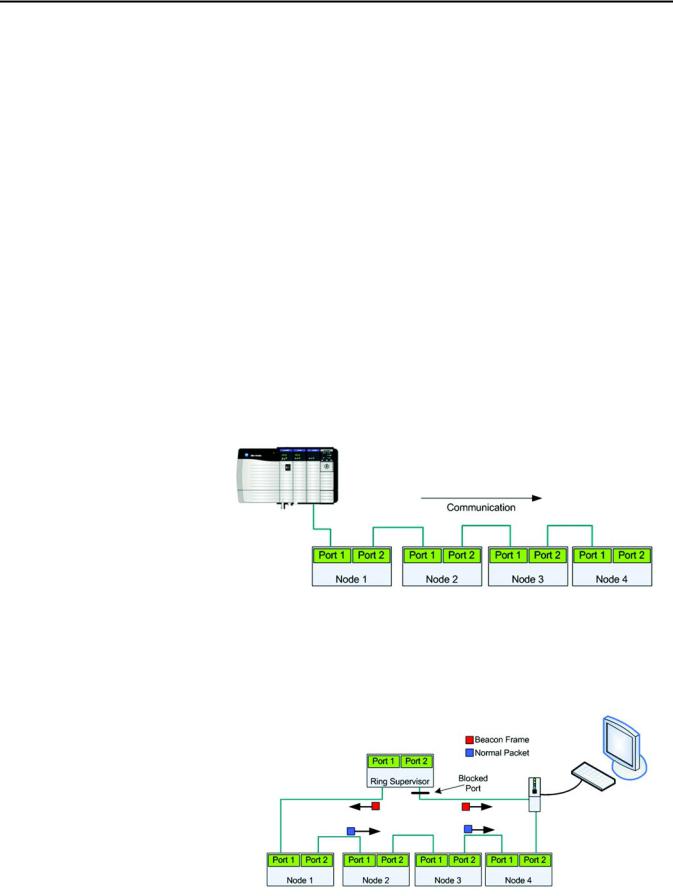
Embedded dual port switch — ArmorStart LT EtherNet/IP version includes a dual port 10/100 mb/s ethernet switch that supports linear or Device Level Ring (DLR) topology.
Figure 1 - Linear Topology
Device Level Ring (DLR) - ArmorStart LT EtherNet/IP version offers DLR support with beacon frame performance. DLR provides a single fault tolerant network solution for EtherNet/IP.
Figure 2 - DLR with Beacon Performance — No Fault
20 |
Rockwell Automation Publication 290E-UM001B-EN-P - June 2012 |
Product Overview |
Chapter 1 |
|
|
Figure 3 - DLR with Beacon Performance — Fault
In this example the fault is precisely identified by the link status message and the supervisor opens the blocked port to allow network traffic to continue normally.
IEEE 1588 transparent clock —ArmorStart LT EtherNet/IP version supports the IEEE 1588 transparent clock when used with precision time protocols (PTP). A transparent clock measures and adjusts for packet delays, therefore removing the negative effects that these variations can cause within a synchronized distributed network of devices.
Embedded web server — ArmorStart LT EtherNet/IP version offers a web server that can be accessed via a standard internet browser. The web server provides status, diagnostics, and configuration capabilities.
E-mail notification — ArmorStart LT via the embedded web server, supports configuration of the Simple Mail Transfer Protocol (SMTP). Once properly configured, the motor controller will e-mail the user with specific fault/trip messages.
Rockwell Automation Publication 290E-UM001B-EN-P - June 2012 |
21 |

Chapter 1 Product Overview
Factory-Installed Options |
Internal power supply (IPS) — ArmorStart LT offers the user an optional |
|
24V DC internal power supply. The internal power supply provides all control |
|
and I/O power needs and is sourced from the incoming 3-phase power. This |
|
eliminates the need to run separate control power to each unit, reducing |
|
installation time and cost. The local at-motor disconnect will remove power |
|
from the motor terminals and outputs when in the OFF condition. |
|
Hand/Off/Auto (HOA) keypad — ArmorStart LT offers an optional local |
|
Hand-Off-Auto keypad. This key pad allows local start/stop motor control |
|
regardless of PLC status. This option can be used for troubleshooting or |
|
maintenance operations. The HOA can also be disabled when local control |
|
is not allowed, using parameter 67. |
|
Source brake — ArmorStart LT provides an optional, internally-controlled |
|
electromechanical motor brake contactor. The motor brake power is sourced |
|
from 3-phase power, L1 and L2. |
|
Quick disconnect gland — ArmorStart LT offers a plug -n- play solution that |
|
simplifies wiring and installation. These factory installed quick disconnect |
|
receptacles provide connectivity to ArmorConnect® media for three-phase, |
|
control, and motor connections. The cables are ordered separately. |
22 |
Rockwell Automation Publication 290E-UM001B-EN-P - June 2012 |
Product Overview |
Chapter 1 |
|
|
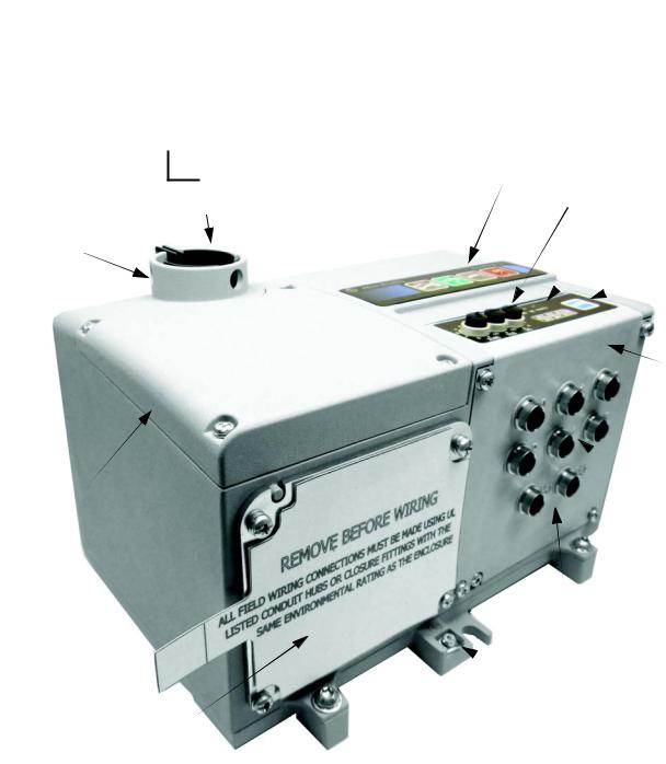
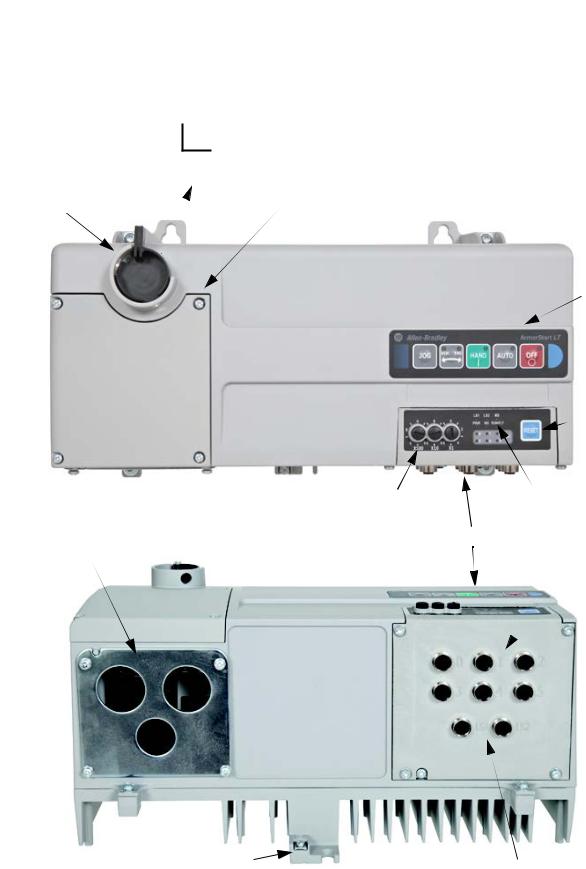
ArmorStart LT Characteristics
Figure 4 - Bulletin 290E/291E ArmorStart LT
0 Off
1 On
On/Off Switch
LockOut/TagOut Provision
Wiring Access
Gland Plate – Conduit/Cord Grip or
ArmorConnect® Media (optional)
HOA Keypad (optional)
IP Address Switches
Status and Diagnostic LEDs
 Reset
Reset
ECM (Electronic
Control Module)
 6 Configurable I/Os
Dual Port EtherNet/IP
(This is replaced by a DeviceNet connector, when DeviceNet communication is selected)
 Protective Earth (PE)
Rockwell Automation Publication 290E-UM001B-EN-P - June 2012 |
23 |

Chapter 1 Product Overview
Catalog Number Explanation Examples given in this section are for reference purposes. This basic explanation should not be used for product selection; not all combinations will produce a
valid catalog number.
290 E - F A Z - G1 - Option 1 - Option 2
—— — — — — —— ——
a |
b |
c |
d |
e |
f |
g |
h |
a
Bulletin Number
Code |
Description |
290Full-Voltage Starter
291Reversing Starter
b
Communications
Code |
Description |
EEtherNet/IP
DDeviceNet
|
c |
|
Enclosure Type |
|
|
Code |
Description |
FUL Type 4/12
|
d |
|
Overload Selection |
|
|
Code |
Description |
A0.25…3.5 A
B1.1…7.6 A
e
Control Voltage
Code |
Description |
ZExternal 24V DC control power
PInternal power supply
|
f |
|
Gland Plate Options |
|
(Power and Motor) |
|
|
Code |
Description |
G1 |
Conduit entry |
G2 |
ArmorConnect |
G3 |
Gland Kits |
|
|
|
g |
|
Option 1 |
|
|
Code |
Description |
3Hand/Off/Auto selector keypad
3FR |
Hand/Off/Auto selector keypad with |
|
Forward/Reverse |
|
h |
|
Option 2 |
|
|
Code |
Description |
blank |
No option |
|
|
|
|
IP66/UL Type 4 is available with all gland options. UL Type 4/12 is available with G1 and G3 gland option.See selection guide 290-SG001_-EN-P Accessories section for gland configurations and ordering.
Leave blank unless there is a customer-specific option defined by the factory.
24 |
Rockwell Automation Publication 290E-UM001B-EN-P - June 2012 |
Product Overview |
Chapter 1 |
|
|
ArmorStart LT Characteristics
Figure 5 - Bulletin 294E ArmorStart LT
0
Off
1 On
On/Off Switch
Wiring Access
LockOut/TagOut Provision
Gland Plate – Conduit/Cord Grip or
ArmorConnect Media (optional)
Hand-Off-Auto
Keypad (optional)
 Reset
Reset
IP Address Switches |
Status and Diagnostic LEDs |
|
ECM (Electronic Control Module) |
6 Configurable I/Os |
|
Protective Earth (PE) |
|
Dual Port EtherNet/IP |
|
|
|
|
Bottom View |
(This is replaced by a DeviceNet connector, |
|
when DeviceNet communication is selected) |
|
|
|
Rockwell Automation Publication 290E-UM001B-EN-P - June 2012 |
25 |
Chapter 1 Product Overview
Catalog Number Explanation Examples given in this section are for reference purposes. This basic explanation should not be used for product selection; not all combinations will produce a
valid catalog number.
294 |
E |
- F |
D1P5 |
Z |
- G1 |
- Option 1 |
- Option 2 |
— |
— |
— |
— |
— |
— |
—— |
—— |
a |
b |
c |
d |
e |
f |
g |
h |
|
a |
|
Bulletin Number |
|
|
Code |
Description |
294 |
VFD Starter |
|
|
b
Communications
Code |
Description |
EEtherNet/IP
DDeviceNet
|
c |
|
Enclosure Type |
|
|
Code |
Description |
FUL Type 4/12
|
d |
|
Output Current |
|
|
Code |
Description |
D1P5 |
1.5 A (0.4 kW), 0.5 Hp |
D2P5 |
2.5 A (0.75 kW), 1.0Hp |
D4P2 |
3.6 A (1.5 kW), 2.0Hp |
|
|
e
Control Voltage
Code |
Description |
ZExternal 24V DC control power
PInternal power supply
|
f |
|
Gland Plate Options |
|
(Power and Motor) |
|
|
Code |
Description |
G1 |
Conduit entry |
G2 |
ArmorConnect |
G3 |
Gland kits |
|
|
|
g |
|
Option 1 |
|
|
Code |
Description |
3Hand/Off/Auto selector keypad with Jog
function
|
h |
|
Option 2 |
|
|
Code |
Description |
SB |
Source Brake |
blank |
No option |
|
|
|
|
IP66/UL Type 4 is available with all gland options. UL Type 4/12 is available with G1 and G3 gland option.See selection guide 290-SG001_-EN-P Accessories section for gland configurations and ordering.
Leave blank unless there is a customer-specific option defined by the factory.
26 |
Rockwell Automation Publication 290E-UM001B-EN-P - June 2012 |
Product Overview |
Chapter 1 |
|
|
Basic Operation |
Group Motor Installations for USA and Canada Markets |
The ArmorStart LT Distributed Motor controllers are listed for use with each other in group installations per NFPA 79, Electrical Standard for Industrial Machinery and NFPA 70, the National Electrical Code. When applied according to the group motor installation requirements, two or more motors are permitted on a single branch circuit. Group Motor Installation has been successfully used for many years in the USA and Canada.
Note: For additional information regarding group motor installations with the
ArmorStart LT Distributed Motor Controller, see Appendix A.
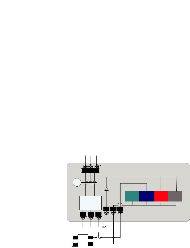
Control Circuit
ArmorStart LT accepts a 24V DC Class 2 input power supply for switched and unswitched power. The control voltage provides power to the inputs (unswitched) and outputs (switched). Unswitched control voltage is used to ensure no loss of network connectivity, sensor, or other field input status under normal operation. The control power terminal connections are labeled A1, A2, and A3. Switched power is identified as (+A1) (-A2). Unswitched power is identified as (+A3) (-A2).
As an option, ArmorStart LT can be supplied with an internal power supply (IPS) eliminating the need for an external control power. The IPS is sourced from the line side of 3-phase power and is not impacted by the status of the local at-motor disconnect switch.
Figure 6 - Control Circuit Wiring Diagram — Single External Power Supply
L1 |
L2 |
L3 |
|
|
|
|
ArmorStart LT |
|
|
|
|
|
|||
Off |
|
|
Switched Control Power |
|
|
|
|
|
|
|
|
|
|
|
|
|
|
|
|
Unswitched Control Power |
|
|
|
Disconnect |
|
* |
|
|
|
|
|
|
|
|
|
|
|
|
|
|
|
|
|
EtherNet |
Inputs |
Outputs |
Motor |
|
|
|
|
Comms |
Control |
||
|
Motor |
|
|
|
|
||
|
|
|
|
|
|
|
|
Controller |
|
A3 |
|
|
|
||
|
|
A1 |
A2 |
|
|
|
|
T1 |
T2 |
T3 |
|
|
|
|
|
|
|
|
|
* Control power output is determined by disconnect status |
|
||
L |
+ |
|
|
|
|
|
|
24VDC |
- |
|
|
|
|
|
|
N |
|
|
|
|
|
|
|
Class 2 |
|
|
|
|
|
|
|
External |
|
|
|
|
|
|
|
24VDC Power |
|
|
|
|
|
|
|
Supply |
|
|
|
|
|
|
|
Rockwell Automation Publication 290E-UM001B-EN-P - June 2012 |
27 |
Chapter 1 Product Overview
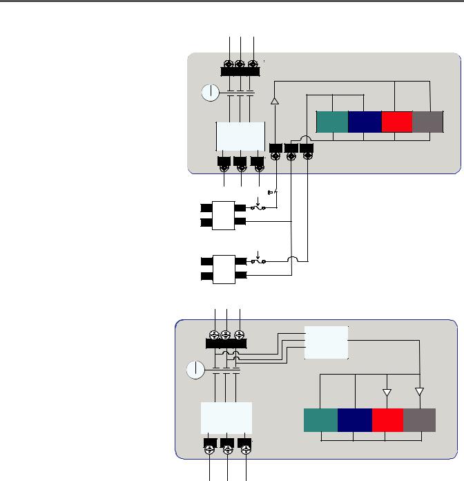
Figure 7 - Control Circuit Wiring Diagram — Multiple External Power Supplies
|
|
|
|
|
|
|
ArmorStart LT |
|
|
L1 |
L2 |
L3 |
Switched Control Power |
|
|
|
|
|
Off |
|
|
|
|
|
||
|
|
|
|
|
|
|
|
|
|
|
|
|
|
Unswitched Control Power |
|
|
|
|
Disconnect |
|
* |
|
|
|
|
|
|
|
|
|
|
|
|
|
|
|
|
|
|
|
EtherNet |
Inputs |
Outputs |
Motor |
|
|
|
|
|
Comms |
Control |
||
|
|
Motor |
|
|
|
|
||
|
|
|
|
|
|
|
|
|
|
Controller |
|
A3 |
|
|
|
||
|
|
|
A1 |
A2 |
|
|
|
|
|
T1 |
T2 |
T3 |
|
|
|
|
|
|
|
|
|
|
* Control power output is determined by disconnect status |
|
||
Class 2 |
L |
+ |
|
|
|
|
|
|
External Switched |
24VDC |
|
|
|
|
|
|
|
24VDC Power Supply |
- |
|
|
|
|
|
|
|
N |
|
|
|
|
|
|
||
|
|
|
|
|
|
|
||
Class 2 |
L |
+ |
|
|
24VDC |
||
External Unswitched |
|
||
N |
- |
||
24VDC Power Supply |
Figure 8 - Control Circuit Wiring Diagram — Internal Power Supply (optional)
L1 |
L2 |
L3 |
Off |
|
|
Disconnect
Motor
Controller
T1 
 T2
T2 
 T3
T3
ArmorStart LT
Internal Power
Supply
* |
* |
EtherNet |
Inputs |
Outputs |
Motor |
|
Comms |
Control |
|||
|
|
* Control power output is determined by disconnect status
28 |
Rockwell Automation Publication 290E-UM001B-EN-P - June 2012 |

Product Overview |
Chapter 1 |
|
|
Motor Circuit
The ArmorStart LT Distributed Motor Controllers are rated to operate the following types of three-phase squirrel-cage induction motors:
Bulletin 290E/291E:
0.5 Hp (0.37 kW) to 5 Hp (3 kW) @ 480/277V AC Bulletin 294E:
0.5 Hp (0.37 kW) to 2 Hp (1.5 kW) @ 480/277V AC
Local I/O
The ArmorStart LT provides as standard, 6 user configurable I/O points. By default, all points are configured as an Input. When not using the AOP, the user will need to refer to parameter 49 [IOPointConfiguration], to define an output point.
When using the AOP, the I/O point is configured from the General screen
in the Module Definition section by clicking the “Change” button, see Figure 9. This allows user to view and configure the I/O mix, refer to Figure 10.
Figure 9 - Defining I/O Point
Figure 10 - Current I/O Point Configuration
Rockwell Automation Publication 290E-UM001B-EN-P - June 2012 |
29 |

Chapter 1 Product Overview
Overload Protection
The ArmorStart LT Distributed Motor Controller incorporates, as standard, electronic motor overload protection. This overload protection is accomplished
electronically with an I2t algorithm. The ArmorStart LT’s overload protection is programmable via the communication network, providing the user with greater flexibility.
The Bulletin 290E/291E includes programmable overload Class 10, 15, and 20 protection. The Bulletin 294E provides overload protection: 150% for 60s and 200% for 3s.
Refer to Chapter 6, Specifications, for additional information.
Mode of Operation |
Full-Voltage Start |
|||
Bulletin 290E/291E |
This method is used in applications requiring across-the-line starting, in which |
|||
|
||||
|
full inrush current and locked-rotor torque are realized. The ArmorStart LT |
|||
|
Bulletin 290E offers full-voltage starting and Bulletin 291E offers full-voltage |
|||
|
starting for reversing applications, from 0.5 Hp (0.37 kW) to 5 Hp (3 kW) at |
|||
|
480Y/277V AC, 3-phase power. |
|||
|
Figure 11 - Full-Voltage Start |
|||
|
100% |
|
|
|
|
|
|
|
|
|
|
|
|
|
|
Percent |
|
|
|
|
Voltage |
|
|
|
|
|
|
|
|
|
|
|
Time (seconds) |
|
30 |
Rockwell Automation Publication 290E-UM001B-EN-P - June 2012 |
Loading...