


Allen-Bradley
IMC S Class
Compact Motion
Controller
(Cat. No. 4100-999-122)
Installation
and Setup
Manual

Important User
Information
Because of the variety of uses for the products described in this publication, those responsible for the application and use of this control equipment must satisfy themselves that all necessary steps have been taken to assure that each application and use meets all performance and safety requirements, including any applicable laws, regulations, codes and standards.
The illustrations, charts, sample programs and layout examples shown in this guide are intended solely for purposes of example. Since there are many variables and requirements associated with any particular installation, Allen-Bradley does not assume responsibility or liability (to include intellectual property liability) for actual use based upon the examples shown in this publication.
Allen-Bradley publication SGI-1.1, Safety Guidelines for the Application, Installation, and Maintenance of Solid-State Control
(available from your local Allen-Bradley office), describes some important differences between solid-state equipment and electromechanical devices that should be taken into consideration when applying products such as those described in this publication.
Reproduction of the contents of this copyrighted publication, in whole or in part, without written permission of Allen-Bradley Company, Inc., is prohibited.
Throughout this manual we use notes to make you aware of safety considerations:
ATTENTION: Identifies information about practices or circumstances that can lead to personal injury or
! death, property damage or economic loss.
Attention statements help you to:
∙identify a hazard
∙avoid the hazard
∙recognize the consequences
Important: Identifies information that is critical for successful application and understanding of the product.
GML, ULTRA, IMC, SCAN bus, Flex I/O, DTAM, PanelView, and SLC are trademarks; PLC is a registered trademark of Allen-Bradley Company, Inc.
Table of Contents |
E |
|
|
Preface
Who Should Use this Manual ........................ |
P-1 |
Purpose of this Manual .................................. |
P-1 |
Safety Precautions .......................................... |
P-1 |
Contents of this Manual ................................. |
P-2 |
Related Documentation ............................... |
P-3 |
Product Receiving & Storage Responsibility. P-3 |
|
Allen-Bradley Support ................................... |
P-3 |
Local Product Support ................................. |
P-4 |
Technical Product Assistance ...................... |
P-4 |
Chapter 1 – Safety
Read This Manual .......................................... |
1-1 |
Chapter 2 – Introduction
IMC-S/23x Description.................................. |
2-1 |
Features .......................................................... |
2-2 |
Model Numbering System ............................. |
2-4 |
Pre-Engineered Cable Assemblies ................. |
2-4 |
Mechanical Specifications ............................. |
2-5 |
Front Panel Layout ...................................... |
2-5 |
Mounting and Clearance Dimensions .......... |
2-6 |
General Specifications ................................... |
2-6 |
Environmental Specifications ....................... |
2-7 |
Electrical Specifications ................................. |
2-7 |
Encoder Input Specifications ......................... |
2-7 |
Servo Output Specifications........................... |
2-8 |
Dedicated Discrete I/O Specifications ........... |
2-8 |
Serial I/O Specifications ................................ |
2-9 |
DH-485 Specifications ................................... |
2-9 |
Flex I/O Compatibility Specifications ......... |
2-10 |
Servo Performance Specifications ............... |
2-10 |
Servo Gain Units ....................................... |
2-11 |
Remote I/O Adapter Specifications ............. |
2-11 |
AxisLink Specifications ............................... |
2-13 |
Publication 999-122 – January 1997
EE |
Table of Contents |
|
|
Chapter 3 – Technical Overview
Digital Control Loop ...................................... |
3-1 |
Encoders ......................................................... |
3-2 |
Encoder Counter ............................................ |
3-3 |
Software Feedback Calculations .................... |
3-4 |
Servo Amplifiers and Motors ......................... |
3-5 |
High Level Motion Functions ........................ |
3-6 |
Indexing and Jogging ................................... |
3-7 |
Backlash Compensation .............................. |
3-7 |
Electronic Cam ............................................ |
3-7 |
Electronic Gearing ....................................... |
3-7 |
Interpolation ................................................. |
3-8 |
Velocity Feedforward .................................... |
3-8 |
CPU Watchdog .............................................. |
3-9 |
Software Overtravel Limits............................ |
3-9 |
Serial Communication .................................... |
3-9 |
DH-485 Communication .............................. |
3-10 |
Axis-Specific Discrete I/O ........................... |
3-10 |
Home Limit Switch Input .......................... |
3-10 |
Overtravel Limit Switch Inputs ................. |
3-10 |
Drive Fault Output ..................................... |
3-11 |
Drive Enable Output .................................. |
3-11 |
Position Registration Inputs ....................... |
3-11 |
Status LEDs .................................................. |
3-11 |
General Purpose Discrete I/O ...................... |
3-12 |
The Imaginary Axis ..................................... |
3-12 |
Remote I/O (Optional) ................................. |
3-12 |
AxisLink (Optional)..................................... |
3-12 |
Chapter 4 – Installation and Hookup
Introduction .................................................... |
4-1 |
Complying with European Union Directives . 4-3
EMC Directive ............................................. |
4-3 |
Low Voltage Directive ................................. |
4-3 |
Installing the IMC-S/23x ............................... |
4-6 |
Configuring the IMC-S/23x ........................... |
4-7 |
Configure the Serial Ports ............................ |
4-8 |
Select the Registration Input Voltage ........ |
4-11 |
Select the Encoder Power Voltage ............. |
4-12 |
Select the Servo Output Format................. |
4-14 |
Serial Communications Devices .................. |
4-15 |
Publication 999-122 – January 1997
Table of Contents |
EEE |
|
|
Serial Communication Protocol ................. |
4-15 |
Connecting RS-232 Devices ...................... |
4-16 |
Connecting RS-422 Devices ...................... |
4-18 |
Connecting Encoders ................................... |
4-19 |
AB 1391B-ES & 1391-DES Drives .......... |
4-20 |
AB 845F, 845H, & 845T Encoders ........... |
4-20 |
AB 845K Encoders .................................... |
4-21 |
AB 845P Encoders ..................................... |
4-21 |
Other Encoders .......................................... |
4-22 |
Connecting Servo Amplifiers ....................... |
4-22 |
AB 1391B-ES & 1391-DES Drives .......... |
4-23 |
Other Servo Amplifiers ............................. |
4-23 |
Connecting Hydraulic Valves ...................... |
4-24 |
Connecting Axis-Specific Discrete I/O........ |
4-25 |
The Drive Enable Outputs ......................... |
4-26 |
The Drive Fault Inputs............................... |
4-26 |
Connecting Registration Sensors ................. |
4-27 |
Using the Registration Inputs .................... |
4-28 |
Connecting the CPU Watchdog ................... |
4-29 |
Connecting Flex I/O ..................................... |
4-30 |
Connect the I/O Power Supply ..................... |
4-30 |
Connect the AC Power ................................. |
4-31 |
Connecting Remote I/O (Optional) .............. |
4-32 |
Connecting AxisLink (Optional) ................. |
4-33 |
AxisLink for Standard Operation .............. |
4-34 |
AxisLink for Extended Length Operation . 4-35 |
|
Connecting DH-485 (Optional) ................... |
4-36 |
Chapter 5 – Understanding IMC-S/23x Setups |
|
The Setup Menus ........................................... |
5-1 |
Application Setup Menu .............................. |
5-1 |
Machine Setup Menu ................................... |
5-1 |
Hookup Diagnostics Menu .......................... |
5-1 |
Servo Setup Menu ....................................... |
5-2 |
Using the Setup Menus .................................. |
5-2 |
Passwords .................................................... |
5-2 |
Toggling ....................................................... |
5-2 |
Disabling Feedback ..................................... |
5-3 |
Disabling DH-485 ........................................ |
5-3 |
Loading Setup Values .................................. |
5-4 |
Selecting a Setup Menu ............................... |
5-4 |
Selecting an Axis ......................................... |
5-4 |
Editing Parameter Values ............................. |
5-5 |
Publication 999-122 – January 1997
EL |
Table of Contents |
|
|
Application Setup Menu ................................ |
5-5 |
Upload Inhibit .............................................. |
5-6 |
Editing the AxisLink Configuration .............. |
5-6 |
Editing the DH-485 Configuration ................ |
5-6 |
Maximum Node Address............................. |
5-7 |
Network Node Address ............................... |
5-7 |
Baud Rate .................................................... |
5-7 |
Token Hold Factor ....................................... |
5-7 |
Editing the Axis Setup Parameters................. |
5-8 |
Axis Configuration ...................................... |
5-8 |
Virtual Axes ................................................. |
5-8 |
The Imaginary Axis ................................... |
5-10 |
Rotary Axes ............................................... |
5-10 |
Position Units ............................................ |
5-10 |
Display Fields ............................................ |
5-11 |
Averaged Velocity Timebase ..................... |
5-11 |
Move and Jog Profiles ............................... |
5-12 |
Trapezoidal ................................................ |
5-12 |
S Curve ...................................................... |
5-13 |
Parabolic .................................................... |
5-13 |
Backlash Compensation ............................ |
5-14 |
Editing the Axis Fault Action Configuration 5-14 Editing the Direct Command Mode Configuration 5-16 Editing the Operator Interface Configuration 5-17
Editing the Runtime Display Configuration |
5-18 |
Editing the Serial Port Configuration ........... |
5-20 |
Editing the RIO Configuration ..................... |
5-21 |
RIO Adapter Channel ................................ |
5-21 |
RIO Baud Rate ........................................... |
5-22 |
RIO Rack Size ........................................... |
5-22 |
RIO Rack Address ..................................... |
5-23 |
RIO Starting Group ................................... |
5-23 |
RunningApplication Program on Power-Up 5-23
Machine Setup Menu ................................... |
5-24 |
Editing the Feedback Configuration ............ |
5-25 |
Conversion Constant (K) ........................... |
5-25 |
Unwind ...................................................... |
5-26 |
Unwind Reference Point............................ |
5-26 |
Encoder Loss Detection............................. |
5-27 |
Editing the Overtravel Configuration .......... |
5-27 |
Overtravel Limit Switches ......................... |
5-28 |
Software Travel Limits .............................. |
5-28 |
Publication 999-122 – January 1997
Table of Contents |
L |
|
|
Editing the Homing Configuration .............. |
5-29 |
Home Position ........................................... |
5-29 |
Active Homing .......................................... |
5-30 |
Homing Without a Limit Switch or Marker 5-30 |
|
Homing to an Encoder Marker .................. |
5-30 |
Homing to a Limit Switch ......................... |
5-31 |
Homing to a Limit Switch and Marker...... |
5-32 |
Limit Switch Contacts ............................... |
5-32 |
Absolute Homing....................................... |
5-33 |
Absolute_MV ............................................ |
5-34 |
Absolute_Serial ......................................... |
5-35 |
Passive Homing ......................................... |
5-35 |
Editing the Servo Configuration .................. |
5-36 |
Dual Loop Control ..................................... |
5-36 |
Servo Output Limiting ............................... |
5-39 |
Drive Fault Input ....................................... |
5-40 |
Editing the Positioning Configuration ......... |
5-40 |
Position Lock Tolerance ............................ |
5-40 |
Backlash Offset.......................................... |
5-41 |
Approach Direction ................................... |
5-41 |
Hookup Diagnostics Menu ........................... |
5-42 |
Checking Motors and Encoders ................... |
5-43 |
Testing Encoders .......................................... |
5-45 |
Editing the Motor/Encoder Polarity ............. |
5-47 |
Tuning Velocity Loop Servo Drives ............ |
5-47 |
Adjusting Offset ......................................... |
5-47 |
Digital Battery Box .................................... |
5-48 |
Checking Encoder Markers.......................... |
5-50 |
Align Absolute Transducers ......................... |
5-51 |
Checking The Discrete I/O .......................... |
5-53 |
Checking the Dedicated Discrete Inputs |
... 5-53 |
Checking the Dedicated Discrete Outputs . 5-54 |
|
Checking Flex I/O Discrete Inputs ............ |
5-54 |
Checking Flex I/O Discrete Outputs ......... |
5-55 |
Checking Flex I/O Analog Inputs .............. |
5-56 |
Checking Flex I/O Analog Outputs ........... |
5-57 |
Servo Setup Menu ........................................ |
5-58 |
The Servo Loop Gains ................................. |
5-58 |
Velocity Gain ............................................. |
5-59 |
Proportional Gain ...................................... |
5-59 |
Integral Gain .............................................. |
5-59 |
Feedforward Gain ...................................... |
5-60 |
Publication 999-122 – January 1997
LE |
Table of Contents |
|
|
Self-Tuning the Servo Gains ........................ |
5-60 |
Using the Position Error Integrator ........... |
5-66 |
Using Velocity Feedforward ...................... |
5-66 |
Tuning Faults ............................................... |
5-67 |
Aborted by Escape! ................................... |
5-67 |
Encoder Fault! ........................................... |
5-67 |
Hit Hardware Overtravel Limit! ................ |
5-67 |
Position Error Tolerance Exceeded! .......... |
5-68 |
Drive Fault Detected! ................................ |
5-68 |
Manually Tuning the Loop Gains 5-68 |
|
Setting the Drive Offset & Deadband Comp 5-69
Setting the Velocity Gain ........................... |
5-69 |
Setting the Proportional Gain .................... |
5-70 |
Setting the Integral Gain ............................ |
5-71 |
Setting the Feedforward Gain .................... |
5-72 |
Setting the Position Error Tolerance.......... |
5-72 |
Saving Setup Values .................................... |
5-73 |
Setup Menu Reference ................................. |
5-74 |
Chapter 6 – Setting Up Your IMC-S/23x Using GML
Chapter Objectives ......................................... |
6-1 |
General Startup Precautions ........................... |
6-1 |
Setting Up Your Compact.............................. |
6-2 |
Before You Begin ........................................ |
6-2 |
Preparing the System ................................... |
6-2 |
Getting Started ............................................. |
6-3 |
Defining Preferences ................................. |
6-3 |
Defining Your Controller and Its Options .... |
6-4 |
Defining Your Axes................................... |
6-5 |
Applying Power ........................................... |
6-6 |
Establishing Communication....................... |
6-6 |
Downloading Your Diagram ..................... |
6-7 |
Testing Motor Connections & Defining Dir 6-7 |
|
Testing the Encoder Marker ...................... |
6-8 |
Tuning a Velocity Loop ............................. |
6-8 |
Tuning Servo Parameters .......................... |
6-9 |
Saving Your Parameters .......................... |
6-10 |
Chapter 7 – Troubleshooting |
|
Chapter Objectives ......................................... |
7-1 |
Understanding How to Detect a Problem ...... |
7-1 |
Replacing Modules ........................................ |
7-2 |
Before You Begin ........................................ |
7-2 |
Publication 999-122 – January 1997
Table of Contents |
LEE |
|
|
Removing a CPU Module............................ |
7-2 |
Installing a Replacement CPU Module ....... |
7-3 |
Removing a Power Supply Module ............. |
7-3 |
Installing a Replacement Power Supply ..... 7-4 |
|
Understanding Status LEDs ........................... |
7-5 |
Understanding the System OK LED .............. |
7-5 |
Understanding System Faults ......................... |
7-6 |
Finding Faults .............................................. |
7-6 |
Viewing Instantaneous Status.................... |
7-6 |
Viewing Continuous Status ....................... |
7-7 |
Troubleshooting General System Problems... |
7-8 |
Appendix A – Cable Information |
|
Introduction ................................................... |
A-1 |
4100-CCF1 or 4100-CCF3 ......................... |
A-2 |
4100-CCS15F ............................................. |
A-2 |
4100-CCA15F ............................................ |
A-3 |
4100-CCW15F ............................................ |
A-4 |
4100-RCS3T ............................................... |
A-4 |
4100-CCAQB ............................................. |
A-5 |
Publication 999-122 – January 1997
LEEE |
Table of Contents |
|
|
Publication 999-122 – January 1997
Preface P-1
Preface
Read this preface to familiarize yourself with the rest of the manual. This preface covers the following topics:
∙who should use this manual
∙the purpose of this manual
∙general safety precautions
∙receiving and storage information
∙Allen-Bradley support
Who Should Use this Manual
Purpose of this Manual
Safety Precautions
Use this manual if you are responsible for designing, installing, programming, or troubleshooting the Allen-Bradley IMC S Class Compact.
If you do not have a basic understanding of the Compact, contact your local Allen-Bradley representative for information on available training courses before using this product.
This manual is a installation and setup guide for the Compact. It gives you an overview of the Compact and describes the procedures you use to install, set up, use, and troubleshoot the Compact.
The following general precautions apply to the Compact:
ATTENTION: Only those familiar with the Compact and associated machinery should plan or implement the ! installation, startup, and subsequent maintenance of the
system. Failure to comply can result in personal injury and/or equipment damage.
ATTENTION: This product contains stored energy devices. To avoid hazard of electrical shock, verify that all voltage on the capacitors has been discharged before attempting to service, repair, or remove this unit. You should only attempt the procedures in this manual if you are qualified to do so and familiar with solid-state control equipment and the safety procedures in publication NFPA 70E.
ATTENTION: The system integrator is responsible for local safety and electrical codes.
Publication 999-122 - January 1997

P-2 |
Preface |
ATTENTION: An incorrectly applied or installed Compact can result in component damage or a reduction
! in product life. Wiring or application errors, such as undersizing the motor, incorrect or inadequate AC supply, or excessive ambient temperatures can result in malfunction of the product.
ATTENTION: This product contains ESD (Electrostatic Discharge) sensitive parts and assemblies. Static control precautions are required when installing, testing, servicing, or repairing this assembly. Component damage can result if ESD control procedures are not followed. If you are not familiar with static control procedures, refer to Allen-Bradley publication 8000-4.5.2, Guarding Against Electrostatic Damage or any other applicable ESD Protection Handbook.
Contents of this Manual
Chapter |
Title |
Contents |
|
|
|
|
|
|
|
Describes the purpose, background, and scope |
|
|
Preface |
of this manual. Also specifies the audience for |
|
|
|
whom this manual is intended. |
|
|
|
|
|
1 |
Safety |
Lists safety information regarding the Compact. |
|
|
|
|
|
2 |
Introduction |
Provides a feature overview of the Compact. |
|
|
|
|
|
3 |
Technical Overview |
Provides a technical overview of the Compact. |
|
|
|
|
|
4 |
Installation and |
Provides information that allows you to install and |
|
Hookup |
hook up your Compact. |
||
|
|||
|
|
|
|
|
Understanding the |
Provides information that allows you to |
|
5 |
understand the setup procedures for the |
||
IMC-S23x Setup |
|||
|
Compact. |
||
|
|
||
|
|
|
|
6 |
Setting Up your |
Provides setup procedures for the Compact. |
|
Compact |
|||
|
|
||
|
|
|
|
7 |
Troubleshooting |
Explains how to interpret and correct problems |
|
with your Compact. |
|||
|
|
||
|
|
|
|
Appendix A |
Cable Information |
Provides information about the cables used with |
|
the Compact. |
|||
|
|
||
|
|
|
Publication 999-122 - January 1997
Preface |
P-3 |
Related Documentation
The following documents contain additional information concerning related Allen-Bradley products. To obtain a copy, contact your local Allen-Bradley office or distributor.
For |
Read This Document |
Document Number |
|
|
|
|
|
A description and specifications for the Compact |
Compact Motion Controller Product Data |
4100-2.3 |
|
|
|
|
|
A user guide for GML programming to be used with the Compact. |
GML Programming Manual |
GML-DOC-S |
|
|
|
|
|
An overview of the Flex I/O products |
Flex I/O Product Profile |
1794-1.14 |
|
|
|
|
|
Specifications for the Flex I/O products |
Flex I/O Product Data |
1794-2.1 |
|
|
|
|
|
|
|
Published by the |
|
An article on wire sizes and types for grounding electrical equipment |
National Electrical Code |
National Fire |
|
Protection Association |
|||
|
|
||
|
|
of Boston, MA. |
|
|
|
|
|
A complete listing of current Allen-Bradley documentation, including |
|
|
|
ordering instructions. Also indicates whether the documents are |
Allen-Bradley Publication Index |
SD499 |
|
available on CD-ROM or in multi-languages |
|
|
|
|
|
|
|
A glossary of industrial automation terms and abbreviations |
Allen-Bradley Industrial Automation Glossary |
AG-7.1 |
|
|
|
|
|
Schematics related to the Compact. |
Schematics |
4100-5.0.01 |
|
|
|
|
Compact Product
Receiving and Storage
Responsibility
You, the customer, are responsible for thoroughly inspecting the equipment before accepting the shipment from the freight company. Check the item(s) you receive against your purchase order. If any items are obviously damaged, it is your responsibility to refuse delivery until the freight agent has noted the damage on the freight bill. Should you discover any concealed damage during unpacking, you are responsible for notifying the freight agent. Leave the shipping container intact and request that the freight agent make a visual inspection of the equipment.
Leave the product in its shipping container prior to installation. If you are not going to use the equipment for a period of time, store it:
∙in a clean, dry location
∙within an ambient temperature range of -40 to 70° C (-40 to 158° F)
∙within a relative humidity range of 5% to 95%, non-condensing
∙in an area where it cannot be exposed to a corrosive atmosphere
∙in a non-construction area
Allen-Bradley Support
Allen-Bradley offers support services worldwide, with over 75 Sales/Support Offices, 512 authorized Distributors and 260 authorized Systems Integrators located throughout the United States alone, plus Allen-Bradley representatives in every major country in the world.
Publication 999-122 - January 1997
P-4 |
Preface |
Local Product Support
Contact your local Allen-Bradley representative for:
∙sales and order support
∙product technical training
∙warranty support
∙support service agreements
Technical Product Assistance
If you need to contact Allen-Bradley for technical assistance, please review the information in the Troubleshooting chapter first. Then call your local Allen-Bradley representative. For the quickest possible response, we recommend that you have the catalog numbers of your products available when you call. The Rockwell Automation Technical Support number is (603) 443-5419.
Publication 999-122 - January 1997
Chapter 1
Safety
Read This Manual
Read and understand this instruction manual. It provides the necessary information to allow you to install, connect, and set up your IMCñS/23x for safe, reliable operation.
ATTENTION: DANGEROUS MACHINERY!
Operation and maintenance of automatic equipment ! involves potential hazards. Control Operators, Setup
Personnel, and Programmers should each take precautions to avoid injury.
Injury and entanglement may occur if hands and limbs come in contact with moving machinery. KEEP HANDS CLEAR of dangerous moving machinery. Loose fitting clothing or ties can become entangled in the machinery. These items should not be worn while operating, servicing, or programming the machine.
ATTENTION: HIGH VOLTAGES!
Electric shock can kill. Be sure the controller is safely ! installed in accordance with the Installation and
Hookup Section of this manual. Avoid contact with electrical wires and cabling while power is on. The electrical cabinet should be opened only by trained service personnel.
ATTENTION: STATIC CONTROL!
The internal modules of the IMC S Class Compact motion ! controller contain staticñsensitive electronic
components. Remove and handle the internal modules only at a staticñsafeguarded work area. Failure to do so may result in a drastically shortened life of your motion controller.
A disposable wristñstrap for grounding yourself is included with this product. Please follow the directions for use of this strap when removing and handling the motion controllers internal modules.
Publication 999-122 - January 1997

1-2 Safety
Publication 999-122 - January 1997

Chapter 2
Introduction
IMC-S/23x Description
The IMC-S/23x is a compact, rugged, microprocessor-based twoor four-axis servo motion controller. By including the logic and field power supplies, the IMC-S/23x provides a completely programmable, stand-alone motion and logic controller suitable for a wide variety of industrial applications.
The IMC-S/23x, in conjunction with external drive systems and feedback encoders, provides two or four axes of closed-loop point-to-point positioning with profile (trapezoidal, parabolic, or S-curve), velocity, acceleration, and deceleration control as well as multi-axis linear, circular, or helical interpolation. The electronic gearing feature allows any axis to be slaved to another at a programmable ratio. The electronic cam feature allows coordinated motion profiles which are functions of time or position of another axis. Sophisticated phase shift, auto-registration, and auto-correction capabilities allow many complex motions and synchronizations to be easily programmed. General-purpose discrete I/O, analog inputs, analog outputs, etc. are provided by direct connection of Allen-Bradley Flexä I/O modules. Up to eight Flex I/O modules–providing a total of 128 discrete I/O points–may be connected directly to the IMC-S/23x. Analog inputs and outputs can be substituted for discrete I/O blocks for increased I/O flexibility.
Application programming of the IMC-S/23x for any application is accomplished with GML, the exclusive Graphical Motion Control Language from Allen-Bradley. Using GML, over 100 different commands are available to completely customize operation of the IMC-S/23x for your specific application. Complete application programs are downloaded to the IMC-S/23x via a field-configurable RS-232C or RS-422 port where they are stored in non-volatile memory (write-protected battery-backed RAM).
A prompted, English-language machine setup procedure, complete hookup diagnostics, and improved Automatic Servo Setup routines for self-tuning the servo parameters make setting up the IMC-S/23x quick and easy.
Publication 999-122 - January 1997

2-2 Introduction
|
A dedicated serial port–which can be field-configured for RS-232, |
|
RS-422, or Allen-Bradley DH-485 communications–is provided for the |
|
man-machine interface (MMI). Connection of the MMI device is via |
|
an AT-compatible DB-9 connector (RS-232 or RS-422) or RJ-45 |
|
connector (DH-485), both located on the front panel. If DH-485 is not |
|
used, a multi-unit addressing scheme (Multidrop) allows up to eight |
|
IMC-S/23x motion controllers to share a single RS-422 communication |
|
channel in sophisticated multi-axis systems. The address of each unit |
|
is set by a recessed front panel rotary switch. |
|
The Remote I/O option allows the IMC-S/23x to communicate directly |
|
with an A-B PLC® via Remote I/O using both discrete and block |
|
transfers. The AxisLink option allows axes on other IMC S Class |
|
controllers or ALECs (AxisLink Encoder Converter modules) to be |
|
used as master axes for electronic gearing and cams. This ability |
|
provides real-time coordination for distributed, multi-axis systems in |
|
electronic gearing, cam, lineshaft, and synchronization applications. |
Features |
∙ Powerful graphical software development system (GML) makes |
|
application programming easy and fun. |
|
∙ State-of-the-art Intel i960 RISC microprocessor. |
|
∙ Fast application program execution (most commands executed in |
|
less than 1 μs) ensures highest machine performance and |
|
productivity. |
|
∙ Completely digital–no potentiometers or other adjustments |
|
required; will not drift with time temperature or humidity. |
|
∙ Multitasking operating system allows simultaneous execution of up |
|
to 10 tasks for efficient utilization. |
|
∙ Electronic gearing for synchronization of any axis to another at a |
|
programmable ratio. Ratio may be specified as a floating-point |
|
number of integer fraction (1/3, 3/10 etc.). |
|
∙ Electronic cam for coordinated motion profiles on one or more axes. |
|
Profiles may be position versus time or slave axis position versus |
|
master axis position. |
|
∙ Sophisticated phase shift and advance/retard capabilities for |
|
electronic gears and cams allows complex motions to be easily |
|
programmed. |
|
∙ Auto-registration and auto-correction make high-speed registration |
|
applications easy. |
|
∙ Exclusive Imaginary Axis provides additional command-only axis |
|
for precise generation of master motion in master-slave applications |
|
or correction moves in registration and synchronization |
|
applications. |
|
∙ Concurrent, independent, or synchronous motion on all axes. |
|
Interpolated motion on up to three axes. |
Publication 999-122 - January 1997

Introduction 2-3
∙Wide position, speed, acceleration, and deceleration ranges for precise control.
∙Separately programmable acceleration and deceleration rates for maximum versatility.
∙Trapezoidal, parabolic, and S-curve velocity profiles.
∙Rotary mode with electronic unwind allows unlimited position range for rotary axes.
∙Merge motion function allows seamless transition between all types of motion.
∙Most motion parameters (including master axis for electronic gears and cams) can be changed on-the-fly with no delays.
∙Powerful floating-point math capabilities including transcendental functions (sin, cos, log, etc.).
∙Sophisticated Nested Digital Servo Control Loop with automatic servo setup for quick and easy servo tuning.
∙Isolation of all external connections from the microprocessor logic for reliable performance.
∙4 MHz maximum feedback count rate allows high speed operation without sacrificing resolution.
∙Encoder loss detection protects operators and machinery from damage in the event of encoder feedback failure.
∙Isolated 16-bit DACs for smooth motion. Software offset correction eliminates drift with analog servo drives.
∙Field-configurable servo outputs allow independent selection of ±10V or ±150 μΑ signal format for each axis.
∙Programmable position lock and position error tolerances for servo fault protection.
∙Programmable directional software travel limits for enhanced overtravel protection.
∙Velocity Feedforward to reduce following error.
∙Four optically isolated limit switch inputs for a home switch, positive and negative overtravel switches, and a drive fault signal for each axis.
∙Relay-contact drive enable output for each axis.
∙Optically isolated high-speed position registration input for each axis for position synchronization and registration applications.
∙CPU Watchdog with front-panel LED indicator for fail-safe protection.
Publication 999-122 - January 1997
2-4 |
Introduction |
|
|
|
∙ AxisLink option allows real-time axis coordination between |
|
|
controllers for distributed, multi-axis systems. |
|
|
∙ Non-volatile storage (write-locked battery-backed RAM) of |
|
|
application program, setup parameter and default variable values. |
|
|
∙ Memory Lock keyswitch on front panel prevents accidental or |
|
|
unauthorized changes to application program, default setup |
|
|
parameters, and default variable values. |
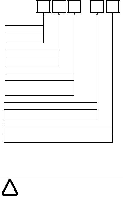
Model Numbering System |
The IMC-S/23x is available as a twoor four-axis motion controller |
|
|
|
with optional Remote I/O Adapter and AxisLink. The complete model |
|
|
number is specified as shown below: |
Pre-Engineered Cable
Assemblies
IMC-S/ 2 3 |
- |
Platform
2 = Stand Alone
Packaging
3 = Compact Package
Number of Axes
2 =Two Axes
4 = Four Axes
Remote I/O Option
R = Remote I/O Adapter
AxisLink Option
L = AxisLink Multi-Axis Synchronization Link
Pre-engineered cable assemblies are used for connecting the Flex I/O, servo amplifiers, feedback devices, axis-specific (dedicated) I/O, and the CPU watchdog. The table below shows the available cable assemblies.
ATTENTION: Do not attempt to make any electrical connections to the IMC-S/23x while the power is on!
! Doing so risks damage to the IMC-S/23x, external components, and your health!
Publication 999-122 - January 1997

Introduction 2-5
|
IMC S/23x Pre-Engineered Cable Assemblies |
|
||
Catalog Number |
Used to Connect. . . |
Length |
|
Number |
|
|
(ft) |
(m) |
Required |
|
|
|
|
|
4100-CCF1 or |
Flex I/O |
1 |
0.3 |
1 per S Class |
4100-CCF3 |
|
3 |
1 |
|
4100-CCS15F |
Servo and Feedback |
15 |
4.5 |
1 per Axis |
4100-CCAQB |
1391B-ES or 1391-DES |
- |
- |
1 per Axis |
4100-CCA15F |
Dedicated Discrete I/O |
15 |
4.5 |
1 per Axis |
4100-CCW15F |
CPU Watchdog |
15 |
4.5 |
1 per S Class |
4100-RCS3T |
REC Interface |
3 |
1 |
1 per Axis |
|
|
|
|
|
Mechanical Specifications |
Front Panel Layout |
|
(IMC-S/23x-RL model shown.) |
Publication 999-122 - January 1997

2-6 Introduction
Mounting and Clearance Dimensions
General Specifications
Motion Control |
|
|
|
Microprocessor |
Intel 80960SB @ 16 MHz. |
|
|
Number of |
2 (Axis 0 and Axis 1) |
IMC-S/232... |
models. |
Controlled Axes |
4 (Axis 0, 1, 2, and 3) |
IMC-S/234... |
models. |
Application |
Write-lockable battery-backed RAM (Random-Access Memory) with 10 |
||
Storage |
year (minimum) battery life for application program (32K) and setup |
||
|
parameter values. |
|
|
Data Storage |
Write-lockable battery-backed RAM (Random-Access Memory) with 10 |
||
|
year (minimum) battery life for cam table and default user variable values. |
||
Number of User |
|
|
|
Variables |
2,000 user-definable; values stored as 64-bit floating-point numbers. |
||
Number of Electronic |
|
|
|
Cam Points |
26,000 total. |
|
|
Publication 999-122 - January 1997
Introduction |
2-7 |
Environmental Specifications
Storage |
-40°C to 70°C (-40°F to 158°F). |
Temperature |
|
Operating |
0°C to 50°C (32°F to 122°F). |
Temperature |
|
Maximum |
|
Humidity |
95% non-condensing. |
Electrical Specifications
AC Power Input |
90 |
- 132 or 175 - 264 Volts AC, |
|
47 |
- 63 Hz, |
|
3 Amperes maximum. |
|
AC Fuse |
3A Dual Element Time Delay (Slow Blow) 1/4 x 11/4 |
|
I/O Power Input |
18 |
- 36V DC, |
|
3A maximum (24V nominal). |
|
I/O Fuse |
3A Dual Element Time Delay (Slow Blow) 1/4 x 11/4 |
|
Encoder Input Specifications
Number of |
2 (Axis 0 and Axis 1) |
IMC-S/232...models. |
Encoder Inputs |
4 (Axis 0, 1, 2, and 3) |
IMC-S/234...models. |
Type of |
Incremental AB quadrature; optically isolated, differential with marker |
|
Encoder Input |
channel. |
|
Encoder |
|
|
Interface IC |
AM26LS32 or equivalent. |
|
Compatible |
Differential, TTL-Level (5V DC) line driver outputs, with or without |
|
Encoder Types |
marker; including the following Allen-Bradley devices: |
|
|
845F-SJxZ14-xxYx... |
|
|
845F-SJxZ24-xxYx... |
|
|
845H-SJxx14xxYx... |
|
|
845H-SJxx24xxYx... |
|
|
845K-SAxZ14-xxY3 |
|
|
845K-SAxZ24-xxY3 |
|
|
845P-SHC14-xx3 |
|
|
845T-xx12Exx... |
|
|
845T-xx13Exx... |
|
|
845T-xx42Exx... |
|
|
845T-xx43Exx... |
|
Decode Modes |
4X Quadrature, Step/Direction, Count Up/Count Down. |
|
Maximum Encoder |
4,000,000 counts per second (4 MHz). This is equivalent to a channel |
|
Frequency |
frequency of 1 MHz in 4X quadrature decode mode. |
|
Input |
7 kΩ minimum (each input). |
|
Impedance |
||
Encoder |
5 or 12 Volts DC at 1 Ampere (total) available from IMC-S/23x. Voltage |
|
Power |
selection by internal switch. |
|
Publication 999-122 - January 1997

2-8 Introduction
Servo Output Specifications
Number of |
2 |
(Axis 0 and Axis 1) |
IMC-S/232...models. |
Servo Drive Outputs |
4 |
(Axis 0, 1, 2, and 3) |
IMC-S/234...models. |
Type of Output Isolated analog voltage or current; individually field-configurable via internal switch for each axis.
Output Range ±10 Volts DC or ±150 μA (minimum).
Resolution 16 bits, 305 μV or 4.58 μA per bit.
Output Impedance 220Ω resistive for voltage output; 56Ω maximum load impedance for current output.
Output Offset ±80 μV maximum. Compensated to 0 volts via software setup procedure.
Dedicated Discrete I/O
Specifications
Number of |
|
|
Dedicated Discrete |
10 (5 each for Axis 0 and 1) |
IMC-S/232...models. |
Inputs |
20 (5 each for Axis 0, 1, 2, and 3) |
IMC-S/234...models |
Dedicated |
Home Limit Switch, |
|
Discrete Input |
Positive Overtravel Limit Switch, |
|
Functions |
Negative Overtravel Limit Switch, |
|
|
Drive (Amplifier) Fault, |
|
|
Position Registration. |
|
Input Type |
Optically isolated. |
|
Operating |
24 Volts DC nominal; 28V DC maximum. |
|
Voltage |
24 Volts DC nominal; 28V DC maximum or 5 Volts DC nominal; |
|
|
10V DC maximum for position registration inputs. |
|
Input ON |
12 μΑ per input (nominal); |
|
Current |
2.5 μΑ for position registration inputs. |
|
Input |
2 kΩ (resistive) per input; |
|
Impedance |
8.8 kΩ (resistive) for 24V position registration inputs. |
|
Input Response |
5 μs maximum; |
|
Time |
1 μs maximum for position registration inputs. |
|
Number of |
|
|
Dedicated |
4 (2 each for Axis 0 and 1)IMC-S/232...models. |
|
Discrete Outputs |
8 (2 each for Axis 0, 1, 2, and 3)IMC-S/234...models. |
|
Dedicated Discrete |
Drive (Amplifier) Enable. |
|
Output Function |
Absolute Position Strobe. |
|
Output Type |
Normally-open relay contacts (Drive Enable); |
|
|
Optically isolated, floating, solid-state relay (Position Strobe). |
|
Operating |
0.010 - 40 Volts DC; 24V DC nominal for drive enable outputs, |
|
Voltage |
5.10± 0.10 Volts DC for position strobe outputs. |
|
Output |
1 Ampere per output maximum for drive enable outputs; |
|
Current |
10 μΑ per output maximum for position strobe outputs. |
|
Publication 999-122 - January 1997
Introduction |
2-9 |
Serial I/O Specifications
Number of |
|
Serial Channels |
2 (Serial Port A and Serial Port B). |
Channel Type |
Optically isolated RS-232C or RS-422; each channel individually |
|
configurable via internal switch. |
Information Code |
ASCII (American Standard Code for Information Interchange). |
Baud Rate |
User-selectable up to 128k Baud (RS-422). |
|
User-selectable up to 115.2k Baud (RS-232C). |
Number of |
|
Start Bits |
1. |
Number of |
|
Stop Bits |
1. |
Word Length |
8 bits total; 7 data bits plus 1 parity bit. |
Parity |
Space parity transmitted; |
|
Receive parity ignored (may be Mark, Space, Even, or Odd). |
Duplex |
Full or half (user-selectable). |
Data |
|
Synchronization |
XON (Control-Q)/XOFF (Control-S). |
Front-Panel |
|
Connectors |
IBM-PC/AT compatible 9-pin D-type female. |
RS-422 |
User-selectable 220Ω resistor via internal switch. |
Termination |
DH-485 Specifications
Number of |
|
|
DH-485 Channels |
1; replaces Serial port B when used. |
|
Channel Type |
Optically isolated half-duplex RS-485. |
|
Baud Rate |
9,600 or 19.2k Baud (user-selectable). |
|
Front-Panel |
|
|
Connectors |
Two RJ-45 jacks (+24V is not provided). |
|
RS-485 |
User-selectable 220Ω resistor via internal switch. |
|
Termination |
||
Node Address |
User-selectable between 0 and 31 inclusive. |
|
Node Type |
Token-passing master. |
|
Accessible Data |
1 |
Binary file (B3) for up to 16,384 bits |
Files |
1 |
Integer file (N7) for up to 1,024 16-bit values |
|
1 |
Floating-point file (F8) for up to 512 32-bit values |
|
1 |
ASCII string file (A) for up to 2,048 characters |
9 user-configurable files; each can be individually configured as any of the above types or as a BCD file for floating point simulation (required for certain A-B MMI devices).
Publication 999-122 - January 1997

2-10 Introduction
Flex I/O Compatibility
Specifications
Maximum Number of |
|
|
|
|
Flex I/O Modules |
8. |
|
|
|
Compatible |
1794-IB16 |
16 24V |
DC Discrete Inputs |
|
Modules |
1794-IA8 |
8 |
115V |
AC Discrete Inputs |
|
1794-IE8 |
8 |
Current/Voltage Analog Inputs |
|
|
1794-OB16 |
16 24V |
DC Discrete Outputs |
|
|
1794-OA8 |
8 |
115V |
AC Discrete Outputs |
|
1794-OE4 |
4 |
Current/Voltage Analog Outputs |
|
|
1794-IE4XOE2 |
4 |
Current/Voltage Analog Inputs |
|
|
|
2 |
Current/Voltage Analog Outputs |
|
S Class Interface |
Direct-no 1794-ASB or other adapter required. |
|||
Servo Performance
Specifications
Servo Loop |
|
Sample and Update |
|
Rate |
250 Hz to 2 kHz for each of 2 or 4 axes. |
Maximum Feedback |
|
Frequency |
4 MHz (4,000,000 feedback counts per second). |
Absolute |
± 1,000,000,000 feedback counts for Linear AxisAxis:Linearlinear axes; |
Position Range |
R for rotary axes. |
Absolute Position |
15 position unit digits or |
Resolution |
32 feedback count bits, whichever is less. |
Speed Range |
0.00001 feedback counts per servo update to 4,000,000 feedback counts |
|
per second. |
Speed Resolution |
15 position unit digits or |
|
15 feedback count bits, whichever is less. |
Acceleration/ |
0.00001 feedback counts per servo update2 to 4,000,000,000 feedback |
Deceleration Range |
counts per second2. |
Acceleration/Deceleration |
15 position unit digits or |
Resolution |
15 feedback count bits, whichever is less. |
Electronic Gearing |
|
Gear Ratio Range |
0.00001:1 to 9.99999:1 (slave counts : master counts). |
Electronic Gearing |
|
Gear Ratio Resolution |
8 position unit digits or 32 feedback count bits. |
Servo Gain Resolution |
32 bit floating point. |
Servo Output Limit |
|
Range |
0 to 100%. |
Servo Output Limit |
305 μ (voltage output); 4.58μΑ (current output). |
Resolution |
Publication 999-122 - January 1997

Introduction |
2-11 |
Servo Gain Units
|
|
|
IMC-S/23x Servo Gain Units |
||
|
Gain |
|
Description |
|
Units |
|
|
|
|||
|
|
|
|
|
|
|
P |
|
Proportional Gain |
|
Counts per Millisecond |
|
|
|
|
|
Count of Error |
|
I |
|
Integral Gain |
|
Counts per Millisecond2 |
|
|
|
|
|
Count of Error |
|
V |
|
Velocity Gain |
|
Millivolts |
|
|
|
|
|
Count per Millisecond |
|
F |
|
Feedforward Gain |
|
Counts per Millisecond |
|
|
|
|
|
Count per Millisecond |
|
|
|
Deadband Compensation |
|
Volts |
|
|
|
Offset Compensation |
|
Volts |
Remote I/O Adapter |
|
|
|
|
|
IMC-S/23x-R and IMC-S/23x-RL models only. |
|||||
Specifications |
|
|
|
|
|
Baud Rate 57.6K, 115.2K or 230.4K (User-selectable).
Rack Address User-selectable between 0 and 31 decimal.
Rack Width User-selectable in quarter-rack increments (1/4, 1/2, 3/4, Full).
I/O Group Address User selectable as shown below:
IMC-S/23x Remote I/O Adapter Addressing
Type of Transfer |
|
|
|
|
I/O Group |
|
|
|
||
|
|
|
|
|
|
|
|
|
|
|
Block |
0 |
2 |
4 |
6 |
0 |
2 |
4 |
0 |
2 |
0 |
Discrete |
1 |
3 |
5 |
7 |
1 |
3 |
5 |
1 |
3 |
1 |
Discrete |
|
|
|
|
2 |
4 |
6 |
2 |
4 |
2 |
Discrete |
|
|
|
|
3 |
5 |
7 |
3 |
5 |
3 |
Discrete |
|
|
|
|
|
|
|
4 |
6 |
4 |
Discrete |
|
|
|
|
|
|
|
5 |
7 |
5 |
Discrete |
|
|
|
|
|
|
|
|
|
6 |
Discrete |
|
|
|
|
|
|
|
|
|
7 |
|
|
|
|
|
|
|
|
|
|
|
Starting I/O Group |
0 |
2 |
4 |
6 |
0 |
2 |
4 |
0 |
2 |
0 |
|
|
|
|
|
|
|
|
|
|
|
Rack Width |
|
|
1/4 |
|
|
1/2 |
|
|
3/4 |
Full |
|
|
|
|
|
|
|
|
|
|
|
Publication 999-122 - January 1997

2-12 Introduction
Number of |
12 dedicated inputs, |
|
|
|
||
Discrete I/O Bits |
12 dedicated outputs, |
|
|
|
||
|
User-defined as shown below: |
|
||||
|
|
|
|
|||
|
|
IMC-S/23x Remote I/O Adapter |
|
|||
|
|
Number of User-Defined Discrete I/O Bits |
||||
|
|
|
|
|
|
|
|
|
Rack Width |
|
Inputs |
|
Outputs |
|
|
|
|
|
|
|
|
1/4 |
|
4 |
|
4 |
|
|
1/2 |
|
36 |
|
36 |
|
|
3/4 |
|
68 |
|
68 |
|
|
|
Full |
|
100 |
|
100 |
Maximum Block |
|
|
|
|
|
|
|
|
|
|
|
|
|
Transfer Length |
64 words (128 bytes). |
|
|
|
||
Block Transfer |
User Variable values, |
|
|
|
||
Data Types |
Axis Data Parameter value, |
|
||||
|
Axis Data Bit state, |
|
|
|
||
|
Master Cam Position Point values, |
|
||||
|
Master Cam Time Point values, |
|
||||
|
Slave Cam Position Point values, |
|
||||
|
Axis or System Variable value. |
|
||||
Block Transfer |
32-bit (double-word) 2s complement integer, |
|||||
Data Formats |
16-bit (single-word) 2s complement integer, |
|||||
|
32-bit (8-digit) signed BCD, |
|
||||
|
32-bit IEEE floating-point, |
|
||||
Word-swapped 32-bit (double-word) 2s complement integer,
Word-swapped 32-bit (8-digit) signed BCD,
Word-swapped 32-bit IEEE floating-point.
Publication 999-122 - January 1997
Introduction |
2-13 |
AxisLink Specifications |
IMC-S/23x-L and IMC-S/23x-RL models only. |
||
Baud Rate |
Standard and extended |
1 megabit per second. |
|
|
node configurations |
|
|
|
Extended length |
500 kilobit per second. |
|
|
configuration |
|
|
Cable Type |
Standard and extended |
Allen-Bradley 1770-CD RIO cable (Belden 9463 or |
|
|
node configurations |
equivalent). |
|
|
Extended length |
Belden 9182, Carol C8014 or equivalent. |
|
|
configuration |
|
|
Cable Length |
Standard and extended |
25 meters (82 feet) maximum total. Minimum of 1 |
|
|
node configurations |
meter (3 feet) between controllers. |
|
|
Extended length |
125 meters (410 feet) maximum total. Minimum of 1 |
|
|
configuration |
meter (3 feet) between controllers. |
|
Number of |
Standard and extended |
8 maximum for a total of 32 possible axes. |
|
Motion Controllers |
length configurations |
|
|
|
Extended node |
16 maximum for a total of 64 possible axes. |
|
|
configuration |
|
|
Addressing |
Standard and extended |
User-selectable address via rotary selector switch on |
|
|
length configurations |
front panel. |
|
|
Extended node |
User-selectable address via GML. |
|
|
configuration |
|
|
Number of Virtual |
Standard configuration |
Master Axes |
|
Extended length and extended node configurations
4 maximum total; 1 per motion controller maximum.
Any axis on any motion controller can be a virtual master axis to any other motion controller. Each motion controller can define a total of two separate axes on any other motion controllers as virtual master axes, but only one can be active at any time. A total of four different axes can be active as virtual master axes at any time.
2 maximum total; 1 per motion controller maximum.
Any axis on any motion controller can be a virtual master axis to any other motion controller. Each motion controller can define a total of two separate axes on any other motion controllers as virtual master axes, but only one can be active at any time. A total of two different axes can be active as virtual master axes at any time.
Type of Virtual |
All configurations |
2: Command and Actual. Each virtual master axis may |
Master Axes |
|
be defined to report its command or actual position. |
Slave Axes |
Standard and extended |
31 maximum total per virtual master axis (3 local + 4 |
|
length configurations |
x 7 other motion controllers = 31). |
|
Extended node |
63 maximum total per virtual master axis (3 local + 4 |
|
configuration |
x 15 other motion controllers = 63). |
Publication 999-122 - January 1997

2-14 Introduction
Number of |
All configurations |
112 inputs maximum total and 16 user-definable |
Discrete I/O |
|
outputs per motion controller. Any motion controller |
|
|
can read the 16 discrete outputs of any other motion |
|
|
controller, giving a maximum total of 7 x 16 = 112 |
|
|
discrete inputs per motion controller. For extended |
|
|
node configuration, discrete I/O can still only be |
|
|
obtained from a maximum of 7 other controllers (112 |
|
|
inputs maximum total), not from all 15 other controllers |
|
|
available in a 16 node maximum extended node |
|
|
configuration. |
Discrete I/O |
All configurations |
≤1 millisecond. |
Response |
|
|
Publication 999-122 - January 1997
 Loading...