


 Loading...
Installation Instructions
InView Ethernet TCP/IP Module
(Catalog Number 2706-PENET1)
Inside . . . |
|
English ................................................................................................................................ |
3 |
Français ............................................................................................................................ |
13 |
Deutsch ............................................................................................................................ |
23 |
Italiano ............................................................................................................................. |
33 |
Español ............................................................................................................................. |
43 |
Português ......................................................................................................................... |
53 |
Publication 2706-IN008D-MU-P - October 2003

2 InView Ethernet TCP/IP Module
Publication 2706-IN008D-MU-P - October 2003

Installation Instructions
InView Ethernet TCP/IP Module
(Catalog Number 2706-PENET1)
English
Inside . . . |
|
Overview ............................................................................................................................ |
4 |
Why Use the InView Ethernet TCP/IP Module? ................................................................. |
4 |
Description of the InView Ethernet TCP/IP Module .......................................................... |
4 |
Wiring the Ethernet TCP/IP Module to the InView Display .............................................. |
5 |
Mounting Module to the P42, P43 and P44 Displays ........................................................ |
7 |
Mounting Module to the P72 and P74 Displays ................................................................ |
8 |
Setting the IP Address ....................................................................................................... |
8 |
Publication 2706-IN008D-EN-P - October 2003
4 InView Ethernet TCP/IP Module
Overview
A serial server is an electronic device that provides Ethernet connections for signs and other serial devices by converting serial data to and from Ethernet format.
A serial server is an economical way to add InView Displays to an existing LAN. Instead of running separate cabling to create a sign network, InView displays can be attached to an existing Ethernet LAN using serial servers. This allows you to use the InView ActiveX control for triggering messages and updating variables from RSView32 or other ActiveX containers.
Why Use the InView Ethernet TCP/IP Module?
The serial server connects devices directly to the Ethernet network, which conserves physical ports on the host, allows the terminal to access more than one host, and simplifies terminal cabling.
The InView Ethernet TCP/IP module comes with serial cabling and a NEMA Type 4x enclosure to connect your InView Display to Ethernet.
Description of the InView Ethernet TCP/IP Module
The primary component of the InView Ethernet TCP/IP module is the Lantronix MSS Lite B Ethernet to serial converter.
DB25 serial port


Ethernet Adapter
LED diagnostic lights:
 1. ACT (activity)

 2. LNK (network link connection)
 3. PWR (power)
RJ45 Ethernet port
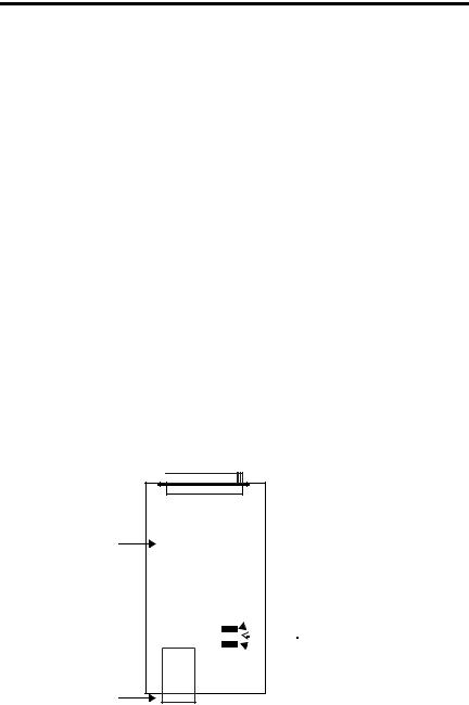
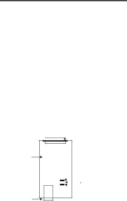
Below is a picture and description of the InView Ethernet TCP/IP module and its connectors with relation to an InView Display.
Publication 2706-IN008D-EN-P - October 2003

InView Ethernet TCP/IP Module 5
Back of InView Display (P42, P43, P44)
Customer-supplied Ethernet through NEMA-rated supplied connector  Note: Loop Ethernet
cable inside enclosure to relieve stress on the communication card.
2706-PENET1
NEMA Type 4X Enclosure with Removable Cover Torque Enclosure Cover screws to 1.1 Nm (10.0 in-lb).
 To terminal block
 inside power supply cover
  on back of display
Serial cable to be connected to InView display
Wiring the Ethernet TCP/IP Module to the InView Display
1. Disconnect power to InView display.
ATTENTION |
Hazardous voltage. Contact with high voltage may |
|||
cause death or serious injury. Always disconnect power |
||||
|
|
|
||
|
|
|
to sign prior to servicing. |
|
|
|
|
|
|
|
|
|
|
|
|
|
|
|
|
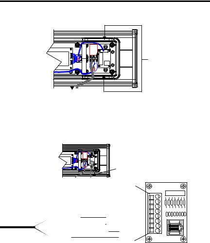
2.Remove the power supply cover by unscrewing its 6 screws. Set the screws and cover aside for later step.

 Right conduit openings
3.Feed the serial cable through the cable grip (shipped with module).
4.Insert the serial wires through the right conduit opening on either the top or the bottom of the InView display.
Publication 2706-IN008D-EN-P - October 2003

6 InView Ethernet TCP/IP Module
TB1 Terminal Block for serial connection
Insert the serial wires with the cable grip into one of these conduit openings.
Power Line 
5.Mount the cable grip to the InView display housing. Tighten the locknut finger-tight and rotate an additional 1/2 turn.
6.Connect the incoming serial wires to the TB1 terminal block.
|
TB1 |
|
Incoming serial wires |
|
TB1 Terminal Block |
|
(NC) 8 |
|
(NC) 7 |
|
(NC) 6 |
|
(NC) 5 |
White (Rxd) |
(RS-232 RX) 4 |
White / Black Line (Txd) |
(RS-232 TX) 3 |
Black / White Line (PWR) |
(+5V) 2 |
Black (GND) |
(GND) 1 |
|
TIP |
Be sure to place the wires so they are not caught by screws |
|
when replacing the power supply cover, and also so they do |
||
|
||
|
not interfere with fan operation. |
7.Torque the cable grip until the cap is completely seated.
8.Replace the power supply back cover with the 6 screws. Torque the screws to 2.7Nm (24 in-lbs).
9.Connect the power supply to a power source.
Publication 2706-IN008D-EN-P - October 2003

InView Ethernet TCP/IP Module 7
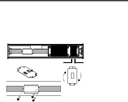
Mounting Module to the P42, P43 and P44 Displays
The InView Ethernet TCP/IP module is designed to mount to the track of the InView P42, P43 and P44 displays. The back plate of the module has tabs for attaching to the track. Tighten mounting screws until they bottom out against the back plate.
Power Line
 Back Plate
with Tabs
Serial Cable
For ease in mounting, rotate module 90° so that the mounting holes are on top and bottom. Rotate the module clockwise over track until the alignment is horizontal.
Publication 2706-IN008D-EN-P - October 2003
8 InView Ethernet TCP/IP Module
Mounting Module to the P72 and P74 Displays
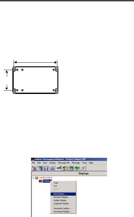
The P72 and P74 InView displays do not have a track for mounting the module on the display. You can remove the back plate and mount the bottom of the enclosure to a wall or panel near the display. Use screws (8-32 UNC-2A) measuring a minimum of 1/4” plus the thickness of the mounting surface.
The dimensions for the 4 mounting holes are shown below.
Enclosure Case
7.40 in (188 mm)
3.46
(88 mm)
Setting the IP Address
The Ethernet TCP/IP configuration utility is installed as part of the Inview Messaging Software package. When first opening the Inview Messaging Software, you are asked to create a display and a message file. After the display is created you can configure the IP address of the 2706-PENET1 module.
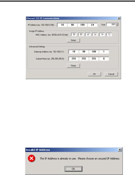
1.Select the display you created, which will use the Ethernet module. Right click on the display and select Edit Display as shown below.
Publication 2706-IN008D-EN-P - October 2003

InView Ethernet TCP/IP Module 9
TIP |
Double-clicking on the display will take you to the same |
|
window. |
||
|
2.When the Edit Display window appears, go to the Communications tab. This is where the configuration utility is located.
3.Under the section with the heading TCP/IP settings is the Configure Communications button. By clicking this button you will be taken to the Ethernet TCP/IP Communications window. This is where the IP address will be set.
Publication 2706-IN008D-EN-P - October 2003
10 InView Ethernet TCP/IP Module
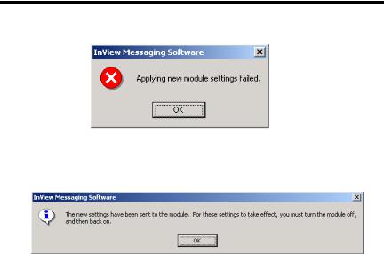
4.At the top of the window labeled IP Address, this is where you would put in the desired IP address. The Port, if using a 2706-PENET1 module should be 3001. Under the heading Assign IP Address, this is where you would enter the MAC Address of the module. The MAC Address will be found on the module itself.
5.Once the desired IP Address, Port, and MAC Address have been entered, click the Setup button located in the section titled Assign IP Address.
If the IP Address is already in use, an error message window will appear, like the one shown below.
TIP |
If the above window appears, just click OK and choose a |
|
different desired IP Address and click the Setup button again. |
||
|
||
|
Once a valid IP Address has been entered the following |
|
|
window should appear saying it is ready to assign an IP |
|
|
address. |
Publication 2706-IN008D-EN-P - October 2003
InView Ethernet TCP/IP Module 11
6.As the message instructs, you will need to either turn the display on or power cycle the display if it is already turned on. Upon successfully assigning an IP Address the following window will appear.
Gateway Address and Subnet Mask Setup
Next, is to setup the desired Gateway Address and Subnet Mask, if needed.
Subnet Mask - This parameter interprets IP addresses when the network is divided into multiple networks. The IP address is formatted as four sets of decimal numbers with periods between them (255.255.255.1). The range of values for the first set of decimal numbers is 1 to 255. The range of values for the last three sets of decimal numbers is 0 to 255. The value 0.0.0.0 is not a valid subnet mask.
Gateway Address - A unique address of the Gateway connecting two individual IP networks into a system of networks. When a node needs to communicate with a node on another network, the Gateway transfers the data between the two networks. The IP address is formatted as four sets of decimal numbers (from 1 to 255) with periods between them (130.0.0.1). The first field cannot be 0 if any other fields contain a 0.
Once the desired Gateway Address and Subnet Mask have been entered, click on the Setup button located just below where the Subnet Mask was entered. If for some reason, the settings are not received by the 2706-PENET1 module, the following error message will appear.
Publication 2706-IN008D-EN-P - October 2003
12 InView Ethernet TCP/IP Module
However, upon successfully setting up the Gateway Address and Subnet Mask, the following message will appear telling you to cycle power to the module.
After the IP Address, Gateway Address and Subnet Mask have all been established, click the OK button on the bottom of the Ethernet TCP/IP Communications window. This will allow the settings to be saved and configuration is now complete.
Once the settings have been saved, they can now be viewed, by clicking on the Advanced button located in the section titled TCP/IP settings on the Edit Display window.
Publication 2706-IN008D-EN-P - October 2003

Notice d’installation
Module Ethernet TCP/IP InView
(Référence 2706-PENET1)
Français
Sommaire... |
|
Présentation ..................................................................................................................... |
14 |
Pourquoi utiliser le module Ethernet TCP/IP InView ? ..................................................... |
14 |
Description du module Ethernet TCP/IP InView .............................................................. |
14 |
Câblage du module Ethernet TCP/IP InView à l’afficheur InView ................................... |
15 |
Montage du module sur les afficheurs P42, P43 et P44 ................................................. |
17 |
Montage du module sur les afficheurs P72 et P74 ......................................................... |
18 |
Définition de l’adresse IP ................................................................................................. |
18 |
Publication 2706-IN008D-MU-P - Octobre 2003
14 Module Ethernet TCP/IP InView
Présentation
Un serveur en série est un appareil électronique qui fournit des connexions Ethernet pour les périphériques de signaux et autres périphériques en série, en convertissant les données série au format Ethernet et inversement.
Un serveur en série constitue un moyen économique pour ajouter des afficheurs InView à un réseau local existant. Plutôt que de réaliser des câblages séparés pour créer un réseau de signaux, les afficheurs InView peuvent être raccordés à un réseau local Ethernet existant à l’aide de serveurs en série. Vous pouvez ainsi utiliser le contrôle ActiveX InView pour déclencher des messages et mettre à jour des variables à partir de RSView32 ou d’autres conteneurs ActiveX.
Pourquoi utiliser le module Ethernet TCP/IP InView ?
Un serveur en série connecte des équipements directement au réseau Ethernet, qui conserve les ports physiques sur l’hôte, permet au terminal d’accéder à plusieurs hôtes et en simplifie le câblage.
Le module Ethernet TCP/IP InView est fourni avec des câbles série et un boîtier NEMA Type 4x pour la connexion de l’afficheur InView à Ethernet.
Description du module Ethernet TCP/IP InView
Le principal composant du module Ethernet TCP/IP InView est le convertisseur Ethernet/série Lantronix MSS Lite B.
Port série DB25 


Adaptateur Ethernet
Voyants de diagnostic :
 1. ACT (activité)

 2. LNK (connexion réseau)
 3. PWR (alimentation)
Port Ethernet RJ45
Publication 2706-IN008D-MU-P - Octobre 2003

Module Ethernet TCP/IP InView 15
Vous trouverez ci-dessous une représentation et une description du module Ethernet TCP/IP InView et de ses connecteurs associés à un afficheur InView.
Arrière de l’afficheur InView (P42, P43, P44)
Connexion du câble Ethernet fourni par le client par le connecteur NEMA fourni Remarque : enroulez le
câble Ethernet à l’intérieur du boîtier pour éviter qu’il n’appuie sur la carte de communication.
2706-PENET1
Boîtier NEMA Type 4X avec capot amovible
Serrez les vis maintenant le capot du boîtier avec un couple de 1,1 Nm
Vers le bornier situé à  l’intérieur du capot
 de l’alimentation à l’arrière
  de l’afficheur
Câble série à connecter à l’afficheur InView
Câblage du module Ethernet TCP/IP InView à l’afficheur InView
1. Coupez l’alimentation de l’afficheur InView.
ATTENTION |
Tension dangereuse. Tout contact avec une tension |
|||
élevée peut entraîner des blessures graves voire |
||||
|
|
|
||
|
|
|
mortelles. Coupez toujours l’alimentation de l’afficheur |
|
|
|
|
avant d’effectuer une opération de maintenance. |
|
|
|
|
|
|
|
|
|
|
|
|
|
|
|
|
2.Retirez le capot de l’alimentation en dévissant les six vis. Mettez les vis et le couvercle de côté : vous les réutiliserez plus tard.

 Ouvertures de conduit à droite
3.Passez le câble série dans le serre-câble (fourni avec le module).
4.Insérez les câbles série par le conduit supérieur ou inférieur droit de l’afficheur InView.
Publication 2706-IN008D-MU-P - Octobre 2003
16 Module Ethernet TCP/IP InView
Bornier TB1 pour la connexion série
Insérez le câble série avec le serre-câble dans l’une des ouvertures de conduit.
Ligne d’alimentation
5.Montez le serre-câble sur le boîtier de l’afficheur InView. Serrez l’écrou à la main et effectuez un demi tour supplémentaire.
6.Connectez les câbles série entrants au bornier TB1.
 TB1
TB1
|
Câbles série entrants |
|
Bornier TB1 |
|
(NC) 8 |
|
(NC) 7 |
|
(NC) 6 |
|
(NC) 5 |
Blanc (Réception) |
(RS-232 RX) 4 |
Blanc/Bande noire (Emission) |
(RS-232 TX) 3 |
Noir/Bande blanche (Alimentation) |
(+5V) 2 |
Noir (Terre) |
(GND) 1 |
|
CONSEIL |
Veillez à positionner les câbles de façon à ce qu’ils ne se |
|
coincent pas dans les vis lorsque vous remettrez le capot de |
||
|
||
|
l’alimentation en place et pour qu’ils n’empêchent pas le bon |
|
|
fonctionnement du ventilateur. |
7.Tournez le serre-câble jusqu’à ce que le capot soit bien en place.
8.Remettez le capot de l’alimentation en place à l’aide des six vis. Serrez les vis avec un couple de 2,7 Nm.
9.Connectez le câble d’alimentation à une source d’alimentation.
Publication 2706-IN008D-MU-P - Octobre 2003
Module Ethernet TCP/IP InView 17
Montage du module sur les afficheurs P42, P43 et P44
Le module Ethernet TCP/IP InView est conçu pour être monté sur la glissière des afficheurs InView P42, P43 et P44. Les pattes situées sur la plaque de montage du module permettent de le fixer sur la glissière. Serrez les vis jusqu’à ce qu’elles soient en contact avec la plaque de montage.
Ligne d’alimentation
 Plaque de montage avec pattes
Câble série
Pour faciliter le montage, faites pivoter le module de 90° afin que les trous de fixation soient en haut et en bas. Faites pivoter le module sur la glissière dans le sens des aiguilles d’une montre, jusqu’à ce que l’alignement soit horizontal.
Publication 2706-IN008D-MU-P - Octobre 2003

18 Module Ethernet TCP/IP InView
Montage du module sur les afficheurs P72 et P74
Les afficheurs InView P72 et P74 ne comportent pas de glissière pour le montage du module. Vous avez la possibilité de retirer la plaque de montage et d’assembler la partie inférieure du boîtier sur un mur ou un panneau situé près de l’afficheur. Utilisez des vis (8-32 UNC-2A) d’au moins 6,5 mm, plus l’épaisseur de la surface de montage.
Les dimensions pour les quatre trous de fixation sont indiquées ci-dessous.
Boîtier
188 mm
88 mm
Définition de l’adresse IP
L’utilitaire de configuration Ethernet TCP/IP est installé en même temps que l’ensemble logiciel Inview Messaging. Lorsque vous lancez le logiciel Inview Messaging pour la première fois, il vous est demandé de créer un écran et un fichier de messages. Dès que l’écran est créé, vous pouvez configurer l’adresse IP du module 2706-PENET1.
1.Sélectionnez l’écran que vous avez créé et qui utilisera le module Ethernet. Cliquez sur l’écran avec le bouton droit de la souris et sélectionnez Edit Display (Editer l’écran) comme indiqué ci-dessous.
Publication 2706-IN008D-MU-P - Octobre 2003

Module Ethernet TCP/IP InView 19
CONSEIL |
Vous accéderez à la même fenêtre en cliquant deux fois sur |
|
l’écran. |
||
|
2.Quand la fenêtre d’édition d’écran apparaît, cliquez sur l’onglet Communications : vous y trouverez l’utilitaire de configuration.
3.La section intitulée TCP/IP Settings (Réglages TCP/IP) contient le bouton Configure Communications (Configurer les communications). En cliquant sur ce bouton, vous accédez à la fenêtre de communication Ethernet TCP/IP. C’est là que vous allez définir l’adresse IP.
Publication 2706-IN008D-MU-P - Octobre 2003

20 Module Ethernet TCP/IP InView
4.Entrez l’adresse IP souhaitée dans la partie supérieure de la fenêtre, intitulée IP Address. Si vous utilisez un module 2706-PENET1, le Port doit être 3001. Dans la section Assign IP Address (Attribuer l’adresse IP), entrez l’adresse MAC (MAC Address) du module. L’adresse MAC est indiquée sur le module même.
5.Une fois que vous avez saisi l’adresse IP, le port et l’adresse MAC, cliquez sur le bouton Setup (Configurer) situé dans la section Assign IP Address (Attribuer l’adresse IP).
Si l’adresse IP est déjà utilisée, un message d’erreur, comme celui ci-dessous, apparaît.
CONSEIL |
Si le message ci-dessus apparaît, cliquez sur OK, choisissez |
|
une autre adresse IP, puis cliquez de nouveau sur le bouton |
||
|
||
|
Setup. Une fois que vous avez saisi une adresse IP correcte, le |
|
|
message suivant devrait apparaître, indiquant que le logiciel |
|
|
est prêt à attribuer l’adresse IP. |
Publication 2706-IN008D-MU-P - Octobre 2003
Loading...