


Stack Light
Bulletin 855T
User Manual
Important User Information
Because of the variety of uses for the products described in this publication, those responsible for the application and use of this control equipment must satisfy themselves that all necessary steps have been taken to assure that each application and use meets all performance and safety requirements, including any applicable laws, regulations, codes and standards.
The illustrations, charts, sample programs and layout examples shown in this guide are intended solely for purposes of example. Since there are many variables and requirements associated with any particular installation, Allen-Bradley does not assume responsibility or liability (to include intellectual property liability) for actual use based upon the examples shown in this publication.
Allen-Bradley publication SGI-1.1, Safety Guidelines for the Application, Installation and Maintenance of Solid-State Control (available from your local Allen-Bradley office), describes some important differences between solid-state equipment and electromechanical devices that should be taken into consideration when applying products such as those described in this publication.
Reproduction of the contents of this copyrighted publication, in whole or part, without written permission of Rockwell Automation, is prohibited.

Throughout this manual we use notes to make you aware of safety considerations:
|
Identifies information about practices or circumstances that can lead |
|
ATTENTION |
||
to personal injury or death, property damage or economic loss |
||
|
!
Attention statements help you to:
•identify a hazard
•avoid a hazard
•recognize the consequences
|
Identifies information that is critical for successful application and |
|
IMPORTANT |
||
understanding of the product. |
||
|
||
|
Allen-Bradley is a trademark of Rockwell Automation
DeviceNet is a trademark of the Open DeviceNet Vendor Association (ODVA).
European Communities (EC) Directive Compliance
If this product has the CE mark it is approved for installation within the European Union and EEA regions. It has been designed and tested to meet the following directives.
EMC Directive
This product is tested to meet the Council Directive 89/336/EC Electromagnetic Compatibility (EMC) by applying the following standards, in whole or in part, documented in a technical construction file:
•EN 50081-2 EMC — Generic Emission Standard, Part 2 — Industrial Environment
•EN 50082-2 EMC — Generic Immunity Standard, Part 2 — Industrial Environment This product is intended for use in an industrial environment.
Low Voltage Directive
This product is not required to meet Council Directive 73/23/EEC Low Voltage, as it is designed for use with a voltage rating below 50V for alternating current and below 75V for direct current. The requirements of EN 60947-5-1:1997 Low-Voltage Switchgear and Controlgear, Part 5 - Control Circuit Devices, have been applied.

Table of Contents
Preface
Intended Audience . . . . . . . . . . . . . . . . . . . . . . . . . . . . . . . . . . . . . . . . i Contents of Manual . . . . . . . . . . . . . . . . . . . . . . . . . . . . . . . . . . . . . . . i Related Publications . . . . . . . . . . . . . . . . . . . . . . . . . . . . . . . . . . . . . . . ii EDS Web Site . . . . . . . . . . . . . . . . . . . . . . . . . . . . . . . . . . . . . . . . . . . . ii
Chapter 1 — Overview of DeviceNet Stack Light
Chapter Objectives . . . . . . . . . . . . . . . . . . . . . . . . . . . . . . . . . . . . . . 1-1
Description . . . . . . . . . . . . . . . . . . . . . . . . . . . . . . . . . . . . . . . . . . . . 1-1
Base Features. . . . . . . . . . . . . . . . . . . . . . . . . . . . . . . . . . . . . . . . . . . 1-2
Module Positions . . . . . . . . . . . . . . . . . . . . . . . . . . . . . . . . . . . . . . . 1-3
Rotary Switches. . . . . . . . . . . . . . . . . . . . . . . . . . . . . . . . . . . . . . . . . 1-3
DeviceNet Connection. . . . . . . . . . . . . . . . . . . . . . . . . . . . . . . . . . . 1-3
Typical DeviceNet Configuration . . . . . . . . . . . . . . . . . . . . . . . . . . 1-4
DeviceNet Components. . . . . . . . . . . . . . . . . . . . . . . . . . . . . . . . . . 1-5
Replacement Parts. . . . . . . . . . . . . . . . . . . . . . . . . . . . . . . . . . . . . . . 1-5
Chapter 2 — Quick Start
Chapter Objectives . . . . . . . . . . . . . . . . . . . . . . . . . . . . . . . . . . . . . . 2-1 Data Rate Configuration. . . . . . . . . . . . . . . . . . . . . . . . . . . . . . . . . . 2-1 Node Address Configuration . . . . . . . . . . . . . . . . . . . . . . . . . . . . . . 2-2 Installing the Modules . . . . . . . . . . . . . . . . . . . . . . . . . . . . . . . . . . . 2-2 Connection to the Network . . . . . . . . . . . . . . . . . . . . . . . . . . . . . . . 2-2 Stack Light Parameter Configuration. . . . . . . . . . . . . . . . . . . . . . . . 2-3 Scanner Configuration . . . . . . . . . . . . . . . . . . . . . . . . . . . . . . . . . . . .2-6
Chapter 3 — Installation and Mounting
Chapter Objectives . . . . . . . . . . . . . . . . . . . . . . . . . . . . . . . . . . . . . . 3-1
DeviceNet Guidelines. . . . . . . . . . . . . . . . . . . . . . . . . . . . . . . . . . . . 3-1
Equipment Needed. . . . . . . . . . . . . . . . . . . . . . . . . . . . . . . . . . . . . . 3-1
Setting the Rotary Switches . . . . . . . . . . . . . . . . . . . . . . . . . . . . . . . 3-1
DeviceNet Stack Light Base Dimensions . . . . . . . . . . . . . . . . . . . . 3-4
Mounting the DeviceNet Stack Light . . . . . . . . . . . . . . . . . . . . . . . 3-5
Publication 855T-UM001C-EN-P May 2005

Table of Contents
Chapter 4 — Operations
Chapter Objectives . . . . . . . . . . . . . . . . . . . . . . . . . . . . . . . . . . . . . . 4-1
Parameter Configuration . . . . . . . . . . . . . . . . . . . . . . . . . . . . . . . . . . 4-1
I/O Configuration. . . . . . . . . . . . . . . . . . . . . . . . . . . . . . . . . . . . . . . 4-7
Resetting the Device . . . . . . . . . . . . . . . . . . . . . . . . . . . . . . . . . . . . . 4-8
DeviceNet Operations. . . . . . . . . . . . . . . . . . . . . . . . . . . . . . . . . . . . 4-8
Chapter 5 — Troubleshooting and Maintenance
Chapter Objectives . . . . . . . . . . . . . . . . . . . . . . . . . . . . . . . . . . . . . . 5-1
Preventive Maintenance . . . . . . . . . . . . . . . . . . . . . . . . . . . . . . . . . . 5-1
LED Indicators . . . . . . . . . . . . . . . . . . . . . . . . . . . . . . . . . . . . . . . . . 5-2
Troubleshooting . . . . . . . . . . . . . . . . . . . . . . . . . . . . . . . . . . . . . . . . 5-2
Bulb Burnout . . . . . . . . . . . . . . . . . . . . . . . . . . . . . . . . . . . . . . . . . . . 5-3
Chapter 6 — Off-Line Node Recovery
Chapter Objectives . . . . . . . . . . . . . . . . . . . . . . . . . . . . . . . . . . . . . . 6-1
Overview . . . . . . . . . . . . . . . . . . . . . . . . . . . . . . . . . . . . . . . . . . . . . . 6-1
Sample Recovery . . . . . . . . . . . . . . . . . . . . . . . . . . . . . . . . . . . . . . . . 6-2
Appendix A — Specifications
Certifications . . . . . . . . . . . . . . . . . . . . . . . . . . . . . . . . . . . . . . . . . . A-2
Special Notes . . . . . . . . . . . . . . . . . . . . . . . . . . . . . . . . . . . . . . . . . . A-2
Appendix B — DeviceNet Information
General Information . . . . . . . . . . . . . . . . . . . . . . . . . . . . . . . . . . . . B-1
Message Types . . . . . . . . . . . . . . . . . . . . . . . . . . . . . . . . . . . . . . . . . B-1
Class Services . . . . . . . . . . . . . . . . . . . . . . . . . . . . . . . . . . . . . . . . . . B-1
Object Classes . . . . . . . . . . . . . . . . . . . . . . . . . . . . . . . . . . . . . . . . . B-2
Publication 855T-UM001C-EN-P May 2005

Preface
This manual gives an overview of the Bulletin 855T DeviceNet™ Stack Light and describes how to configure, install, operate, and troubleshoot the device on the DeviceNet™ Network.
Intended Audience
This manual is for the individuals responsible for installing, mounting, and operating the 855T DeviceNet™ Stack Light in an industrial environment.
You should understand DeviceNet™ Network operations, including how slave devices operate on the network and communicate with a DeviceNet™ Master.
Contents of Manual
This manual is organized as follows:
Table P.A
Chapter |
Title |
Description |
|
|
|
— |
Preface |
Describes the purpose and contents of the manual, |
|
|
and the intended audience. |
|
|
|
1 |
Overview of DeviceNet Stack Light |
Provides an overview of the 855T DeviceNet™ Stack |
|
|
Light and its features. |
|
|
|
2 |
Quick Start |
Describes how to get the DeviceNet™ Stack Light |
|
|
operating on the network. |
|
|
|
3 |
Installation and Mounting |
Describes how to configure, mount, and install the |
|
|
855T DeviceNet™ Stack Light device on the |
|
|
DeviceNet™ Network. |
4 |
Operations |
Describes 855T DeviceNet™ Stack Light operations |
|
|
and other pertinent information. |
|
|
|
5 |
Troubleshooting and Maintenance |
Provides information on how to troubleshoot and |
|
|
maintain the device. |
|
|
|
A |
Specifications |
Provides 855T DeviceNet™ Stack Light specifications. |
|
|
|
B |
DeviceNet Information |
Describes DeviceNet™ message types, class services, |
|
|
and object classes supported by the 855T |
|
|
DeviceNet™ Stack Light. |
.
Table P.B
Publication Title |
Publication No. |
|
|
DeviceNet Media Design Installation Guide |
DNET-UM072*-EN-P |
|
|
1756-DNB Scanner Module Configuration |
1756-6.5.15 |
|
|
Publication 855T-UM001C-EN-P May 2005

ii Preface
Related Publications
The following is a DeviceNet Network related publication: DNET-UM072*-EN-P, DeviceNet Media Design Installation Guide
EDS Web Site
EDS files are available for downloading at: http://www.ab.com/networks/eds
Publication 855T-UM001C-EN-P May 2005

Chapter 1
Overview of DeviceNet Stack Light
Chapter Objectives
This chapter provides an overview of the DeviceNet Stack Light and its features. It contains the following sections:
Table 1.A
Section |
Page |
Section |
Page |
|
|
|
|
Description |
1-1 |
DeviceNet Connection |
1-3 |
|
|
|
|
Base Features |
1-2 |
Typical DeviceNet Configuration |
1-4 |
|
|
|
|
Module Positions |
1-3 |
DeviceNet Components |
1-5 |
|
|
|
|
Rotary Switches |
1-3 |
Replacement Parts |
1-5 |
|
|
|
|
Description
The 855T Control Tower™ Stack Light line offers DeviceNet Bases for applications where network communication is desired. All of the functionality for the DeviceNet Interface is
contained within the mounting base. All light and sound modules for the 855T Control Tower™ Stack Light line are compatible with the standard bases, or with DeviceNet Bases.
The entire stack is powered from the DeviceNet Network. A separate power supply is not required.
The 855T Control Tower™ Stack Light DeviceNet Bases allow up to five light modules, four light modules plus a combination light and sound module, four light modules plus a single-tone sound module, three light modules plus a dual-tone sound module, or three light modules plus a dual-circuit light and sound module.
Publication 855T-UM001C-EN-P May 2005
1-2 Overview of DeviceNet Stack Light
Summary of Features
•Standard or assembled configurations
•Surface mounting, pole mounting (10 cm or 25 cm), vertical mounting, and conduit mounting available
•Allows the use of up to five modules in one stack
•NEMA Type 4/4X/13 environmental rating and IP65 environmental rating
•Easy installation and startup
•DeviceNet connectivity
•Powered by DeviceNet connection (no power supply required)
•Available with stranded wire, micro connector, or mini connector
•DeviceNet Cable is pre-wired to all bases
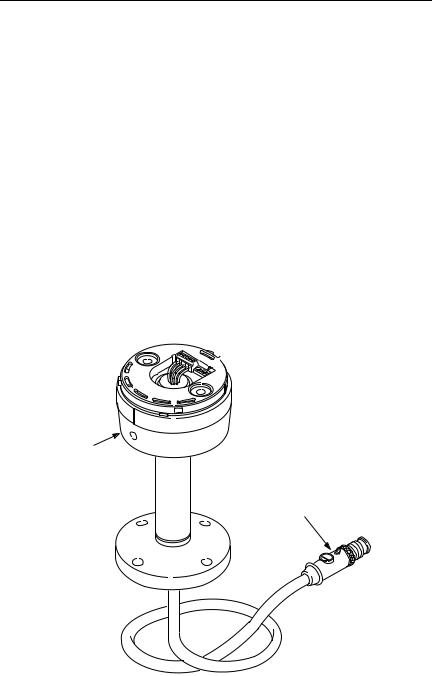
Base Features
Figure 1.1
Rotary
Switches
855T Base
DeviceNet™
Connector
Publication 855T-UM001C-EN-P May 2005
Overview of DeviceNet Stack Light |
1-3 |
Module Positions
Figure 1.2
5
4
3
2
1
Rotary Switches
The DeviceNet Stack Light has three 10-position rotary switches for setting:
•DeviceNet Data Rate
•DeviceNet Node Address
The rotary switches are located on the circuit board on the top of the base. The switch settings and functions are shown below.
Figure 1.3
Data Rate |
Node Address |
MSB LSB
DeviceNet Connection
The DeviceNet Stack Light receives all power and communications through the DeviceNet Cable. A separate power supply is not required. This is the only external connection to the DeviceNet Stack Light.
Publication 855T-UM001C-EN-P May 2005
1-4 Overview of DeviceNet Stack Light
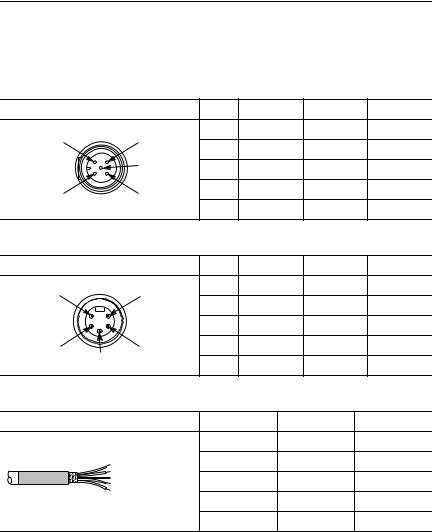
The DeviceNet Stack Light connects to the DeviceNet Network using a cable with a micro connector, a mini connector, or an open-style connector.
Table 1.B DeviceNet Micro Connector
Micro Connector |
|
Pin # |
Signal |
Function |
|
Color |
1 DRAIN |
|
1 |
SHIELD |
SHIELD |
|
Uninsulated |
4 WHITE |
2 |
VDC+ |
Power Supply |
Red |
||
|
|
|||||
|
5 BLUE |
3 |
COM |
Common |
|
Black |
2 RED |
3 BLACK |
4 |
CAN_H |
Signal High |
|
White |
5 |
CAN_L |
Signal Low |
|
Blue |
||
|
|
|
||||
Table 1.C DeviceNet Mini Connector |
|
|
|
|
|
|
Mini Connector |
|
Pin # |
Signal |
Function |
|
Color |
1 |
5 |
1 |
SHIELD |
SHIELD |
|
Uninsulated |
|
|
|
|
|
||
|
2 |
VDC+ |
Power Supply |
Red |
||
|
|
|||||
|
|
3 |
COM |
Common |
|
Black |
2 |
4 |
4 |
CAN_H |
Signal High |
|
White |
|
|
|
|
|
||
3 |
|
5 |
CAN_L |
Signal Low |
|
Blue |
|
|
|
||||
Table 1.D DeviceNet Open-Style Connector |
|
|
|
|
|
|
Open-Style Connector |
|
Signal |
|
Function |
Color |
|
|
|
COM |
|
Common |
Black |
|
|
V-(black) |
CAN_L |
|
Signal Low |
Blue |
|
|
V+(red) |
SHIELD |
|
Shield |
Uninsulated |
|
|
Drain Wire (bare) |
|
||||
|
CAN_H (white) |
CAN_H |
|
Signal High |
White |
|
|
CAN_L (blue) |
|
||||
|
|
VDC+ |
|
Power Supply |
Red |
|
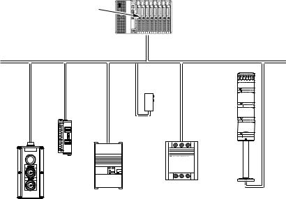
Typical DeviceNet Configuration
A DeviceNet Network supports multiple Stack Light devices and allows them to communicate with other network devices (up to 64).
The DeviceNet Stack Light operates on the network as a slave device. It does not initiate communications except for a duplicate node address check on power-up. The master writes data to, and receives data back from, the DeviceNet Stack Light.
The following DeviceNet configuration shows a variety of products operating as slaves to a PLC-5 controller with a 1771-SDN DeviceNet Scanner Module.
Publication 855T-UM001C-EN-P May 2005
Overview of DeviceNet Stack Light |
1-5 |
Figure 1.4
PLC-5 Controller
DeviceNet™ Scanner Module
DeviceNet™ Network
Sensor
Block I/O
SMC
|
Smart Motor Controller |
Drive |
Stack Light |
|
RediSTATION
DeviceNet Components
DeviceNet Cables and components are available from Allen-Bradley as separate cat. nos.
It is your responsibility to install and implement the DeviceNet Network and supported devices according to the DeviceNet guidelines.
Replacement Parts
The DeviceNet Stack Light Bases and pre-assembled stacks come with all the parts required to install and use the product. The installer needs only to supply the mounting hardware.
Replacement parts for 855T components (modules, replacement gaskets, and replacement lamps) are available as separate cat. nos. Refer to the Signal Solutions Selection Guide (Publication 855-SG001*-EN-P) or the Industrial Controls Catalog.
Publication 855T-UM001C-EN-P May 2005

Chapter 2
Quick Start
Chapter Objectives
This chapter provides the necessary steps to get the DeviceNet Stack Light operating on the network. It contains the following sections:
Table 2.A
Section |
Page |
Section |
Page |
|
|
|
|
Data Rate Configuration |
2-1 |
Connection to the Network |
2-2 |
|
|
|
|
Node Address Configuration |
2-2 |
Stack Light Parameter Configuration |
2-3 |
|
|
|
|
Installing the Modules |
2-2 |
— |
— |
|
|
|
|
Data Rate Configuration
Rotary switch 3 (S3) sets the data rate at which the DeviceNet Stack Light communicates on the DeviceNet Network. The factory default setting is 125 KB.
Figure 2.1
DATA PGM |
4 |
6 NODE ADDRESS 4 |
6 |
RATE 500K |
NOT |
(00 – 63, PGM) |
8 |
USED 2 |
2 |
||
250K125K |
MSD 0 |
PGM |
0 |
LSD |
For more information on data rate configuration, refer to Chapter 3 — Installation and Mounting (Setting the Data Rate).
Publication 855T-UM001C-EN-P May 2005
Quick Start |
2-2 |
Node Address Configuration
Rotary switches 1 (S1) and 2 (S2) set the node address (0…63) of the stack light on the DeviceNet Network. The factory default is 63.
Figure 2.2
DATA PGM |
4 |
6 NODE ADDRESS 4 |
6 |
RATE 500K |
NOT |
(00 – 63, PGM) |
8 |
USED 2 |
2 |
||
250K125K |
MSD 0 |
PGM |
0 |
LSD |
For more information on node address configuration, refer to Chapter 3 — Installation and Mounting (Setting the DeviceNet Node Address).
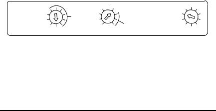
Installing the Modules
The stack light modules are installed to the base by placing a sealing o-ring between the base and the module, lining up the arrow on the bottom of the module with the line on the top of the prior module or base, and twisting the top module clockwise to lock them into place.
|
|
The DeviceNet Base is compatible with all 24V DC 855T modules. |
|
IMPORTANT |
|
|
|
|
|
|
|
|
|
|
For more information on different modules, refer to the Signal Solutions Selection Guide (Publication 855-SG001*-EN-P) or the Industrial Controls Catalog.
Connection to the Network
Wire the DeviceNet Stack Light to an operating network. If the device is an 855T-DSxxxx, the wires should be connected to a terminal block. If the device is an 855T-DMxxxx or 855T-DLxxxx, it will be connected with the quick disconnect connector. The device is fully powered by the network, therefore it is important that the device is located near a power supply.
For more information on system installation, refer to the DeviceNet Media Design Installation Guide (Publication DNET-UM072*-EN-P).
Publication 855T-UM001C-EN-P May 2005
2-3 Quick Start
Stack Light Parameter Configuration
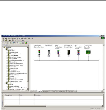
For proper operation, the parameters of the stack light must be configured. There are several different parameters that can be configured, but the critical parameters are Module Type and Module Mode. The parameters can be configured using RSNetWorx for DeviceNet.
Figure 2.3
To access the parameter configuration screen from the on-line view, double-click the stack light icon.
Publication 855T-UM001C-EN-P May 2005
Quick Start |
2-4 |
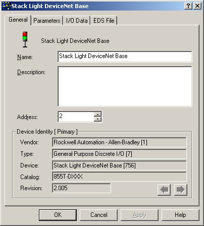
Figure 2.4
Select the Device Parameters tab.
Publication 855T-UM001C-EN-P May 2005
2-5 Quick Start
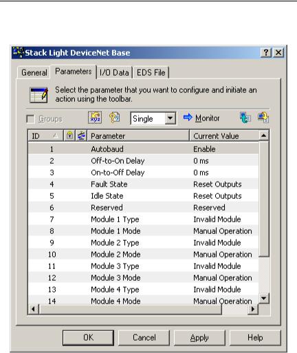
Figure 2.5
The stack light will work without any parameter changes, but for flashing patterns and bulb burnout detection, parameters must be changed. For more information on device configuration, refer to Chapter 4 — Operations (Parameter Configuration) and RSNetWorx for DeviceNet documentation.
Publication 855T-UM001C-EN-P May 2005
Quick Start |
2-6 |
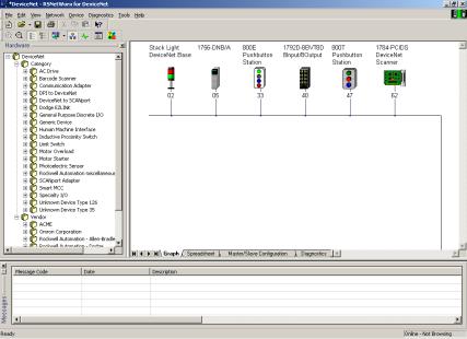
Scanner Configuration
For proper operation, the scanner must be configured. The following graphics show the configuration of a 1756-DNB from the RSNetWorx for DeviceNet software.
Figure 2.6
To access the Scanner Module Configuration screen from an on-line view, double-click the 1756-DNB scanner icon.
Publication 855T-UM001C-EN-P May 2005

2-7 Quick Start
Figure 2.7
To access the Scanlist Editor, select the Scanlist tab.
Publication 855T-UM001C-EN-P May 2005
Quick Start |
2-8 |
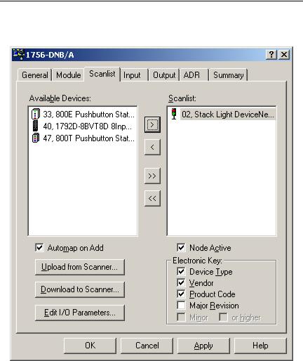
Figure 2.8
Add Stack Light DeviceNet Base to the Scanlist. Select the device in the Available Devices list. To have the software automatically assign I/O addresses, select the Automap on Add selection box. Click the > button.
Publication 855T-UM001C-EN-P May 2005
2-9 Quick Start
Figure 2.9
To view/edit I/O parameters, click Edit I/O Parameters.
Publication 855T-UM001C-EN-P May 2005
 Loading...