


Multifunction Digital Timer
700-HX
User Manual

Important User Information Because of the variety of uses for the products described in this publication, those responsible for the application and use of this control equipment must
satisfy themselves that all necessary steps have been taken to assure that each application and use meets all performance and safety requirements, including any applicable laws, regulations, codes and standards.
The illustrations, charts, sample programs and layout examples shown in this guide are intended solely for purposes of example. Since there are many variables and requirements associated with any particular installation, Allen-Bradley does not assume responsibility or liability (to include intellectual property liability) for actual use based upon the examples shown in this publication.
Rockwell Automation publication SGI-1.1, Safety Guidelines for the Application, Installation and Maintenance of Solid-State Control (available from your local Rockwell Automation sales office or Allen-Bradley distributor), describes some important differences between solid-state equipment and electromechanical devices that should be taken into consideration when applying products such as those described in this publication.
Reproduction of the contents of this copyrighted publication, in whole or part, without written permission of Rockwell Automation, is prohibited.
Throughout this manual we use notes to make you aware of safety considerations:
ATTENTION |
Identifies information about practices or circumstances |
|
that can lead to personal injury or death, property damage |
||
|
||
|
or economic loss |
!
Attention statements help you to:
•identify a hazard
•avoid a hazard
•recognize the consequences
IMPORTANT |
Identifies information that is critical for successful |
|
application and understanding of the product. |
||
|
||
|
||
|
|
European Communities (EC)
Directive Compliance
If this product has the CE mark it is approved for installation within the European Union and EEA regions. It has been designed and tested to meet the following directives.
EMC Directive
This product is tested to meet the Council Directive 89/336/EC Electromagnetic Compatibility (EMC) by applying the following standards, in whole or in part, documented in a technical construction file:
•EN 50081-2 EMC — Generic Emission Standard, Part 2 — Industrial Environment
•EN 50082-2 EMC — Generic Immunity Standard, Part 2 — Industrial Environment
This product is intended for use in an industrial environment.
Low Voltage Directive
This product is tested to meet Council Directive 73/23/EEC Low Voltage, by applying the safety requirements of EN 61010-1 safety requirements for electrical equipment for measurement, control and laboratory use--Part 1 General Safety Requirements.
This equipment is classified as open equipment and must be mounted as instructed in an enclosure during operation to provide safety protection.

Preface
Manual Objectives
Who Should Use This
Manual
Counter/Timer Mode
Explanation
The purpose of this manual is to provide you with the additional information necessary to apply the 700-HX Multifunction Digital Timer. Described in this manual are methods for applying and troubleshooting this product.
This manual is intended for qualified personnel responsible for setting up and servicing these devices. You must have previous experience with and a basic understanding of wiring diagrams, configuration procedures, related equipment, and safety precautions.
In this manual we refer to the Timer Output Modes with the following designations:
A: Signal ON delay 1
A-1: Signal ON delay 2
A-2: Power ON delay 1
A-3: Power ON delay 2
B: Repeat Cycle 1
B-1: Repeat Cycle 2
D:Signal OFF delay
E:One Shot
F:Cumulative
Z: ON/OFF-duty adjustable repeat cycle
S: Stop Watch
toff: Flicker OFF start 1(Timer resets when power comes on)
ton: Flicker ON start 1 (Timer resets when power comes on)
toff-1: Flicker OFF start 2(Timer does not reset when power comes on)
ton-1: Flicker ON start 2 (Timer does not reset when power comes on)
Note: In this manual the 700-HX Multifunction Digital Timer will be referred to as “700-HX.” For further information, please refer to the Industrial Controls Catalog or www.ab.com/catalogs.
Publication 700-UM002B-EN-D June 2010

Preface 2
Publication 700-UM002B-EN-D - June 2010

Chapter 1
Product Overview
Bill of Material
Your 700-HX Multifunction Digital Timer product package includes the following items:
Item No. |
Description |
Quantity |
|
|
|
700-HX |
Digital Timing Relay |
1 |
|
|
|
— |
6-Language Instruction Sheet |
1 |
|
|
|
— |
Rubber Gasket |
1 |
|
|
|
Basic Product Information
Cat. No. |
Input |
Output Modes |
Timing Ranges |
Sockets |
Output |
Pins |
|
Voltage |
|
|
|
|
|
700-HX86SA17 |
100…240 |
A mode: Signal ON-Delay 1 |
|
|
|
|
|
V AC |
A-1 mode: Signal ON-Delay 2 |
|
|
|
|
|
|
A-2 mode: Power ON-Delay 1 |
0.000…9.999 s |
|
|
|
|
|
A-3 mode: Power On-Delay 2 |
|
|
|
|
|
|
0.000…99.99 s |
|
|
|
|
|
|
B mode: Repeat Cycle 1 |
|
|
|
|
|
|
0.000…999.9 s |
|
|
|
|
|
|
B-1 mode: Repeat Cycle 2 |
|
|
|
|
|
|
0.000…9999 s |
|
|
|
|
|
|
D mode: Signal OFF-delay |
700-HN100 |
|
|
|
|
|
0.000…99 min. 59 s |
SPDT |
8 |
||
|
12…24V |
E mode: One Shot |
||||
|
0.000…999.9 min. |
700-HN125 |
||||
700-HX86SU24 |
DC |
F mode: Cumulative |
|
|
||
0.000…9999 min. |
|
|
|
|||
|
24V AC |
Z mode: On/Off duty adjustable repeat cycle |
|
|
|
|
|
0.000…99 h 59 min. |
|
|
|
||
|
|
S mode:stop watch |
|
|
|
|
|
|
0.000…999.9 h |
|
|
|
|
|
|
toff: Flicker OFF start 1 |
|
|
|
|
|
|
0.000…9999 h |
|
|
|
|
|
|
ton: Flicker ON start 1 |
|
|
|
|
|
|
|
|
|
|
|
|
|
toff-1: Flicker OFF start 2 |
|
|
|
|
|
|
ton-1: Flicker ON start 2 |
|
|
|
|
|
|
|
|
|
|
|
Publication 700-UM002B-EN-D - June 2010

1-2 Product Overview
Accessories
(Order Separately)
Cat. No. |
Description |
Pkg. Qty. |
700-HN100 |
Screw Terminal Tube Base Sockets — Panel or DIN Rail |
10 |
|
Mounting Guarded Terminal Construction |
|
|
8-pin for use with Bulletin 700-HX timing relays. Order |
|
|
must be for 10 sockets or multiples of 10. |
|
700-HN125 |
Screw Terminal Tube Base Sockets — Panel or DIN Rail |
10 |
|
Mounting |
|
|
Open Style Construction |
|
|
8-pin for use with Bulletin 700-HX timing relays. Order must |
|
|
be for 10 sockets or multiples of 10. No retainer clip |
|
|
required. |
|
199-DR1 |
DIN Rail Mounting Pack |
10 |
|
Standard 35 x 7.5 mm DIN Rail, 1 meter long, 10 rails per |
|
|
package. Order must be for 10 rails or multiples of 10. |
|
700-HN108 |
Specialty Socket |
10 |
|
8-pin backwired socket with solder terminals for use with |
|
|
Bulletin 700-HX timing relays. Order must be for 10 sockets |
|
|
or multiples of 10. |
|
700-HN130 |
Frame Adapter |
1 |
|
For flush or door mounting of all Bulletin 700-HR and -HX |
|
|
timers. |
|
700-HN132 |
Protective Cover |
1 |
|
Helps prevent tampering of timing and mode settings. |
|
|
Provides a degree of protection against water and dirt from |
|
|
entering the front of the relay. For use with all Bulletin |
|
|
700-HRs and -HX timing relays. |
|
700-N40 |
Pre-printed identification tags— contains 10 sheets of |
10 |
|
pre-printed and blank tags. Each sheet contains 13 sets of |
|
|
the markings CR…9CR, TR…9TR, M…9M, F, R, 1S, and |
|
|
117 blank tags. Tags are peel-off with sticky backing for |
|
|
easy placement on relays. |
|
|
|
|
700-N41 |
Blank identification tags— contains 10 sheets of blank |
10 |
|
identification tags for customer specialized printing. Each |
|
|
sheet contains 546 blank tags. Tags are peel-off with sticky |
|
|
backing for easy placement on relays. |
|
|
|
|
Publication 700-UM002B-EN-D - June 2010
Chapter 2
Product Features
Block diagram
|
|
|
|
|
|
|
|
|
|
|
|
|
|
|
|
|
|
|
|
|
|
|
|
|
|
|
|
|
|
|
|
|
|
|
|
|
|
|
|
|
|
|
|
|
|
|
Output circuit |
|
|
|
|
|
|
|
(Basic |
|
|||||||||||
|
|
|
|
|
|
|
|
|
|
|
|
|
|
|
|
|
|
|
|
|
|||||||||||||
|
|
|
|
|
|
|
|
|
|
|
|
|
|
|
|
|
|
|
|
|
|
|
|
|
|
||||||||
|
|
|
|
|
|
|
|
|
|
|
|
|
|
|
|
|
|
|
|
|
|
|
|
|
|
||||||||
|
|
|
|
|
|
|
|
|
|
|
|
|
|
|
|
|
|
|
|
|
|
|
|
|
|
||||||||
|
|
|
|
|
|
|
|
|
|
|
|
|
|
|
|
|
|
|
|
|
|
|
|
|
insulation) |
|
|||||||
|
|
|
|
|
|
|
|
|
|
|
|
|
|
|
|
|
|
|
|
|
|
|
|
|
|
|
|
|
|
|
|
|
|
|
|
|
|
|
|
|
|
|
|
|
|
|
|
|
|
|
|
|
|
|
|
|
|
|
Display circuit |
|
|||||||
|
|
|
|
|
|
|
|
|
|
|
|
|
|
|
|
|
|
|
|
|
|
|
|
|
|
|
|
|
|
|
|
|
|
|
Input circuit |
|
|
|
|
|
|
Internal control |
|
|
|
|
|
|
|
|
|
|
|
|
|
|
|
|
|||||||||
|
|
|
|
|
|
|
|
|
|
|
|
|
|
circuit |
|
|
|
|
|
|
|
|
|
|
|
|
|
|
|
|
|||
|
|
|
|
|
|
|
|
|
|
|
|
|
|
|
|
|
|
|
|
|
|
|
|
|
Key switch |
|
|||||||
|
|
|
|
|
|
|
|
|
|
|
|
|
|
|
|
|
|
|
|
|
|
|
|
|
circuit |
|
|||||||
|
|
|
|
|
|
|
|
|
|
|
|
|
|
|
|
|
|
|
|
|
|
|
|
|
|
|
|
|
|
|
|
|
|
|
|
|
|
|
|
|
|
|
|
|
|
|
|
|
|
|
|
|
|
|
|
|
|
|
|
|
|
||||||
|
|
|
|
|
|
|
|
|
|
|
|
|
|
|
|
|
|
|
|
|
|
|
|
|
(See note.) |
|
|||||||
|
|
|
|
|
|
|
|
|
|
|
|
|
|
|
|
|
|
|
|
|
|
|
|
|
|
|
|
|
|
|
|
|
|
|
|
|
|
|
|
|
|
|
|
|
|
|
|
Power supply |
|
|
|
|
|
|
|
|
|
|
|
|
|
|
|
|
|||
|
|
|
|
|
|
|
|
|
|
|
|
|
|
circuit |
|
|
|
|
|
|
|
|
|
|
|
|
|
|
|
|
|||
|
|
|
|
|
|
|
|
|
|
|
|
|
|
|
|
|
|
|
|
|
|
|
|
|
|
|
|
|
|
||||
|
|
|
|
|
|
|
|
|
|
|
|
|
|
|
|
|
|
|
|
|
|
|
|
|
|
|
|
|
|
||||
|
|
|
|
|
|
|
|
|
|
|
|
|
|
|
|
|
|
|
|
|
|
|
|
|
|
|
|
|
|
|
|
|
|
|
|
|
|
|
|
|
|
|
|
|
|
|
|
|
|
|
|
|
|
|
|
|
|
|
|
|
|
|
|
|
|
|
|
Note: 700-HX86SA17: Basic insulation is provided 700-HX86SU24: Basic insulation is not provided
Inputs |
Start signal |
Stops timing in A-2 and A-3 (power ON delay) |
|
|
modes. |
|
|
Starts and stops timing in S mode. |
|
|
Start timing in other modes. |
|
Reset |
Resets present value. (In elapsed time mode, the |
|
|
present value returns to 0; in remaining time |
|
|
mode, the present value returns to the set value.) |
|
|
Count inputs are not accepted and control output |
|
|
turns OFF while reset input is ON. |
|
|
Reset indicator is lit while reset input is ON. |
|
Gate |
Inhibits timer operation. |
Outputs |
Control output (OUT) |
Outputs take place according to designated |
|
|
operating mode when timer reaches |
|
|
corresponding set value. |
Gate capability not available. |
|
|
Publication 700-UM002B-EN-D - June 2010
2-2 Product Features
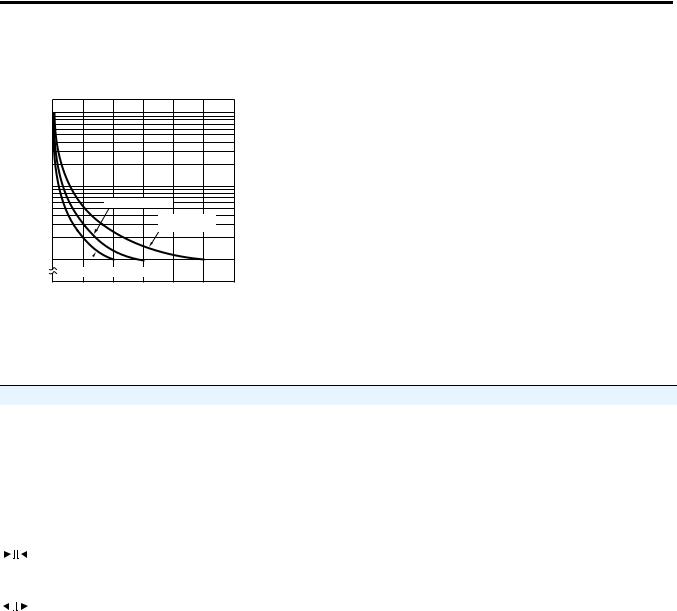
Engineering Data
(Reference Values)
) |
|
|
|
|
|
|
4 |
1,000 |
|
|
|
|
|
10 |
|
|
|
|
|
|
|
|
|
|
|
|
|
( |
500 |
|
|
|
|
|
operations |
|
|
|
|
|
|
100 |
|
|
|
|
|
|
Switching |
|
|
|
|
|
|
50 |
|
30V DC L/R=7 ms |
|
|||
|
|
|
|
|
||
|
|
|
|
250V DC/30V |
||
|
|
|
|
cos =1 |
|
|
|
10 |
|
|
|
|
|
|
|
250V AC cos =0.4 |
|
|
|
|
|
0 |
1 |
2 |
3 |
4 |
5 |
Load current (A)
Reference:A maximum current of 0.15 A can be switched at 125V DC (cosφ=1) and a maximum current of 0.1 A can be switched if L/R is 7 ms. In both cases, a life of 100,000 operations can be expected. The minimum applicable load is 10 mA at 5V DC (failure level: P).
Specifications
Electrical Ratings
Pilot Duty Rating |
|
NEMA B300 |
|
Rated supply voltage |
|
100 to 240V AC, 24V AC/12 to 24V DC (50/60Hz) (permissible |
|
|
|
|
ripple: 20%(p-p) max.) |
|
|
|
|
Operating voltage range |
|
85%…110% of rated supply voltage |
|
|
|
|
|
Power consumption |
100…240V AC |
4.3 VA |
|
|
|
24V AC/12…24V DC |
|
|
|
3.4 VA/1.7 W |
|
|
|
|
|
|
|
|
|
Inrush Current |
100…240V AC |
3 A |
|
|
|
24V AC/12…24V DC |
5 A |
|
|
|
|
|
120V AC |
|
30 A |
|
|
|
|
Make |
240V AC |
|
15 A |
|
|
||
|
|
|
|
|
120V AC |
|
3 A |
|
|
|
|
Break |
240V AC |
|
1.5 A |
|
|
||
|
|
|
|
Hp at 120V AC |
|
1/4 Hp |
|
|
|
|
|
Hp at 240V AC |
|
1/3 Hp |
|
|
|
|
|
Mechanical |
|
|
|
Mounting method |
|
Flush mounting, surface mounting, DIN mounting |
|
|
|
|
|
Display |
|
|
7-segment, negative transmissive LCD; |
|
|
|
Present value (red, 12 mm high characters); Set value (green, |
|
|
|
6 mm high characters) |
|
|
|
|
Digits |
|
|
4 digits |
|
|
|
|
Timer |
|
Time ranges |
0.000…9.999 s, 0.00…99.99 s, 0.0…999.9 s, 0…9999 s, |
|
|
|
0 min. 0 s…99 min. 59 s, 0.0…999.9 min., 0 h 00 min.…99 h |
|
|
|
59 min., 0.0 h…999.9 h, 0 h…9999 h |
|
|
|
|
|
|
Timer modes |
Elapsed time (Up), remaining time (Down), selectable |
|
|
|
|
|
|
Output modes |
A, A-1, A-2, A-3, B, B-1, D, E, F, Z, S, toff, ton, toff-1, or ton-1 |
|
|
|
|
Publication 700-UM002B-EN-D - June 2010

Product Features |
2-3 |
Electrical Ratings
Inputs |
Input signals |
Start, reset |
|
Input method |
No-voltage input via:NPN transistor or switching of contact |
|
|
|
|
Start, reset |
Minimum input signal width: 1 or 20 ms (selectable) |
|
|
|
|
Power reset |
Minimum power-opening time: 0.5 s (Except for A-3, B-1, and |
|
|
F mode) |
|
|
|
Control output |
|
SPDT contact output: 5 A at 250V AC, resistive load |
|
|
(cosine=1) |
|
|
Minimum applied load: 10 mA at 5V DC (failure level: P, |
|
|
reference value) |
|
|
|
External Power Supply |
|
No |
|
|
|
Key Protect |
|
Yes |
|
|
|
Memory backup |
|
EEP-ROM (overwritten 100,000 times min.), which can store |
|
|
data for 10 years min. |
Accuracy of Operating Time and Setting Error |
Power-ON start: +-0.01% +-50 ms max.* |
|
|
|
* to be rated against set value |
|
|
Signal start: +- 0.005 +-30 ms max. * |
|
|
* to be rated against set value |
|
|
Signal start at transistor output model: +- 0.005% +-3 ms |
|
|
max. |
|
|
If the set value is within the sensor waiting time |
|
|
(250 ms max.) |
|
|
|
|
The values are based on the set value. |
|
|
The value is applied for a minimum pulse width of 1 ms. |
|
Characteristics
Insulation resistance |
|
100 MΩ min. (at 500V DC) |
|
|
|
|
|
Dielectric strength |
|
2000V AC, 50/60Hz for 1 min. between current-carrying terminals and |
|
|
|
non-current-carrying metal parts |
|
|
|
(1000V AC for 24V AC/12 to 24V DC type), |
|
|
|
1000V AC, 50/60 Hz for 1 min. between non-continuous contacts |
|
Noise immunity |
|
'+-1.5 kV (between power terminals) for 100 to 240V AC, +-480V for 24V AC/12 |
|
|
|
to 24VDC, and +-600V (between input terminals), square-wave noise by noise |
|
|
|
simulator (pulse width: 100 ns/1 μs, 1-ns rise) |
|
Static immunity |
|
±8 kV (malfunction), ±15 kV (destruction) |
|
|
|
|
|
Vibration resistance |
Malfunction |
10…55 Hz with 0.35 mm single amplitude each in three directions for 10 min. |
|
|
|
|
|
Shock resistance |
Malfunction |
98 m/s2 (approx. 10 G) each in three directions |
|
Life expectancy |
Mechanical |
10 million operations min. |
|
|
|
|
|
|
Electrical |
100,000 operations min. (5 A at 250V AC, resistive load) |
|
|
|
|
|
EMC |
|
(EMI) |
EN61812-1 |
|
|
Emission Enclosure: |
EN55011 Group1 class A |
|
|
Emission AC mains: |
EN55011 Group1 class A |
|
|
(EMS) |
EN61812-1 |
|
|
Immunity ESD: |
EN61000-4-2: 4 kV contact discharge (level2) |
|
|
|
8 kV air discharge (level3) |
|
|
Immunity RF-interference: EN61000-4-3: 10 V/m |
|
|
|
|
|
Publication 700-UM002B-EN-D - June 2010
2-4 Product Features
Approved standards |
|
UL508, CSA C22.2 No.14 |
|
|
Conforms to EN 61812-1 |
|
|
(Pollution degree 2/overvoltage category III) |
|
|
Conforms to VDE0106/P 100 (Finger Protection), conforms to NEMA output |
|
|
rating (N/F) |
Enclosure ratings |
|
Panel surface:IP66 and NEMA Type 4X (indoors) |
|
|
|
Weight |
|
Approx. 100 g |
|
|
|
|
An attached waterproof packing is necessary to ensure IP66 waterproofing between the |
|
|
700-HX and installation pan. |
|
Nomenclature
Display Section
1.Key Protect Indicator (orange)
2.Control Output Indicator (orange)
3.Reset Indicator (orange)
4.Present Value Display (Main display)
(Character height: 12 mm, red *)
* Characters on models with screw terminals can be switched between red, green, and orange.
5. Time Unit Indicators
(Color is same as present value display.) (If the time range is 0 min, 0 h, 0.0 h, or 0 h 0 min, these indicators flash to indicate timing operation.)
6. Set Value Display (Sub-display)
(Character height: 6 mm, green)
7. Set Value 1, 2 Indicator (green)
Character Size |
Character Size |
||
for Present |
for Set Value |
||
Value Display |
Display |
||
|
|
|
|
1
2
3
8
9
12
4 |
5 |
6 |
7 |
10
11
Operation Key
8. Mode Key
(Changes modes and setting items)
9. Reset Key
(Resets present value and output)
10.Up Keys 1 to 4
11.Down Keys 1 to 4
Switches
Front View
12. Key-protect Switch
(Default setting) |
OFF |
|
|
|
ON |
|||||||||||||||||||
(Disabled) |
|
|
|
(Enabled) |
||||||||||||||||||||
|
|
|
|
|
|
|
|
|
|
|
|
|
|
|
|
|
|
|
|
|
|
|
|
|
|
|
|
|
|
|
|
|
|
|
|
|
|
|
|
|
|
|
|
|
|
|
|
|
|
|
|
|
|
|
|
|
|
|
|
|
|
|
|
|
|
|
|
|
|
|
|
|
|
|
|
|
|
|
|
|
|
|
|
|
|
|
|
|
|
|
|
|
|
|
|
|
|
|
|
|
|
|
|
|
|
|
|
|
|
|
|
|
|
|
|
|
|
|
|
|
|
|
|
|
12mm |
6mm |
||||
|
|
|
|
|
|
|
|
|
|
|
|
|
|
|
|
|
|
|
|
|
|
|
|
Publication 700-UM002B-EN-D - June 2010
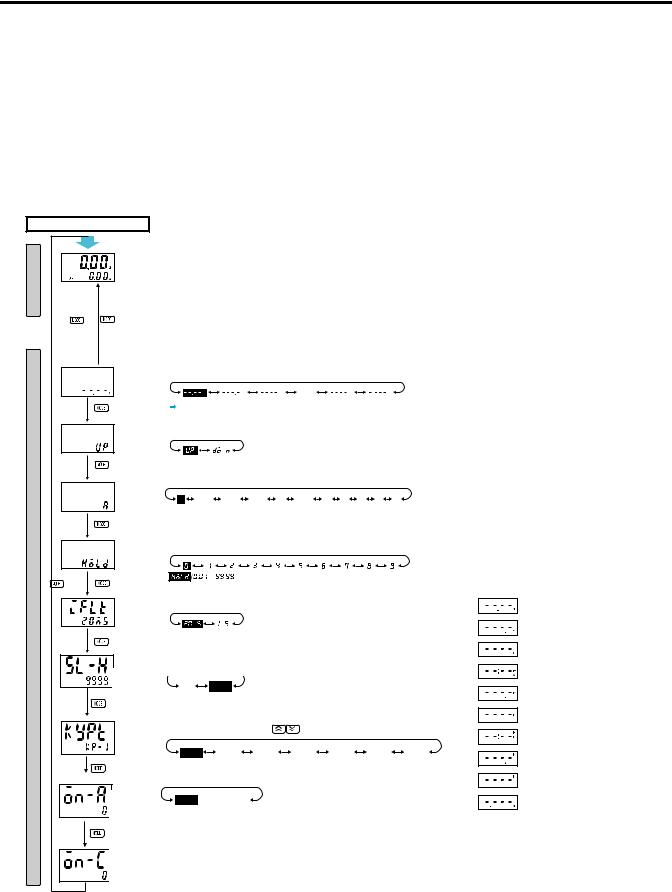
Chapter 3
Functions
|
|
|
|
|
|
|
Settings For Advanced Functions |
||||||||
|
Power ON |
|
|
|
|
|
|
|
|
|
|
|
|
|
|
mode |
|
For details on operations in run mode, refer to 3-10. |
|
|
|
|
|||||||||
|
Note: |
1. |
If the mode is switched to the function setting mode during operation, |
||||||||||||
|
|
|
|
|
operation will continue. |
|
|
|
|
|
|
||||
Run |
|
|
|
2. |
Changes made to settings in function setting mode are enabled for the |
||||||||||
|
|
|
|
first time when the mode is changed to run mode. Also, when settings |
|||||||||||
|
See note 1. |
See note 2. |
|
|
are changed, the timer is reset (time initialized and output turned OFF). |
||||||||||
|
|
|
|
|
|
|
|
|
|
|
|
|
|
||
|
3 s min. |
3 s min. |
Press the mode button for several seconds to display the Time Range setting |
||||||||||||
|
screen. |
|
|
|
|
|
|
|
|
|
|
|
|||
|
|
|
|
|
|
|
|
|
|
|
|
|
|
||
|
|
|
|
Set the time range |
using the |
|
|
keys. |
|
|
|
||||
|
timr Time range |
|
|
|
|
|
|
|
|
|
|
|
|
|
|
|
|
|
|
|
s |
|
s |
|
s |
…… |
|
h |
|
s |
|
|
|
|
|
Set the timer mode |
using the |
|
|
keys. |
|
|
|
||||
|
timm Timer mode |
|
|
|
|
|
|
|
|
|
|
|
|
|
|
|
|
|
|
|
|
|
w |
|
|
|
|
|
|
|
|
|
|
|
Set the output mode using the |
|
|
keys. |
|
|
|
||||||
|
outm |
Output mode |
a a-1 a-2 a-3 b b-1 d e f z s |
||||||||||||
|
|
|
|
||||||||||||
mode |
|
|
|
(A) |
(A-1) |
(A-2) |
(A-3) |
(b) |
(b-1) |
(d) |
(E) |
(F) |
(Z) |
(S) |
|
|
|
|
|
|
|
|
|
|
|
|
|
|
|
|
|
setting |
otim |
|
|
Set each digit for the output time using the corresponding |
|
keys. |
|||||||||
|
|
|
|
||||||||||||
Function |
Output time |
|
|
|
|
|
|
|
|
|
|
|
|
|
|
|
|
|
|
|
|
|
|
|
|
|
|
|
|
||
|
|
|
|
(If the output time is set to 0.00,hold is displayed.) |
|
|
|
||||||||
|
|
Input signal |
|
Displayed for modes A, A-1, A-2, A-3, B, and B-1 only. |
|
|
|
||||||||
|
|
|
|
|
|
|
|
|
|
|
|
|
|
|
|
|
|
width |
|
|
m |
|
m |
|
|
|
|
|
|
|
|
|
|
|
|
|
|
|
|
|
|
|
|
|
|
||
|
|
|
|
20 ms 1 ms |
|
|
|
|
|
|
|
|
|||
|
|
Set value |
|
Set the key protect level using the |
|
|
keys. |
|
|
|
|||||
|
|
|
|
|
|
|
|
|
|
|
|
|
|
|
|
|
|
upper limit |
|
|
|
|
|
|
|
|
|
|
|
|
|
|
|
|
|
1 |
|
|
9999 |
|
|
|
|
|
|
|
|
|
|
|
|
(1) |
|
(9999) |
|
|
|
|
|
|
|
|
|
|
|
Key protect |
|
Set the key protect level using the |
|
keys. |
|
|
|
|
|
||||
|
|
|
|
|
|
|
|
|
|
|
|
|
|
|
|
|
|
level |
|
|
|
|
|
|
|
|
|
|
|
|
|
|
|
|
|
kp-1 |
|
kp-2 |
kp-3 |
|
kp-4 |
|
kp-5 |
|
kp-6 |
kp-7 |
|
|
|
|
|
(KP-1) |
|
(KP-2) |
(KP-3) |
|
(KP-4) |
|
(KP-5) |
|
(KP-6) |
(KP-7) |
|
|
|
Output on |
|
|
|
|
|
|
|
|
|
|
|
|
|
|
|
countOutput ONalarm |
|
|
0 |
~ 9999 |
|
|
|
|
|
|
|
|
|
|
|
setcountvaluealarm |
|
|
|
|
|
|
|
|
|
|
|||
|
|
set value |
|
(0 x 1000 times) |
|
(9999 x 1000 times) |
|
|
|
|
|
|
|
||
|
|
Output on |
|
|
|
|
|
|
|
|
|
|
|
|
|
|
|
countO tput ON |
Note: The monitor value is only displayed. |
|
|
|
|
|
|
||||||
|
|
c unt monitor |
|
|
|
|
|
|
|||||||
|
|
monitor set |
|
It cannot be set. |
|
|
|
|
|
|
|
|
|||
|
|
value |
|
|
|
|
|
|
|
|
|
||||
|
|
value |
|
|
|
|
|
|
|
|
|
|
|
|
|
Time Range List
Display |
Set Value |
0.01 s to 99.99 s (default setting)
0.1 s to 999.9 s
1 s to 9,999 s
0 min 01 s to 99 min 59 s
0.1 min to 999.9 min
1 min to 9,999 min
0 h 01 min to 99 h 59 min
0.1 h to 999.9 h
1 h to 9,999 h
0.001s to 9.999 s
Publication 700-UM002B-EN-D - June 2010

3-2 Functions
Explanations of Functions Time Range (timr)
Set the range to be timed in the range 0.000 s… 9,999 h. Use the operation keys if these settings are required.
Timer Mode (timm )
Set either the elapsed time (UP) or remaining time (DOWN) mode.
Output Mode (outm)
Set the output mode. The possible settings are A, A-1, A-2, A-3, B, B-1, D, E, F, Z and S. (For details on output mode operation, refer to “Timing Charts” on page 3-11.)
Output Time (otim )
When using one-shot output, set the output time for one-shot output (0.01… 99.99 s). One-shot output can be used only if the selected output mode is A, A-1, A-2, B, or B-1. If the output time is set to 0.00, hold is displayed, and the output is held.
Input Signal Width (iflt)
Set the minimum signal input width (20 ms or 1 ms) for signal and reset inputs. The same setting is used for all external inputs (signal and reset). If contacts are used for the input signal, set the input signal width to 20 ms. Processing to eliminate chattering is performed for this setting.Set the key protect level.
Set Value Upper Limit (sl-h)
Set the upper limit for the set value when it is set in Run Mode. The limit can be set to between 1 and 9999. This setting does not apply to the ON duty in Z mode.
Output ON Count Alarm Set Value (on-a)
Set the alarm value for the output ON count.The limit can be set to between 0 x 1000 times and 9999 x 1000 times. (The rightmost three digits will not be displayed.) If the total ON count of the output exceeds the alarm set value, e3 will be displayed on the Timer to indicate that the output ON count alarm value was exceeded.
Output ON Count Monitor Value (on-c)
The monitor value is only displayed. It cannot be set. The value will be between 0 x 1000 times and 9999 x 1000 times. (The rightmost three digits will not be displayed.)
Publication 700-UM002B-EN-D - June 2010
Functions 3-3
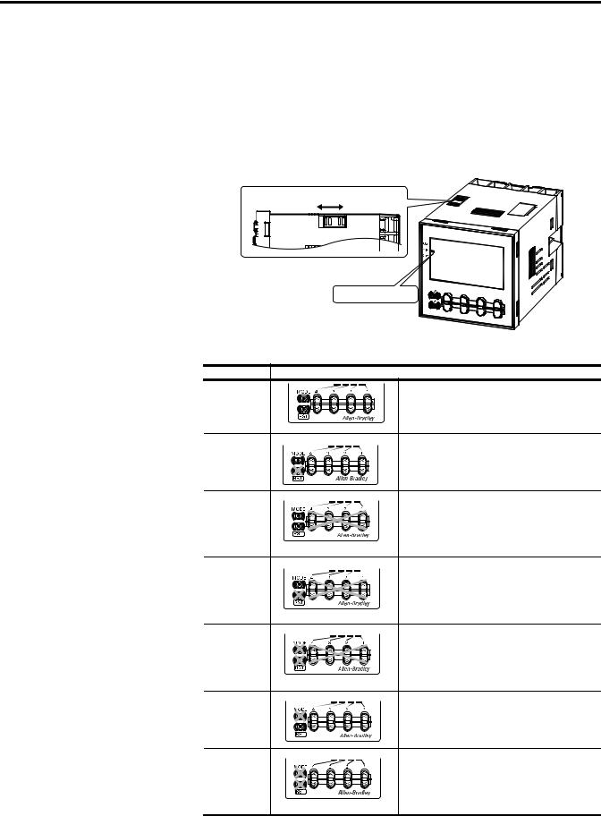
Key Protect Level (kypt)
When the key-protect switch in set to ON, it is possible to prevent setting errors by prohibiting the use of certain operation keys by specifying the key protect level (KP-1 to KP-7). The key protect indicator is lit while the key-protect switch is set to ON. Confirm the ON/OFF status of the key-protect switch after the 700-HX is mounted to the panel.
(See note) |
OFF |
ON |
Note: Factory-set to OFF |
||
|
|
Key protect indicator |
Level |
Meaning |
KP-1 |
Prohibits changing the mode to timer/repeat |
(default |
cycle selection mode or function setting |
setting) |
mode. The 700-HX can only be used in run |
|
mode. |
KP-2 |
Prohibits changing the mode to timer/repeat |
|
cycle selection mode or function setting |
|
mode. The 700-HX can only be used in run |
|
mode. Also prohibits use of the reset key. |
KP-3 |
Prohibits changing the mode to timer/repeat |
|
cycle selection mode or function setting |
|
mode. The 700-HX can only be used in run |
|
mode. Also prohibits use of the up and down |
|
keys. |
KP-4 |
Prohibits changing the mode to timer/repeat |
|
cycle selection mode or function setting |
|
mode. The 700-HX can only be used in run |
|
mode. Also prohibits use of the reset, up and |
|
down keys. |
KP-5 |
Prohibits changing the mode to timer/repeat |
|
cycle selection mode or function setting |
|
mode. The 700-HX can only be used in run |
|
mode. Also prohibits use of any operation |
|
keys. |
KP-6 |
Prohibits changing the mode to timer/repeat |
|
cycle selection mode or function setting |
|
mode. The 700-HX can only be used in run |
|
mode. Also prohibits use of the mode key. |
KP-7 |
Prohibits changing the mode to timer/repeat |
|
cycle selection mode or function setting |
|
mode. The 700-HX can only be used in run |
|
mode. Also prohibits use of mode and reset |
|
keys. |
Publication 700-UM002B-EN-D - June 2010
3-4 Functions
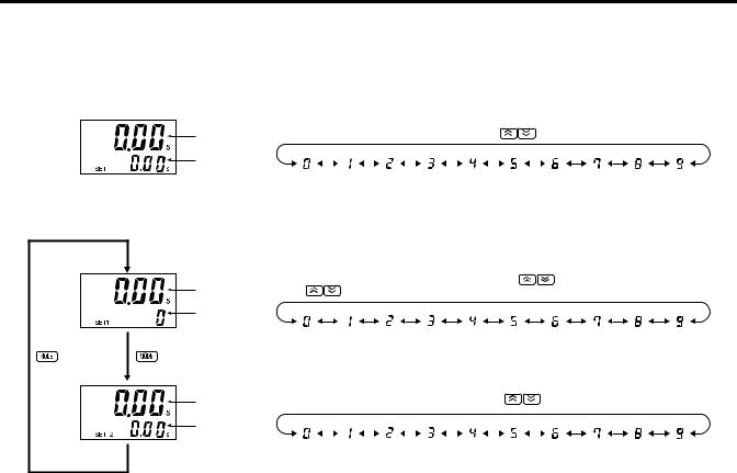
Operation in Run Mode
When Output Mode Is Not Z
Present value |
Set each digit for the set value using the corresponding |
|
keys. |
||||||||||
|
|
|
|
|
|
|
|
|
|
|
|
|
|
Set value |
|
|
|
|
|
|
|
|
|
|
|
|
|
When Output Mode Z Is Selected
Present value |
Set each digit for the ON duty ratio using the corresponding |
keys. |
|
(The |
keys for the 4th digit cannot be used.) |
|
|
ON duty ratio
Present value |
Set each digit for the cycle time using the corresponding |
|
keys. |
||||||||||
|
|
|
|
|
|
|
|
|
|
|
|
|
|
Cycle time |
|
|
|
|
|
|
|
|
|
|
|
|
|
|
|
|
|
|
|
|
|
|
|
|
|
|
|
Present Value and Set Value
These items are displayed when the power is turned ON. The present value is displayed in the main display and the set value is displayed in the sub-display. The values displayed will be determined by the settings made for the time range and the timer mode in function setting mode.
Present Value and ON Duty Ratio (Output Mode = Z)
The present value is displayed in the main display and the ON duty ratio is displayed in the sub-display. “SET1” lights at the same time.
Set the ON duty ratio used in ON/OFF-duty adjustable Repeat Cycle (Z) as a percentage.
If a cycle time is set, cyclic control can be performed in ON/OFF-duty adjustable Repeat Cycle simply by changing the ON duty ratio.
Present Value and Cycle Time (Output Mode = Z)
The present value is displayed in the main display and the cycle time is displayed in the sub-display. “SET2” lights at the same time.
Set the cycle time used in ON/OFF-duty adjustable Repeat Cycle (Z).
Publication 700-UM002B-EN-D - June 2010
 Loading...