


 Loading...
Rockwell Automation 2706-P42R, 2706-P42C, 2706-P43R, 2706-P43C, 2706-P44R User Manual [en, de, es, fr, it]
...Installation Instructions
InView Marquee Message Display
(Catalog Number 2706-P4x, 2706-P7x)
Inside... |
|
English Section ..................................................................................................... |
3 |
Français............................................................................................................... |
23 |
Deutscher Abschnitt ........................................................................................... |
43 |
Sezione italiana .................................................................................................. |
63 |
Sección de español............................................................................................. |
83 |
Seção em Português ......................................................................................... |
103 |
Publication 2706-IN006E-MU-P

English Section
Introduction
Wiring and Safety
Guidelines
Installation Instructions
InView Marquee Message Display
These instructions show how to change the serial address and how to mount InView series signs with NEMA Types 4, 4X, and 12 enclosures. These signs are intended for indoor use only. Type 4 enclosures are intended to provide a degree of protection against windblown dust and rain, splashing water, and hose-directed water. Type 4X enclosures are intended to provide a degree of protection against corrosion, windblown dust and rain, splashing water, and hose-directed water. Type 12 enclosures are in a sealed case that is, dust free, gasketing, and spray down resistant.
Install the InView display conforming to NFPA 70E, Electrical Safety Requirements for Employee Workplaces. In addition to the NFPA general guidelines, refer to the following:
Careful cable routing helps minimize electrical noise. Route incoming power to the module by a separate path from the communication cables.
Do not run communications wiring and power wiring in the same conduit!
Where communication and wire paths must cross, make their intersection perpendicular.
Grounding helps limit the effects of noise due to electromagnetic interference (EMI). To avoid problems caused by EMI, properly ground all equipment and use shielded cables.
|
Power wiring must be in accordance with Class I, |
|
IMPORTANT |
||
Class II and Class III Division 2 wiring methods |
||
|
||
|
||
|
(Articles 501-4(b), 502-4(b) and 503-3(b) of the |
|
|
National Electrical Code, NFPA70) and in |
|
|
accordance with the local authority having |
|
|
jurisdiction. |
|
|
|
Publication 2706-IN006E-EN-P

2 InView Marquee Message Display
Changing the Serial
Address
Checkout Procedure
A serial address for an InView sign is a number from 1 to 254 in hexadecimal (01 to FE). All signs leave the factory with a default address of 1 or 01.
The serial address is set in the messaging software and downloaded to the display with the InView applications.
After installing a sign according to the Electrical and Mounting Instructions, make sure the sign is installed properly by applying power to it. The following information should be displayed on the sign:
•firmware part number and version letter (e.g., xxxx),
•amount of RAM in the sign, (e.g., 256K), and
•serial address of the sign (a number from 01 to FE or from 1 to 254).
Electrical Connections |
Connecting the power wires |
|
2706-P42, 2706-P43 and |
|
|
2706-P44 |
|
|
|
Hazardous voltage. Contact with high voltage may |
|
|
|
|
|
ATTENTION |
|
|
cause death or serious injury. Always disconnect |
|
|
|
|
|
! |
power to sign prior to servicing. |
|
|
|
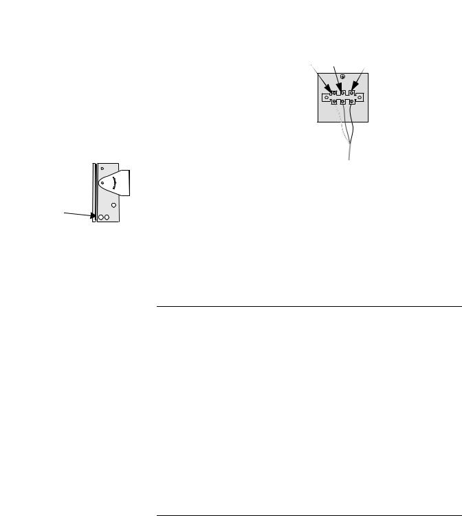
Hole plugs, left, removed
Hole plugs, top, removed
Wing nuts for hole plugs
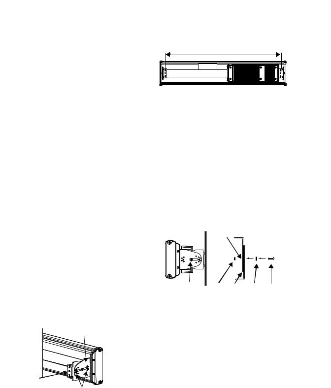
1.Remove the power supply cover by unscrewing its 6 screws. Save the screws for a later step.
2.It is recommended that you install power and serial wires at the bottom of the power supply enclosure. However, to accommodate power or serial wire installation at the top of the enclosure, you may want to remove the left or right conduit hole plug from the top of the enclosure by removing its wing nut inside the enclosure. Save the hole plug for a later step.
Publication 2706-IN006E-EN-P

InView Marquee Message Display |
3 |
|
|
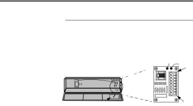
3.Insert the power wires through the left conduit hole on either the top or the bottom of the sign. The bottom conduit hole is recommended to reduce noise from power wires crossing serial wires.
TIP |
Use watertight conduit connectors only. |
|
Flexible conduit should be used. |
||
|
||
|
Internal serial wires
Insert the power wires into one of
Internal wiring for |
these |
|
conduits. |
||
power supply |
||
|
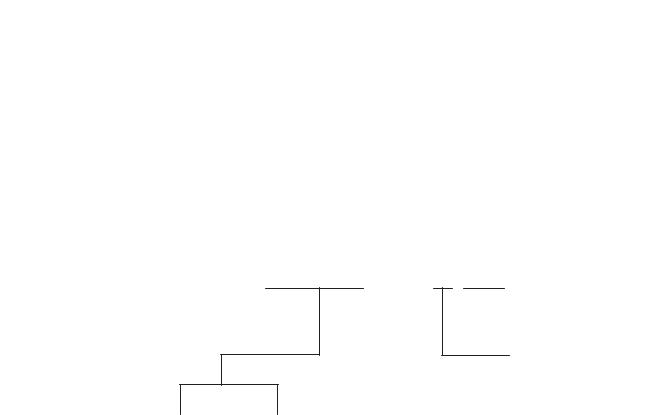
4.Strip the wires back 1/4”. Connect the incoming electrical wires.
Be sure to place the wires so they are not caught by screws when replacing the power supply cover, and also so they do not interfere with fan operation.
Ground
Line |
|
Neutral |
|
|
GREEN |
||
(Hot) |
|
||
w/ |
(Line 2): |
||
|
Hot (Line 1)
H N
Ground
Neutral (Line 2)
100 – 240 VAC
@ 50/60 Hz
5.Insert the serial wires through the right conduit hole on either the top or the bottom of the sign.
Insert the
 serial wires
Publication 2706-IN006E-EN-P

4 InView Marquee Message Display
TIP |
TB1 can be used for incoming serial connection for |
|
RS-232 or RS-485. The full pinout diagram is shown |
||
|
||
|
||
|
below. |
TB1 
|
|
|
TB1 - Full |
|
|
1. |
GND |
|
|
5. |
RS-485(+) |
|
|
|
|
|
|
2. |
+5V |
|
|
6. |
RS-485(-) |
|
|
|
|
|
|
3. |
RS-232 |
TX |
|
7. |
NC |
|
|
|
|
|
|
4. |
RS-232 |
RX |
|
8. |
SHIELD |
|
|
|
|
|
|
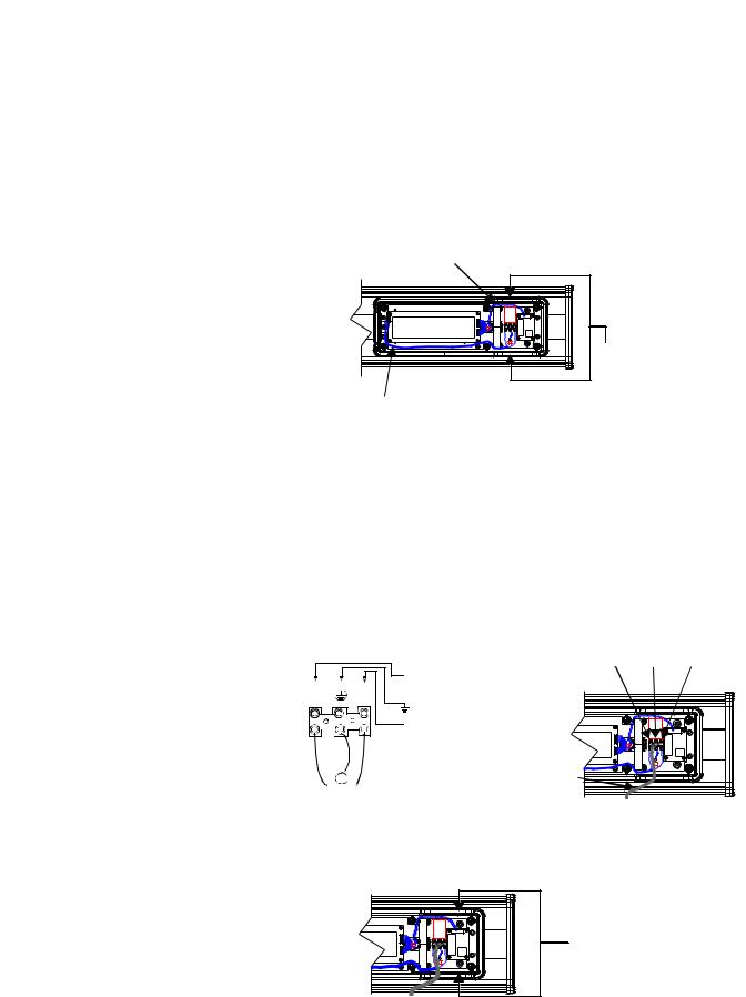
9.Connect the incoming serial wires.
TB1 can be used for incoming RS-232 or RS-485 serial connection. They cannot be connected at the same time. RS-485 is recommended to reduce undesirable electrical interference.
TB1
 Incoming serial

 wires
wires
8 |
7 |
6 |
5 |
4 |
3 |
2 |
1 |
TIP |
Be sure to place the wires so they are not caught by |
|
screws when replacing the power supply cover, and |
||
|
||
|
||
|
also so they do not interfere with fan operation. |
|
|
TB1 - RS-232 |
|
1. |
GND |
|
5. NC |
|
|
|
|
2. |
NC |
|
6. NC |
|
|
|
|
3. |
RS-232 TX |
|
7. NC |
|
|
|
|
4. |
RS-232 RX |
|
8. NC |
|
|
|
|
|
|
TB1 - RS-485 |
|
|
1. |
NC |
|
5. |
RS-485(+) |
|
|
|
|
|
2. |
NC |
|
6. |
RS-485(-) |
|
|
|
|
|
3. NC |
|
7. |
NC |
|
|
|
|
|
|
4. NC |
|
8. |
SHIELD |
|
|
|
|
|
|
Publication 2706-IN006E-EN-P
InView Marquee Message Display |
5 |
|
|
P1
Incoming  serial wires
Mounting Instructions 2706-P42, 2706-P43 and 2706-P44
9.P1 can be used for incoming RS-232 only, although it is optional and not recommended. P1 is intended for RS-232 application downloads and RS-485 terminating resistor connection. See publication 2706-IN007 for more information on RS-485 termination.
TIP |
Be sure to place the wires so they are not caught by |
|
screws when replacing the power supply cover, and |
||
|
||
|
||
|
also so they do not interfere with fan operation. |
10.To maintain NEMA compliance and to prevent EMI emissions, install hole plugs in any open conduit holes in the power supply enclosure. If needed, there is an extra hole plug supplied in addition to any hole plugs removed in Step 2 on page 2.
11.Replace the power supply cover using the 6 screws from when thecoverwasremoved.(RefertoStep1onpage2.)Torquethescrews to 2.7 Nm (24 in-lb).
12.Connect the power cable to a power source.
TIP |
Only qualified personnel should install the InView |
|
signs. |
||
|
||
|
||
|
InView signs are for indoor use only and should not |
|
|
be continuously exposed to direct sunlight. |
|
|
Mounting hardware that is used to hang or suspend |
|
|
signs must be capable of supporting at least 4 times |
|
|
the total weight of any/all signs mounted together. |
|
|
For integrity of the case, do not drill holes in or |
|
|
modify the case. |
Before mounting a sign, remove power from the sign.
Publication 2706-IN006E-EN-P
6 InView Marquee Message Display
 Remove
  these screws.
WARNING
Hazardous voltage. Contact with high voltage may cause death or serious injury. Always disconnect
!power to sign prior to servicing.
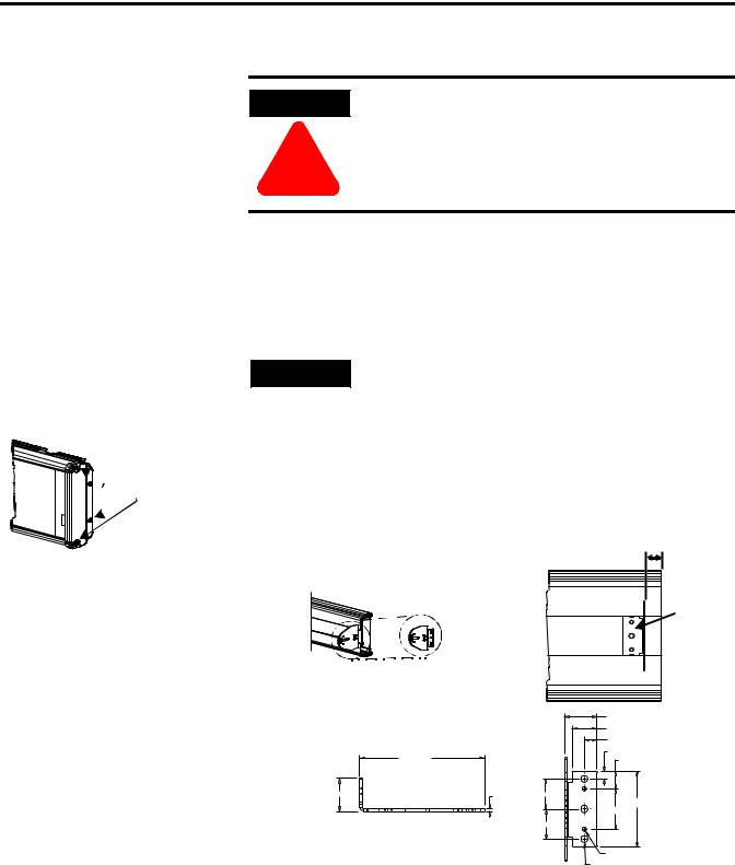
Wall Mounting
TIP |
Remove only one end cap at a time. |
|
1.Remove the 4 screws and the end cap from one end of the sign.
2.Slide one of the wall mounting brackets onto the back of the sign until it is approximately 0.5 in. away from the end of the sign.
|
0.5” |
|
Wall mounting |
Wall |
|
bracket |
||
mounting |
||
|
||
|
bracket |
|
|
|
33.13 (1.30) |
|
|
|
25.40 (1.00) |
|
|
|
12.70 (0.50) |
|
|
|
7.62 (0.30) |
|
127 (5.00) |
|
17.65 (0.70) |
|
|
|
|
33.13 (1.305) |
|
2.65 (0.105) |
30.35 (1.195) |
|
|
|
75.95 (2.99) |
|
|
|
40.64 (1.60) |
|
|
|
30.35 (1.195) |
|
|
|
4.04 (0.159) 1032 UNC-2B 2 Holes |
|
|
|
7.11 (0.280) Thru 3 Holes |
Publication 2706-IN006E-EN-P

InView Marquee Message Display |
7 |
|
|
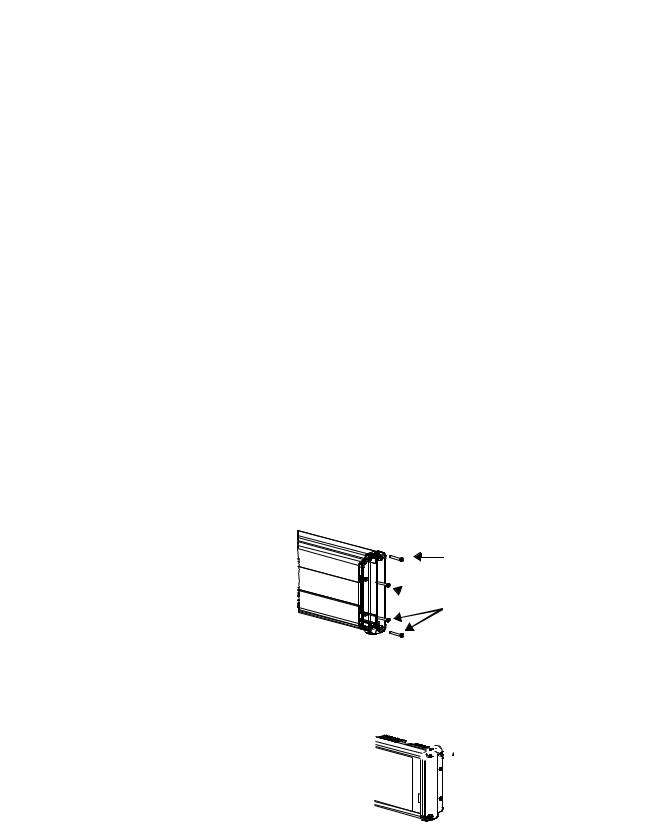
Phillips screws go here.
Fasten


 these screws.
3.Use two 10-32 x 1/4 Phillips screws (supplied) to secure the wall mounting bracket to the back of the sign. Torque the screws to 2.7 Nm (24 in-lb).
4.Replace the end cap using the 4 screws removed in Step 1 above. Torque the screws to 2.7 Nm (24 in-lb).
5.Repeat Steps 1 to 4 for the other end of the sign. Distances between the bracket holes, center-to-center, should be approximately:
37 in (94 cm) for 2706-P42 and
72.2in (183 cm) for 2706-P43
6.Attach the two remaining wall mounting brackets to a wall so that they align with the brackets on the sign.
TIP |
Do NOT install the sign directly to drywall or |
|
plaster-board. The sign must be fastened to a wall |
||
|
||
|
||
|
capable of supporting at least four times the weight |
|
|
of the sign. |
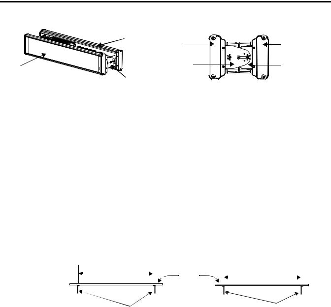
7.Connect the mounting brackets on each end of the sign together using a 5/16 Phillips screw and a 5/16 washer through the mounting holes, as shown below, securing with a 5/16 nut. Do not tighten the nut at this time.
Side view |
Top view |
|
Mounting |
|
holes |
Screw and |
Nut Brackets Washer Screw |
washer through |
|
mounting holes |
|
Publication 2706-IN006E-EN-P

8 InView Marquee Message Display
8. Match the alignment holes of the brackets on the sign with the
Mounting bracket |
alignment holes of the brackets on the wall so that the sign is at |
|
on the sign |
||
the desired viewing angle. |
||
|
|
TIP |
The second mounting bracket is shown here for |
|
Mounting |
illustration only. It is actually mounted to the wall. |
||
|
bracket on the |
Alignment holes |
|
wall |
||
|
9.Fasten the mounting brackets together using two 10-32 x 3/4 Phillips screws, two 10-32 washers, and two 10-32 lock nuts through selected alignment holes on each end of the sign.
Torque to 2.7 Nm (24 in-lb).
Lock |
|
nuts |
10. Tighten the 5/16 nuts in the mounting holes. (See Step 7). |
Washers |
Torque to 2.7 Nm (24 in-lb). |
Phillips |
|
screws |
|
Publication 2706-IN006E-EN-P

InView Marquee Message Display |
9 |
|
|
Remove  this screw.
Ceiling Mounting
1.Remove one screw from the top of the end cap.
2.Line up a ceiling bracket with the top hole on the sign’s end cap so the bracket fits in the indentation. There are left and right ceiling brackets. Use the one that fits with the screw hole’s countersunk side facing out. Secure the ceiling bracket with the screw removed in Step 1. Torque the screws to 2.7 Nm
(24 in-lb).
Screw hole Screw
Ceiling
 bracket mounted to
end cap.
Ceiling bracket
3.Repeat steps 1 and 2 for the other end of the sign.
4.Use chains (not supplied) to hang the sign from a ceiling.
TIP |
Use chains capable of supporting 4 times the total |
|
weight of the sign(s). |
||
|
||
|
TIP |
The hole you select in the ceiling bracket for the |
|
chain determines the angle at which the sign hangs. |
||
|
||
|
Publication 2706-IN006E-EN-P
10 InView Marquee Message Display
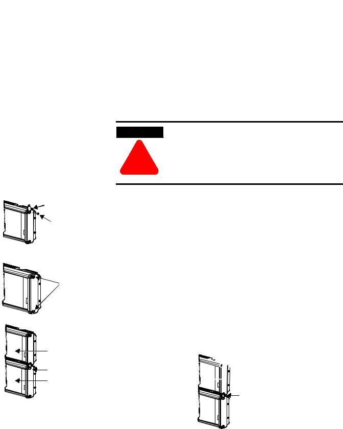
Stacking bracket
 Screw
Screw
Remove  these
these
screws.
Next sign
Stacking bracket
Bottom sign
Stacking
TIP |
Up to 4 signs can be hung together vertically |
|
(“stacked”). Mounting system for stack mounting |
||
|
||
|
||
|
must support a minimum of four times the total |
|
|
weight of all signs being stacked. |
WARNING
Possible crush hazard. Do not stack more than 4 signs. Otherwise signs may fall causing serious injury
!or death.
1.Remove the top screw from each end cap of the bottom sign, as shown in Step 1 of the Ceiling Mounting instructions on page 9.
2.Using the screw removed in Step 1, screw a stacking bracket to each end cap, countersunk side out. Torque to 2.7 Nm (24 in-lb).
3.Remove the top and bottom screws from each end of the remaining signs.
4.For each end of the signs, secure the stacking bracket from the bottom sign to the next sign using one of the screws removed in Step 3. Torque to 2.7 Nm (24 in-lb).
5.Secure a ceiling bracket to the top of each end cap on the top sign, using Step 2 of the Ceiling Mounting instructions on page 9.
Ceiling bracket Top sign
Stacking bracket
Publication 2706-IN006E-EN-P
InView Marquee Message Display |
11 |
|
|
6.Use a chain (not supplied) to hang the signs from the ceiling, following the notes in Step 4 of Ceiling Mounting instructions on page 9.
Back-to-Back Mounting
TIP |
Remove only one end cap at a time for each sign. |
|
|
|
|
1.Attach a mounting bracket on each end of the signs and replace the end caps, following Steps 1 to 4 of the Wall mounting instructions. However, replace only the bottom three screws for each end cap. Torque the screws to 2.7 Nm (24 in-lb). Do this step for each end of both signs.
TIP |
Do NOT fasten the top screws to the end caps. The |
|
top screws will be used to fasten the ceiling |
||
|
||
|
||
|
mounting brackets to the end caps in the next step. |
Do NOT fasten this screw to the end cap.
 Fasten these three screws to each end cap.
2.Attach ceiling mounting brackets to all the end caps following Step 2 of the ceiling mounting instructions. Torque the screws to 2.7 Nm (24 in-lb).


 Ceiling mounting bracket
3.Match the signs together back-to-back. Connect them together following Steps 7 through 10 of the Wall Mounting instructions on page 7.
Publication 2706-IN006E-EN-P
12 InView Marquee Message Display
|
Second |
First |
Second |
|
sign |
||
|
sign |
sign |
|
|
|
||
First |
|
First |
Second |
|
mounting |
mounting |
|
sign |
Mounting |
bracket |
bracket |
|
|
|
|
|
brackets |
|
|
4. Use chains (not supplied) to hang the signs from the ceiling.
TIP |
Use chains capable of supporting 4 times the total |
|
weight of the signs. |
||
|
||
|
Mounting Instructions 2706-P72 and 2706-P74 series NEMA 4 and 4x models
1.Attach the two sign brackets to a wall, ceiling, or other surface.
Be sure to place the brackets so the bracket flanges face appropriately as shown below. Mount the brackets the following distance apart (measured from the center of the mounting holes in each bracket):
Mounted so flanges are hidden behind the sign |
|
Mounted so flanges show on the sides of the sign |
|||||
|
|
|
|
||||
2706-P72CNx: 41.25 in (104.8 cm) |
Wall |
|
2706-P72CNx: 43.5 in (110.5 cm) |
|
|||
|
|
|
|
||||
|
|
|
|
|
|
|
|
2706-P74CNx: 65.25 in (165.8 cm) |
|
|
|
|
|
||
or |
|
2706-P74CNx: 67.5 in (171.4 cm) |
|
||||
|
|
|
|
||||
ceiling
Sign brackets, facing |
Sign brackets, facing |
|
out from the sign |
||
in behind the sign |
||
|
TIP |
Do NOT install the sign directly to drywall or |
|
plasterboard. The sign must be fastened to a surface |
||
|
||
|
||
|
capable of supporting at least four times the weight |
|
|
of the sign. |
2.Mount the sign on the sign brackets using the two large hex bolts supplied.
Publication 2706-IN006E-EN-P

InView Marquee Message Display |
13 |
|
|
184.15
(7.25 REF)
30.48 (1.20)
Ceiling
(0.50 REF) |
End view, |
(0.36 TYP) |
ceiling-mounted |
|
 Hex bolt
Hex bolt End view,
Wall wall-mounted
139.70 (5.50)
69.85
(2.75)
19.05
(0.75)
8.74 x 12.70 (0.344 x 0.50) OBRound Slot (3 Places)
3.Tilt the sign to select a viewing angle. To hold the sign in place, screw a Phillips screw (supplied) through one of the small holes on each bracket into the screw hole in the sign case.
Phillips screw |
Ceiling |
Phillips screw |
End view, |
End view, |
|
wall-mounted |
ceiling-mounted |
|
Wall |
|
|
TIP |
Keep a minimum 1.0-inch (2.54 cm) clearance on all |
|
sides of the sign for adequate ventilation. |
||
|
||
|
Electrical Connections 2706-P72 and 2706-P74
WARNING
!
Hazardous voltage. Contact with high voltage may cause death or serious injury. Always disconnect power to sign prior to servicing.
1.Open the front of the sign case by turning the quarter-turn latches to the left with a large screwdriver. (On the 2706-P72CNx, there are 3 quarter-turn latches; on the 2706-P74CNx there are 4.) Carefully let the front of the case drop forward.
Publication 2706-IN006E-EN-P

14 InView Marquee Message Display
Front view, closed
Quarter-turn latches on an 2706-P74 sign
|
|
Serial |
Power line |
|
Front view, open |
Power supply |
filter |
||
connection |
||||
|
Power
connection
 Electrical
opening
 Serial device opening
2.Feed electrical cable through 1” water-tight conduit, the outside end of the connector (supplied), the electrical opening in the sign case, and then through the inside end of the connector. Screw the inside and outside ends of the connector together until water-tight.
|
Front view |
Rubber gasket |
Right-end |
Conduit |
|
view |
|
|
|
Sign case, |
Connector, |
|
outside end |
|
|
inside |
|
Electrical opening |
Connector nut, with teeth |
|
|
|
facing the sign case |
3.Striptheelectricalwiresback1/4”.Connectthewiresbyscrewingthe end of each wire into the power connection.
Publication 2706-IN006E-EN-P
InView Marquee Message Display |
15 |
|
|
Right-end view
Serial device hole plug/opening
Line |
Ground |
||
|
|
Neutral |
|
|
|
|
|
(Hot) |
GREEN |
||
w/ |
|
(Line 2): |
|
|
|
||
|
1 LINE |
GROUND |
OR 2 LINE NEUTRAL |
Power connection |
|
|
|
|
1 LINE |
GROUND |
OR 2 LINE NEUTRAL |
|
208 - 240 VAC INPUT |
||
4.If the sign is to be used with serial communications, remove one or both of the hole plugs from the lowest holes on the right end of the sign case. Otherwise, proceed to Step 6.
TIP |
TB1 can be used for incoming serial connection for |
|
RS-232 or RS-485. The full pinout diagram is shown |
||
|
||
|
||
|
below: |
|
|
|
TB1 - Full |
|
|
|
|
|
|
|
|
1. |
GND |
|
|
5. |
RS-485(+) |
|
|
|
|
|
|
2. |
+5V |
|
|
6. |
RS-485(-) |
|
|
|
|
|
|
3. |
RS-232 |
TX |
|
7. |
NC |
|
|
|
|
|
|
4. |
RS-232 |
RX |
|
8. |
SHIELD |
|
|
|
|
|
|
9.Connect the incoming serial wires per pinout.
TB1 can be used for incoming RS-485 or RS-232 serial connection. They cannot be connected at the same time.
RS-485 is recommended to reduce undesirable electrical interference.
|
|
TB1 - RS-485 |
|
|
|
|
|
|
|
1. |
NC |
|
5. |
RS-485(+) |
|
|
|
|
|
2. |
NC |
|
6. |
RS-485(-) |
|
|
|
|
|
3. NC |
|
7. |
NC |
|
|
|
|
|
|
4. NC |
|
8. |
SHIELD |
|
|
|
|
|
|
Publication 2706-IN006E-EN-P
16 InView Marquee Message Display
|
|
TB1 - RS-232 |
|
1. |
GND |
|
5. NC |
|
|
|
|
2. |
NC |
|
6. NC |
|
|
|
|
3. |
RS-232 TX |
|
7. NC |
|
|
|
|
4. |
RS-232 RX |
|
8. NC |
|
|
|
|
|
1 |
|
2 |
TB1 |
3 |
4 |
|
|
5 |
|
6 |
|
7 |
|
8 |
Controller Board |
|
P1 can be used for incoming RS-232 only, although it is optional and not recommended.P1 is intended for RS-232 application downloads and RS-485 terminating resistor connection. See publication 2706-IN007 for more information on RS-485 termination.
9.Carefully close the front of the sign case and turn the quarter-turn latches to the right with a large screwdriver.
Publication 2706-IN006E-EN-P

|
|
InView Marquee Message Display |
17 |
|
|
|
|
|
|
Specifications |
|
|
|
|
Table A |
|
|
|
|
|
|
|
|
|
|
2706-P43R(2) |
2706-P42R(1), 2706-P42C(1) |
2706-P72CNx(1) |
|
|
2706-P43C(2) |
2706-P44R(2), 2706-P44C(2) |
2706-P74CNx(2) |
|
Display |
|
|
|
|
|
|
|
|
|
Display Type |
LED matrix: Red (R) or |
LED matrix: Red (R) or |
LED matrix: Tri-Color (C) |
|
|
Tri-Color (C) |
Tri-Color (C) |
|
|
|
|
|
|
|
Display Size (W x H) |
68.1 x 4 in (173.2 x 10.2 cm)(2) |
36 x 4.8 in (81.4 x 12.2 cm)(1) |
36 x 7.2 in (91.4 x 18.3 cm)(1) |
|
|
|
72 x 4.8 in (182.8 x 12.2 cm)(2) |
60 x 7.2 in (152.4 x 18.3 cm)(2) |
|
Display Array |
120 x 7 pixels |
120 x 16 or 240 x 16 pixels |
120 x 24 or 200 x 24 pixels |
|
|
|
|
|
|
Center to Center Pixel Spacing |
0.57 in |
0.3 in |
0.3 in |
|
(Pitch) |
|
|
|
|
|
|
|
|
|
Number of Lines |
1 |
1 or 2 |
1 to 4 |
|
|
|
|
|
|
Lines of Text/Character Height/ |
1 line/4 in/20 char(2) |
1 line/4.8 in/12(1) or 24(2) |
1 line/7.2 in/12(1) or 20(2) |
|
Minimum Characters per Line |
|
2 line/2.1 in/20(1) or 40(2) |
2 line/3.0 in/20(1) or 33(2) |
|
|
|
|
3 line/2.1 in/20(1) or 33(2) |
|
|
|
|
4 line/1/5 in/24(1) or 40(2) |
|
Character Set |
Standard and Extended ASCII |
Standard and Extended ASCII |
Standard and Extended ASCII |
|
|
|
|
|
|
Approximate Viewing Distance |
60m (200 ft) |
60m (200 ft) |
100m (350 ft) |
|
|
|
|
|
|
Electrical and Environmental |
|
|
|
|
|
|
|
|
|
Input Voltage |
100 to 240V ac; 50/60 Hz |
100 to 240V ac; 50/60 Hz |
100 to 240V ac; 50/60 Hz |
|
|
|
|
|
|
Current Draw |
1A at 100V ac; 0.5A at 240V ac |
1A at 100V ac; 0.5A at 240V ac |
2A at 100V ac; 1.5A at 240V ac |
|
|
|
|
|
|
Operating Temperature |
+0°C to +50°C (+32°F to +122°F) |
+0°C to +50°C (+32°F to +122°F) |
+0°C to +50°C (+32°F to +122°F) |
|
|
|
|
|
|
Humidity |
5 to 95% noncondensing |
5 to 95% noncondensing |
5 to 95% noncondensing |
|
|
|
|
|
|
Ratings |
NEMA 12 |
NEMA 12 |
NEMA 4, 4X |
|
|
|
|
|
|
Certifications |
ETL approved; CE marked |
ETL approved; CE marked |
ETL approved; CE marked |
|
|
|
|
|
|
Enclosure Approximate Weight |
40 lbs (18 kg) |
28 lbs (12.7 kg) or |
60 lbs (27.2 kg) or |
|
|
|
50 lbs (22.7 kg) |
80 lbs (36.3 kg) |
|
|
|
|
|
|
Enclosure Dimensions |
71.9 x 5.5 x 7.88 in(2) |
40.38 x 5.5 x 7.88 in(1) |
42.25 x 6 x 13.75 in(1) |
|
(W x D x H) |
(182.7 x 13.97 x 20.0 cm) |
(102.57 x 13.97 x 20.0 cm) |
(107.32 x 15.24 x 34.93 cm) |
|
|
|
76.38 x 5.5 x 7.88 in(2) |
66.25 x 6 x 13;.75 in(2) |
|
|
|
(194 x 13.97 x 20.0 cm) |
(168.28 x 15.24 x 34.93 cm) |
|
|
|
|
|
|
(1)Display is available in short format (3 feet).
(2)Display is available in long format (6 feet).
Publication 2706-IN006E-EN-P

18 InView Marquee Message Display
Temperature Protection in
NEMA-Rated Enclosures
InView P42, P43, P44, P72, and P74 signs have automatic temperature controls that help to protect the sign from damage when the internal temperature of the sign is too hot to continue normal operation.
•If the internal temperature of the sign reaches a pre-determined “dimming point”, the LED output from the sign is forced into a 50 percent reduced power mode, effectively dimming the brightness of LED output by about 50 percent.
•If the internal temperature of the sign continues to increase, another sensing circuit will execute an automatic shut down to protect the sign from damage. The LED output from the sign is turned off.
•The dimming and shutdown points are listed in the table below. Once the temperature drops below the auto-shutdown threshold, the LED output is turned on at the dimming level. Once the temperature drops below the dimming threshold, auto-dimming is disabled and the LED brightness is back to 100 percent.
Table B
Model |
Enclosure |
Dimming Point |
Auto-Shutdown On |
|
|
|
|
2706-P42, 2706-P44 |
NEMA 12 |
55°C (131°F) |
70°C (158°F) |
|
|
|
|
2706-P43 |
NEMA 12 |
55°C (131°F) |
70°C (158°F) |
|
|
|
|
2706-P72, 2706-P74 |
NEMA 4, NEMA 4x |
55°C (131°F) |
70°C (158°F) |
|
|
|
|
TIP |
Take into account the effects of ambient temperature |
|
when evaluating mounting locations for the sign. |
||
|
||
|
||
|
You should always maintain recommended clearance |
|
|
distances around the sign and avoid poorly |
|
|
ventilated mounting locations that could be subject |
|
|
to radiation, convection, conduction or other thermal |
|
|
transfer effects. |
Publication 2706-IN006E-EN-P
InView Marquee Message Display |
19 |
|
|
Catalog Number
Explanation
|
• The 4 inch displays are available in NEMA 12 |
|
TIP |
||
only. |
||
|
||
|
||
|
• The 7 inch displays are available with the |
|
|
Standard LED pitch only. |
|
|
• The 7 inch displays are available in color only. |
2706-P 7 2 C N2
Bulletin Number
2706-P = InView
Marquee Display
|
|
|
|
|
|
|
|
|
|
|
|
|
|
|
|
|
|
|
|
Display Height |
|
Display Length |
|||||||
|
|
|
|
|
|
|
|
|
|
4 = 4 inch max display character
7 = 7 inch max display character
2 = Short Case (Appx. 3 ft) with Std LED Pitch
3 = Long Case (Appx. 6 ft) with Large LED Pitch
4 = Long Case (Appx. 6 ft) with
|
|
|
|
|
|
|
|
|
|
|
|
|
|
|
|
|
|
|
|
|
|
LED Color |
|
|
NEMA Rating |
||
|
|
|
|
|
|
|
|
C = Tri-Color |
Blank = NEMA 12 |
||||
|
R = Red |
N1 |
= NEMA 4X |
|||
|
|
|
|
N2 |
= NEMA 4 |
|
Publication 2706-IN006E-EN-P
20 InView Marquee Message Display
Important User Information Because of the variety of uses for the products described in this publication, those responsible for the application and use of this
control equipment must satisfy themselves that all necessary steps have been taken to assure that each application and use meets all performance and safety requirements, including any applicable laws, regulations, codes and standards.
The illustrations, charts, sample programs and layout examples shown in this guide are intended solely for purposes of example. Since there are many variables and requirements associated with any particular installation, Allen-Bradley does not assume responsibility or liability (to include intellectual property liability) for actual use based upon the examples shown in this publication.
Allen-Bradley publication SGI-1.1, Safety Guidelines for the Application, Installation and Maintenance of Solid-State Control
(available from your local Allen-Bradley office), describes some important differences between solid-state equipment and electromechanical devices that should be taken into consideration when applying products such as those described in this publication.
Reproduction of the contents of this copyrighted publication, in whole or part, without written permission of Rockwell Automation, is prohibited.
For More Information
Table 3 Related Publications
For |
Refer to this Document |
Pub. No. |
|
|
|
A more detailed description of |
User Manual |
2706-UM016 |
how to use your marquee display. |
|
|
|
|
|
If you would like a manual, you can:
•download a free electronic version from the internet: www.theautomationbookstore.com
•purchase a printed manual by:
–contacting your local distributor or Rockwell Automation representative
–visiting www.theautomationbookstore.com and placing your order
–calling 1.800.963.9548 (USA/Canada) or 001.330.725.1574 (Outside USA/Canada)
Publication 2706-IN006E-EN-P

Notice d'installation
Français |
Afficheur de messages InView |
Introduction |
La présente notice indique comment changer l’adresse série et |
|
comment monter les afficheurs de la série InView dans les boîtiers |
|
NEMA types 4, 4X et 12. Ces afficheurs sont destinés à une utilisation |
|
intérieure uniquement. Les boîtiers de type 4 sont conçus pour fournir |
|
une protection contre la poussière, la pluie et les projections d’eau. |
|
Les boîtiers de type 4X sont conçus pour fournir une protection contre |
|
la corrosion, la poussière, la pluie et les projections d’eau. Les boîtiers |
|
de type 12 sont des boîtiers étanches à la poussière et aux projections |
|
d’eau. |
Directives de câblage et consignes de sécurité
Installez l’afficheur InView conformément à la norme NFPA 70E (directives de sécurité électrique sur le lieu de travail). Outre les directives générales de la NFPA (association nationale américaine de protection contre l’incendie), observez les recommandations suivantes :
Un acheminement soigné des câbles permet de réduire les parasites électriques. Acheminez le câble d’alimentation du module par un chemin différent de celui des câbles de communication.
N’acheminez pas les câbles de communication et le câble d’alimentation par le même conduit !
Si les câbles de communication doivent croiser le câble d’alimentation, faites-les se croiser perpendiculairement.
La mise à la terre permet de limiter les effets des parasites causés par les interférences électromagnétiques (EMI). Pour éviter tout problème d’interférences électromagnétiques, mettez tous les équipements à la terre et utilisez des câbles blindés.
|
Le câblage d’alimentation doit être conforme aux |
|
IMPORTANT |
||
méthodes de câblage de Classe I, Classe II et |
||
|
||
|
||
|
Classe III, Division 2 (articles 501-4(b), 502-4(b) et |
|
|
503-3(b) du Code national de l’électricité des |
|
|
Etats-Unis, norme NFPA 70) et aux réglementations |
|
|
locales en vigueur. |
|
|
|
Publication 2706-IN006E-MU-P

24 Afficheur de messages InView
Modification
de l’adresse série
L’adresse série d’un afficheur InView est un nombre hexadécimal de 1 à 254 (01 à FE). Tous les afficheurs sont livrés avec une adresse par défaut de 1 ou 01.
L’adresse série se règle dans le logiciel de messagerie et se charge ensuite dans l’afficheur avec les applications InView.
Procédure de vérification |
Après avoir installé un afficheur conformément aux directives |
|
électriques et de montage, assurez-vous qu’il est correctement installé |
|
en le mettant sous tension. Les informations suivantes doivent être |
|
affichées : |
|
• le numéro du firmware et la lettre indiquant la version |
|
(ex. : xxxx) ; |
|
• la quantité de mémoire RAM de l’afficheur (ex. 256K) ; |
|
• l’adresse série de l’afficheur (nombre entre 01 et FE ou entre 1 et |
|
254). |
Connexions électriques |
Connexion des câbles d’alimentation |
des afficheurs 2706-P42, |
|
2706-P43 et 2706-P44 |
|
|
Bouchons de protection gauches
ATTENTION |
Tension dangereuse. Tout contact avec une tension |
|
élevée peut entraîner la mort ou des blessures |
||
|
||
! |
graves. Déconnectez toujours l’alimentation de |
|
l’afficheur avant toute opération de maintenance. |
||
|
|
Bouchons de protection supérieurs
Ecrous à ailettes pour bouchons de protection
1.Retirez le capot de l’alimentation en dévissant ses 6 vis. Mettez les vis de côté : vous les réutiliserez plus tard.
2.Il est recommandé d’installer les câbles d’alimentation et série dans la partie inférieure du boîtier de l’alimentation. Cependant, si vous voulez installer ces câbles dans la partie supérieure, retirez le bouchon de protection gauche ou droit de la partie supérieure du boîtier en ôtant son écrou à ailette. Mettez le bouchon de côté : vous le réutiliserez plus tard.
Publication 2706-IN006E-MU-P
Afficheur de messages InView |
25 |
|
|
3.Insérez les câbles d’alimentation par le conduit supérieur ou inférieur gauche de l’afficheur. Il est recommandé d’utiliser le conduit inférieur pour minimiser les parasites dus au passage des câbles d’alimentation près des câbles série.
REMARQUE |
Utilisez uniquement des raccords de conduit |
|
étanches. Il est préférable d’utiliser des |
||
|
||
|
||
|
conduits flexibles. |
|
Câbles série internes |
||
Insérez les câbles d’alimentation dans l’un de ces conduits
Câblage interne de l’alimentation
4.Dénudez les câbles sur 6 mm. Connectez les câbles électriques.
Veillez à positionner les câbles de telle sorte qu’ils ne soient pas accrochés par les vis lorsque vous remettrez le capot de l’alimentation en place et qu’ils n’empêchent pas le bon fonctionnement du ventilateur.
Ligne |
Terre |
Neutre |
|
||
(tension) |
VERT avec (ligne 2) : |
|
NOIR |
jaune |
BLANC |
|
||
Hot (Line 1)
H N
Ground
Neutral (Line 2)
100-240 V c.a. à 50/60 Hz
5.Insérez les câbles série par le conduit supérieur ou inférieur droit de l’afficheur.
Insérez les câbles série dans l’un de ces conduits
Publication 2706-IN006E-MU-P

26 Afficheur de messages InView
Bornier
TB1 
Bornier
TB1
 Câbles série

 entrants
8 |
7 |
6 |
5 |
4 |
3 |
2 |
1 |
REMARQUE |
Le bornier TB1 peut être utilisé pour la connexion |
|
série avec RS-232 ou RS-485. Le diagramme complet |
||
|
||
|
||
|
du brochage est indiqué ci-dessous. |
|
|
|
|
|
TB1 - Complet |
1. |
TERRE |
|
5. |
RS-485(+) |
|
|
|
|
|
2. |
+5 V |
|
6. |
RS-485(-) |
|
|
|
|
|
3. |
RS-232 |
TX |
7. |
Pas de connexion |
|
|
|
|
|
4. |
RS-232 |
RX |
8. |
BLINDAGE |
|
|
|
|
|
6.Connectez les câbles série entrants.
Le bornier TB1 peut être utilisé pour l’entrée des connexions série RS-232 ou RS-485 mais pas pour les deux simultanément. Il est recommandé d’utiliser RS-485 pour réduire les parasites électriques.
REMARQUE |
Veillez à positionner les câbles de telle sorte qu’ils ne |
|
soient pas accrochés par les vis lorsque vous |
||
|
||
|
||
|
remettrez le capot de l’alimentation en place et qu’ils |
|
|
n’empêchent pas le bon fonctionnement du |
|
|
ventilateur. |
|
|
|
|
|
TB1 - RS-232 |
1. |
TERRE |
|
|
5. |
Pas de connexion |
|
|
|
|
|
|
2. |
Pas de connexion |
|
6. |
Pas de connexion |
|
|
|
|
|
|
|
3. |
RS-232 |
TX |
|
7. |
Pas de connexion |
|
|
|
|
|
|
4. |
RS-232 |
RX |
|
8. |
Pas de connexion |
|
|
|
|
|
|
|
|
|
|
|
|
|
|
|
TB1 - RS-485 |
|
|
|
|
|
|
||
1. |
Pas de connexion |
|
5. |
RS-485(+) |
|
|
|
|
|
|
|
2. |
Pas de connexion |
|
6. |
RS-485(-) |
|
|
|
|
|
|
|
3. |
Pas de connexion |
|
7. |
Pas de connexion |
|
|
|
|
|
|
|
4. |
Pas de connexion |
|
8. |
BLINDAGE |
|
|
|
|
|
|
|
Publication 2706-IN006E-MU-P

Afficheur de messages InView |
27 |
|
|
P1
Câbles série  entrants
7.P1 peut être utilisé pour la connexion RS-232 uniquement, mais cette option n’est pas recommandée. P1 est destiné aux chargements d’application RS-232 et pour la connexion de la résistance de terminaison RS-485. Voir la publication 2706-IN007 pour plus d’informations sur la terminaison RS-485.
REMARQUE |
Veillez à positionner les câbles de telle sorte qu’ils ne |
|
soient pas accrochés par les vis lorsque vous |
||
|
||
|
||
|
remettrez le capot de l’alimentation en place et qu’ils |
|
|
n’empêchent pas le bon fonctionnement du |
|
|
ventilateur. |
8.Pour être conforme à la norme NEMA et éviter les interférences électromagnétiques, installez des bouchons sur tous les conduits ouverts du boîtier de l’alimentation. Un bouchon supplémentaire vous est fourni pour le cas où les bouchons que vous avez retirés à l’étape 2, page 24, ne seraient pas suffisants.
9.Remettez le capot de l’alimentation en place à l’aide des 6 vis (voir l’étape 1, page 24). Serrez les vis avec un couple de 2,7 Nm.
10.Branchez le câble d’alimentation sur une source d’alimentation.
Instructions de montage des afficheurs 2706-P42, 2706-P43 et 2706-P44
REMARQUE |
Les afficheurs InView doivent être installés |
|
uniquement par du personnel qualifié. |
||
|
||
|
||
|
Les afficheurs InView sont destinés à une utilisation |
|
|
intérieure uniquement et ne doivent pas être exposés |
|
|
de façon continue aux rayons directs du soleil. |
|
|
Le matériel de montage utilisé pour suspendre les |
|
|
afficheurs doit pouvoir supporter au moins 4 fois le |
|
|
poids total de tous les afficheurs montés ensemble. |
|
|
Pour assurer l’intégrité du boîtier, ne percez pas de |
|
|
trous dans ce boîtier et ne le modifiez pas. |
Avant de monter un afficheur, déconnectez son alimentation.
AVERTISSEMENT
!
Tension dangereuse. Tout contact avec une tension élevée peut entraîner la mort ou des blessures graves. Déconnectez toujours l’alimentation de l’afficheur avant toute opération de maintenance.
Publication 2706-IN006E-MU-P

28 Afficheur de messages InView
 Retirez ces vis.
Les vis Phillips se placent ici
 Serrez
 ces vis
Montage sur un mur
REMARQUE |
Ne retirez qu’un capot de protection à la fois. |
|
|
|
|
1.Retirez les 4 vis et le capot de protection de l’une des extrémités de l’afficheur.
2.Glissez l’un des supports de fixation murale à l’arrière de l’afficheur et placez-le à environ 1,25 cm de l’extrémité de l’afficheur.
|
0.5” |
Support de fixation murale |
Support |
|
|
|
de fixation |
|
murale |
|
|
|
33.13 (1.30) |
|
|
|
25.40 (1.00) |
|
|
|
12.70 (0.50) |
|
|
|
7.62 (0.30) |
|
127 (5.00) |
|
17.65 (0.70) |
33.13 (1.305) |
|
2.65 (0.105) |
30.35 (1.195) |
|
|
|
|
|
|
|
75.95 (2.99) |
|
|
|
40.64 (1.60) |
|
|
|
30.35 (1.195) |
|
|
|
4.04 (0.159) 1032 UNC-2B 2 Holes |
|
|
|
7.11 (0.280) Thru 3 Holes |
3.Utilisez deux vis Phillips de 8 x 19 mm (fournies) pour fixer le support de fixation à l’arrière de l’afficheur. Serrez les vis avec un couple de 2,7 Nm.
4.Remettez le capot de protection en place à l’aide des 4 vis que vous avez retirées à l’étape 1 ci-dessus. Serrez les vis avec un couple de 2,7 Nm.
5.Répétez les étapes 1 à 4 pour l’autre extrémité de l’afficheur. L’espacement entre les trous des supports (au centre des trous) doit être d’environ :
Publication 2706-IN006E-MU-P
Afficheur de messages InView |
29 |
|
|
94 cm pour le 2706-P42
183 cm pour le 2706-P43
185,4 cm pour le 2706-P44
6.Fixezlesdeuxsupportsdefixationrestantssurunmur,enlesalignant sur les supports montés sur l’afficheur.
REMARQUE |
N’installez PAS l’afficheur directement sur une |
|
cloison sèche ou une paroi en placoplâtre. Il doit |
||
|
||
|
||
|
être fixé sur un mur capable de supporter au moins |
|
|
4 fois le poids de l’afficheur. |
7.Assemblezlessupportsdefixationsurchaqueextrémitédel’afficheur eninsérantunevisPhillipsetunerondellede8 mmdanschaquetroude fixation,commeindiquéci-dessous,quevousfixerezavecunécroude 8 mm. Ne serrez pas cet écrou pour le moment.
Vue latérale
Vis et rondelle passant par le trou de fixation
Vue supérieure
Trou de fixation
Ecrou Supports Rondelle Vis
8. Alignez les trous d’alignement des supports montés sur
Support de fixation sur l’afficheur
l’afficheur sur ceux des supports fixés au mur de manière à donner à l’afficheur l’angle de vision souhaité.
Support de fixation sur un mur
REMARQUE |
Le deuxième support de fixation n’apparaît ici qu’à |
|
des fins d’illustration. Il est en réalité monté sur le |
||
|
||
|
||
|
mur. |
Trous d’alignement
9.Fixez les supports de fixation ensemble en introduisant deux vis Phillips et deux rondelles de 8 mm dans les trous d’alignement choisis à chaque extrémité de l’afficheur, que vous fixerez avec deux contre-écrous de 8 mm. Serrez avec un couple de 2,7 Nm.
Publication 2706-IN006E-MU-P

30 Afficheur de messages InView
Contreécrous
Retirez
 cette vis
|
10. Serrez les écrous de 8 mm sur les trous de fixation (voir |
Rondelles |
l’étape 7) avec un couple de 2,7 Nm. |
Vis Phillips
Montage sur un plafond
1. Retirez une vis du haut du capot de protection.
2. Alignez un support de fixation pour plafond sur le trou supérieur du capot de protection, de manière à ce que le support s’insère dans l’encoche : il y a des supports gauche et droit. Le support à utiliser est celui qui s’adapte au trou destiné à recevoir la vis, côté renfoncé orienté vers l’extérieur. Fixez le support de fixation pour plafond avec la vis que vous avez retirée à l’étape 1. Serrez la vis avec un couple de 2,7 Nm.
Trou pour la vis |
Vis |
|
Support de fixation
 pour plafond monté sur le capot de protection
 Support de fixation pour plafond
3.Répétez les étapes 1 et 2 pour l’autre extrémité de l’afficheur.
4.Utilisez des chaînes (non fournies) pour suspendre l’afficheur au plafond.
REMARQUE
REMARQUE
Utilisez des chaînes capables de supporter 4 fois le poids total des afficheurs.
Le trou choisi pour la chaîne sur le support de fixation pour plafond détermine l’angle de suspension de l’afficheur.
Publication 2706-IN006E-MU-P
Afficheur de messages InView |
31 |
|
|
Support d’empilement
Vis
Retirez
 ces vis
Afficheur suivant
Support d’empilement
Premier afficheur
Empilement
REMARQUE |
Vous pouvez suspendre jusqu’à 4 afficheurs |
|
ensemble (« empilement »). Le système de montage |
||
|
||
|
||
|
pour les afficheurs empilés doit pouvoir supporter au |
|
|
moins 4 fois le poids total de tous les afficheurs |
|
|
empilés. |
AVERTISSEMENT Danger de chute possible. N’empilez pas plus de 4 afficheurs sinon, ils risquent de tomber et
!d’entraîner des blessures graves voire la mort.
1.Retirez la vis supérieure de chaque capot de protection du premier afficheur (celui du bas), comme indiqué à l’étape 1 de la section Montage sur un plafond, page 30.
2.A l’aide de la vis que vous avez retirée à l’étape 1, fixez un support d’empilement sur chaque capot de protection, côté renfoncé vers l’extérieur. Serrez la vis avec un couple de 2,7 Nm.
3.Retirez les vis supérieure et inférieure à chaque extrémité des autres afficheurs.
4.A chaque extrémité des afficheurs, fixez le support d’empilement de l’afficheur inférieur sur l’afficheur suivant à l’aide de l’une des vis retirées à l’étape 3. Serrez la vis avec un couple de 2,7 Nm.
5.Fixez un support de fixation pour plafond en haut de chaque capot de protection de l’afficheur du haut, en suivant les directivesdel’étape 2delasectionMontagesurunplafond,page 30.

 Support de fixation pour plafond
 Afficheur du haut
Support d’empilement
Publication 2706-IN006E-MU-P
Loading...