


2706-PENI
Table of contents
 Loading...
1 Publication 2706-IN010C-MU-P
Installation Instructions
InView EtherNet/IP Module
(Catalog Number 2706-PENI)
InView DeviceNet Module
(Catalog Number 2706-PDNI)
Inside...
English Section ..................................................................................................... 3
Section en français ............................................................................................. 11
Deutscher Abschnitt ........................................................................................... 19
Sezione italiana .................................................................................................. 27
Sección en espanol............................................................................................. 35
Seção em Portugués ........................................................................................... 43

Publication 2706-IN010C-MU-P
2 InView DeviceNet Module
3 Publication 2706-IN010C-MU-P
Installation Instructions
English Section
InView EtherNet/IP Module
(Catalog Number 2706-PENI)
InView DeviceNet Module
(Catalog Number 2706-PDNI)
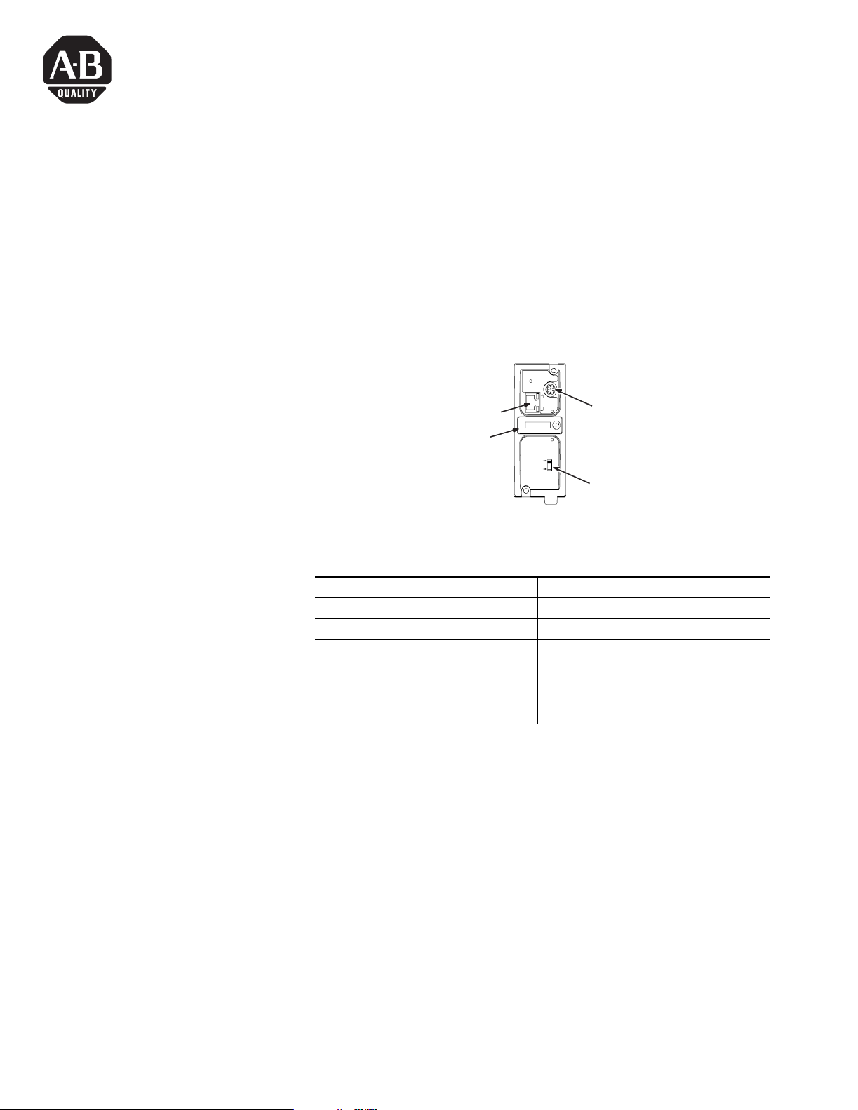
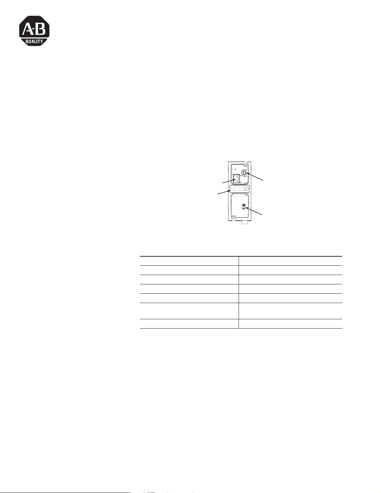
ENI Port Identification
PENI Specifications
ETHERNET
FAULT
RS232
NET
TX/RX
TX/RX
PWR
CABLE
EXTERNAL
IP
Use this write-on area to mark
the Ethernet IP address
RS-232 Mini-DIN (ENI Port 2)
Ethernet Port (ENI Port 1)
Power Source Switch -
(Set to EXTERNAL)
Description ENI Specification
24V dc Power Source Requirement 20.4 to 26.4V dc
24V dc Current Draw 50 mA typical, 100 mA maximum
Maximum Inrush Current 200 mA
Internal Isolation 500V ac for one minute
Operating Ambient Temperature 0°C to +50°C (+32°F to +122°F)
Storage Temperature -40°C to +85°C (-40°F to +185°F)
Publication 2706-IN010C-MU-P
4 InView EtherNet/DeviceNet Module
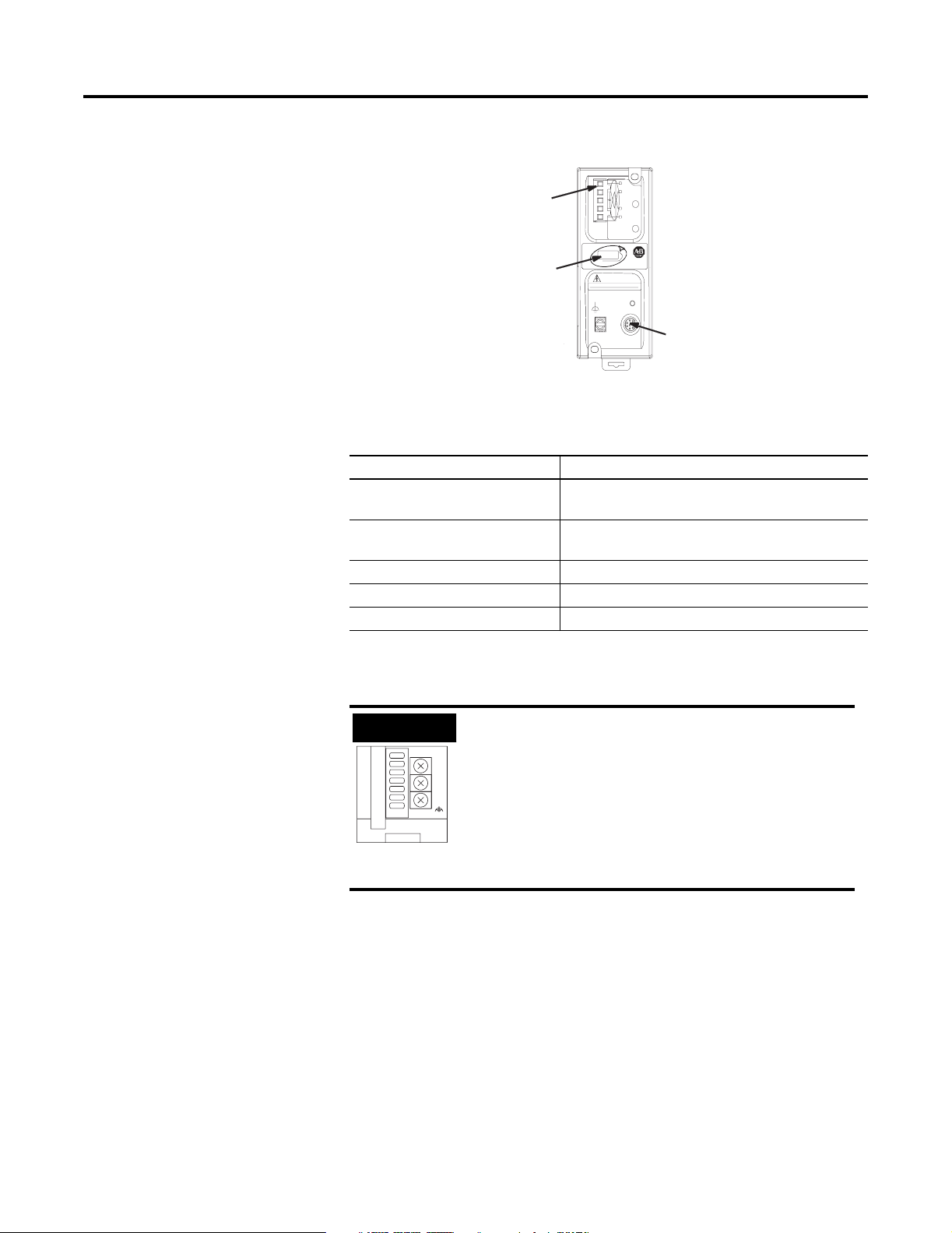
DNI Port Identification
PDNI Specifications
External Power Supply
Wiring
NODE
DANGER
GND
TX/RX
V±
CAN_L
SHIELD
CAN_H
V+
NET
MOD
DeviceNet Port (Port
1) (Replacement
connector part no.
1761-RPL-RT00)
Use this write-on
area to mark the
DeviceNet node
address.
RS-232 Mini-DIN (DNI Port 2)
Description DNI Specification
24V dc Power Source
Requirement
11 to 25 V dc
Current Draw 200 mA typical
400 mA maximum inrush current
Internal Isolation 500V dc
Operating Ambient Temperature 0 to +50°C (+32°F to +122°F)
Storage Temperature -40 to +85° C (-40°F to +185° F)
IMPORTANT
• The PDNI module is powered by the
DeviceNet network power supply.
• The PENI module requires an external 24V dc
power supply.
• Set power source switch to the EXTERNAL
position.
VDC
24
DC
NEUT
CHS
GND
Botto m View
ENI only
Publication 2706-IN010C-MU-P
InView EtherNet/DeviceNet Module 5
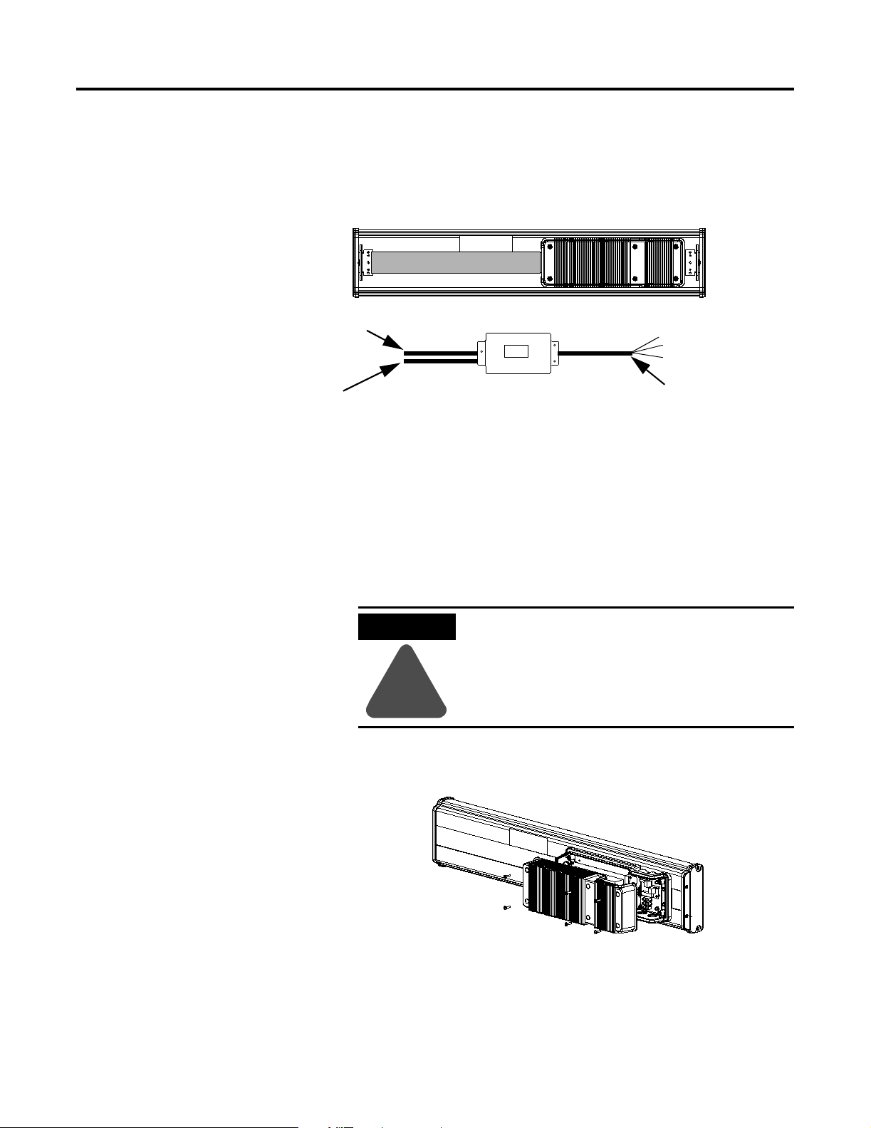
Below is a picture and description of the InView EtherNet/IP and
DeviceNet Interface module and its connectors with relation to an
InView Display.
The PENI module requires a separate 24V dc power supply. The
power supply cable diameter must be between 0.069 in to 0.260 in
(1.75 mm to 6.60 mm). The PENI module Ethernet cable installed must
have a radius of at least 0.5 in (12.7 mm).
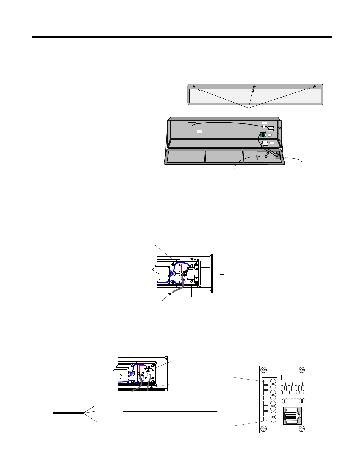
Wiring the EtherNet/IP
Module to InView Display
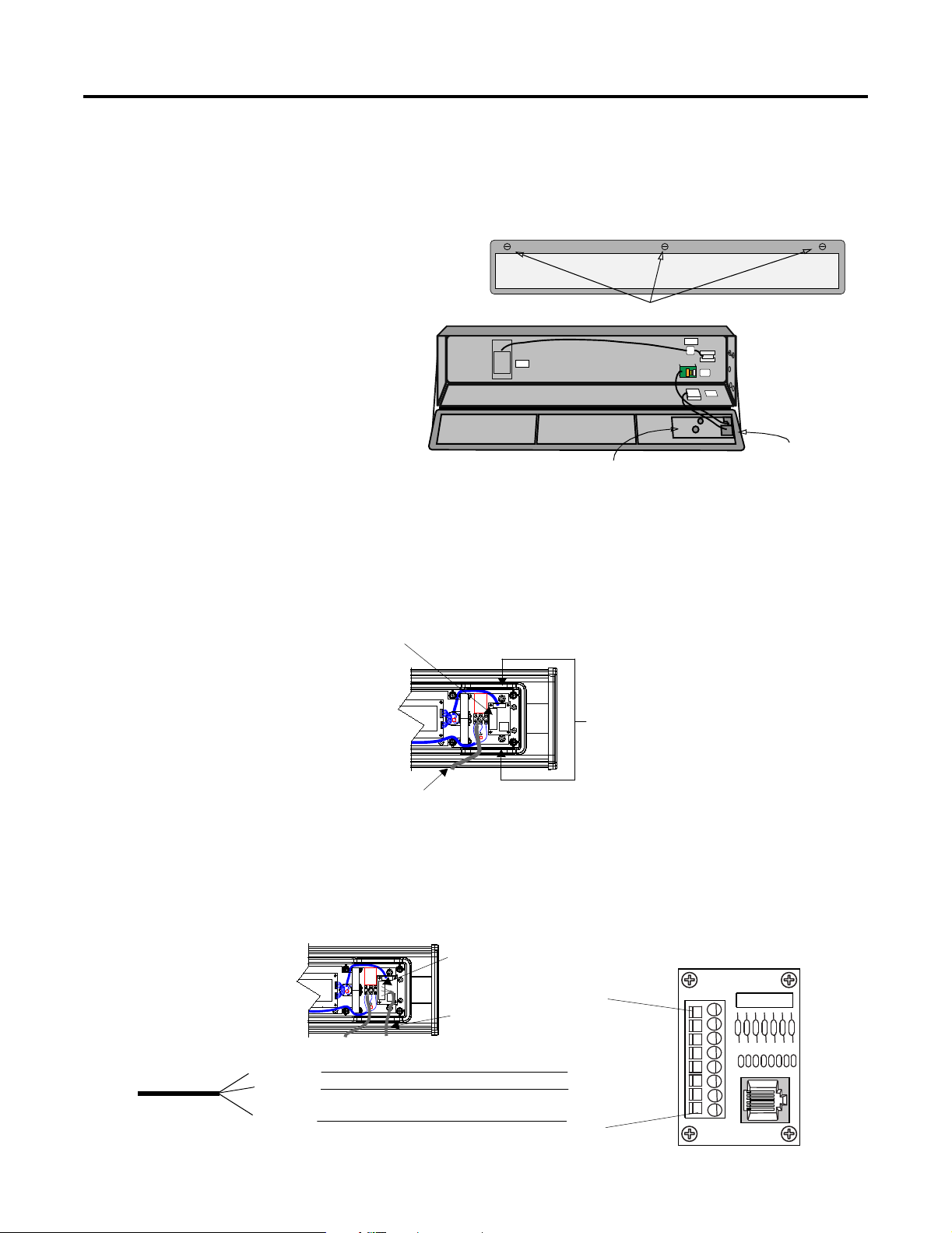
1. Disconnect power to InView display.
2. Remove the power supply cover (on 2706-P4x) by unscrewing
its six screws. Set the screws and cover aside for later step.
NEMA Type 4X Enclosure with Removable Cover
Torque Enclosure Cover screws to 1.1 Nm (10 in-lb).
Customer-supplied
Ethernet/DeviceNet cable
through NEMA-rated
supplied connector
PENI Power Cable
Back of InView Display (P42, P43, P44)
Serial cable to be
connected to terminal
block i nside power supply
cover on back of InView
display
2706-PENI/2706-PDNI
ATTENTION
!
Hazardous voltage. Contact with high voltage
may cause death or serious injury. Always
disconnect power to the InView display prior
to servicing.
2706-P42, 2706-P43, 2706-P44
Publication 2706-IN010C-MU-P
6 InView EtherNet/DeviceNet Module
Open the front of the sign case (on 2706-P7x) by turning the
latches to the left. Carefully let the front of the case drop
forward.
3. Feed the serial cable through the cable grip (shipped with
module).
4. Insert the serial wires through the right conduit opening on
either the top or the bottom of the InView display.
5. Mount the cable grip to the InView display housing. Tighten the
locknut finger-tight and rotate an additional 1/2 turn.
6. Connect the incoming serial wires to the TB1 terminal block.
POWER
LOAD
EARTH
GROUND
Quarter-turn latches
Front view, closed
Front view, open
EPROM unit (on
underside of board)
Controller board
2706-P72,
2706-P74
Power Line
Insert the serial wires
with the cable grip into
one of these conduit
openings.
TB1 Terminal Block for serial connection
Incoming
serial wires
TB1
(NC) 8
(NC) 7
(NC) 6
(NC) 5
(RS-232 RX) 4
(RS-232 TX) 3
(NC) 2
(GND) 1
Brown (Rxd)
Orange (Txd)
Blue (GND)
TB1 Terminal Block
Publication 2706-IN010C-MU-P
InView EtherNet/DeviceNet Module 7
7. Torque the cable grip until the cap is completely seated.
8. Replace the power supply back cover with the 6 screws (on
2706-P4x). Torque the screws to 2.7Nm (24 in-lbs).
Carefully close the sign and tighten the latches (on 2706-P7x).
9. Connect the power supply to a power source.
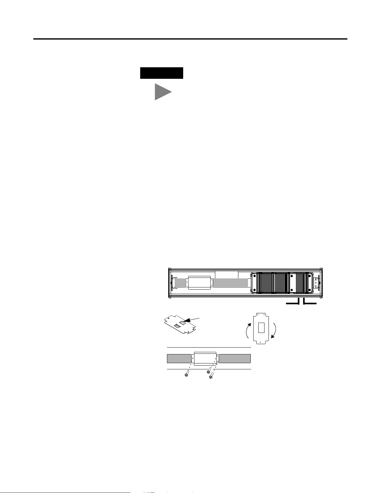
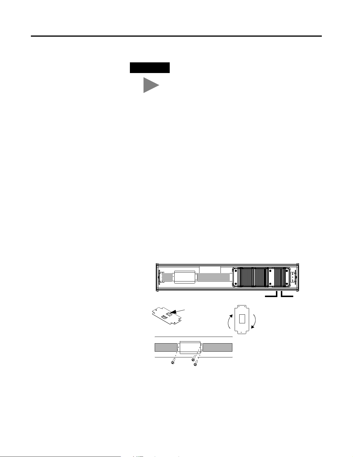
Mounting Module to P42,
P43 and P44 Displays
The InView EtherNet/IP and DeviceNet Interface module is designed
to mount to the track of the InView P42, P43 and P44 displays. The
back plate of the module has tabs for attaching to the track. Tighten
mounting screws until they bottom out against the back plate.
TIP
Be sure to place the wires so they are not caught by
screws when replacing the power supply cover, and
also so they do not interfere with fan operation.
For ease in mounting, rotate
module 90° so that the
mounting holes are on top and
bottom. Rotate the module
clockwise over track until the
alignment is horizontal.
Back Plate
with Tabs
Power Line
Serial Cable
Publication 2706-IN010C-MU-P
8 InView EtherNet/DeviceNet Module
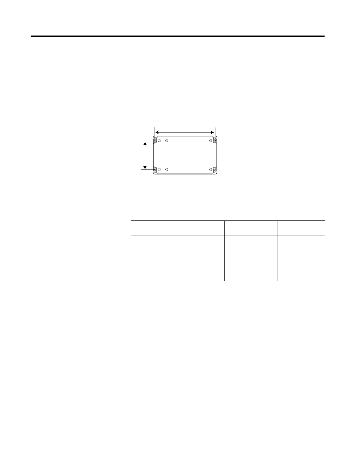
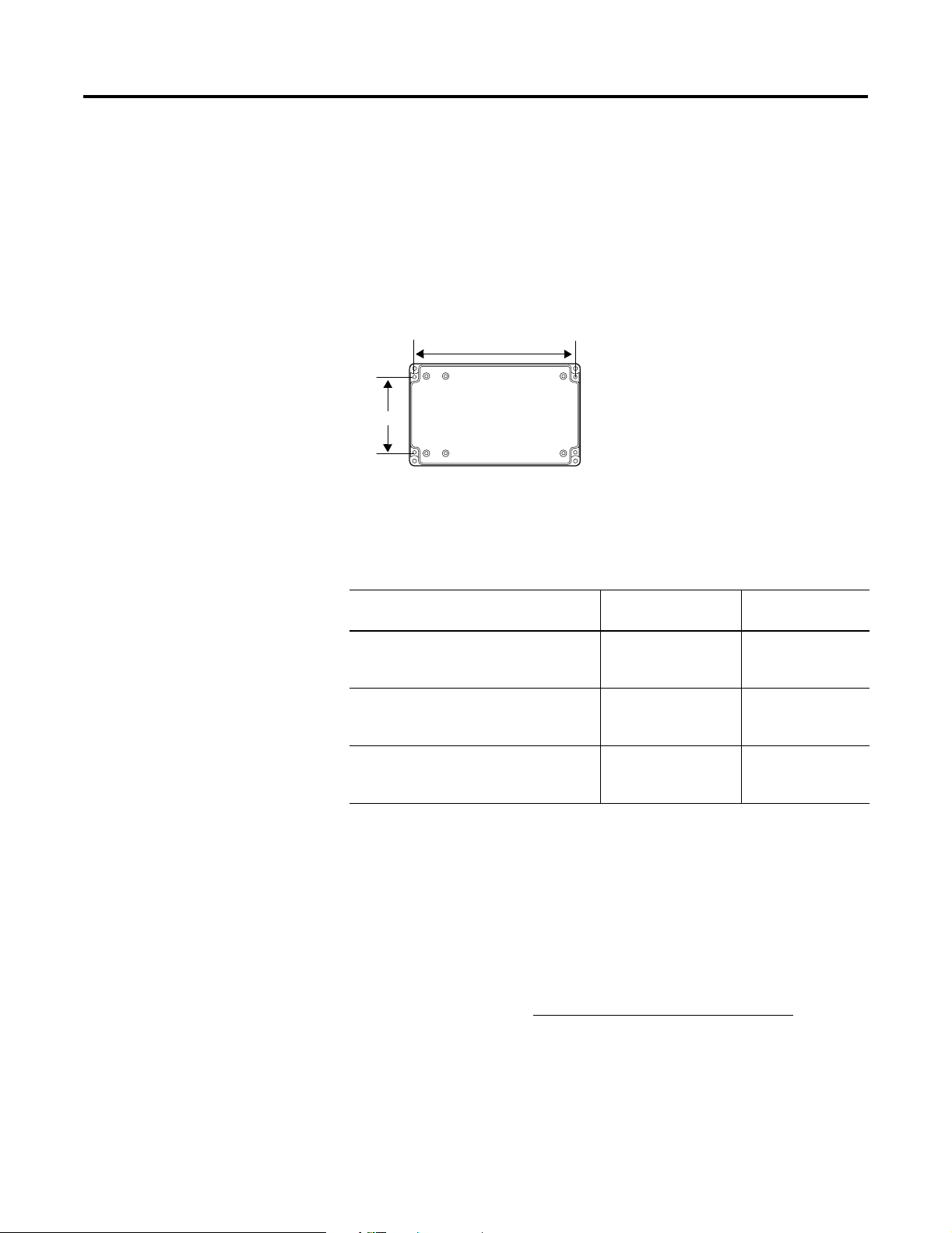
Mounting Module to P72
and P74 Displays
The P72 and P74 InView displays do not have a track for mounting
the module on the display. You can remove the back plate and mount
the bottom of the enclosure to a wall or panel near the display. Use
screws (8-32 UNC-2A) measuring a minimum of 1/4” plus the
thickness of the mounting surface.
The dimensions for the 4 mounting holes are shown below.
For More Information
Related Publications
If you would like a manual, you can:
• download a free electronic version from the internet:
www.ab.com/micrologix or www.theautomationbookstore.com
• purchase a printed manual by:
– contacting your local distributor or Rockwell Automation
representative
– visiting www.theautomationbookstore.com
and placing your
order
– calling (1) 800 963-9548 (USA/Canada)
or (001) 330 725-1574 (Outside USA/Canada)
3.46
(88 mm)
7.40 in (188 mm)
Enclosure Case
For Refer to this
Document
Pub. No.
A more detailed description on how to
install and use your Ethernet Interface.
Ethernet Interface User
Manual
1761-UM006A-EN-P
Instructions on installing a 1761-NET-AIC or
1761-NET-DNI Interface Converter.
AIC+ and DNI
Installation Instructions
1761-5.11
A more detailed description on how to
install and use your DeviceNet Interface.
DeviceNet Interface
User Manual
1761-6.5

Publication 2706-IN010C-MU-P
InView EtherNet/DeviceNet Module 9
Configuration Utilities
A copy of the utilities to configure the ENI and DNI modules is
included on the InView Messaging Software CD (2706-PSW1,
Version 1.1 or later). You can also download the configuration
software from the Internet at:
www.ab.com/plclogic/prodinfo/plcweb/products/mlogix/ABMicroIndex.html

Publication 2706-IN010C-MU-P
10 InView EtherNet/DeviceNet Module
Notes:
11 Public ation 2 706-IN 010C-M U-P
Notice d'installation
Section en français
Module InView Ethernet/IP
(référence 2706-PENI)
Module InView DeviceNet
(référence 2706-PDNI)
Identification du port ENI
Spécifications PENI
ETHERNET
FAULT
RS232
NET
TX/RX
TX/RX
PWR
CABLE
EXTERNAL
IP
Utilisez cette étiquette pour
inscrire l’adresse Ethernet IP
Mini-DIN RS-232 (Port ENI 2)
Port Ethernet (Port ENI 1)
Commutateur de la source
d’alimentation –
(Réglé sur EXTERNAL)
Description Spécification ENI
Puissance de l’alimentation 24 V c.c. 20,4 à 26,4 V c.c.
Consommation électrique 24 V c.c. 50 mA typique, 100 mA maximum
Courant d’appel maximum 200 mA
Isolation interne 500 V c.a. pendant une minute
Température ambiante de
fonctionnement 0 à +50 °C
Température de stockage –40 à +85 °C

Publication 2706-IN010C-MU-P
12 Module InView Ethernet/DeviceNet
Identification du port DNI
Spécifications PDNI
Câblage de l’alimentation
externe
NODE
DANGER
GND
TX/RX
V±
CAN_L
SHIELD
CAN_H
V+
NET
MOD
Port DeviceNet (Port 1)
(Référence du connecteur
de rechange :
1761-RPL-RT00)
Utilisez cette étiquette
pour inscrire l’adresse de
station DeviceNet.
Mini-DIN RS-232 (Port DNI 2)
Description Spécification DNI
Puissance de l’alimentation
24 V c.c.
11 à 25 V c.c.
Consommation électrique 200 mA typique
courant d’appel de 400 mA maximum
Isolation interne 500 V c.c.
Température ambiante de
fonctionnement 0 à +50 °C
Température de stockage –40 à +85 °C
IMPORTANT
• Le module PDNI est alimenté par
l’alimentation du réseau DeviceNet.
• Le module PENI requiert une alimentation
24 V c.c. externe.
• Réglez le commutateur de la source
d’alimentation sur EXTERNAL.
VDC
24
DC
NEUT
CHS
GND
Vue de dessous
ENI uniquement

Public ation 2 706-IN 010C-M U-P
Module InView Ethernet/DeviceNet 13
La figure ci-dessous présente le module d’interface InView Ethernet/IP
et DeviceNet, ainsi que ses connecteurs associés à un afficheur
InView.
Le module PENI requiert une alimentation 24 V c.c. séparée. Le
diamètre du câble d’alimentation doit être compris entre 1,75 mm et
6,6 mm. Le câble Ethernet du module PENI doit avoir un rayon d’au
moins 12,7 mm.
Câblage du module
Ethernet/IP à l’afficheur
InView
1. Déconnectez l’alimentation de l’afficheur InView.
2. Retirez le capot de l’alimentation (2706-P4x) en dévissant les
six vis. Mettez les vis et le capot de côté : vous les réutiliserez
plus tard.
Boîtier NEMA Type 4X avec capot amovible
Le couple de serrage des vis du capot est de 1,1 Nm.
Câble Ethernet/DeviceNet fourni par
l’utilisateur branché sur
le connecteur NEMA fourni
Câble d’alimentation PENI
Arrière de l’afficheur InView (P42, P43, P44)
Câble série à connecter
au bornier situé à
l’intérieur du capot de
l’alimentation, à l’arrière
de l’afficheur InView
2706-PENI/2706-PDNI
ATTENTION
!
Tension dangereuse. Tout contact avec une
tension élevée peut entraîner la mort ou des
blessures graves. Coupez toujours
l’alimentation de l’afficheur InView avant toute
opération de maintenance.
2706-P42, 2706-P43, 2706-P44
Publication 2706-IN010C-MU-P
14 Module InView Ethernet/DeviceNet
Ouvrez la face avant du boîtier (2706-P7x) en tournant les
loquets vers la gauche. Abaissez doucement la face avant du
boîtier vers l’avant.
3. Faites passer le câble série dans le serre-câble (livré avec le
module).
4. Insérez les câbles série dans l’ouverture supérieure ou inférieure
du conduit de l’afficheur InView.
5. Montez le serre-câble sur le boîtier de l’afficheur InView. Serrez
l’écrou à la main, puis effectuez un demi tour supplémentaire.
6. Connectez les fils série entrants au bornier TB1.
POWER
LOAD
EARTH
GROUND
Loquets tournant d’un quart de tour
Vue de face, fermé
Vue de face, ouvert
Unité (EPROM) sur la
face inférieure de la
carte
Carte processeur
2706-P72,
2706-P74
Câble d’alimentation
Insérez les fils série avec
le serre-câble dans
l’une de ces ouvertures du
conduit.
Bornier TB1 pour la connexion série
Fils série entrant
TB1
(NC) 8
(NC) 7
(NC) 6
(NC) 5
(RS-232 RX) 4
(RS-232 TX) 3
(NC) 2
(GND) 1
Marron (Rxd)
Orange (Txd)
Bleu (TERRE)
Bornier TB1
Public ation 2 706-IN 010C-M U-P
Module InView Ethernet/DeviceNet 15
7. Serrez le serre-câble jusqu’à ce que la selle soit bien ajustée.
8. Remettez le capot de l’alimentation en place à l’aide des six vis
(afficheurs 2706-P4x). Serrez les vis avec un couple de 2,7 Nm.
Fermez la face avant du boîtier et serrez les loquets (afficheurs
2706-P7x).
9. Branchez l’alimentation sur une source d’alimentation.
Montage du module sur les
afficheurs P42, P43 et P44
Le module d’interface InView Ethernet/IP et DeviceNet est conçu pour
être monté sur la glissière des afficheurs InView P42, P43 et P44. Les
pattes situées sur la plaque de montage du module permettent de le
fixer sur la glissière. Serrez les vis de fixation jusqu’à ce qu’elles soient
contre la plaque de montage.
CONSEIL
Veillez à positionner les câbles de façon à ce qu’ils
ne soient pas coincés par les vis lorsque vous
remettrez le capot de l’alimentation en place et qu’ils
n’empêchent pas le bon fonctionnement du
ventilateur.
Pour faciliter le montage,
pivotez le module de 90° afin
que les trous de fixation se
trouvent en haut et en bas.
Faites pivoter le module sur la
glissière dans le sens des
aiguilles d’une montre, jusqu’à
ce qu’il soit aligné
horizontalement.
Plaque de montage
avec pattes
Ligne secteur
Câble série
Publication 2706-IN010C-MU-P
16 Module InView Ethernet/DeviceNet
Montage du module sur les
afficheurs P72 et P74
Les afficheurs InView P72 et P74 ne comportent pas de glissière pour
le montage du module. Vous pouvez retirer la plaque de montage et
monter la partie inférieure du boîtier sur un mur ou un panneau situé
près de l’afficheur. Utilisez des vis (8-32 UNC-2A) d’une longueur
minimale de 6 mm plus l’épaisseur de la surface de montage.
Les espacements des 4 trous de fixation sont indiqués ci-dessous.
Pour plus d’informations
Publications connexes
Pour obtenir un manuel, vous pouvez :
• charger gratuitement un exemplaire électronique sur l’un des
sites Internet suivants :
www.ab.com/micrologix ou www.theautomationbookstore.com
• acheter un exemplaire imprimé. Pour cela :
– contactez votre distributeur ou votre représentant Rockwell
Automation ;
– visitez notre site www.theautomationbookstore.com
et passez
votre commande ;
– appelez le 800 963-9548 (Etats-Unis/Canada)
ou le +1 330 725-1574 (hors Etats-Unis/Canada).
88 mm
188 mm
Boîtier
Pour Reportez-vous à ce
document
Référence
Une description plus détaillée sur
l’installation et l’utilisation de votre
interface Ethernet
Interface Ethernet pour
MicroLogix (ENI) –
Manuel utilisateur
1761-UM006A-FR-P
Des instructions sur l’installation d’un
convertisseur d’interface 1761-NET-AIC ou
1761-NET-DNI
AIC+ and DNI
Installation Instructions
1761-5.11
Une description plus détaillée sur
l’installation et l’utilisation de votre
interface DeviceNet
DeviceNet Interface
User Manual
1761-6.5
Loading...