


 Loading...
ModularDeviceNet
Starter Auxiliary
I/O
Bulletin 198 Series C
User Manual

Important User Information
Because of the variety of uses for the products described in this publication, those responsible for the application and use of this control equipment must satisfy themselves that all necessary steps have been taken to assure that each application and use meets all performance and safety requirements, including any applicable laws, regulations, codes and standards.
The illustrations, charts, sample programs and layout examples shown in this guide are intended solely for purposes of example. Since there are many variables and requirements associated with any particular installation, Allen-Bradley does not assume responsibility or liability (to include intellectual property liability) for actual use based upon the examples shown in this publication.
Allen-Bradley publication SGI-1.1, Safety Guidelines for the Application, Installation and Maintenance of Solid-State Control (available from your local Allen-Bradley office), describes some important differences between solid-state equipment and electromechanical devices that should be taken into consideration when applying products such as those described in this publication.
Reproduction of the contents of this copyrighted publication, in whole or part, without written permission of Rockwell Automation, is prohibited.
Throughout this manual we use notes to make you aware of safety considerations:
|
Identifies information about practices or circumstances that can lead |
|
ATTENTION |
||
to personal injury or death, property damage or economic loss |
||
|
!
Attention statements help you to:
•identify a hazard
•avoid a hazard
•recognize the consequences
|
Identifies information that is critical for successful application and |
|
IMPORTANT |
||
understanding of the product. |
||
|
||
|
Allen-Bradley, RSNetWorx, PLC, SLC, Distributed Starters, and Modular DSA are registered trademarks of Rockwell Automation
DeviceNet is a trademark of the Open DeviceNet Vendor Association (ODVA).
European Union Directive Compliance
If this product has the CE mark it is approved for installation within the European Union and EEA regions. It has been designed and tested to meet the following directives.
EMC Directive
This product is tested to meet Council Directive 89/336/EEC Electromagnetic Compatibility (EMC) using the following standards, in whole or in part, documented in a technical construction file:
•EN 50081-2 EMC — Generic Emission Standard, Part 2 — Industrial Environment
•EN 50082-2 EMC — Generic Immunity Standard, Part 2 — Industrial Environment
This product is intended for use in an industrial environment.
Low Voltage Directive
This product is also designated to meet Council Directive 73/23/EEC Low Voltage, by applying the safety requirements of EN 60947-5-1 — Low Voltage Switchgear and Control Gear — Control Circuit Devices and Switching Elements — Electromechanical Control Circuit Devices.
This equipment is classified as open equipment and must be mounted in an enclosure during operation to provide safety protection.

Preface
Manual Objectives
The purpose of this manual is to provide you with the necessary information to apply the Bulletin 198 Modular DeviceNet Starter Auxiliary (Modular DSA I/O System). Described
in this manual are methods for installing, configuring, and troubleshooting the Bulletin 198 System of components.
IMPORTANT |
Read this manual in its entirety before installing, operating, servicing, |
|
or configuring the Bulletin 198 Modular DSA I/O System. |
||
|
Intended Audience
This manual is intended for qualified personnel responsible for the setup and service of these devices. You must have previous experience with and a basic understanding of communications terminology, configuration procedures, required equipment, and safety precautions.
You should understand the DeviceNet network operations, including how slave devices operate on the network and communicate with a DeviceNet master.
You should be familiar with the use of the RSNetWorx for DeviceNet Software (Cat. No. 9357-DNET L3) for network configuration. This software package is referred to often in this manual.
|
Read the DeviceNet |
Cable System Planning and Installation |
|
IMPORTANT |
|||
Manual, Pub. No. 1485-6.7.1, in its entirety before planning and |
|||
|
|||
|
|||
|
installing a DeviceNet |
System. If the network is not installed |
|
according to this document, unexpected operation and intermittent failures can occur.
If this manual is not available, please contact either the local Allen-Bradley Distributor or sales Office to request a copy. Copies may also be ordered from the Rockwell Automation Bookstore. The Bookstore can be contacted via the Internet from the Allen-Bradley home page at http://www.ab.com.
Publication 198-UM002A-EN-P December 2001

Preface vi
ATTENTION
!
Only personnel familiar with DeviceNet devices and associated equipment should plan or implement the installation, start-up, configuration, and subsequent maintenance of the Modular DSA I/O System. Failure to comply may result in personal injury and/or equipment damage.
Vocabulary
Note the following references throughout this manual:
•Bulletin 198 with its options is referred to as the Modular DSA I/O System or MDSA.
•DeviceNet is referred to as Dnet or DNET.
•The Programmable Logic Controller is referred to as the Programmable controller, PLC controller, or SLC controller.
•Earth Ground is referred to as GND.
•The National Electrical Code is referred to as NEC.
Reference Manuals
Product |
Reference Manuals |
|
|
For RSNetWorx for DeviceNet Software |
Pub. No. 1787-6.5.3 |
|
(RSNetWorx Software Manual,) |
|
|
For SLC 500 and 1747-SDN |
Pub. No. 1747-5.8 |
|
(DeviceNet Scanner Module Installation Instructions) |
|
|
For PLC-5 and 1771-SDN |
Pub. No. 1771-5.14 |
|
(DeviceNet Scanner Module Installation Instructions) |
|
|
For DeviceNet Cables and Components |
Pub. No. DN-2.5 |
|
(DeviceNet Overview) |
|
|
Publication 198-UM002A-EN-P December 2001

vii Preface
Publication 198-UM002A-EN-P December 2001

Table of Contents
Preface
Manual Objectives . . . . . . . . . . . . . . . . . . . . . . . . . . . . . . . . . . . . . . . . . . . . . . . . . . . . . . . . . . . v Intended Audience . . . . . . . . . . . . . . . . . . . . . . . . . . . . . . . . . . . . . . . . . . . . . . . . . . . . . . . . . . . v Vocabulary . . . . . . . . . . . . . . . . . . . . . . . . . . . . . . . . . . . . . . . . . . . . . . . . . . . . . . . . . . . . . . . . . vi Reference Manuals . . . . . . . . . . . . . . . . . . . . . . . . . . . . . . . . . . . . . . . . . . . . . . . . . . . . . . . . . . . vi
Chapter 1 — Product Overview
Chapter Objectives . . . . . . . . . . . . . . . . . . . . . . . . . . . . . . . . . . . . . . . . . . . . . . . . . . . . . . . . . . 1-1
System Description. . . . . . . . . . . . . . . . . . . . . . . . . . . . . . . . . . . . . . . . . . . . . . . . . . . . . . . . . . 1-1
Cat. Nos. . . . . . . . . . . . . . . . . . . . . . . . . . . . . . . . . . . . . . . . . . . . . . . . . . . . . . . . . . . . . . . . . . . 1-4
DeviceNet Compatibility . . . . . . . . . . . . . . . . . . . . . . . . . . . . . . . . . . . . . . . . . . . . . . . . . . . . . 1-4
Chapter 2 — Installation
Chapter Objectives . . . . . . . . . . . . . . . . . . . . . . . . . . . . . . . . . . . . . . . . . . . . . . . . . . . . . . . . . . 2-1
Storage and Operation . . . . . . . . . . . . . . . . . . . . . . . . . . . . . . . . . . . . . . . . . . . . . . . . . . . . . . . 2-1
Electrostatic Discharge . . . . . . . . . . . . . . . . . . . . . . . . . . . . . . . . . . . . . . . . . . . . . . . . . . . . . . 2-2
Remove Power . . . . . . . . . . . . . . . . . . . . . . . . . . . . . . . . . . . . . . . . . . . . . . . . . . . . . . . . . . . . . 2-2
Approximate Dimensions . . . . . . . . . . . . . . . . . . . . . . . . . . . . . . . . . . . . . . . . . . . . . . . . . . . . 2-3
Module Installation. . . . . . . . . . . . . . . . . . . . . . . . . . . . . . . . . . . . . . . . . . . . . . . . . . . . . . . . . . 2-4
DIN Rail Mounting . . . . . . . . . . . . . . . . . . . . . . . . . . . . . . . . . . . . . . . . . . . . . . . . . . . . . . . . . 2-4
Gland Plate Mounting . . . . . . . . . . . . . . . . . . . . . . . . . . . . . . . . . . . . . . . . . . . . . . . . . . . . . . . 2-5
Wiring Diagrams. . . . . . . . . . . . . . . . . . . . . . . . . . . . . . . . . . . . . . . . . . . . . . . . . . . . . . . . . . . . 2-7
Chapter 3 — Operation
Chapter Objectives . . . . . . . . . . . . . . . . . . . . . . . . . . . . . . . . . . . . . . . . . . . . . . . . . . . . . . . . . . 3-1 Basic Configuration (Accepting I/O Module Configuration) . . . . . . . . . . . . . . . . . . . . . . . . 3-1 DeviceNet MAC ID (Node Address) Configuration . . . . . . . . . . . . . . . . . . . . . . . . . . . . . . . 3-4 Autobaud Configuration . . . . . . . . . . . . . . . . . . . . . . . . . . . . . . . . . . . . . . . . . . . . . . . . . . . . . 3-7 Choosing the I/O Assembly Data Format . . . . . . . . . . . . . . . . . . . . . . . . . . . . . . . . . . . . . . . 3-8 Mapping to the Scanner . . . . . . . . . . . . . . . . . . . . . . . . . . . . . . . . . . . . . . . . . . . . . . . . . . . . . 3-10 Advanced Topics . . . . . . . . . . . . . . . . . . . . . . . . . . . . . . . . . . . . . . . . . . . . . . . . . . . . . . . . . . 3-12
Registering Unrecognized Devices in RSNetWorx . . . . . . . . . . . . . . . . . . . . . . . . . . . 3-12 COS Mask Parameters. . . . . . . . . . . . . . . . . . . . . . . . . . . . . . . . . . . . . . . . . . . . . . . . . . 3-18 Input Filtering . . . . . . . . . . . . . . . . . . . . . . . . . . . . . . . . . . . . . . . . . . . . . . . . . . . . . . . . 3-20 DeviceNet Explicit Messaging . . . . . . . . . . . . . . . . . . . . . . . . . . . . . . . . . . . . . . . . . . . 3-20 I/O Modules and DeviceNet . . . . . . . . . . . . . . . . . . . . . . . . . . . . . . . . . . . . . . . . . . . . 3-21 Mod/Net Status LED . . . . . . . . . . . . . . . . . . . . . . . . . . . . . . . . . . . . . . . . . . . . . . . . . . 3-26 I/O Status LED. . . . . . . . . . . . . . . . . . . . . . . . . . . . . . . . . . . . . . . . . . . . . . . . . . . . . . . 3-26

ix Table of Contents
Chapter 4 — Programming
Chapter Objectives . . . . . . . . . . . . . . . . . . . . . . . . . . . . . . . . . . . . . . . . . . . . . . . . . . . . . . . . . 4-1
I/O Mapping . . . . . . . . . . . . . . . . . . . . . . . . . . . . . . . . . . . . . . . . . . . . . . . . . . . . . . . . . . . . . . 4-1
Verifying the Input Assembly. . . . . . . . . . . . . . . . . . . . . . . . . . . . . . . . . . . . . . . . . . . . . 4-4
Verifying the Output Assembly . . . . . . . . . . . . . . . . . . . . . . . . . . . . . . . . . . . . . . . . . . . 4-6
Programming Explicit Messages . . . . . . . . . . . . . . . . . . . . . . . . . . . . . . . . . . . . . . . . . . 4-8
Chapter 5 — Specifications
198-DNG, 198-DN (DeviceNet Modules) . . . . . . . . . . . . . . . . . . . . . . . . . . . . . . . . . . . . . . 5-1 Mod/Net Status LED . . . . . . . . . . . . . . . . . . . . . . . . . . . . . . . . . . . . . . . . . . . . . . . . . . . . . . . 5-1 I/O Status LED . . . . . . . . . . . . . . . . . . . . . . . . . . . . . . . . . . . . . . . . . . . . . . . . . . . . . . . . . . . 5-3 198-DNP (Mini DIN Pass-Through) . . . . . . . . . . . . . . . . . . . . . . . . . . . . . . . . . . . . . . . . . . . 5-6 198-IB2S (Sensor Module) . . . . . . . . . . . . . . . . . . . . . . . . . . . . . . . . . . . . . . . . . . . . . . . . . . . 5-8 198-IB4 (4-Input DC Module) . . . . . . . . . . . . . . . . . . . . . . . . . . . . . . . . . . . . . . . . . . . . . . . 5-11 198-IB4S Series A (4-Input DC Module DS). . . . . . . . . . . . . . . . . . . . . . . . . . . . . . . . . . . . 5-14 198-IA2 (2-Input AC Module) . . . . . . . . . . . . . . . . . . . . . . . . . . . . . . . . . . . . . . . . . . . . . . . 5-17 198-IA2-G4 Series A (AC Sensor Module) . . . . . . . . . . . . . . . . . . . . . . . . . . . . . . . . . . . . . 5-20 198-IA1-G4 9000 Series A (9000 Sensor Module) . . . . . . . . . . . . . . . . . . . . . . . . . . . . . . . 5-23 198-OW2S (2-Relay Output Gland) . . . . . . . . . . . . . . . . . . . . . . . . . . . . . . . . . . . . . . . . . . . 5-26 198-OW2 Series A (2-Relay Output DIN Module) . . . . . . . . . . . . . . . . . . . . . . . . . . . . . . . 5-28 198-OW2-G4 Series A (Relay Valve Module) . . . . . . . . . . . . . . . . . . . . . . . . . . . . . . . . . . . 5-31 198-OW2S-Q5 Series A (DeviceNet Valve Module). . . . . . . . . . . . . . . . . . . . . . . . . . . . . . 5-34 198-IA2XOW1 Series A and B (AC Starter Module) . . . . . . . . . . . . . . . . . . . . . . . . . . . . . 5-36 198-IB2XOB1 Series A and B (DC Starter Module) . . . . . . . . . . . . . . . . . . . . . . . . . . . . . . 5-42 198-IB2XOW1 Series A and B (DC Input Relay Output Module) . . . . . . . . . . . . . . . . . . 5-49 198-IB2XOB5S Series A (Drive Preset Speed Module) . . . . . . . . . . . . . . . . . . . . . . . . . . . 5-56 198-IB2XOB2S-Q5 Series A (Drive Preset Speed Module) . . . . . . . . . . . . . . . . . . . . . . . . 5-62 198-G1P (Gland Plates) . . . . . . . . . . . . . . . . . . . . . . . . . . . . . . . . . . . . . . . . . . . . . . . . . . . . 5-67
Chapter 6 — Troubleshooting
Chapter Objectives . . . . . . . . . . . . . . . . . . . . . . . . . . . . . . . . . . . . . . . . . . . . . . . . . . . . . . . . . 6-1
Diagnostics. . . . . . . . . . . . . . . . . . . . . . . . . . . . . . . . . . . . . . . . . . . . . . . . . . . . . . . . . . . . . . . . 6-1
Red I/O Light . . . . . . . . . . . . . . . . . . . . . . . . . . . . . . . . . . . . . . . . . . . . . . . . . . . . . . . . . . . . . 6-1
Red I/O Light — Noise . . . . . . . . . . . . . . . . . . . . . . . . . . . . . . . . . . . . . . . . . . . . . . . . . . . . . 6-2
DeviceNet Connection and Autobaud. . . . . . . . . . . . . . . . . . . . . . . . . . . . . . . . . . . . . . . . . . 6-2
Low DeviceNet Voltage . . . . . . . . . . . . . . . . . . . . . . . . . . . . . . . . . . . . . . . . . . . . . . . . . . . . . 6-2
Excessive Number of Modules. . . . . . . . . . . . . . . . . . . . . . . . . . . . . . . . . . . . . . . . . . . . . . . . 6-3
Invalid ID. . . . . . . . . . . . . . . . . . . . . . . . . . . . . . . . . . . . . . . . . . . . . . . . . . . . . . . . . . . . . . . . . 6-3
Checksum Error . . . . . . . . . . . . . . . . . . . . . . . . . . . . . . . . . . . . . . . . . . . . . . . . . . . . . . . . . . . 6-3
Discontinuity Error . . . . . . . . . . . . . . . . . . . . . . . . . . . . . . . . . . . . . . . . . . . . . . . . . . . . . . . . . 6-3
I/O Module Current Errors . . . . . . . . . . . . . . . . . . . . . . . . . . . . . . . . . . . . . . . . . . . . . . . . . . 6-4
Publication 198-UM002A-EN-P December 2001

Table of Contents |
x |
|
|
Sensor Undervoltage Error . . . . . . . . . . . . . . . . . . . . . . . . . . . . . . . . . . . . . . . . . . . . . . . . . . . 6-4
Shorted and Open Sensor Detection. . . . . . . . . . . . . . . . . . . . . . . . . . . . . . . . . . . . . . . . . . . . 6-4
Appendix A — DeviceNet Information
Product Identification . . . . . . . . . . . . . . . . . . . . . . . . . . . . . . . . . . . . . . . . . . . . . . . . . . . . . . A-1
Product Type . . . . . . . . . . . . . . . . . . . . . . . . . . . . . . . . . . . . . . . . . . . . . . . . . . . . . . . . . A-1
Product Code . . . . . . . . . . . . . . . . . . . . . . . . . . . . . . . . . . . . . . . . . . . . . . . . . . . . . . . . . A-1
DeviceNet Implementation . . . . . . . . . . . . . . . . . . . . . . . . . . . . . . . . . . . . . . . . . . . . . . . . . . A-1
Operating Modes . . . . . . . . . . . . . . . . . . . . . . . . . . . . . . . . . . . . . . . . . . . . . . . . . . . . . . . . . . A-2
Power-up Reset Mode . . . . . . . . . . . . . . . . . . . . . . . . . . . . . . . . . . . . . . . . . . . . . . . . . . A-2
Run Mode. . . . . . . . . . . . . . . . . . . . . . . . . . . . . . . . . . . . . . . . . . . . . . . . . . . . . . . . . . . . A-3
Error Mode . . . . . . . . . . . . . . . . . . . . . . . . . . . . . . . . . . . . . . . . . . . . . . . . . . . . . . . . . . A-3
I/O Error Mode . . . . . . . . . . . . . . . . . . . . . . . . . . . . . . . . . . . . . . . . . . . . . . . . . . . . . . A-3
I/O Idle Mode . . . . . . . . . . . . . . . . . . . . . . . . . . . . . . . . . . . . . . . . . . . . . . . . . . . . . . . . A-3
DeviceNet Object Definitions. . . . . . . . . . . . . . . . . . . . . . . . . . . . . . . . . . . . . . . . . . . . . . . . A-4
Identity Object . . . . . . . . . . . . . . . . . . . . . . . . . . . . . . . . . . . . . . . . . . . . . . . . . . . . . . . . A-4
Message Router . . . . . . . . . . . . . . . . . . . . . . . . . . . . . . . . . . . . . . . . . . . . . . . . . . . . . . . A-6
DeviceNet Object . . . . . . . . . . . . . . . . . . . . . . . . . . . . . . . . . . . . . . . . . . . . . . . . . . . . . A-6
Assembly Object. . . . . . . . . . . . . . . . . . . . . . . . . . . . . . . . . . . . . . . . . . . . . . . . . . . . . . . . . . . A-7
I/O Modules and “Byte-wise” I/O Assemblies . . . . . . . . . . . . . . . . . . . . . . . . . . . . . A-7
Byte-wise Output (Consumed) Assembies . . . . . . . . . . . . . . . . . . . . . . . . . . . . . . . . . A-10
Byte-wise Input (Produced) Assemblies . . . . . . . . . . . . . . . . . . . . . . . . . . . . . . . . . . . A-14
I/O Modules and “Nibble-wise” I/O Assemblies. . . . . . . . . . . . . . . . . . . . . . . . . . . A-16
Nibble-wise Output (Consumed) Assembies . . . . . . . . . . . . . . . . . . . . . . . . . . . . . . . A-18
Nibble-wise Input (Produced) Assembies . . . . . . . . . . . . . . . . . . . . . . . . . . . . . . . . . A-19
Custom Parameter Based “Word-wise” I/O Assemblies . . . . . . . . . . . . . . . . . . . . . A-19
“Word-wise” Bit-Packed Assemblies . . . . . . . . . . . . . . . . . . . . . . . . . . . . . . . . . . . . . A-20
Assembly Object Services . . . . . . . . . . . . . . . . . . . . . . . . . . . . . . . . . . . . . . . . . . . . . . A-23
I/O Assembly Instance Summary. . . . . . . . . . . . . . . . . . . . . . . . . . . . . . . . . . . . . . . . A-24
Connection Object . . . . . . . . . . . . . . . . . . . . . . . . . . . . . . . . . . . . . . . . . . . . . . . . . . . . . . . . A-25
Discrete Input Point Object . . . . . . . . . . . . . . . . . . . . . . . . . . . . . . . . . . . . . . . . . . . . . . . . A-28
Discrete Output Point Object . . . . . . . . . . . . . . . . . . . . . . . . . . . . . . . . . . . . . . . . . . . . . . . A-29
Discrete Input Group Object . . . . . . . . . . . . . . . . . . . . . . . . . . . . . . . . . . . . . . . . . . . . . . . A-30
Discrete Output Group Object . . . . . . . . . . . . . . . . . . . . . . . . . . . . . . . . . . . . . . . . . . . . . . A-30
Acknowledge Handler Object . . . . . . . . . . . . . . . . . . . . . . . . . . . . . . . . . . . . . . . . . . . . . . . A-31
DeviceNet Interface Object. . . . . . . . . . . . . . . . . . . . . . . . . . . . . . . . . . . . . . . . . . . . . . . . . A-31
Publication 198-UM002A-EN-P December 2001

xi Table of Contents
Appendix B — Motor Starter Operation
Setting the Motor Starter Type . . . . . . . . . . . . . . . . . . . . . . . . . . . . . . . . . . . . . . . . . . . . . . . . B-2
Motor Starter I/O Assemblies . . . . . . . . . . . . . . . . . . . . . . . . . . . . . . . . . . . . . . . . . . . . . . . . B-3
Standard Distributed Starter I/O Assemblies . . . . . . . . . . . . . . . . . . . . . . . . . . . . . . . . B-3
Inverter Type Distributed Starter I/O Assemblies . . . . . . . . . . . . . . . . . . . . . . . . . . . . B-5
Distributed Starter Specific DeviceNet Objects . . . . . . . . . . . . . . . . . . . . . . . . . . . . . . . . . . B-5
Control Supervisor Object . . . . . . . . . . . . . . . . . . . . . . . . . . . . . . . . . . . . . . . . . . . . . . . B-6
Overload Object . . . . . . . . . . . . . . . . . . . . . . . . . . . . . . . . . . . . . . . . . . . . . . . . . . . . . . . B-6
Publication 198-UM002A-EN-P December 2001
Chapter 1
Product Overview
Chapter Objectives
This chapter contains the following information:
•System description
•DeviceNet compatibility
•European Union Directive compliance
System Description
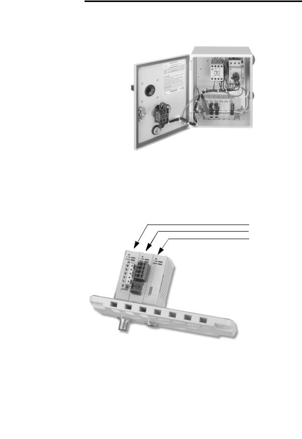
The Bulletin 198 Modular DSA I/O System is a cost-effective, glandular I/O system designed specifically for Distributed Starters (Figure 1.2) and general starter panels. The Modular DSA I/O System consists of a DeviceNet module followed by up to 16 I/O modules. The modules can be arranged in any combination and appear as one node on a DeviceNet network. Since the Modular DSA I/O System was designed specifically for Distributed Starters, it not only provides the ability to control and monitor devices such as motor starters, sensors, solenoids and load feeders, but also provides for cable connections to those devices, eliminating the expense and problems of traditional wiring.
Publication 198-UM002A-EN-P December 2001
1-2 Product Overview
Figure 1.1 Typical Distributed Starter — Modular DSA I/O System Modules Mounted on a Gland Plate in an Enclosed Combination Motor Starter
The Modular DSA I/O System can be mounted traditionally on a DIN Rail or on a Gland Plate to accrue benefits of wire simplification.
The Modular DSA I/O System mounted to a gland plate allows for easy connection from outside the enclosure for DeviceNet, standard sensors, and other auxiliary devices via M12 micro quick-disconnect connectors.
Figure 1.2 Modular DSA I/O System Mounted on a Gland Plate
198-DNG
198-IB2XOW1 or similar
198-IB2S
Publication 198-UM002A-EN-P December 2001
Product Overview |
1-3 |
|
|
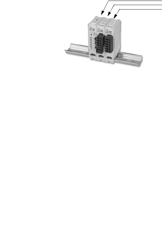
Figure 1.3 Modular DSA I/O System Mounted on DIN Rail
198-DN
198-IB2XOW1 or similar
198-IB4
The Modular DSA I/O System provides specially designed modules that provide many benefits in a distributed architecture. The Sensor Module (198-IB2S) is specifically designed to interface standard photoelectric and proximity sensors from the area surrounding the enclosure. Since the connection for standard sensors is available outside the enclosure via an M12 connector, and power is sourced from DeviceNet, no additional wiring is necessary.
The Starter Modules (198-IA2XOW1, 198-IB2XOB1, and 198-IB2XOW1) are designed to provide a fast, effective way to control and gather the basic information from either a DC operated or an AC operated starter.
The connections to specific 190D/191D Compact Combination Starters are made via cable harnesses, such as Cat. No. 198-MSACBL6. Additionally, the 198-IB2XOW1 module sources input power from DeviceNet. This allows many applications to turn off control power and still be able to read the inputs for diagnostics.
Publication 198-UM002A-EN-P December 2001

1-4 Product Overview
Cat. Nos.
The catalog numbering scheme for the Modular DSA I/O System is explained in Figure 1.4 and Figure 1.5 below. Note that all cat. nos. begin with 198, which stands for Bulletin 198 Modular DSA I/O System.
Figure 1.4 Modular DSA — DeviceNet Cat. No.
198 – DNG
|
|
|
|
|
|
|
|
|
|
|
|
|
|
|
|
|
|
|
|
|
|
Bulletin No. |
|
|
|
|
|
|
|
G |
Gland Plate |
|
|
|
|
|
|
|
|
|
|
No Selection |
DIN Mount |
|
|
|
|
|
|
|
|
|
|
|
|
|
|
|
|
|
|
|
|
|
|
|
|
|
DN |
DeviceNet |
|
|
|
|||
|
|
|
|
|
|
|
|
|
|
|
Figure 1.5 Modular DSA I/O System — I/O Module Cat. No.
198 – IB2XOB2S-Q5
|
|
|
|
|
|
|
|
|
|
|
|
|
|
|
|
|
|
|
|
|
|
|
|
|
|
|
|
|
|
|
|
|
|
|
|
|
|
|
|
|
|
|
|
|
|
|
|
|
|
|
|
|
|
|
|
|
|
|
|
|
|
|
|
|
|
|
|
|
|
Bulletin No. |
|
|
|
|
|
|
|
|
|
|
|
|
|
|
|
|
|
|
|
|
|
|
|
|
|
Q5 |
M12 1-Key 5-Pin |
|||||||
|
|
|
|
|
|
|
|
|
|
|
|
|
|
|
|
|
|
|
|
|
|
|
|
|
|
|
|
G4 |
1/2" 2-Key 4-Pin |
|||||
|
|
|
|
|
|
|
|
|
|
|
|
|
|
|
|
|
|
|
|
|
|
|
|
|
|
|
|
|
|
|
|
|
|
|
|
|
|
|
|
|
|
|
|
|
|
|
|
|
|
|
|
|
|
|
|
|
|
|
|
|
|
|
|
|
|
|
|
|
|
|
|
|
Input |
|
|
|
|
|
|
|
|
|
|
|
|
|
|
|
|
|
|
|
|
|
|
|
|
|
|
|
|
|
|
|
|
|
|
|
|
|
|
|
|
|
|
|
|
|
|
|
|
|
|
|
|
|
|
|
|
|
|
|
|
|
|
|
|
|
|
|
|
|
|
|
|
|
|
|
|
|
|
|
|
|
|
|
|
|
|
|
|
|
|
|
|
|
|
DeviceNet Sourced |
|
|||||
|
|
|
|
|
|
|
|
|
|
|
|
|
|
|
|
|
|
|
|
|
|
|
|
|
|
|
|
|
||||||
|
|
|
|
|
|
|
|
|
|
|
|
|
|
|
|
|
|
|
|
|
|
|
|
|
|
|
|
|
|
|
|
|
||
|
|
|
|
|
|
|
|
|
|
|
|
|
|
|
|
|
|
|
|
|
|
|
|
|
|
|
|
|
|
|
|
|
|
|
|
|
|
Input Type |
|
|
|
|
|
|
|
|
|
|
|
|
|
|
|
|
|
|
|
|
|
|
|
|
|
|
|||||
|
|
|
A |
|
AC |
|
|
|
|
|
|
|
|
|
|
|
|
|
|
|
|
|
|
|
|
|
|
|
|
|
||||
|
|
|
B |
|
DC |
|
|
|
|
|
|
|
|
|
|
|
|
|
|
|
|
|
|
No. of Outputs |
|
|
||||||||
|
|
|
|
|
|
|
|
|
|
|
|
|
|
|
|
|
|
|
|
|
|
|
|
|
|
|
|
|
||||||
|
|
|
|
|
|
|
|
|
|
|
|
|
|
|
|
|
|
|
|
|
|
|
||||||||||||
|
|
|
|
|
|
|
|
|
|
|
|
|
|
|
|
|
|
|
|
|
|
|
|
|
|
|
|
|
|
|
|
|
|
|
|
|
|
|
|
|
|
|
|
|
|
|
|
|
|
|
|
|
|
|
|
|
|
|
|
|
|
|
|
|
|
|
|
|
|
|
|
|
|
|
|
|
|
|
|
|
|
|
|
|
|
|
|
|
|
|
|
|
|
|
|
|
|
|
|
|
|
|
|
|
|
|
|
|
|
No. of Inputs |
|
|
|
|
|
|
|
|
|
|
|
|
|
Output Type |
|
|
|
|
|
||||||||||
|
|
|
|
|
|
|
|
|
|
|
|
|
|
|
|
|
|
|
|
|
|
|
|
|
|
|
|
|
|
|
|
|
|
|
|
|
|
|
|
|
|
|
|
|
|
|
|
|
|
|
|
|
|
|
|
|
|
|
|
W |
|
|
Relay |
|
|
|
|
|
|
|
|
|
|
|
|
|
|
|
|
|
|
|
|
|
|
|
|
|
|
|
|
|
|
|
|
|
|
|
|
|
|
|
|
|
|
|
|
|
|
|
|
|
|
|
|
|
|
|
|
|
|
|
|
|
|
|
|
|
|
B |
|
|
DC |
|
|
|
|
|
|
|
|
|
|
|
|
|
|
|
|
|
|
AND |
|
|
|
|
|
|
|
|
|
|
|
|
|
|
|
|
|
|
|
|
||
|
|
|
|
|
|
|
|
|
|
|
|
|
|
|
|
|
|
|
|
|
|
|
|
|
|
|
|
|
|
|
|
|
|
|
|
|
|
|
|
|
|
|
|
|
|
|
|
|
|
|
|
|
|
Output |
|
|
|
|
|
|
|
|
|
|
|
|
|
||
|
|
|
|
|
|
|
|
|
|
|
|
|
|
|
|
|
|
|
|
|
|
|
|
|
|
|
|
|
|
|
|
|
|
|
DeviceNet Compatibility
The Modular DSA I/O System communicates as a Group 2 slave device via DeviceNet Protocol. It supports the Explicit, Polled I/O, Cyclic I/O, and Change of State (COS) I/O messaging of the predefined master/slave connection set and two additional explicit connections available through Group 1 or Group 3.
Publication 198-UM002A-EN-P December 2001

Chapter 2
Installation
Chapter Objectives
This chapter contains information about:
•Device storage and operating environment
•Mounting
•Connecting and wiring
Storage and Operation
To prolong the product life, take the following precautions:
•Store within an ambient temperature range of –40…+85°C (–40…+185°F).
•Store within a relative humidity range of 0…95%, non-condensing.
•Avoid storing or operating the device where it could be exposed to a corrosive atmosphere.
•Protect from moisture and direct sunlight.
•Operate at an ambient temperature range of –25…+60°C (–4…+140°F). The Modular DSA I/O System enclosure is suitable for an ambient of –25…+40°C.
Modular DSA I/O System is suitable for use in an industrial environment when installed in accordance with these instructions. Specifically, this equipment is intended for use in a clean, dry environment (Pollution Degree 2 ) .
Pollution Degree 2 is an environmentally where, normally, only non-conductive pollution occurs except occasionally a temporary conductivity caused by condensation shall be expected.
Pollution Degree 2 is an International Electrotechnical Commission (IEC) designations.
Publication 198-UM002A-EN-P December 2001

2-2 Installation
Electrostatic Discharge
|
Electrostatic discharge can damage integrated circuits or |
|
IMPORTANT |
||
semiconductors if you touch bus connector pins. Follow these |
||
|
||
|
||
|
guidelines when you handle the module. |
• Touch a grounded object to discharge static potential.
• Do not touch the bus connector or connector pins.
• Do not touch circuit components inside the module.
Remove Power
|
Remove power before removing or inserting a module in the I/O |
|
IMPORTANT |
||
line-up. When you remove or insert a module with power applied, an |
||
|
||
|
||
|
electrical arc may occur. An electrical arc can cause personal injury or |
|
|
property damage by: |
|
|
• Sending an erroneous signal to your system’s field devices |
|
|
• Causing damage to the product |
Electrical arcing causes excessive wear on module contacts Worn contacts may create electrical resistance.
Publication 198-UM002A-EN-P December 2001

Installation 2-3
Approximate Dimensions
Dimensions are in millimeters (inches).
Figure 2.1 DIN Module Mounting Dimensions
78 |
77 |
76 |
|
(3-1/16) |
(2-31/32) |
||
(3-1/16) |
|||
|
|
||
98 |
85 |
78 |
|
(3-27/32) |
(3-3/32) |
||
(3-11/32) |
|||
|
|
18
(11/16)
|
Maintain spacing from enclosure walls, wireways, adjacent equipment, |
|
IMPORTANT |
||
etc. Allow 25 mm (1 in.) of space on all sides for adequate ventilation, |
||
|
||
|
||
|
as shown: |
|
|
Vent Side |
End
End
25mm (1 in)
|
|
|
25mm (1 in) |
|
|
Vent |
|
|
|
|
|
|
|||||||
|
|
|
|
|
|
|
|
|
|
|
Side |
|
|
|
|
|
|
||
|
|
|
|
|
|
|
|
|
|
|
|
|
|
|
|
|
|||
|
|
|
|
|
|
|
|
|
|
|
|
|
|
|
|
|
|
|
|
DeviceNet |
|
|
DSA-ModI/O |
|
|
DSA-ModI/O |
DSA-ModI/O |
|
DSA-ModI/O |
(1 in) |
|
||||||||
|
|
|
|
|
|
|
|
|
|
|
|
|
|
|
|
|
End |
|
|
|
|
|
|
|
|
|
|
|
|
|
|
|
|
|
|
|
|||
|
|
|
|
|
|
|
|
|
|
|
|
|
|
|
|
25mm |
|
||
|
|
|
|
|
|
|
|
|
|
|
|
|
|
|
|
|
|
|
|
|
|
|
|
|
|
|
|
|
|
|
|
|
|
|
|
|
|
|
|
|
|
|
|
|
|
|
|
|
|
|
|
|
|
|
|
|
|
|
|
|
|
|
|
|
|
|
|
|
|
|
|
Connector |
|
|
|
|
|
||
|
25mm (1 in) |
|
|
|
|
|
|
|
|
|
|||||||||
|
|
|
|
|
Side |
|
|
|
|
|
|||||||||
|
|
|
|
|
|
|
|
|
|
|
|
|
|
|
|
|
|||
|
|
|
|
|
|
Connector Side |
|
|
|
|
|
||||||||
|
|
|
|
|
|
|
|
|
|
|
|
|
|
||||||
|
|
|
|
|
|
|
|
|
|
|
|
|
|
||||||
End
Publication 198-UM002A-EN-P December 2001

2-4 Installation
Module Installation
The I/O System can be mounted either on a DIN Rail or a Gland Plate.
|
|
During gland plate or DIN Rail mounting of all devices, be sure that |
|
IMPORTANT |
|
|
debris (metal chips, wire strands, etc.) do not fall into the module. Such |
|
|
|
|
|
|
|
|
|
debris could cause damage on power-up. |
|
|
|
|
|
|
|
|
When attaching I/O modules, it is very important that the modules |
|
IMPORTANT |
|
|
are fully seated on either the DIN Rail or the gland plate. This ensures |
|
|
|
|
|
|
|
|
|
that the module-to-module connectors are properly mated and that |
|
|
the modules are properly grounded. |
|
|
|
DIN Rail Mounting
The Modular DSA I/O System modules can be mounted using either the 35 x 7.5 mm (EN 50 022-35 x 7.5) or 35 x 15 mm (EN 50 022-35 x 15) DIN Rail.
Figure 2.2 DIN Rail Mounting and Removal
198-DN |
|
|
|
1 |
|
|
2 |
|
1 |
2 |
|
Click |
3 |
|
Click |
||
|
Publication 198-UM002A-EN-P December 2001
Installation 2-5
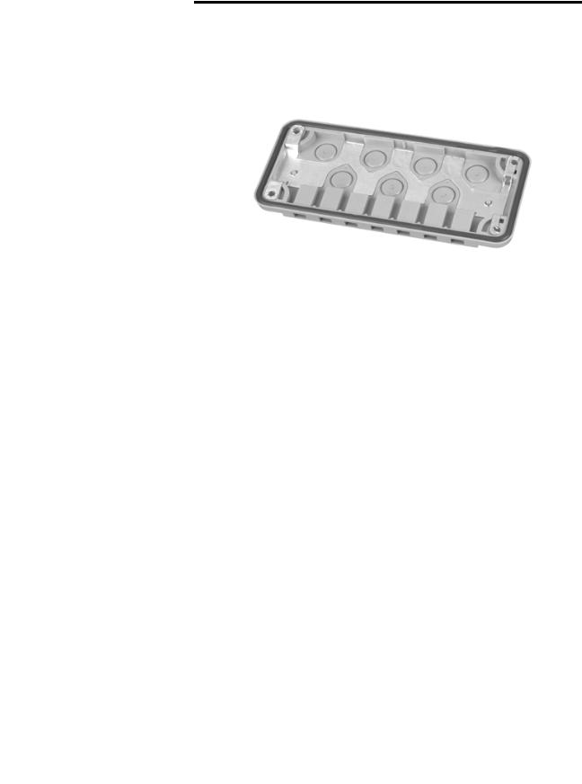
Gland Plate Mounting
Gland plates may also be referred to as cable plates. These plates are designed to cover rectangular holes in standard enclosures, and to allow easy power and signal access to the enclosure.
Figure 2.3 Plastic Gland Plate
Refer to Chapter 5 for a complete list of gland plate specifications.
Publication 198-UM002A-EN-P December 2001
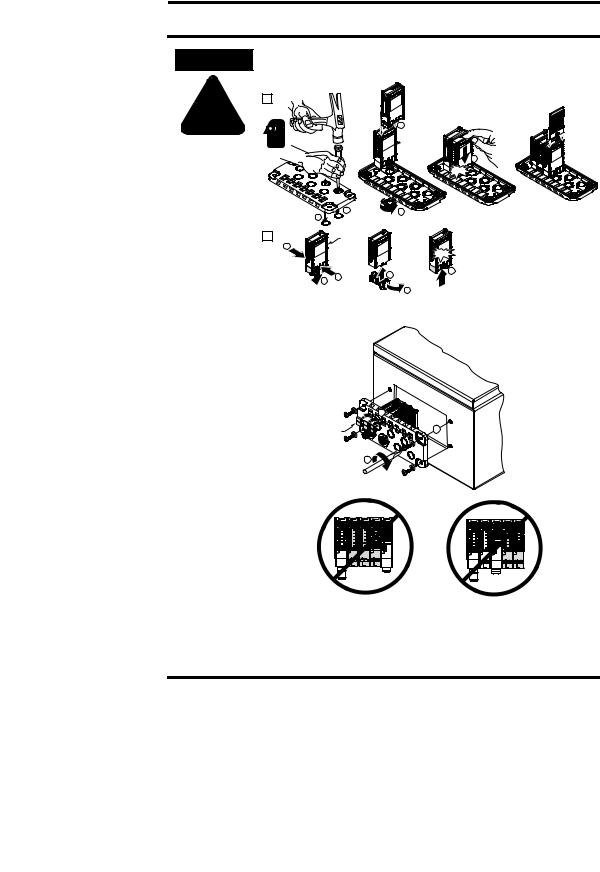
2-6 Installation
ATTENTION
!
The gland plate must be on a flat secure surface and safety glasses must be worn when opening the knockouts.
1
4
 198-DNG
5
Click
2 |
|
1 |
1.12 - 1.35 N-m |
3 |
|
|
(10 - 12 lb-in) |
|
|
2 |
|
198-IB2S |
|
|
1 |
|
198-OW2S |
|
|
|
198-DNG |
|
|
|
|
|
|
|
Click |
|
|
|
|
5 |
|
2 |
1 |
|
4 |
|
|
|
|
|
3
Installation of Gland Plate and Modular DSA I/O System in Enclosure
|
3 |
1492-SM8X9 |
1 |
2
2.25 - 2.8 N-m
(20 - 25 lb-in)
•No more than two DIN Modules between Gland Modules
•No more than one DIN Module to the right of the Gland Module
•Consult Allen-Bradley for information on exceeding these specifications
Publication 198-UM002A-EN-P December 2001
Installation 2-7
Figure 2.4 Physical Diagram of Connecting Control Power to I/O Modules
198-IA2XOW1
1  198-IB2XOB1
198-IB2XOW1
198-OW2S
.324 - 2.08 mm2
22 - 14 AWG
2
Wiring Diagrams
Refer to appropriate module in Chapter 5 for wiring information.
Publication 198-UM002A-EN-P December 2001

Chapter 3
Operation
Chapter Objectives
This chapter contains the following information:
•Configuring the Modular DSA I/O System
•DeviceNet Explicit Messaging
•Mod/Net Status LED
•I/O Status LED
Basic Configuration (Accepting I/O Module Configuration)
This section will provide the user with the basic steps for configuring an MDSA on DeviceNet. It also contains specific examples of how to configure a device using RSNetWorx for DeviceNet.
The first step to setting up a system that contains an MDSA is to power up the MDSA DeviceNet module. Once it is powered up, it will attempt to determine the network baud, and set its baud rate appropriately. While the MDSA DeviceNet module is determining the network baud rate, the Mod/Net Status LED will blink green for ¼ second, red for ¼ second, then turn off. This pattern will be repeated until the baud rate is determined.
|
If there is no traffic on the network, the device will not be able to |
|
IMPORTANT |
||
determine the network baud rate. The Mod/Net Status LED will to |
||
|
||
|
||
|
continue to repeat the green/red/off blinking pattern until network |
|
|
traffic is detected |
Once the proper baud rate is set, the Mod/Net Status LED will either blink green or turn solid green. If the Mod/Net Status LED turns solid red, it has most likely failed its “Duplicate MAC ID Check”, which means that the MDSA DeviceNet module has detected another device on the network with the same node address or “MAC ID”. Note that automatic baud rate detection can be disabled to allow a baud rate to be manually configured (see Advanced Topics on page 3-12)
The first time that an MDSA DeviceNet module is powered up, the I/O Status LED will turn solid red. This indicates that the configuration of the I/O modules has not been accepted.
Publication 198-UM002A-EN-P December 2001
Operation 3-2
Accepting the configuration of the I/O modules is a part of the device configuration process outlined below.
To begin the configuration of DeviceNet, execute the RSNetworx software and complete the following procedure.
1.From the menu, choose . After “online” has been selected you will see the following screen:
2.Choose the appropriate DeviceNet/PC interface and click OK. RSNetWorx will tell the user to upload or download devices before viewing configuration.
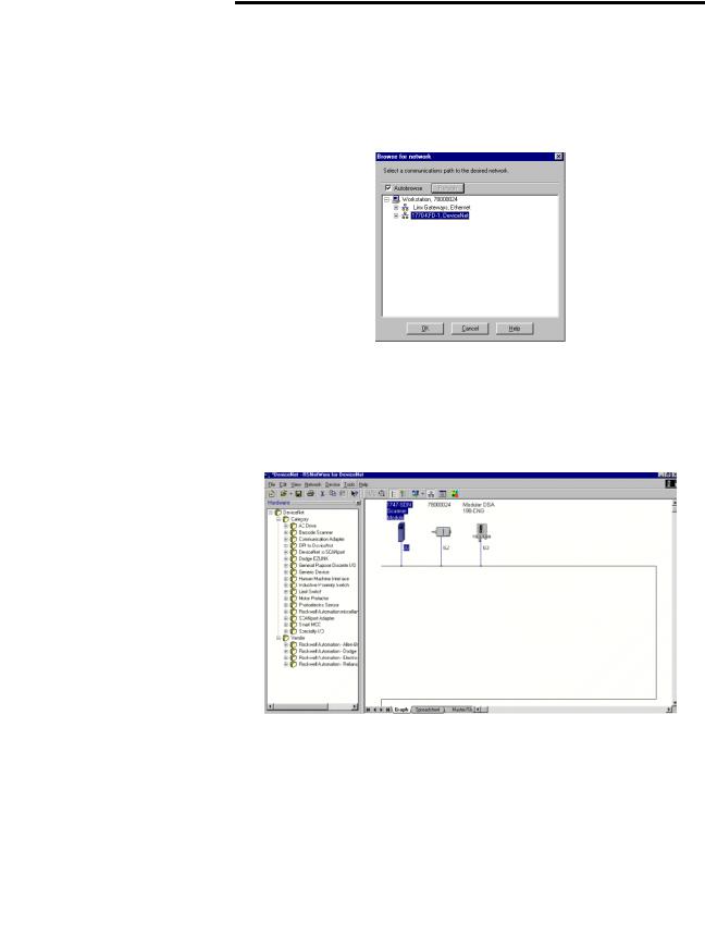
3.Select the button. RSNetWorx will now browse the network and display all of the nodes it has detected on the network.
RSNetWorx will display an icon and the name and node address of each device on the network. The figure below shows the RSNetWorx window after browsing the network.
If the name of the device shows up as “Unrecognized Device” it means that the device is not registered. (see Advanced Topics on page 3-12).
Publication 198-UM002A-EN-P December 2001
3-3 Operation
The user is now able to configure the MDSA. The following steps outline how to accept the configuration of the I/O modules. This will result in the I/O Status LED changing from solid red to off.
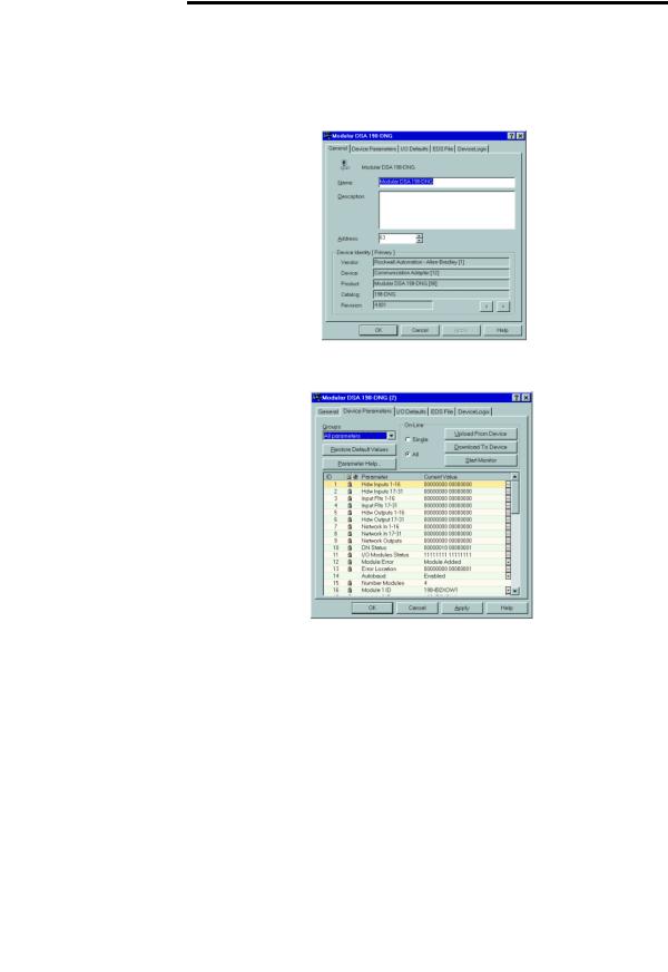
1.Double click on the MDSA icon. RSNetWorx will verify the identity of the device, and then display the following screen:
2.Select the “Parameter” tab. RSNetWorx will prompt the user to upload the parameters from the device. Select the button. The following screen appears:
3.From the screen shown, verify that the number of I/O modules and the names of the modules recognized are correct. Select the Accept Config parameter (parameter 48 or 58). Double click the value of that parameter. A drop-down list of options will appear. Select the Accept Config option.
4.Select the button. RSNetWorx will ask you whether it should download the changes to the device. Select . The device will reset, and the I/O Status LED will turn off. The MOD/NET status LED will be flashing green, waiting to establish connections to other nodes.
Publication 198-UM002A-EN-P December 2001
Operation 3-4
DeviceNet MAC ID (Node Address) Configuration
The DeviceNet node address may be set to a value from 0…63. Note that in most DeviceNet systems, node address 0 is usually reserved for the master device. Node address 63 is generally the factory default for slave devices. Node addresses can be changed in three different ways. The first two ways outlined below are accomplished via DeviceNet using the software setting, while the third is done by setting the hardware switches that reside on the MDSA DeviceNet module.
|
|
The MDSA must be offline before performing the following procedures. |
|
IMPORTANT |
|
|
|
|
|
|
|
|
|
|
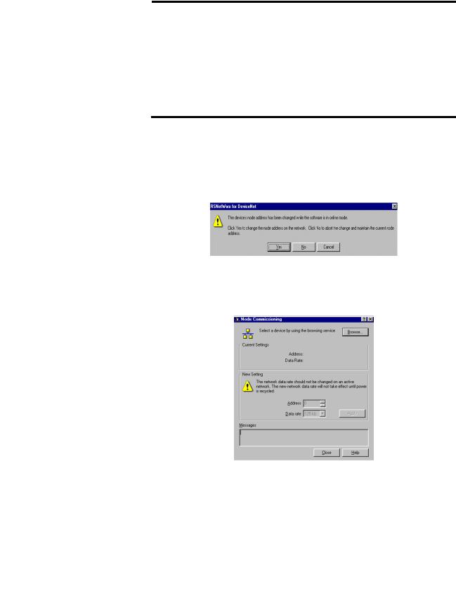
1.The first manner of changing the node address is accomplished by double clicking on the existing node number. The user will then be able to erase the existing node number and enter the desired node number. Once the desired node number has been entered, deselect the device and the following screen will appear:
2.From the above screen, select the button and the node number will be changed. The second way of changing a node address can be done by following the steps shown below.
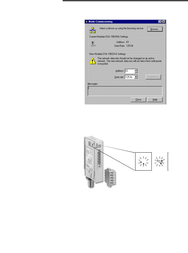
1.From the menu, choose The following screen will appear:
Publication 198-UM002A-EN-P December 2001
3-5 Operation
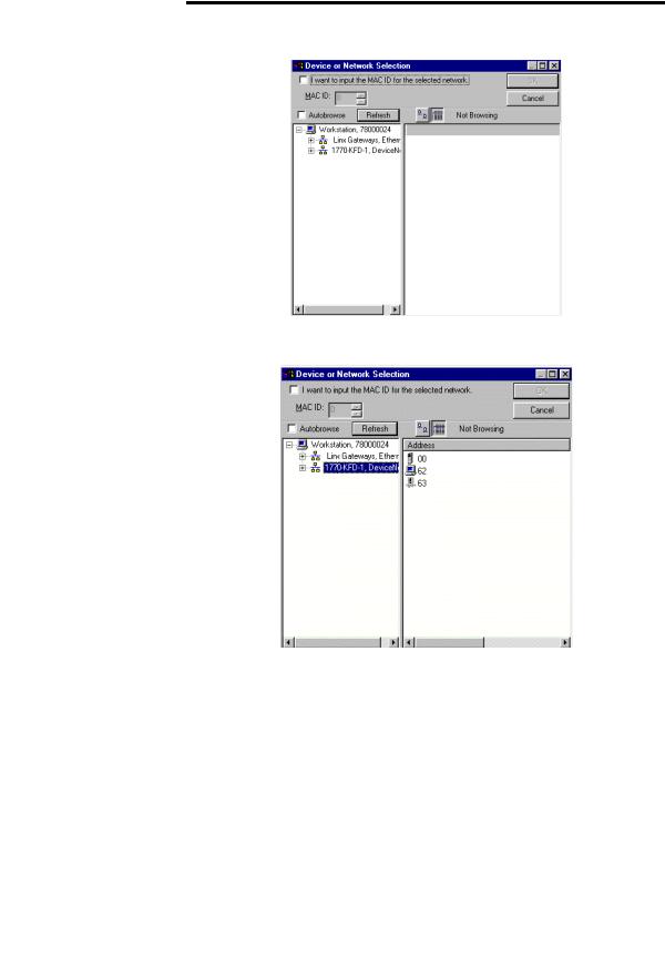
2. Click the button to upload the network. The following screen will appear:
3.From this screen select the appropriate PC interface. For our example we will use the 1770-KFD-1. After the appropriate interface is chosen the following screen appears:
Publication 198-UM002A-EN-P December 2001
Operation 3-6
4.Select the MDSA device and press the button. After RSNetworx has finished updating the network the following screen will appear:
5.Choose the desired node address and click the Apply button.
6.Click the Exit button. The unit will reset and power up at the new node address.
7.Re-browse the network. The MDSA should appear at the new node address.
The final way to set the node address is by directly setting the node address switches found on the MDSA DeviceNet module.
Node Address
0 0
8  2 8
2 8  2
2
6 4 6 4
MSB LSB
Address 63 Shown
Publication 198-UM002A-EN-P December 2001
3-7 Operation
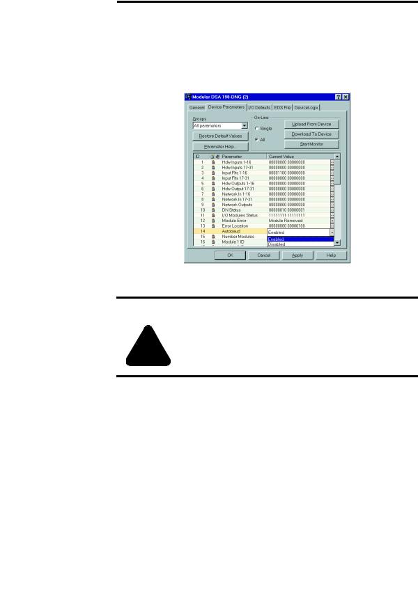
Autobaud Configuration
Automatic baud rate detection can be enabled/disabled by setting the value of the Autobaud parameter (parameter 14).
1.To change the setting of the Autobaud parameter, click the pull down tab for that parameter in the parameter window as shown below:
2.After choosing the desired setting, click the button. You will then be asked to download the configuration to the device. Click .
|
Injury or damage may occur when parameters are not set according to |
|
ATTENTION |
||
the application requirements |
||
|
!
When the Autobaud parameter has the value Enable, the MDSA DeviceNet module will attempt to match the network baud rate at power up. When the parameter has the value Disabled, the powerup auto-baud feature is disabled. When the Autobaud parameter is changed, the new value will be applied when the power is cycled after saving the value to the device.
Publication 198-UM002A-EN-P December 2001
Operation 3-8
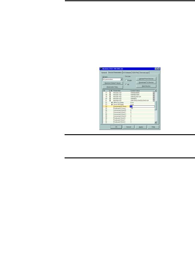
Choosing the I/O Assembly Data Format
Consumed Assemblies (sometimes referred to as Output Assemblies) define the format of I/O message data that is consumed by the MDSA. The MDSA generally consumes I/O messages to command the state of its outputs.
Choosing the size and format of the I/O data that is consumed by an MDSA is done by choosing a Consumed Assembly instance number. This instance number is written to the Consumed IO Assy parameter (parameter 34 in the Cat. No. 198-DN; parameter 24 in the Cat. No. 198-DNG). Refer to Appendix on page A-1 to determine which Consumed Assembly instance to select. The different instances/formats allow flexibility for different systems. The screen below shows the Consumed IO Assy parameter in the parameter list of a Cat. No. 198-DNG module.
|
The Consumed IO Assy parameter value can not be changed while the |
|
IMPORTANT |
||
MDSA is online with a scanner. Any attempts to change the value of this |
||
|
||
|
||
|
parameter while online with a scanner will result in the error message |
|
|
“Object State Conflict”. |
After the Consumed IO Assembly has been chosen and downloaded to the MDSA, select
and . This will update the I/O Consumed Size parameter value (parameter 48 or 38). Record this value to be used later in the Scanner I/O mapping.
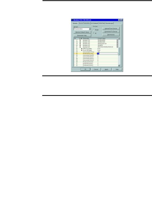
Produced Assemblies (sometimes referred to as Input Assemblies) define the format of the I/O message data that is produced by the MDSA. The MDSA generally produces I/O messages that contain the fault status of the MDSA, and the state of the MDSA’s inputs.
Choosing the size and format of the I/O data that is produced by an MDSA is done by choosing a Produced Assembly instance number. This instance number is written to the Produced IO Assy parameter (parameter 35 in the Cat. No. 198-DN; parameter 25 in the Cat. No. 198-DNG). Refer to Appendix on page A-1 to determine which Produced Assembly instance to select. The different instances/formats allow flexibility for different systems. The
Publication 198-UM002A-EN-P December 2001
3-9 Operation
screen below shows the Produced IO Assy parameter in the parameter list of a Cat. No. 198-DNG module.
|
The Produced IO Assy parameter value can not be changed while the |
|
IMPORTANT |
||
MDSA is online with a scanner. Any attempts to change the value of this |
||
|
||
|
||
|
parameter while online with a scanner will result in the error message |
|
|
“Object State Conflict”. |
After the Produced IO Assembly has been chosen and downloaded to the MDSA, select
and . This will update the I/O Produced Size parameter value (parameter 49 or 39). Record this value to be used later in the Scanner I/O mapping.
Publication 198-UM002A-EN-P December 2001
Loading...