


 Loading...
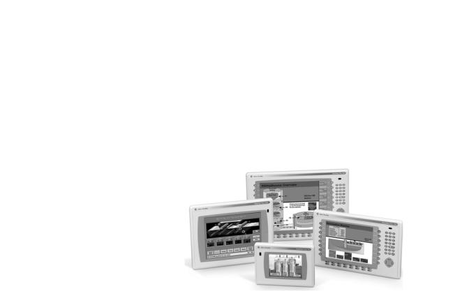
PanelView Plus Terminals
Catalog Number 2711P
400, 600, 700, 1000, 1250, 1500 Terminals
User Manual
Important User Information
Solid state equipment has operational characteristics differing from those of electromechanical equipment. Safety Guidelines for the Application, Installation and Maintenance of Solid State Controls (publication SGI-1.1 available from your local Rockwell Automation sales office or online at http://www.rockwellautomation.com/literature/) describes some important differences between solid state equipment and hard-wired electromechanical devices. Because of this difference, and also because of the wide variety of uses for solid state equipment, all persons responsible for applying this equipment must satisfy themselves that each intended application of this equipment is acceptable.
In no event will Rockwell Automation, Inc. be responsible or liable for indirect or consequential damages resulting from the use or application of this equipment.
The examples and diagrams in this manual are included solely for illustrative purposes. Because of the many variables and requirements associated with any particular installation, Rockwell Automation, Inc. cannot assume responsibility or liability for actual use based on the examples and diagrams.
No patent liability is assumed by Rockwell Automation, Inc. with respect to use of information, circuits, equipment, or software described in this manual.
Reproduction of the contents of this manual, in whole or in part, without written permission of Rockwell Automation, Inc., is prohibited.
Throughout this manual, when necessary, we use notes to make you aware of safety considerations.
WARNING
Identifies information about practices or circumstances that can cause an explosion in a hazardous environment, which may lead to personal injury or death, property damage, or economic loss.
IMPORTANT Identifies information that is critical for successful application and understanding of the product.
ATTENTION
Identifies information about practices or circumstances that can lead to personal injury or death, property damage, or economic loss. Attentions help you identify a hazard, avoid a hazard, and recognize the consequence
SHOCK HAZARD
Labels may be on or inside the equipment, for example, a drive or motor, to alert people that dangerous voltage may be present.
BURN HAZARD
Labels may be on or inside the equipment, for example, a drive or motor, to alert people that surfaces may reach dangerous temperatures.
Allen-Bradley, PanelView Plus, FactoryTalk View, FactoryTalk View ME, FactoryTalk ViewPoint, FactoryTalk View Studio, RSLinx Enterprise, Rockwell Automation, and TechConnect are trademarks of Rockwell Automation, Inc.
Trademarks not belonging to Rockwell Automation are property of their respective companies.

Summary of Changes
The information below summarizes the changes to this manual since the last revision.
Revision bars, as shown in the margin, identify updated information. This document includes the following changes.
Topic |
Page |
|
|
Added information on new web-enabled ViewPoint software |
11 |
|
|
Corrected touchscreen stylus tip radius |
15, 16, 21, 22, 88 |
|
|
Removed referenced to Remote I/O and DeviceNet |
14 |
communication modules for the 400 and 600 terminals |
|
|
|
Removed referenced to Remote I/O and DeviceNet |
19 |
communication modules for the 700 to 1500 terminals |
|
|
|
Updated catalog number configuration |
23 |
|
|
Updated catalog number table for logic modules |
24 |
|
|
Updated catalog number table for communication modules |
25 |
|
|
Updated component compatibility tables |
142 |
|
|
Updated information on configuration mode access |
218 |
|
|
Updated controller cable charts |
166, 167, 168 |
|
|
Publication 2711P-UM001J-EN-P - November 2009 |
3 |

Summary of Changes
4 |
Publication 2711P-UM001J-EN-P - November 2009 |

|
Table of Contents |
|
Preface |
Objectives. . . . . . . . . . . . . . . . . . . . . . . . . . . . . . . . . . . . . . |
. 9 |
|
Intended Audience . . . . . . . . . . . . . . . . . . . . . . . . . . . . . . . . |
9 |
|
Parts List. . . . . . . . . . . . . . . . . . . . . . . . . . . . . . . . . . . . . . . . |
9 |
|
Additional Resources. . . . . . . . . . . . . . . . . . . . . . . . . . . . . . |
10 |
|
Software and Firmware Upgrades . . . . . . . . . . . . . . . . . . . . |
10 |
|
Chapter 1 |
|
Overview |
Chapter Objectives . . . . . . . . . . . . . . . . . . . . . . . . . . . . . . . |
11 |
|
Software Support . . . . . . . . . . . . . . . . . . . . . . . . . . . . . . . . |
11 |
|
PanelView Plus 400 and 600 Terminals . . . . . . . . . . . . . . . . |
12 |
|
PanelView Plus 700 to 1500 Terminals . . . . . . . . . . . . . . . . . |
17 |
|
Catalog Number Configuration. . . . . . . . . . . . . . . . . . . . . . . |
23 |
|
PanelView Plus Product Components. . . . . . . . . . . . . . . . . . |
23 |
|
Chapter 2 |
|
Installation |
Chapter Objectives . . . . . . . . . . . . . . . . . . . . . . . . . . . . . . . |
31 |
|
Hazardous Locations . . . . . . . . . . . . . . . . . . . . . . . . . . . . . . |
31 |
|
Environment and Enclosure. . . . . . . . . . . . . . . . . . . . . . . . . |
34 |
|
Outdoor Installation for High-bright Displays . . . . . . . . . . . . |
34 |
|
Required Tools . . . . . . . . . . . . . . . . . . . . . . . . . . . . . . . . . . |
36 |
|
Clearances . . . . . . . . . . . . . . . . . . . . . . . . . . . . . . . . . . . . . |
36 |
|
Cutout Dimensions . . . . . . . . . . . . . . . . . . . . . . . . . . . . . . . |
36 |
|
Mount the 400 or 600 Terminal in a Panel . . . . . . . . . . . . . . |
37 |
|
Mount the 700 to 1500 Terminal in a Panel . . . . . . . . . . . . . |
39 |
|
Product Dimensions . . . . . . . . . . . . . . . . . . . . . . . . . . . . . . |
41 |
|
Chapter 3 |
|
Power Connections |
Chapter Objectives . . . . . . . . . . . . . . . . . . . . . . . . . . . . . . . |
47 |
|
Wiring and Safety Guidelines. . . . . . . . . . . . . . . . . . . . . . . . |
47 |
|
Remove and Install the Power Terminal Block . . . . . . . . . . . |
48 |
|
DC Power Connections . . . . . . . . . . . . . . . . . . . . . . . . . . . . |
51 |
|
AC Power Connections . . . . . . . . . . . . . . . . . . . . . . . . . . . . |
56 |
|
Reset the Terminals. . . . . . . . . . . . . . . . . . . . . . . . . . . . . . . |
59 |
|
Chapter 4 |
|
Configuration Mode |
Chapter Objectives . . . . . . . . . . . . . . . . . . . . . . . . . . . . . . . |
61 |
|
Access Configuration Mode . . . . . . . . . . . . . . . . . . . . . . . . . |
61 |
|
Load an Application . . . . . . . . . . . . . . . . . . . . . . . . . . . . . . |
65 |
|
Run an Application . . . . . . . . . . . . . . . . . . . . . . . . . . . . . . . |
66 |
|
Application Settings. . . . . . . . . . . . . . . . . . . . . . . . . . . . . . . |
66 |
|
Terminal Settings . . . . . . . . . . . . . . . . . . . . . . . . . . . . . . . . |
66 |
|
Configure Communication. . . . . . . . . . . . . . . . . . . . . . . . . . |
67 |
|
Configure Network Information . . . . . . . . . . . . . . . . . . . . . . |
72 |
|
Configure Diagnostics . . . . . . . . . . . . . . . . . . . . . . . . . . . . . |
76 |
|
Manage Files on the Terminal . . . . . . . . . . . . . . . . . . . . . . . |
78 |
Publication 2711P-UM001J-EN-P - November 2009 |
5 |

Table of Contents
Windows CE .NET Operating
System
Install and Replace Components
Modify Display Settings . . . . . . . . . . . . . . . . . . . . . . . . . . . . 81 Font Linking . . . . . . . . . . . . . . . . . . . . . . . . . . . . . . . . . . . . 85 Configure Keypad, Keyboard, or Mouse. . . . . . . . . . . . . . . . 86 Configure the Touch Screen . . . . . . . . . . . . . . . . . . . . . . . . 88 Configure Print Options. . . . . . . . . . . . . . . . . . . . . . . . . . . . 91 Configure Startup Options . . . . . . . . . . . . . . . . . . . . . . . . . . 93 Configure Startup Tests . . . . . . . . . . . . . . . . . . . . . . . . . . . . 99 View and Clear the System Event Log . . . . . . . . . . . . . . . . 101 Display Terminal Information . . . . . . . . . . . . . . . . . . . . . . 102 Display FactoryTalk View ME Station Information. . . . . . . . 104 Modify the Date, Time, or Time Zone . . . . . . . . . . . . . . . . 105 Modify Regional Settings . . . . . . . . . . . . . . . . . . . . . . . . . . 108
Chapter 5
Chapter Objectives . . . . . . . . . . . . . . . . . . . . . . . . . . . . . . 113
Windows CE .NET Architecture . . . . . . . . . . . . . . . . . . . . . 113
Windows CE .NET Programs . . . . . . . . . . . . . . . . . . . . . . 114
Windows CE .NET Operating System . . . . . . . . . . . . . . . . . 115
PanelView Plus CE Memory. . . . . . . . . . . . . . . . . . . . . . . . 119
Control Panel Applications . . . . . . . . . . . . . . . . . . . . . . . . 121
Chapter 6
Chapter Objectives . . . . . . . . . . . . . . . . . . . . . . . . . . . . . . 141 Required Tools . . . . . . . . . . . . . . . . . . . . . . . . . . . . . . . . . 141 Precautions. . . . . . . . . . . . . . . . . . . . . . . . . . . . . . . . . . . . 141 Component Compatibility for PanelView Plus CE Terminals 142 Component Compatibility for PanelView Plus Terminals . . . 142 Install RAM or Internal CompactFlash. . . . . . . . . . . . . . . . . 143 Install or Replace the Logic Module . . . . . . . . . . . . . . . . . . 144 Install or Replace a Communication Module. . . . . . . . . . . . 147 Replace the Display Module . . . . . . . . . . . . . . . . . . . . . . . 151 Replace the Battery . . . . . . . . . . . . . . . . . . . . . . . . . . . . . . 153 Replace the Bezel . . . . . . . . . . . . . . . . . . . . . . . . . . . . . . . 155 Replace the Backlight . . . . . . . . . . . . . . . . . . . . . . . . . . . . 158 Remove the Product ID Label . . . . . . . . . . . . . . . . . . . . . . 162 Replace the Keypad Legend Inserts . . . . . . . . . . . . . . . . . . 162 Use an External CompactFlash Card. . . . . . . . . . . . . . . . . . 164
Chapter 7
Terminal Connections |
Chapter Objectives . . . . . . . . . . . . . . . . . . . . . . . . . . . . . . |
165 |
|
Wiring and Safety Guidelines. . . . . . . . . . . . . . . . . . . . . . . |
165 |
|
Logic Controller Cable Charts . . . . . . . . . . . . . . . . . . . . . . |
166 |
|
Communication Port Isolation . . . . . . . . . . . . . . . . . . . . . . |
169 |
|
USB Ports . . . . . . . . . . . . . . . . . . . . . . . . . . . . . . . . . . . . . |
170 |
|
Serial Connections. . . . . . . . . . . . . . . . . . . . . . . . . . . . . . . |
171 |
6 |
Publication 2711P-UM001J-EN-P - November 2009 |

|
|
Table of Contents |
|
Ethernet Connections . . . . . . . . . . . . . . . . . . . . . . . |
. . . . . 174 |
|
DH-485/DH+/Remote I/O Module . . . . . . . . . . . . . . |
. . . . . 176 |
|
ControlNet Module . . . . . . . . . . . . . . . . . . . . . . . . . |
. . . . . 182 |
|
DeviceNet Module . . . . . . . . . . . . . . . . . . . . . . . . . |
. . . . . 185 |
|
Chapter 8 |
|
Upgrade Firmware |
Chapter Objectives . . . . . . . . . . . . . . . . . . . . . . . . . |
. . . . . 191 |
|
Transfer Applications . . . . . . . . . . . . . . . . . . . . . . . |
. . . . . 191 |
|
Create an ActiveSync Connection. . . . . . . . . . . . . . . |
. . . . . 191 |
|
Firmware Upgrade Wizard. . . . . . . . . . . . . . . . . . . . |
. . . . . 193 |
|
Upgrade Firmware with a CompactFlash Card . . . . . |
. . . . . 194 |
|
Upgrade Firmware with a Network (Ethernet) Connection . 198 |
|
|
Upgrade the Operating System (OS) . . . . . . . . . . . . |
. . . . . 204 |
|
Chapter 9 |
|
Troubleshoot the System |
Chapter Objectives . . . . . . . . . . . . . . . . . . . . . . . . . |
. . . . . 207 |
|
Status Indicators . . . . . . . . . . . . . . . . . . . . . . . . . . . |
. . . . . 207 |
|
Isolate the Problem . . . . . . . . . . . . . . . . . . . . . . . . . |
. . . . . 208 |
|
Startup Information Messages . . . . . . . . . . . . . . . . . |
. . . . . 211 |
|
Startup Sequence . . . . . . . . . . . . . . . . . . . . . . . . . . |
. . . . . 212 |
|
Startup Error Messages . . . . . . . . . . . . . . . . . . . . . . |
. . . . . 213 |
|
Check Terminal Components. . . . . . . . . . . . . . . . . . |
. . . . . 214 |
|
Ethernet Connnection . . . . . . . . . . . . . . . . . . . . . . . |
. . . . . 217 |
|
Application Does Not Run . . . . . . . . . . . . . . . . . . . . |
. . . . . 218 |
|
Configuration Mode Access . . . . . . . . . . . . . . . . . . . |
. . . . . 218 |
|
File System Errors . . . . . . . . . . . . . . . . . . . . . . . . . . |
. . . . . 219 |
|
Advanced Diagnostics for CE Terminals . . . . . . . . . . |
. . . . . 219 |
|
System Identification Errors . . . . . . . . . . . . . . . . . . . |
. . . . . 220 |
|
Restart in Safe Mode . . . . . . . . . . . . . . . . . . . . . . . . |
. . . . . 221 |
|
Chapter 10 |
|
Maintenance |
Chapter Objectives . . . . . . . . . . . . . . . . . . . . . . . . . |
. . . . . 223 |
|
Clean the Display Window . . . . . . . . . . . . . . . . . . . |
. . . . . 223 |
|
Disposal Information. . . . . . . . . . . . . . . . . . . . . . . . |
. . . . . 223 |
Publication 2711P-UM001J-EN-P - November 2009 |
7 |

Table of Contents |
|
|
|
Appendix A |
|
Specifications |
Electrical. . . . . . . . . . . . . . . . . . . . . . . . . . . . . . . . . . . . . . |
225 |
|
Environmental . . . . . . . . . . . . . . . . . . . . . . . . . . . . . . . . . |
225 |
|
Display. . . . . . . . . . . . . . . . . . . . . . . . . . . . . . . . . . . . . . . |
226 |
|
Mechanical . . . . . . . . . . . . . . . . . . . . . . . . . . . . . . . . . . . . |
227 |
|
General . . . . . . . . . . . . . . . . . . . . . . . . . . . . . . . . . . . . . . |
228 |
|
Agency Certifications. . . . . . . . . . . . . . . . . . . . . . . . . . . . . |
228 |
|
Appendix B |
|
Compatible USB Devices |
. . . . . . . . . . . . . . . . . . . . . . . . . . . . . . . . . . . . . . . . . . . . |
229 |
|
Appendix C |
|
Available Fonts for Terminal Applications
Programmable Key Definitions
Download Fonts to Terminal . . . . . . . . . . . . . . . . . . . . . . . 231 PanelView Plus CE Accessories CD . . . . . . . . . . . . . . . . . 231 Machine Edition Fonts CD . . . . . . . . . . . . . . . . . . . . . . . . . 232
Appendix D
. . . . . . . . . . . . . . . . . . . . . . . . . . . . . . . . . . . . . . . . . . . . 235
Appendix E
Security Considerations . . . . . . . . . . . . . . . . . . . . . . . . . . . . . . . . . . . . . . . . . . . . |
237 |
Index |
|
8 |
Publication 2711P-UM001J-EN-P - November 2009 |

Preface
Objectives
Intended Audience
Parts List
This preface provides information on these topics.
•Intended audience
•Parts list
•Additional resources
•Software and firmware upgrades
Use this manual if you are responsible for installing, operating, or troubleshooting the PanelView Plus or PanelView Plus CE terminals.
No special knowledge is required to understand this manual or operate the terminal. However, you must understand the functions and operations of FactoryTalk View Machine Edition (ME) applications that will run on the terminal. Consult the application designer for this information.
Equipment installers must be familiar with standard panel installation techniques.
The PanelView Plus terminals are shipped with these items.
•Power terminal block
•FactoryTalk View ME runtime software, preloaded
•Mounting levers for 400 and 600 terminals, quantity eight
•Mounting clips for 700 to 1500 terminals, quantity four to eight
•Installation instructions
•Panel cutout template
Additional items are shipped with the PanelView Plus CE terminals.
•Windows CE .NET operating system preloaded with Terminal Services and Internet Explorer
•PanelView Plus CE Accessory CD with utilities and software development kit for C++
•Microsoft Windows CE license agreement
Publication 2711P-UM001J-EN-P - June 2009 |
9 |

Preface
Additional Resources
Software and Firmware
Upgrades
For additional information, refer to these publications, that you can download from http://literature.rockwellautomation.com.
Resource |
Description |
|
|
DeviceNet Communications for PanelView Plus |
Provides procedures for creating a |
Terminals User Manual, publication |
DeviceNet application to run on a |
2711P-UM004 |
PanelView Plus terminal. |
|
|
ControlNet Communications for PanelView Plus |
Provides procedures for creating a |
Terminals User Manual, publication |
ControlNet application to run on a |
2711P-UM003 |
PanelView Plus terminal. |
|
|
Modbus Applications for PanelView Plus |
Provides procedures for creating a |
Terminals User Manual, publication |
Modbus application to run on a |
2711P-UM002 |
PanelView Plus terminal. |
|
|
Wiring and Grounding Guidelines for PanelView |
Provides grounding and wiring |
Plus Devices Technical Data, publication |
guidelines for PanelView Plus terminals. |
2711P-TD001 |
|
|
|
Software Development Kit for PanelView Plus |
Provides information for programmers to |
CE Terminals User Manual, publication |
develop CE applications for PanelView |
2711P-UM005 |
Plus CE terminals. |
|
|
You may also want to refer to:
•online help for FactoryTalk View Studio or RSLinx software.
•documentation for your controller.
To receive software updates (software serial number required) and firmware upgrades for your terminal:
•call your local Rockwell Automation sales office or distributor.
•access http://support.rockwellautomation.com
10 |
Publication 2711P-UM001J-EN-P - June 2009 |
Chapter 1
Chapter Objectives
Software Support
Overview
This chapter gives an overview of the PanelView Plus terminals.
•Software support
•PanelView Plus 400 and 600 features
•PanelView Plus 700 to 1500 features
•Catalog number configuration
•Product components
Each PanelView Plus and PanelView Plus CE terminal is preloaded with FactoryTalk View Machine Edition runtime and terminal configuration software that does not require activation. Machine Edition applications for the terminals are created using FactoryTalk View Studio software.
Users, other than equipment operators, can view a running Machine Edition application in read-only mode within a Web browser using ViewPoint software. This software is an add-on capability provided with FactoryTalk View Studio.
|
ViewPoint software requires terminals with a Series E or later |
|
IMPORTANT |
||
logic module and a minimum of 128 MB RAM. You can also |
||
|
||
|
||
|
order an internal CompactFlash card with FactoryTalk View |
|
|
software, catalog number 2711P-RWx , to support any series |
|
|
logic module, catalog number 2711P-RPxx. |
|
|
|
The open Windows CE.NET environment of the PanelView Plus CE terminals provides:
•familiar Windows desktop and user interface.
•terminal server-client support to configured servers
•Internet Explorer web browser.
•software development kit to support custom C++ applications for Windows CE.NET operating system.
•third-party device support for Windows CE.NET operating system.
•Windows CE.NET operating system provides these programs:
–File viewers for MS Office: Excel, Word, PowerPoint
–PDF file viewer
–WordPad text editor
–WebServer application
–FTP server
Publication 2711P-UM001J-EN-P - November 2009 |
11 |

Chapter 1 |
Overview |
|
|
PanelView Plus 400 and 600
Terminals
– Support for the .NET compact framework
Some of the above software applications are included on the PanelView Plus CE Accessory CD.
The PanelView Plus 400 and 600 terminals offer:
•base-configured units.
•communication modules.
•power supply, AC or DC.
•grayscale and color displays.
The PanelView Plus 400 and 600 terminals are HMI devices that provide these features:
•PanelView Plus 400 terminals
–Color or grayscale graphic displays
–Keypad or keypad and touch screen input support
•PanelView Plus 600 terminals
–Color or grayscale graphic displays
–Keypad, touch screen, or keypad and touch screen input
•Base-configured unit
–RS-232 only
–RS-232, Ethernet, and modular communications interface
•Communication modules provide add-on capability to base-configured units with a modular communications interface
•Power input, AC (85…264V) or DC (18…30V)
•CompactFlash card slot supports Type 1 CompactFlash cards
•USB port for attaching mouse, keyboard, printer, bar code scanner, and other devices
•Same panel cutouts as the PanelView Standard 550 terminals
12 |
Publication 2711P-UM001J-EN-P - November 2009 |

Overview |
Chapter 1 |
|
|
Base-configured Units
The base-configured unit of the 400 and 600 terminals is available in two versions.
•Base unit with RS-232 port and one USB port
•Base unit with RS-232 port, 10/100BaseT Ethernet port, one USB port, and a network interface for a communication module
Base Unit with RS-232 Only
Power Input, AC or DC
 CompactFlash Slot
Base-configured Unit with RS-232
 and USB Port only
USB Port |
RS-232 Port |
|
Base Unit with RS-232, Ethernet Port, and Modular Communications Interface
Power Input, AC or DC
Interface for
Communication Module
 CompactFlash Slot
Base-configured Unit with
RS-232, USB, Ethernet Port, and Network
Interface for Communication Module.
USB Port RS-232 Port Ethernet Port
Publication 2711P-UM001J-EN-P - November 2009 |
13 |
Chapter 1 |
Overview |
|
|
Communication Modules
You can attach a communication module with a network interface to the base-configured unit of the PanelView Plus 400 and 600 terminals to increase your communication capability with these networks:
•DH-485
•DH+
•Isolated RS-232
•ControlNet
The communication module installs easily on the back of the unit.
Communication
Module
Power Options
The base-configured unit of the PanelView Plus 400 and 600 terminals is available with either AC (85…264V) or DC (18…30V) power input providing application flexibility.
14 |
Publication 2711P-UM001J-EN-P - November 2009 |
Overview |
Chapter 1 |
|
|
Display and Input Options
PanelView Plus 400 and 600 terminals are available with these display and operator input options:
•400 terminals: 3.8 in. grayscale (320 x 240) graphics display with keypad or 3.5 in. (320 x 240) color with keypad or keypad and touch support
•600 terminals: 5.5 in. color or grayscale (320 x 240) graphics display with keypad, touch screen, or keypad and touch support
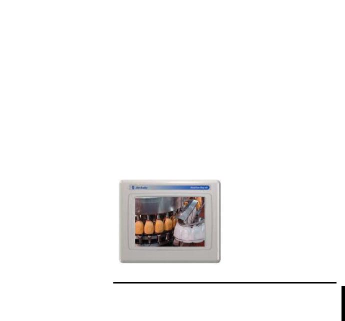
Touch Screen
The PanelView Plus 600 terminals offer an analog resistive touch screen for touch input.
600 Touch Grayscale or Color Terminal
|
The touch screen may be operated with a finger, gloved finger, |
|
IMPORTANT |
||
or plastic stylus device with a minimum tip radius of |
||
|
||
|
||
|
1.3 mm (0.051 in.) to prevent damage to the touch screen. Using |
|
|
any other object or tool may damage the touch screen. |
|
|
|
Publication 2711P-UM001J-EN-P - November 2009 |
15 |
Chapter 1 |
Overview |
|
|
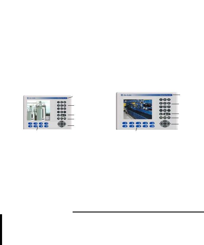
Keypad or Keypad and Touch
The keypad versions of the PanelView Plus 400 and 600 terminals are available with these options:
•400 terminals: grayscale display with keypad or color display with keypad or keypad and touch input
•400 and 600 terminals offer an analog resistive touch screen for touch input.
•600 terminals: color or grayscale displays with either keypad, or keypad and touch input
400 Grayscale with Keypad, or 400 Color with Keypad or Keypad and Touch
 Replaceable ID Label
Numeric Keypad
Backspace and Enter Keys
Tab and Shift Keys
Navigation Keys
8 Programmable Function Keys
600 Grayscale or Color Terminal
with Keypad, or Keypad and Touch Screen
Replaceable ID Label
Numeric Keypad
Backspace and
Enter Keys
Tab and Shift Keys
Navigation Keys
10 Relegendable Programmable Function Keys
Keys |
|
Description |
|
|
|
400 |
F1 through F8 |
Programmable keys that initiate functions |
600 |
F1 through F10 |
on terminal display. Replaceable legends |
|
|
are available for the 600 terminals allowing |
|
|
for custom function key labels. |
|
|
|
Numeric Keypad |
0…9, ., -, Backspace, Enter, Left and Right |
|
|
|
Tab keys, Shift keys |
|
|
|
Navigation Keys |
Use the arrow keys for navigation. |
|
|
|
Use the Alt+arrow keys to activate home, |
|
|
end, page up, and page down functions. |
|
|
|
|
The keypad is designed for finger or gloved finger operation. |
|
IMPORTANT |
||
The touch screen may be operated with a finger, gloved finger, |
||
|
||
|
||
|
or plastic touch screen stylus with a minimum tip radius of |
|
|
1.3 mm (0.051 in.) to prevent damage to the touch screen. |
|
|
Using any other object or tool may damage the touch screen |
|
|
or keypad. |
|
|
|
16 |
Publication 2711P-UM001J-EN-P - November 2009 |
Overview |
Chapter 1 |
|
|
PanelView Plus 700 to 1500 Terminals
This section gives an overview of the PanelView Plus 700, 1000, 1250, 1250H, and 1500 terminals.
•Modular components
•Base-configured unit
•Communication modules
•Logic module, standard or CE
•Power supply, AC or DC
•Display modules
The PanelView Plus 700 to 1500 terminals are HMI devices that offer these features:
•Graphic color-display modules with keypad, touch screen, or keypad and touch screen support
•Analog resistive touch screen
•Ethernet and serial communications
•Modular communication interface for easy add-on capability
•Memory expansion modules for field upgrades to 256 MB RAM and 512 MB CompactFlash
•Power input, AC (85…264V AC) or DC (18…32V DC)
•CompactFlash card slot supports Type 1 CompactFlash cards
•USB ports provide connections for keyboard, mouse, and printer
•Field replaceable bezels
•Same panel cutouts as the PanelView Standard and PanelView Enhanced terminals
•Standard or CE logic module
Publication 2711P-UM001J-EN-P - November 2009 |
17 |

Chapter 1 |
Overview |
|
|
Modular Components
The terminals use modular components allowing for flexible configuration, installation, and upgrades. You can order items as separate components or factory assembled per your configuration.
Communication Module
Logic Module
Display Module
Base-configured Unit
The base-configured unit of the terminal consists of:
•display module (700, 1000, 1250, 1500) with keypad, touch, or keypad and touch input.
•logic module.
|
|
|
Power Input, |
Logic Module |
|
|
AC or DC |
Display Module
Ethernet Port
USB Ports |
Serial Port |
|
CompactFlash Card Slot
The logic module contains:
•24V DC input (18…32V) or AC input (85…264V).
•SDRAM and flash memory, various sizes.
•10/100 BaseT Ethernet port.
•serial RS-232 port for file transfers, printing, and logic controller communications.
•two USB ports for attaching mouse, keyboard, or printer.
•card slot for Type I CompactFlash cards.
•battery-backed real-time clock.
18 |
Publication 2711P-UM001J-EN-P - November 2009 |

Overview |
Chapter 1 |
|
|
Logic Modules and CompactFlash
The logic module is available with or without internal CompactFlash.
The contents of the internal CompactFlash is what differentiates a
PanelView Plus device from a PanelView Plus CE device.
•For the PanelView Plus terminals, the internal CompactFlash contains FactoryTalk View ME software and flash memory.
•For the PanelView Plus CE terminals, the internal CompactFlash contains the open Windows CE operating system,
FactoryTalk View ME software, and flash memory.
The internal CompactFlash is available in different sizes and can be ordered separately or bundled with the logic module.
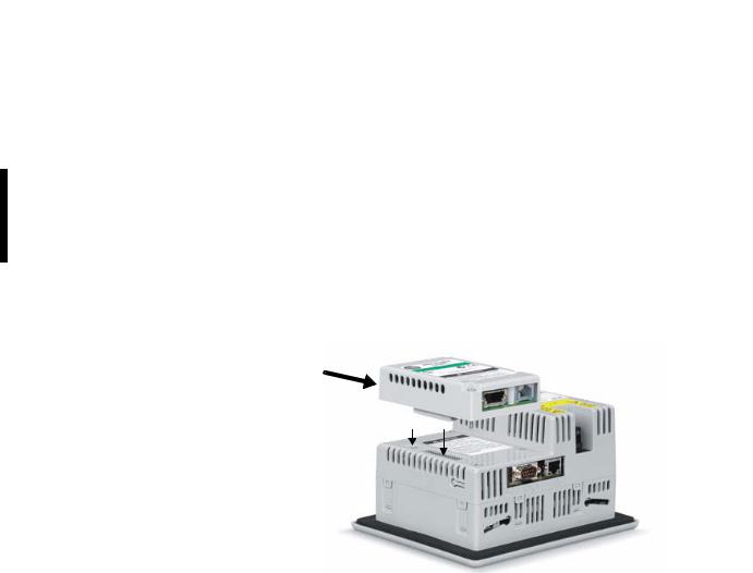
Communication Modules
You can attach a communication module with a network interface to the base-configured unit of the terminal to increase your communication capability with these networks:
•DH+/DH-485
•ControlNet
The communication module installs easily on top of the logic module on the back of the unit.
Communication Module
Publication 2711P-UM001J-EN-P - November 2009 |
19 |

Chapter 1 |
Overview |
|
|
Power Options
The basic configured units of the 700 to 1500 PanelView Plus terminals provide application flexibility with three available power power options:
•AC (85...264V)
•unisolated DC (18...32V)
•isolated DC (18...32V)
For DC applications using AC power, a remote AC-to-DC power supply, cat. no. 2711P-RSACDIN, is available for DIN-rail mounting.
Display Modules
The terminals offer a range of TFT color graphic displays with either keypad, touch screen, or keypad and touch screen support.
•700 (6.5 in.)
•1000 (10.4 in.)
•1250 (12.1 in.)
•1500 (15 in.)
The 700 and 1250 touch displays are available in conformal-coated options. A 1250 high-bright, touch display module is available for outdoor installations. Plus the 1250 and 1500 touch displays offer an integral antiglare overlay.
All displays have common features and firmware providing for easy migration to a larger display. Field-replaceable bezels are also available.
20 |
Publication 2711P-UM001J-EN-P - November 2009 |
Overview |
Chapter 1 |
|
|
Touch Screen
Touch-screen displays are analog resistive and similar except for size.
Replaceable ID Label
 Touch Screen
|
The touch screen may be operated with a finger, gloved finger, |
|
IMPORTANT |
||
or plastic stylus device with a minimum tip radius of |
||
|
||
|
||
|
1.3 mm (0.051 in.) to prevent damage to the touch screen. Using |
|
|
any other object or tool may damage the touch screen. |
|
|
|
Publication 2711P-UM001J-EN-P - November 2009 |
21 |

Chapter 1 |
Overview |
|
|
Programmable Function Keys
(optional custom legends)
Keypad or Keypad and Touch
All displays are similar except for size and the number of function keys available.
Allen-Bradley Label
|
|
|
|
|
|
|
|
|
|
Numeric Keypad |
|
|
|
|
|
|
|
|
|
|
Backspace |
|
|
|
|
|
|
|
|
|
|
and Enter Keys |
|
|
|
|
|
|
|
|
|
|
Tab and Shift Keys |
|
|
|
|
|
|
|
|
|
|
|
|
|
|
|
|
|
|
|
|
|
Esc, CT, Alt Keys |
|
|
|
|
Programmable Function Keys |
|
|
|
|
Navigation Keys |
|
|
|
|
|
|
|
|
|
|||
|
|
|
|
|
|
|
|
|
|
|
|
|
|
|
|
|
|
|
|||
|
|
|
|
(optional custom legends) |
||||||
|
|
|
|
|
|
|||||
|
|
|
|
The keypad is designed for finger or gloved finger operation. |
||||||
|
IMPORTANT |
|||||||||
|
The touch screen may be operated with a finger, gloved finger, |
|||||||||
|
|
|
|
|||||||
|
|
|
|
|||||||
|
|
|
|
or plastic stylus device with a minimum tip radius of |
||||||
|
|
|
|
1.3 mm (0.051 in.) to prevent damage to the touch screen. |
||||||
|
|
|
|
Using any other object or tool may damage the touch screen |
||||||
|
|
|
|
or keypad. |
||||||
|
|
|
|
|
|
|
|
|
|
|
The Kxx and Fxx function keys on the keypad terminals are programmable.
Function Keys |
Description |
|
|
|
|
Function Keys |
Programmable keys that initiate functions |
|
700 |
(F1 through F10, K1 through K12) |
on terminal display. Replaceable legends |
1000 |
(F1 through F16, K1 through K16) |
are available for the terminals allowing for |
1250 |
(F1 through F20, K1 through K20) |
custom function key labels. |
1500 |
(F1 through F20, K1 through K20) |
|
|
|
|
Numeric Keypad |
0…9, ., -, Backspace, Enter, Left and Right |
|
|
|
tab, Shift, Esc, Ctrl, Alt keys. |
|
|
|
Navigation Keys |
Use the arrow keys to move cursor in lists |
|
|
|
and select objects. |
|
|
Alt+arrow key activates home, end, page |
|
|
up, page down functions. |
|
|
|
22 |
Publication 2711P-UM001J-EN-P - November 2009 |

Overview |
Chapter 1 |
|
|
Catalog Number
Configuration
The table shows the catalog number explanation for configured versions of the PanelView Plus and PanelView Plus CE terminals. Not all combinations of options are available for sale.
|
Input |
Display |
Display |
Communication (1) |
Power |
|
Logic Module with |
Special Option(2) |
|
|
Type |
|
Size |
Type |
|
|
Flash and RAM Memory (2) |
|
|
| |
|
| |
| |
| |
| |
|
| |
|
|
2711P- K = Keypad |
4 = 3.5 in. |
C = Color |
PanelView Plus 400 and 600 |
A = AC |
1= Logic Module 64 MB |
K = Conformal-Coated(3) |
|||
|
T = Touch |
6 = 5.5 in. |
M=Grayscale |
5 = RS-232 & USB |
D = DC |
2 |
= Logic Module 128 MB |
M = Marine Certified |
|
|
B = Keypad/Touch |
7 = 6.5 in. |
|
20 = Ethernet, RS-232 & USB plus |
|
6 |
= CE Logic Module with 128 MB |
|
|
|
|
|
|
|
Communication Module Interface |
|
|
|
|
|
|
10 |
= 10.4 in. |
|
|
|
7 |
= CE Logic Module with 256 MB |
|
|
|
12 |
= 12.1 in. |
|
PanelView Plus 700 to 1500 |
|
|
|
|
|
|
15 |
= 15 in. |
|
4 = Ethernet, RS-232 & (2) USB |
|
|
|
|
(1)Additional communication options are available and listed on page 25 in the following section.
(2)Applies to PanelView Plus 700 to 1500 terminals only.
(3)Applies to PanelView Plus 700 and 1250 terminals only.
PanelView Plus Product
Components
Components are available as separate catalog numbers for field installation or replacement.
Display Modules (700 to 1500 only)
Cat. No. |
Description |
|
|
2711P-RDK7C |
700 keypad color display |
|
|
2711P-RDT7C |
700 touch color display |
|
|
2711P-RDT7CM |
700 touch color display, marine certified |
|
|
2711P-RDB7C |
700 keypad and touch color display |
|
|
2711P-RDB7CM |
700 keypad and touch color display, marine certified |
|
|
2711P-RDT7CK |
Conformal-coated 700 touch color display |
|
|
2711P-RDK10C |
1000 keypad color display |
|
|
2711P-RDT10C |
1000 touch color display |
|
|
2711P-RDT10CM |
1000 touch display, marine certified |
|
|
2711P-RDB10C |
1000 keypad and touch color display |
|
|
2711P-RDB10CM |
1000 keypad and touch display, marine certified |
|
|
2711P-RDK12C |
1250 keypad color display |
|
|
2711P-RDT12C |
1250 touch color display |
|
|
2711P-RDT12AG |
1250 touch color display with antiglare overlay |
|
|
2711P-RDT12CK |
Conformal-coated 1250 touch color display |
|
|
2711P-RDT12H |
1250 high-bright touch color display |
|
|
2711P-RDB12C |
1250 keypad and touch color display |
|
|
Publication 2711P-UM001J-EN-P - November 2009 |
23 |

Chapter 1 |
Overview |
|
|
Display Modules (700 to 1500 only)
Cat. No. |
Description |
|
|
|
|
2711P-RDK15C |
1500 keypad color display |
|
|
|
|
2711P-RDT15C |
1500 touch color display |
|
|
|
|
2711P-RDT15AG |
1500 touch color display with antiglare overlay |
|
|
|
|
2711P-RDB15C |
1500 keypad and touch color display |
|
|
|
|
Logic Modules (700 to 1500 only) |
||
|
|
|
Cat. No. |
|
Description |
|
|
|
Standard Logic Modules for PanelView Plus Terminals |
||
|
|
|
2711P-RP |
|
Logic module without flash/RAM memory, DC input |
|
|
|
2711P-RPD |
|
Logic module, without memory, isolated DC input, marine |
|
|
certified |
|
|
|
2711P-RPA |
|
Logic module without flash/RAM memory, AC input, marine |
|
|
certified |
|
|
|
2711P-RP1 |
|
Logic module with 64 MB flash/64 MB RAM, DC input |
|
|
|
2711P-RP1A |
|
Logic module with 64 MB flash/64 MB RAM, AC input, marine |
|
|
certified |
|
|
|
2711P-RP1D |
|
Logic module with 64MB, isolated DC input, marine certified |
|
|
|
2711P-RP2 |
|
Logic module with 128 MB flash/128 MB RAM, DC input (1) |
2711P-RP2A |
|
Logic module with 128 MB flash/128 MB RAM, AC input, marine |
|
|
certified (1) |
2711P-RP2D |
|
Logic module with 128MB, isolated DC input, marine certified (1) |
2711P-RP2DK |
|
Conformal-coated logic module with 128MB, isolated DC input (1) |
2711P-RP2K |
|
Conformal-coated logic module with 128 MB flash/128 MB RAM, |
|
|
DC input (1) |
2711P-RP3 |
|
Logic module with 256 MB flash/256 MB RAM, DC input (1) |
2711P-RP3A |
|
Logic module with 256 MB flash/256 MB RAM, AC input, marine |
|
|
certified (1) |
2711P-RP3D |
|
Logic module with 256MB, isolated DC input, marine certified (1) |
CE Logic Modules for PanelView Plus CE Terminals |
||
|
|
|
2711P-RP6 |
|
CE logic module with 128 MB flash/128 MB RAM, DC input (1) |
2711P-RP6A |
|
CE logic module with 128 MB flash/128 MB RAM, AC input, |
|
|
marine certified (1) |
2711P-RP6D |
|
CE logic module with 128MB, isolated DC input, marine |
|
|
certified(1) |
2711P-RP6DK |
|
CE conformal-coated logic module with 128MB, isolated DC |
|
|
input(1) |
2711P-RP6K |
|
CE conformal-coated logic module with 128 MB flash/128 MB |
|
|
RAM, DC input (1) |
24 |
Publication 2711P-UM001J-EN-P - November 2009 |

Overview Chapter 1
Logic Modules (700 to 1500 only)
Cat. No. |
|
Description |
|
|
|
|
|
|
|
2711P-RP7 |
|
CE logic module with 256 MB flash/256 MB RAM, DC input (1) |
||
2711P-RP7A |
|
CE logic module with 256 MB flash/256 MB RAM, AC input, |
||
|
|
marine certified (1) |
||
2711P-RP7D |
|
CE logic module with 256 MB, isolated DC input, marine |
||
|
|
certified(1) |
|
|
(1) Compatible with ViewPoint Software. |
|
|||
Communication Modules |
|
|||
|
|
|
||
Terminal Type |
Cat. No. |
Description |
||
|
|
|
||
|
2711P-RN3 |
DH-485 communication module |
||
|
|
|
||
400 and 600 |
2711P-RN8 |
DH+ communication module |
||
|
|
|
||
2711P-RN15C |
ControlNet communication module |
|||
|
||||
|
|
|
||
|
2711P-RN22C |
RS-232 isolated communication module |
||
|
|
|
||
|
2711P-RN6 |
DH+/DH-485 communication module |
||
|
|
|
||
|
2711P-RN6K |
Conformal-coated DH+/DH-485 communication |
||
|
|
|
module |
|
700 to 1500 |
|
|
||
2711P-RN15S |
ControlNet communication module, marine |
|||
|
|
|
certified |
|
|
|
|
||
|
2711P-RN15SK |
Conformal-coated ControlNet communication |
||
|
|
|
module |
|
|
|
|
||
Internal Compact Flash |
|
|||
|
|
|
||
Cat. No. |
Description |
|
||
|
|
|||
Internal CompactFlash for Standard Logic Modules |
||||
|
|
|||
2711P-RW1 |
64 MB CompactFlash with FactoryTalk View ME software |
|||
|
|
|||
2711P-RW2 |
128 MB CompactFlash with FactoryTalk View ME software |
|||
|
|
|||
2711P-RW3 |
256 MB CompactFlash with FactoryTalk View ME software |
|||
|
|
|
|
|
Publication 2711P-UM001J-EN-P - November 2009 |
25 |

Chapter 1 |
Overview |
|
|
Internal Compact Flash
Cat. No. |
Description |
|
|
Internal CompactFlash for CE Logic Modules |
|
|
|
2711P-RW6 |
128 MB CompactFlash with FactoryTalk View ME software and the |
|
open Windows CE operating system for the CE logic module |
|
|
2711P-RW7 |
256 MB CompactFlash with FactoryTalk View ME software and the |
|
open Windows CE operating system for the CE logic module |
|
|
2711P-RW8 |
512 MB CompactFlash with FactoryTalk View ME software and the |
|
open Windows CE operating system for the CE logic module |
|
|
RAM Memory (700 to 1500 only) |
|
|
|
Cat. No. |
Description |
|
|
2711P-RR64 |
64 MB SODIMM memory |
|
|
2711P-RR128 |
128 MB SODIMM memory |
|
|
2711P-RR256 |
256 MB SODIMM memory |
|
|
Compact Flash Cards (Blank) |
|
|
|
Cat. No. |
Description |
|
|
2711P-RC2 |
128 MB blank CompactFlash card |
|
|
2711P-RC3 |
256 MB blank CompactFlash card |
|
|
2711P-RC4 |
512 MB blank CompactFlash card |
|
|
2711P-RCH |
CompactFlash to PCMCIA adapter |
|
|
Legend Kits
Cat. No. |
Description |
|
|
2711P-RFK6 |
Replacement legends strips for 600 keypad terminal |
|
|
2711P-RFK7 |
Replacement legends strips for 700 keypad terminal |
|
|
2711P-RFK10 |
Replacement legends strips for 1000 keypad terminal |
|
|
2711P-RFK12 |
Replacement legends strips for 1250 keypad terminal |
|
|
2711P-RFK15 |
Replacement legends strips for 1500 keypad terminal |
|
|
Backlights (700 to 1500 only) |
|
|
|
Cat. No. |
Description |
|
|
2711P-RL7C |
Replacement color backlight for 700 series A and B display modules |
|
|
2711P-RL7C2 |
Replacement color backlight for 700 series C and D display modules |
|
|
2711P-RL10C |
Replacement color backlight for 1000 series A display modules |
|
|
2711P-RL10C2 |
Replacement color backlight for 1000 series B display modules |
|
|
2711P-RL12C |
Replacement color backlight for 1250 series A and B display modules |
|
|
2711P-RL12C2 |
Replacement color backlight for 1250 series C display modules |
|
|
2711P-RL15C |
Replacement color backlight for 1500 series B display modules |
|
|
26 |
Publication 2711P-UM001J-EN-P - November 2009 |

Overview Chapter 1
Replacement Bezels
Cat. No. |
Description |
|
|
2711P-RBK7 |
Replacement bezel for 700 keypad terminal |
|
|
2711P-RBT7 |
Replacement bezel for 700 touch terminal |
|
|
2711P-RBB7 |
Replacement bezel for 700 keypad or keypad/touch terminal |
|
|
2711P-RBK10 |
Replacement bezel for 1000 keypad terminal |
|
|
2711P-RBT10 |
Replacement bezel for 1000 touch terminal |
|
|
2711P-RBB10 |
Replacement bezel for 1000 keypad or keypad/touch terminal |
|
|
2711P-RBK12 |
Replacement bezel for 1250 keypad terminal |
|
|
2711P-RBT12 |
Replacement bezel for 1250 touch terminal |
|
|
2711P-RBT12H |
Replacement bezel for 1250 high-bright touch terminal |
|
|
2711P-RBB12 |
Replacement bezel for 1250 keypad or keypad/touch terminal |
|
|
2711P-RBK15 |
Replacement bezel for 1500 keypad terminal |
|
|
2711P-RBT15 |
Replacement bezel for 1500 touch terminal |
|
|
2711P-RBB15 |
Replacement bezel for 1500 keypad or keypad/touch terminal |
|
|
Protective Antiglare Overlays |
|
|
|
Cat. No.(1) |
Description |
2711P-RGK4 |
Antiglare overlay for PanelView Plus 400 grayscale terminal |
|
|
2711P-RGB4 |
Antiglare overlay for PanelView Plus 400 color keypad/touch terminal |
|
|
2711P-RGK6 |
Antiglare overlay for PanelView Plus 600 keypad or keypad/touch |
|
terminal |
|
|
2711P-RGT6 |
Antiglare overlay for PanelView Plus 600 touch terminal |
|
|
2711P-RGK7 |
Antiglare overlay for PanelView Plus 700 keypad or keypad/touch |
|
terminal |
|
|
2711P-RGT7 |
Antiglare overlay for PanelView Plus 700 touch terminal |
|
|
2711P-RGK10 |
Antiglare overlay for PanelView Plus 1000 keypad or keypad/touch |
|
terminal |
|
|
2711P-RGT10 |
Antiglare overlay for PanelView Plus 1000 touch terminal |
|
|
2711-RGK12 |
Antiglare overlay for PanelView Plus 1250 keypad or keypad/touch |
|
terminal |
|
|
2711P-RGT12 |
Antiglare overlay for PanelView Plus 1250 touch and high-bright touch |
|
terminal |
|
|
2711P-RGK15 |
Antiglare overlay for PanelView Plus 1500 keypad or keypad/touch |
|
terminal |
|
|
2711P-RGT15 |
Antiglare overlay for PanelView Plus 1500 touch terminal |
|
|
(1) All catalog numbers ship with a quantity of three overlays.
Publication 2711P-UM001J-EN-P - November 2009 |
27 |

Chapter 1 |
Overview |
|
|
Adapter Plates
Cat. No. |
Description |
|
|
2711P-RAK4 |
Adapts a PanelView Plus 400 keypad terminal to a PanelView |
|
Standard 550 keypad cutout |
|
|
2711P-RAK6 |
Adapts a PanelView Plus 600 keypad terminal to a PanelView |
|
Standard 600 keypad cutout |
|
|
2711P-RAK7 |
Adapts a PanelView Plus 700 keypad terminal to a PanelView |
|
Standard 900 keypad cutout |
|
|
2711P-RAT7 |
Adapts a PanelView Plus 700 touch terminal to a PanelView Standard |
|
900 touch cutout |
|
|
2711P-RAK10 |
Adapts a PanelView Plus 1000 keypad terminal to a PanelView |
|
1000/1000E keypad cutout |
|
|
2711P-RAT10 |
Adapts a PanelView Plus 1000 touch terminal to a PanelView |
|
1000/1000E touch cutout |
|
|
2711P-RAK12E |
Adapts a PanelView Plus 1250 (or PV1000/1000E) keypad terminal to a |
|
PanelView 1200/1400E keypad cutout |
|
|
2711P-RAT12E2 |
Adapts a PanelView Plus 1250 (or PV1000/1000E) touch terminal to a |
|
PanelView 1200E touch cutout |
|
|
2711P-RAT12E |
Adapts a PanelView Plus 1250 (or PV1000/1000E) touch terminal to a |
|
PanelView 1400E touch cutout |
|
|
2711P-RAK12S |
Adapts a PanelView Plus 1250 (or PV1000/1000E) keypad terminal to a |
|
PanelView Standard 1400 keypad cutout |
|
|
2711P-RAT12S |
Adapts a PanelView Plus 1250 (or PV1000/1000E) touch terminal to a |
|
PanelView Standard 1400 touch cutout |
|
|
2711P-RAK15 |
Adapts a PanelView Plus 1500 keypad or keypad/touch terminal to a |
|
PanelView 1200E/1400E keypad terminal |
|
|
2711P-RAT15 |
Adapts a PanelView Plus 1500 touch terminal to a PanelView 1400E |
|
touch cutout |
|
|
Cables |
|
|
|
Cat. No. |
Description |
|
|
2711-NC13 |
RS-232 operating/programming cable (9-pin D-shell to 9-pin D-shell), |
|
5 m (16.4 ft) |
|
|
2711-NC14 |
RS-232 operating/programming cable (9-pin D-shell to 9-pin D-shell), |
|
10 m (32.7 ft) |
|
|
2711-NC17 |
Remote RS-232 serial cable (9-pin D-shell to 9-pin D-shell) |
|
|
2711-NC21 |
RS-232 operating cable (9-pin D-shell to 8-pin mini DIN), 5 m (16.4 ft) |
|
|
2711-NC22 |
RS-232 operating cable (9-pin D-shell to 8-pin mini DIN), 10 m (32.7 ft) |
|
|
1761-CBL-AS03 |
DH-485 operating cable (6-pin Phoenix to RJ45), 3 m (10 ft) |
|
|
1761-CBL-AS09 |
DH-485 operating cable (6-pin Phoenix to RJ45), 9 m (30 ft) |
|
|
1746-C10 |
DH-485 network interface cable (SDL AMP to RJ45), 1.83 m (6 ft) |
|
|
1746-C11 |
DH-485 network interface cable (SDL AMP to RJ45), .3 m (1 ft.) |
|
|
1784-CP14 |
DH-485 network interface cable (5-pin Phoenix to RJ45) |
|
|
2711P-CBL-EX04 |
Ethernet CAT5 crossover cable, industrial grade, 4.3 m (14 ft) |
|
|
28 |
Publication 2711P-UM001J-EN-P - November 2009 |

Overview |
Chapter 1 |
|
|
Communication Adapters
Cat. No. |
|
Description |
||
|
|
|
|
|
1761-NET-AIC |
|
AIC+ advanced interface converter |
||
|
|
|
|
|
1747-AIC |
|
DH-485 isolated link coupler for use with DH-485 communication |
||
|
|
|
|
modules (2711P-RN3, 2711P-RN6) |
|
|
|
||
Remote AC Power Supply (700 to 1500 only) |
||||
|
|
|
|
|
Cat. No. |
|
Description |
||
|
|
|
||
2711P-RSACDIN |
DIN-rail power supply, AC-to-DC, 85…265V AC, 47…63 Hz |
|||
|
|
|
|
|
Miscellaneous |
|
|
||
|
|
|
|
|
Cat. No. |
|
Description |
||
|
|
|
|
|
2711P-RVT12 |
|
Solar visor for outdoor high-bright 1250 touch screen display modules |
||
|
|
|
|
|
2711P-RY2032 |
|
Replacement battery for 700 to 1500 terminals |
||
|
|
|
|
|
2711P-RTMC |
|
Replacement mounting clips for 700 to 1500 terminals, quantity of 8 |
||
|
|
|
|
|
2711P-RTFC |
|
Replacement mounting levers for 400 and 600 terminals, quantity of 8 |
||
|
|
|
|
|
2711P-RVAC |
|
Replacement AC power terminal block for 400 and 600 terminals |
||
|
|
|
|
|
2711-TBDC |
|
Replacement DC power terminal block for 400 and 600 terminals |
||
|
|
|
||
2711P-RTBDC3 (1) |
Three-position terminal block for DC logic modules, series A to D |
|||
2711P-RTBDC2 (1) |
Two-position terminal block for DC logic modules, series E or later |
|||
2711P-RTBAC3(1) |
Three-position terminal block for all AC logic modules |
|||
(1) |
Catalog numbers ship with a quantity of ten. |
|||
Firmware Upgrade Kits |
||||
|
|
|||
Cat. No. |
|
Description |
||
|
|
|||
2711P-RU310 |
PanelView Plus media kit includes firmware upgrade wizard, one firmware |
|||
|
|
|
license, certificate of authenticity, end user license agreement. |
|
|
|
|
||
2711P-RUA3 |
|
PanelView Plus advanced media kit includes the 2711P-RU310 media kit, |
||
10 |
|
|
PCMCIA to compact flash adapter, and 32 MB CompactFlash card. |
|
|
|
|
||
2711P-RUL01 |
|
Firmware upgrade license kit with one PanelView Plus firmware license.(1) |
||
2711P-RUL05 |
|
Firmware upgrade license kit with five PanelView Plus firmware |
||
|
|
|
licenses.(1) |
|
2711P-RUL10 |
|
Firmware upgrade license kit with 10 PanelView Plus firmware licenses.(1) |
||
2711P-RUL25 |
|
Firmware upgrade license kit with 25 PanelView Plus firmware licenses.(1) |
||
2711P-RUL50 |
|
Firmware upgrade license kit with 50 PanelView Plus firmware licenses.(1) |
||
(1) |
Also includes certificate of authenticity, end user license agreement, installation instructions. |
|||
Publication 2711P-UM001J-EN-P - November 2009 |
29 |

Chapter 1 |
Overview |
|
|
30 |
Publication 2711P-UM001J-EN-P - November 2009 |
Loading...