


 Loading...
User Manual
Micro820 Programmable Controllers
Catalog Numbers 2080-LC20-20QWB, 2080-LC20-20QBB, 2080-LC20-20AWB, 2080-LC20-20QWBR, 2080-
LC20-20QBBR, 2080-LC20-20AWBR

Important User Information
Solid-state equipment has operational characteristics differing from those of electromechanical equipment. Safety Guidelines for the Application, Installation and Maintenance of Solid State Controls (publication SGI-1.1 available from your local Rockwell Automation sales office or online at http://www.rockwellautomation.com/literature/) describes some important differences between solid-state equipment and hard-wired electromechanical devices. Because of this difference, and also because of the wide variety of uses for solid-state equipment, all persons responsible for applying this equipment must satisfy themselves that each intended application of this equipment is acceptable.
In no event will Rockwell Automation, Inc. be responsible or liable for indirect or consequential damages resulting from the use or application of this equipment.
The examples and diagrams in this manual are included solely for illustrative purposes. Because of the many variables and requirements associated with any particular installation, Rockwell Automation, Inc. cannot assume responsibility or liability for actual use based on the examples and diagrams.
No patent liability is assumed by Rockwell Automation, Inc. with respect to use of information, circuits, equipment, or software described in this manual.
Reproduction of the contents of this manual, in whole or in part, without written permission of Rockwell Automation, Inc., is prohibited.
Throughout this manual, when necessary, we use notes to make you aware of safety considerations.
WARNING: Identifies information about practices or circumstances that can cause an explosion in a hazardous environment, which may lead to personal injury or death, property damage, or economic loss.
ATTENTION: Identifies information about practices or circumstances that can lead to personal injury or death, property damage, or economic loss. Attentions help you identify a hazard, avoid a hazard, and recognize the consequence
SHOCK HAZARD: Labels may be on or inside the equipment, for example, a drive or motor, to alert people that dangerous voltage may be present.
BURN HAZARD: Labels may be on or inside the equipment, for example, a drive or motor, to alert people that surfaces may reach dangerous temperatures.
IMPORTANT Identifies information that is critical for successful application and understanding of the product.
Allen-Bradley, Rockwell Software, Rockwell Automation, Micro800, Micro820, Micro830, Micro850, Connected Components Workbench, and TechConnect are trademarks of Rockwell Automation, Inc.
Trademarks not belonging to Rockwell Automation are property of their respective companies.

Preface
Who Should Use this Manual
Purpose of this Manual
Additional Resources
Read this preface to familiarize yourself with the rest of the manual. It provides information concerning:
•who should use this manual
•the purpose of this manual
•related documentation
•supporting information for Micro800™
Use this manual if you are responsible for designing, installing, programming, or troubleshooting control systems that use Micro800 controllers.
You should have a basic understanding of electrical circuitry and familiarity with relay logic. If you do not, obtain the proper training before using this product.
This manual is a reference guide for Micro820 controllers. It describes the procedures you use to install, wire, and troubleshoot your controller. This manual:
•explains how to install and wire your controllers
•gives you an overview of the Micro800 controller system
Refer to the Online Help provided with Connected Components Workbench™ software for more information on programming your Micro800 controller.
These documents contain additional information concerning related Rockwell Automation products.
Resource |
Description |
|
|
Micro800 Plug-in Modules 2080-UM004 |
Information on features, configuration, |
|
installation, wiring, and specifications for the |
|
Micro800 plug-in modules. |
|
|
Micro800 Programmable Controller External AC |
Information on mounting and wiring the optional |
Power Supply Installation Instructions |
external power supply. |
2080-IN001 |
|
|
|
Micro820 Programmable Controllers Installation |
Information on installing, mounting, and wiring |
Instructions, 2080-IN009 |
the Micro820 controller. |
|
|
Micro800 Remote LCD Installation Instructions, |
Information on installing, mounting, and wiring |
2080-IN010 |
the Micro800 Remote LCD module. |
|
|
Micro800 RS232/485 Isolated Serial Port Plug-in |
Information on mounting and wiring the |
Module Wiring Diagrams 2080-WD002 |
Micro800 RS232/485 Isolated Serial Port Plug-in |
|
Module. |
|
|
Micro800 Non-isolated Unipolar Analog Input |
Information on mounting and wiring the |
Plug-in Module Wiring Diagrams 2080-WD003 |
Micro800 Non-isolated Unipolar Analog Input |
|
Plug-in Module. |
|
|
Micro800 Non-isolated Unipolar Analog Output |
Information on mounting and wiring the |
Plug-in Module Wiring Diagrams 2080-WD004 |
Micro800 Non-isolated Unipolar Analog Output |
|
Plug-in Module. |
|
|
Micro800 Non-isolated RTD Plug-in Module |
Information on mounting and wiring the |
Wiring Diagrams 2080-WD005 |
Micro800 Non-isolated RTD Plug-in Module. |
|
|
Rockwell Automation Publication 2080-UM005A-EN-E - December 2013 |
iii |

Preface
Resource |
Description |
|
|
Micro800 Non-isolated Thermocouple Plug-in |
Information on mounting and wiring the |
Module Wiring Diagrams 2080-WD006 |
Micro800 Non-isolated Thermocouple Plug-in |
|
Module. |
|
|
Micro800 Memory Backup and High Accuracy |
Information on mounting and wiring the |
RTC Plug-In Module Wiring Diagrams |
Micro800 Memory Backup and High Accuracy |
2080-WD007 |
RTC Plug-In Module. |
|
|
Micro800 6-Channel Trimpot Analog Input Plug-In |
Information on mounting and wiring the |
Module Wiring Diagrams 2080-WD008 |
Micro800 6-Channel Trimpot Analog Input Plug-In |
|
Module. |
|
|
Micro800 Digital Relay Output Plug-in Module |
Information on mounting and wiring the |
Wiring Diagrams 2080-WD010 |
Micro800 Digital Relay Output Plug-in Module. |
|
|
Micro800 Digital Input, Output, and Combination |
Information on mounting and wiring the |
Plug-in Modules Wiring Diagrams 2080-WD011 |
Micro800 Digital Input, Output, and Combination |
|
Plug-in Modules. |
|
|
Micro800 High Speed Counter Plug-in Module, |
Information on mounting and wiring the High |
2080-WD012 |
Speed Counter Plug-in module. |
|
|
Micro800 DeviceNet Plug-in Module, |
Information on mounting and wiring the |
2080-WD013 |
Micro800 DeviceNet plug-in module. |
|
|
Industrial Automation Wiring and Grounding |
Provides general guidelines for installing a |
Guidelines, publication 1770-4.1 |
Rockwell Automation industrial system. |
|
|
Product Certifications website, http:// |
Provides declarations of conformity, certificates, |
www.rockwellautomation.com/products/ |
and other certification details. |
certification/ |
|
|
|
Application Considerations for Solid-State |
A description of important differences between |
Controls SGI-1.1 |
solid-state programmable controller products |
|
and hard-wired electromechanical devices. |
|
|
National Electrical Code - Published by the |
An article on wire sizes and types for grounding |
National Fire Protection Association of Boston, |
electrical equipment. |
MA. |
|
|
|
Allen-Bradley Industrial Automation Glossary |
A glossary of industrial automation terms and |
AG-7.1 |
abbreviations. |
|
|
You can view or download publications at http://www.rockwellautomation.com/ literature/. To order paper copies of technical documentation, contact your local Rockwell Automation distributor or sales representative.
You can download the latest version of Connected Components Workbench for your Micro800 at the URL below.
http://ab.rockwellautomation.com/Programmable-Controllers/Connected-
Components-Workbench-Software.
iv |
Rockwell Automation Publication 2080-UM005A-EN-E - December 2013 |

|
Table of Contents |
|
Preface |
Who Should Use this Manual . . . . . . . . . . . . . . . . . . . . . . . . . . . . . . . . . . . . . . |
. 7 |
|
Purpose of this Manual . . . . . . . . . . . . . . . . . . . . . . . . . . . . . . . . . . . . . . . . . . . . |
. 7 |
|
Additional Resources . . . . . . . . . . . . . . . . . . . . . . . . . . . . . . . . . . . . . . . . . . . . . . |
. 7 |
|
Chapter 1 |
|
Hardware Overview |
Hardware Features . . . . . . . . . . . . . . . . . . . . . . . . . . . . . . . . . . . . . . . . . . . . . . . . |
. 1 |
|
Inputs and Outputs. . . . . . . . . . . . . . . . . . . . . . . . . . . . . . . . . . . . . . . . . . . . |
. 3 |
|
Embedded microSD (Micro Secure Digital) Card Slot . . . . . . . . . . . . |
. 3 |
|
Embedded RS232/RS485 Serial Port Combo . . . . . . . . . . . . . . . . . . . . |
. 3 |
|
Embedded Ethernet Support . . . . . . . . . . . . . . . . . . . . . . . . . . . . . . . . . . . |
. 4 |
|
Chapter 2 |
|
About Your Controller |
Programming Software for Micro800 Controllers. . . . . . . . . . . . . . . . . . . . |
. 7 |
|
Obtain Connected Components Workbench. . . . . . . . . . . . . . . . . . . . |
. 7 |
|
Use Connected Components Workbench . . . . . . . . . . . . . . . . . . . . . . . |
. 7 |
|
Agency Certifications. . . . . . . . . . . . . . . . . . . . . . . . . . . . . . . . . . . . . . . . . . . . . . |
. 7 |
|
Compliance to European Union Directives. . . . . . . . . . . . . . . . . . . . . . . . . . |
. 7 |
|
EMC Directive. . . . . . . . . . . . . . . . . . . . . . . . . . . . . . . . . . . . . . . . . . . . . . . . |
. 8 |
|
Low Voltage Directive . . . . . . . . . . . . . . . . . . . . . . . . . . . . . . . . . . . . . . . . . |
. 8 |
|
Installation Considerations . . . . . . . . . . . . . . . . . . . . . . . . . . . . . . . . . . . . . . . . |
. 8 |
|
Environment and Enclosure . . . . . . . . . . . . . . . . . . . . . . . . . . . . . . . . . . . |
10 |
|
Preventing Electrostatic Discharge . . . . . . . . . . . . . . . . . . . . . . . . . . . . . |
10 |
|
Safety Considerations . . . . . . . . . . . . . . . . . . . . . . . . . . . . . . . . . . . . . . . . . . . . |
10 |
|
North American Hazardous Location Approval. . . . . . . . . . . . . . . . . |
11 |
|
Disconnecting Main Power. . . . . . . . . . . . . . . . . . . . . . . . . . . . . . . . . . . . |
11 |
|
Safety Circuits . . . . . . . . . . . . . . . . . . . . . . . . . . . . . . . . . . . . . . . . . . . . . . . |
12 |
|
Power Distribution . . . . . . . . . . . . . . . . . . . . . . . . . . . . . . . . . . . . . . . . . . |
12 |
|
Periodic Tests of Master Control Relay Circuit . . . . . . . . . . . . . . . . . |
12 |
|
Power Considerations . . . . . . . . . . . . . . . . . . . . . . . . . . . . . . . . . . . . . . . . . . . . |
12 |
|
Isolation Transformers. . . . . . . . . . . . . . . . . . . . . . . . . . . . . . . . . . . . . . . . |
13 |
|
Power Supply Inrush. . . . . . . . . . . . . . . . . . . . . . . . . . . . . . . . . . . . . . . . . . |
13 |
|
Loss of Power Source . . . . . . . . . . . . . . . . . . . . . . . . . . . . . . . . . . . . . . . . . |
13 |
|
Input States on Power Down . . . . . . . . . . . . . . . . . . . . . . . . . . . . . . . . . . |
14 |
|
Other Types of Line Conditions . . . . . . . . . . . . . . . . . . . . . . . . . . . . . . . |
14 |
|
Preventing Excessive Heat . . . . . . . . . . . . . . . . . . . . . . . . . . . . . . . . . . . . . . . . |
14 |
|
Master Control Relay. . . . . . . . . . . . . . . . . . . . . . . . . . . . . . . . . . . . . . . . . . . . . |
14 |
|
Using Emergency-Stop Switches . . . . . . . . . . . . . . . . . . . . . . . . . . . . . . . |
15 |
|
Schematic (Using IEC Symbols) . . . . . . . . . . . . . . . . . . . . . . . . . . . . . . . |
17 |
|
Schematic (Using ANSI/CSA Symbols). . . . . . . . . . . . . . . . . . . . . . . . |
18 |
|
Chapter 3 |
|
Install Your Controller |
Controller Mounting Dimensions . . . . . . . . . . . . . . . . . . . . . . . . . . . . . . . . . |
19 |
|
Module Spacing . . . . . . . . . . . . . . . . . . . . . . . . . . . . . . . . . . . . . . . . . . . . . . |
20 |
|
DIN Rail Mounting . . . . . . . . . . . . . . . . . . . . . . . . . . . . . . . . . . . . . . . . . . |
20 |
|
Panel Mounting . . . . . . . . . . . . . . . . . . . . . . . . . . . . . . . . . . . . . . . . . . . . . . |
20 |
|
Panel Mounting Dimensions . . . . . . . . . . . . . . . . . . . . . . . . . . . . . . . . . . |
21 |
Rockwell Automation Publication 2080-UM005A-EN-E - December 2013 |
v |

Table of Contents |
|
|
|
Connect the Controller to an EtherNet/IP Network . . . . . . . . . . . . . . . . |
21 |
|
Install the microSD Card . . . . . . . . . . . . . . . . . . . . . . . . . . . . . . . . . . . . . . . . . |
22 |
|
Install the 2080-REMLCD Module. . . . . . . . . . . . . . . . . . . . . . . . . . . . . . . . |
23 |
|
Chapter 4 |
|
Wire Your Controller |
Wiring Requirements and Recommendation . . . . . . . . . . . . . . . . . . . . . . . |
25 |
|
Wire Requirements . . . . . . . . . . . . . . . . . . . . . . . . . . . . . . . . . . . . . . . . . . . |
26 |
|
Use Surge Suppressors . . . . . . . . . . . . . . . . . . . . . . . . . . . . . . . . . . . . . . . . . . . . |
26 |
|
Recommended Surge Suppressors . . . . . . . . . . . . . . . . . . . . . . . . . . . . . . |
28 |
|
Grounding the Controller. . . . . . . . . . . . . . . . . . . . . . . . . . . . . . . . . . . . . . . . . |
29 |
|
Wiring Diagrams . . . . . . . . . . . . . . . . . . . . . . . . . . . . . . . . . . . . . . . . . . . . . . . . . |
29 |
|
Controller I/O Wiring. . . . . . . . . . . . . . . . . . . . . . . . . . . . . . . . . . . . . . . . . . . . |
30 |
|
Minimize Electrical Noise . . . . . . . . . . . . . . . . . . . . . . . . . . . . . . . . . . . . . |
31 |
|
Analog Channel Wiring Guidelines . . . . . . . . . . . . . . . . . . . . . . . . . . . . |
31 |
|
Minimize Electrical Noise on Analog Channels . . . . . . . . . . . . . . . . . |
31 |
|
Grounding Your Analog Cable . . . . . . . . . . . . . . . . . . . . . . . . . . . . . . . . |
32 |
|
Wiring Examples . . . . . . . . . . . . . . . . . . . . . . . . . . . . . . . . . . . . . . . . . . . . . |
32 |
|
Wiring Analog Channels. . . . . . . . . . . . . . . . . . . . . . . . . . . . . . . . . . . . . . . . . . |
33 |
|
Chapter 5 |
|
Communication Connections |
Overview . . . . . . . . . . . . . . . . . . . . . . . . . . . . . . . . . . . . . . . . . . . . . . . . . . . . . . . . |
37 |
|
Supported Communication Protocols. . . . . . . . . . . . . . . . . . . . . . . . . . . . . . |
37 |
|
Modbus RTU . . . . . . . . . . . . . . . . . . . . . . . . . . . . . . . . . . . . . . . . . . . . . . . . |
37 |
|
Modbus/TCP Client/Server. . . . . . . . . . . . . . . . . . . . . . . . . . . . . . . . . . . |
38 |
|
CIP Symbolic Client/Server . . . . . . . . . . . . . . . . . . . . . . . . . . . . . . . . . . . |
38 |
|
CIP Client Messaging . . . . . . . . . . . . . . . . . . . . . . . . . . . . . . . . . . . . . . . . . |
39 |
|
ASCII . . . . . . . . . . . . . . . . . . . . . . . . . . . . . . . . . . . . . . . . . . . . . . . . . . . . . . . |
40 |
|
CIP Communications Pass-thru . . . . . . . . . . . . . . . . . . . . . . . . . . . . . . . . . . . |
40 |
|
Examples of Supported Architectures. . . . . . . . . . . . . . . . . . . . . . . . . . . |
40 |
|
Use Modems with Micro800 Controllers. . . . . . . . . . . . . . . . . . . . . . . . . . . |
41 |
|
Making a DF1 Point-to-Point Connection. . . . . . . . . . . . . . . . . . . . . . |
41 |
|
Construct Your Own Modem Cable . . . . . . . . . . . . . . . . . . . . . . . . . . . |
41 |
|
Configure Serial Port . . . . . . . . . . . . . . . . . . . . . . . . . . . . . . . . . . . . . . . . . . . . . |
42 |
|
Configure CIP Serial Driver . . . . . . . . . . . . . . . . . . . . . . . . . . . . . . . . . . . |
43 |
|
Configure Modbus RTU . . . . . . . . . . . . . . . . . . . . . . . . . . . . . . . . . . . . . . |
45 |
|
Configure ASCII . . . . . . . . . . . . . . . . . . . . . . . . . . . . . . . . . . . . . . . . . . . . . |
47 |
|
Configure Ethernet Settings . . . . . . . . . . . . . . . . . . . . . . . . . . . . . . . . . . . . . . . |
48 |
|
Ethernet Host Name. . . . . . . . . . . . . . . . . . . . . . . . . . . . . . . . . . . . . . . . . . |
49 |
|
Chapter 6 |
|
Program Execution in Micro800 |
Overview of Program Execution . . . . . . . . . . . . . . . . . . . . . . . . . . . . . . . . . . . |
51 |
|
Execution Rules . . . . . . . . . . . . . . . . . . . . . . . . . . . . . . . . . . . . . . . . . . . . . . |
52 |
|
Controller Load and Performance Considerations . . . . . . . . . . . . . . . . . . |
52 |
|
Periodic Execution of Programs . . . . . . . . . . . . . . . . . . . . . . . . . . . . . . . . |
53 |
vi |
Rockwell Automation Publication 2080-UM005A-EN-E - December 2013 |

|
|
Chapter 1 |
|
Power Up and First Scan. . . . . . . . . . . . . . . . . . . . . . . . . . . . . . . . . . . . . . |
. . . . 53 |
|
Variable Retention . . . . . . . . . . . . . . . . . . . . . . . . . . . . . . . . . . . . . . . . |
. . . 54 |
|
Memory Allocation . . . . . . . . . . . . . . . . . . . . . . . . . . . . . . . . . . . . . . . . . . . |
. . . 54 |
|
Guidelines and Limitations for Advanced Users . . . . . . . . . . . . . . . . . |
. . . 54 |
|
Chapter 7 |
|
Controller Security |
Exclusive Access. . . . . . . . . . . . . . . . . . . . . . . . . . . . . . . . . . . . . . . . . . . . . . . |
. . . 57 |
|
Password Protection. . . . . . . . . . . . . . . . . . . . . . . . . . . . . . . . . . . . . . . . . . . |
. . . 57 |
|
Compatibility. . . . . . . . . . . . . . . . . . . . . . . . . . . . . . . . . . . . . . . . . . . . . . . . . |
. . . 57 |
|
Work with a Locked Controller . . . . . . . . . . . . . . . . . . . . . . . . . . . . . . . . |
. . . 58 |
|
Upload from a Password-Protected Controller . . . . . . . . . . . . . . . |
. . . 58 |
|
Debug a Password-Protected Controller. . . . . . . . . . . . . . . . . . . . . |
. . . 59 |
|
Download to a Password-Protected Controller. . . . . . . . . . . . . . . |
. . . 59 |
|
Transfer Controller Program and Lock Receiving Controller. . |
. . . 59 |
|
Back Up a Password-Protected Controller . . . . . . . . . . . . . . . . . . . |
. . . 60 |
|
Configure Controller Password . . . . . . . . . . . . . . . . . . . . . . . . . . . . . . . . |
. . . 60 |
|
Recover from a Lost Password . . . . . . . . . . . . . . . . . . . . . . . . . . . . . . . . . . |
. . . 61 |
|
Chapter 8 |
|
Using the Micro800 Remote LCD |
Overview . . . . . . . . . . . . . . . . . . . . . . . . . . . . . . . . . . . . . . . . . . . . . . . . . . . . . |
. . . 63 |
|
USB Mode . . . . . . . . . . . . . . . . . . . . . . . . . . . . . . . . . . . . . . . . . . . . . . . . . . . |
. . . 64 |
|
Text Display Mode . . . . . . . . . . . . . . . . . . . . . . . . . . . . . . . . . . . . . . . . . . . . |
. . . 65 |
|
Startup Screen . . . . . . . . . . . . . . . . . . . . . . . . . . . . . . . . . . . . . . . . . . . . |
. . . 65 |
|
Navigate the Remote LCD . . . . . . . . . . . . . . . . . . . . . . . . . . . . . . . . . |
. . . 66 |
|
Main Menu . . . . . . . . . . . . . . . . . . . . . . . . . . . . . . . . . . . . . . . . . . . . . . . |
. . . 66 |
|
User-defined Screens. . . . . . . . . . . . . . . . . . . . . . . . . . . . . . . . . . . . . . . |
. . . 69 |
|
Backup and Restore . . . . . . . . . . . . . . . . . . . . . . . . . . . . . . . . . . . . . . . . . . . |
. . . 71 |
|
Hardware Features, Installation, and Specifications . . . . . . . . . . . . . . |
. . . 71 |
|
Chapter 9 |
|
Using microSD Cards |
Overview . . . . . . . . . . . . . . . . . . . . . . . . . . . . . . . . . . . . . . . . . . . . . . . . . . . . . |
. . . 73 |
|
Project Backup and Restore . . . . . . . . . . . . . . . . . . . . . . . . . . . . . . . . . . . . |
. . . 73 |
|
Backup and Restore Directory Structure. . . . . . . . . . . . . . . . . . . . . |
. . . 75 |
|
Powerup Settings in ConfigMeFirst.txt. . . . . . . . . . . . . . . . . . . . . . |
. . . 76 |
|
General Configuration Rules in ConfigMeFirst.txt . . . . . . . . . . . |
. . . 77 |
|
ConfigMeFirst.txt Errors. . . . . . . . . . . . . . . . . . . . . . . . . . . . . . . . . . . |
. . . 77 |
|
Datalog. . . . . . . . . . . . . . . . . . . . . . . . . . . . . . . . . . . . . . . . . . . . . . . . . . . . . . . |
. . . 78 |
|
Datalog Directory Structure . . . . . . . . . . . . . . . . . . . . . . . . . . . . . . . |
. . . 79 |
|
Datalog Function (DLG) Block . . . . . . . . . . . . . . . . . . . . . . . . . . . . |
. . . 80 |
|
Recipe. . . . . . . . . . . . . . . . . . . . . . . . . . . . . . . . . . . . . . . . . . . . . . . . . . . . . . . . |
. . . 83 |
|
Recipe Directory Structure . . . . . . . . . . . . . . . . . . . . . . . . . . . . . . . . |
. . . 84 |
|
Recipe Function (RCP) Block . . . . . . . . . . . . . . . . . . . . . . . . . . . . . . |
. . . 84 |
|
Quickstart Projects for Datalog and Recipe Function Blocks . . . . . . |
. . . 87 |
|
Use the Datalog Feature . . . . . . . . . . . . . . . . . . . . . . . . . . . . . . . . . . . |
. . . 88 |
Rockwell Automation Publication 2080-UM005A-EN-E - December 2013 |
vii |
|

Table of Contents |
|
|
|
Use the Recipe Feature . . . . . . . . . . . . . . . . . . . . . . . . . . . . . . . . . . . . . . . |
. 94 |
|
Appendix A |
|
Specifications |
. . . . . . . . . . . . . . . . . . . . . . . . . . . . . . . . . . . . . . . . . . . . . . . . . . . . . . . . . . . . . . . . |
101 |
|
Appendix B |
|
Troubleshooting |
Status Indicators on the Controller . . . . . . . . . . . . . . . . . . . . . . . . . . . . . . . |
111 |
|
Normal Operation. . . . . . . . . . . . . . . . . . . . . . . . . . . . . . . . . . . . . . . . . . . |
112 |
|
Error Conditions . . . . . . . . . . . . . . . . . . . . . . . . . . . . . . . . . . . . . . . . . . . . . . . . |
112 |
|
Error codes . . . . . . . . . . . . . . . . . . . . . . . . . . . . . . . . . . . . . . . . . . . . . . . . . . . . . |
113 |
|
Controller Error Recovery Model. . . . . . . . . . . . . . . . . . . . . . . . . . . . . . . . . |
119 |
|
Calling Rockwell Automation for Assistance. . . . . . . . . . . . . . . . . . . . . . . |
120 |
|
Appendix C |
|
Quickstarts |
Flash Upgrade Your Micro800 Firmware . . . . . . . . . . . . . . . . . . . . . . . . . . |
121 |
|
Establish Communications between RSLinx and a Micro820 Controller |
|
|
through USB Port on 2080-REMLCD. . . . . . . . . . . . . . . . . . . . . . . . . . . . |
124 |
|
Configure Controller Password. . . . . . . . . . . . . . . . . . . . . . . . . . . . . . . . . . . |
128 |
|
Set Controller Password. . . . . . . . . . . . . . . . . . . . . . . . . . . . . . . . . . . . . . |
129 |
|
Change Password . . . . . . . . . . . . . . . . . . . . . . . . . . . . . . . . . . . . . . . . . . . . |
130 |
|
Clear Password . . . . . . . . . . . . . . . . . . . . . . . . . . . . . . . . . . . . . . . . . . . . . . |
131 |
|
Forcing I/Os . . . . . . . . . . . . . . . . . . . . . . . . . . . . . . . . . . . . . . . . . . . . . . . . . . . . |
132 |
|
Checking if Forces (locks) are Enabled. . . . . . . . . . . . . . . . . . . . . . . . . |
132 |
|
I/O Forces After a Power Cycle . . . . . . . . . . . . . . . . . . . . . . . . . . . . . . . |
133 |
|
Appendix D |
|
IPID Function Block |
How to Autotune . . . . . . . . . . . . . . . . . . . . . . . . . . . . . . . . . . . . . . . . . . . . . . . |
137 |
|
How Autotune Works . . . . . . . . . . . . . . . . . . . . . . . . . . . . . . . . . . . . . . . |
138 |
|
Troubleshooting an Autotune Process. . . . . . . . . . . . . . . . . . . . . . . . . . . . . |
139 |
|
PID Application Example . . . . . . . . . . . . . . . . . . . . . . . . . . . . . . . . . . . . . . . . |
140 |
|
PID Code Sample . . . . . . . . . . . . . . . . . . . . . . . . . . . . . . . . . . . . . . . . . . . |
141 |
|
Appendix F |
|
Modbus Mapping for Micro800 |
Modbus Mapping . . . . . . . . . . . . . . . . . . . . . . . . . . . . . . . . . . . . . . . . . . . . . . . |
143 |
|
Endian Configuration. . . . . . . . . . . . . . . . . . . . . . . . . . . . . . . . . . . . . . . . |
143 |
|
Mapping Address Space and supported Data Types . . . . . . . . . . . . . |
143 |
|
Example 1, PanelView Component HMI (Master) to Micro800 |
|
|
(Slave) . . . . . . . . . . . . . . . . . . . . . . . . . . . . . . . . . . . . . . . . . . . . . . . . . . . . . . |
144 |
|
Example 2, Micro800 (Master) to PowerFlex 4M Drive (Slave) . . |
145 |
|
Performance. . . . . . . . . . . . . . . . . . . . . . . . . . . . . . . . . . . . . . . . . . . . . . . . . |
148 |
|
Index |
|
viii |
Rockwell Automation Publication 2080-UM005A-EN-E - December 2013 |
Chapter 1
Hardware Overview
Hardware Features
This chapter provides an overview of the Micro820 hardware features. It has the following topics:
Topic |
Page |
|
|
Hardware Features |
1 |
|
|
Embedded microSD (Micro Secure Digital) Card Slot |
3 |
|
|
Embedded RS232/RS485 Serial Port Combo |
3 |
|
|
Embedded Ethernet Support |
4 |
|
|
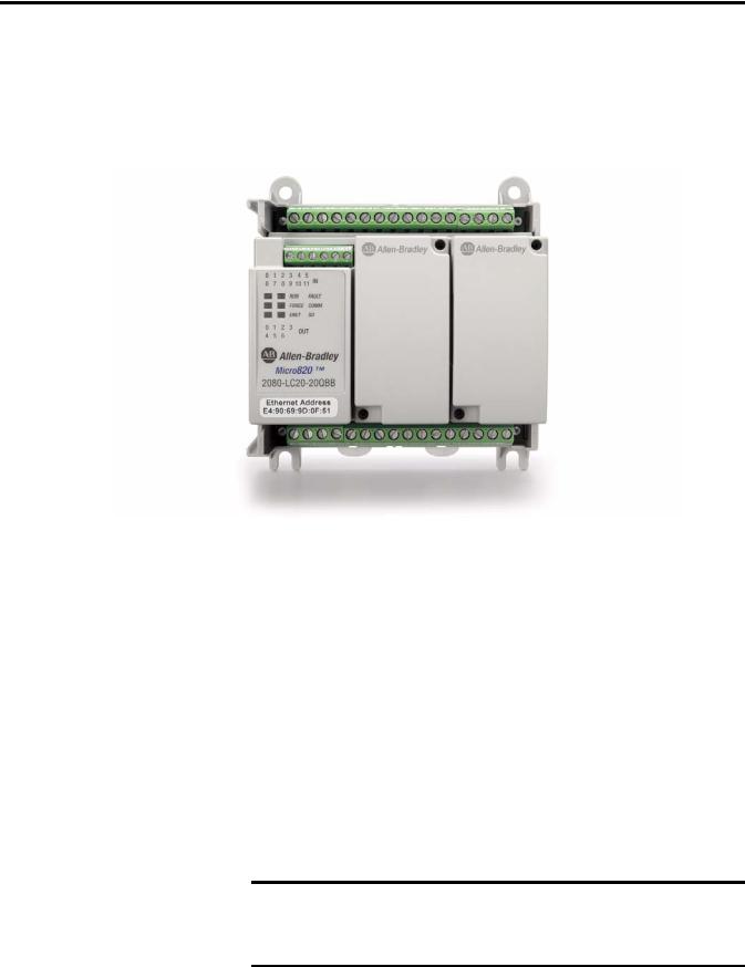
Micro820 controllers are 20-point economical brick style controllers with embedded inputs and outputs. These controllers can accommodate up to two plug-in modules and can connect to a remote LCD (2080-REMLCD) for configuring. The Micro820 controller also has a microSD™ card slot for project backup and restore, and datalog and recipe.
IMPORTANT The Micro820 controller supports all Micro800 plug-in modules, except for the 2080-MEMBAK-RTC.
For more information, see Micro800 Plug-in Modules User, publication 2080-UM004.
Rockwell Automation Publication 2080-UM005A-EN-E - December 2013 |
1 |
Chapter 1 Hardware Overview
For information on the REMLCD module, see Using the Micro800 Remote
LCD on page 63.
The controller also accommodates any class 2 rated 24V DC output power supply that meets minimum specifications such as the optional Micro800 power supply.
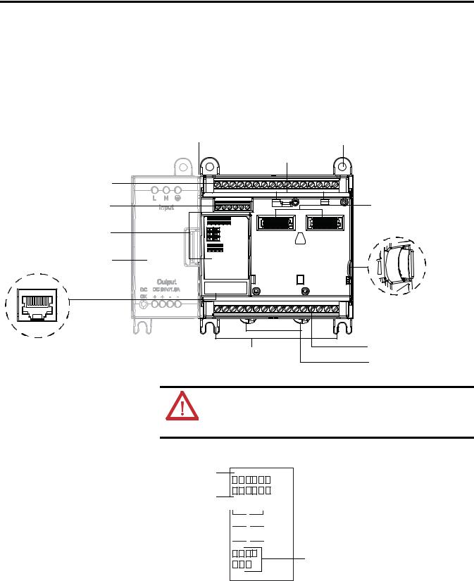
Micro820 Controllers
Optional power supply slot |
Mounting screw hole |
|
|
Plug-in latch |
|
Removable/fixed terminal blocks |
|
|
RS232/RS485 non-isolated |
|
40-pin high-speed plug-in |
|
connector slot |
|
combo serial ports |
|
|
|
|
|
Status indicators |
|
|
Power supply |
|
|
|
|
microSD (Micro |
|
|
Secure Digital) |
|
|
card slot |
RJ-45 Ethernet |
|
46206 |
|
Removable/fixed terminal blocks |
|
connector port |
Mounting feet |
|
|
|
|
|
|
DIN rail mounting latch |
ATTENTION: Removable terminal blocks are available on catalog numbers that end in R (for example, 2080-LC20-20QBBR). Fixed terminal blocks are available on catalog numbers that do not end in R (for example, 2080-LC20-20QBB).
Status Indicators
Input status 

Run status 

 Fault status
Force status

 Comm status
ENET status

 SD status
Output status
46207
See Troubleshooting on page 111 for descriptions of status indicator operation.
2 |
Rockwell Automation Publication 2080-UM005A-EN-E - December 2013 |
|
|
|
|
|
|
|
|
|
|
Hardware Overview |
Chapter 1 |
|
|
|
|
|
|
|
|
|
|
|
|
|
|
|
|
|
Inputs and Outputs |
|
|
|
|
|
|
|||
Number and Types of Inputs/Outputs for Micro820 Controllers |
|
|
|
|
|
|
||||||
|
|
|
|
|
|
|
|
|
|
|
|
|
Controller |
Catalogs |
Inputs |
|
|
Outputs |
|
|
Analog Out |
Analog In |
|
PWM |
|
Family |
|
|
|
|
|
|
|
|
0…10V DC |
0…10V (shared |
|
Support |
|
120V AC |
120 / |
24V DC |
Relay |
|
24V DC |
24V DC |
|
||||
|
|
|
|
with DC In) |
|
|
||||||
|
|
|
240V AC |
|
|
|
Source |
Sink |
|
|
|
|
|
|
|
|
|
|
|
|
|
|
|||
|
|
|
|
|
|
|
|
|
|
|
|
|
Micro820 |
2080-LC20-20QBB |
– |
– |
12 |
|
|
7 |
– |
1 |
4 |
|
1 |
|
|
|
|
|
|
|
|
|
|
|
|
|
|
2080-LC20-20QWB |
– |
– |
12 |
7 |
|
– |
– |
1 |
4 |
|
– |
|
|
|
|
|
|
|
|
|
|
|
|
|
|
2080-LC20-20AWB |
8 |
– |
4 |
7 |
|
– |
– |
1 |
4 |
|
– |
|
|
|
|
|
|
|
|
|
|
|
|
|
|
2080-LC20-20QBBR |
– |
– |
12 |
– |
|
7 |
– |
1 |
4 |
|
1 |
|
|
|
|
|
|
|
|
|
|
|
|
|
|
2080-LC20-20QWBR |
– |
– |
12 |
7 |
|
– |
– |
1 |
4 |
|
– |
|
|
|
|
|
|
|
|
|
|
|
|
|
|
2080-LC20-20AWBR |
8 |
– |
4 |
7 |
|
|
– |
1 |
4 |
|
– |
|
|
|
|
|
|
|
|
|
|
|
|
|
Embedded microSD (Micro Secure Digital) Card Slot
Micro820 controllers support microSD cards through an embedded microSD card slot. It supports Class 6 and 10 SDSC and SDHC microSD cards, with FAT32/16 formats, 32 GB maximum size. Industrial grade cards such as Swissbit S-200u/S300u are recommended. The microSD file system supports only one file partition. Class 4 cards are not supported.
The microSD card is primarily used for project backup and restore, as well as datalog and recipe functions. It can also be used to configure powerup settings (such as controller mode, IP address, and so on) through an optional ConfigMeFirst.txt file.
For more information, see Using microSD Cards on page 73.
To help you troubleshoot microSD card-related errors, see Troubleshooting on page 111.
Embedded RS232/RS485 Serial Port Combo
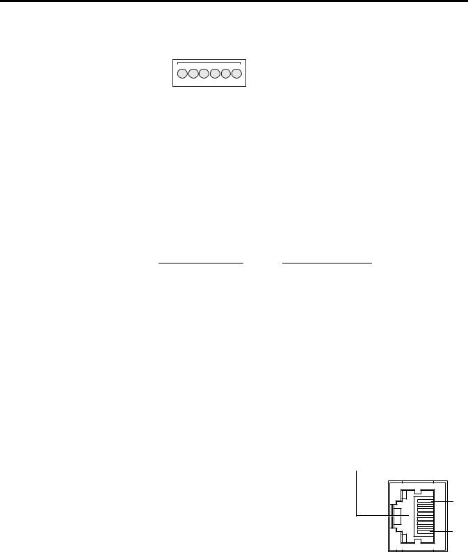
The Micro820 controller supports an embedded non-isolated RS232/RS485 combo communications port. Only one port (RS232 or RS485) can work at any given time. The baud rate of this port supports up to 38.4 K.
The communication port uses a 6-pin 3.5 mm terminal block with pin definition shown in the following table.
IMPORTANT Serial port cables should not exceed 3 m length.
Rockwell Automation Publication 2080-UM005A-EN-E - December 2013 |
3 |
Chapter 1 Hardware Overview
RS232/RS485 Serial Port Pin Definition
D+ |
|
G |
|
Tx |
|
1 |
2 |
3 |
4 |
5 |
6 |
|
D- |
|
Rx |
|
G |
Pin |
Definition |
RS485 |
RS232 |
|
|
Example |
Example |
|
|
|
|
1 |
RS485+ |
RS485+ |
(not used) |
|
|
|
|
2 |
RS485- |
RS485- |
(not used) |
|
|
|
|
3 |
GND |
GND |
GND |
|
|
|
|
4 |
RS232 input (receiver) |
(not used) |
RxD |
|
|
|
|
5 |
RS232 output (driver) |
(not used) |
TxD |
|
|
|
|
6 |
GND |
GND |
GND |
|
|
|
|
The communication port (both RS232 and RS485) are non-isolated. The signal ground of the port is not isolated to the logic ground of the controller.
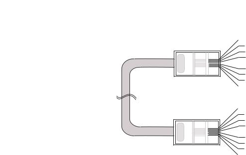
The RS232 port supports connection to the Micro800 Remote LCD module (2080-REMLCD).
REMLCD to Micro820 Serial Port Terminal Block Wiring
REMLCD Serial Port |
|
|
Micro820 Serial Port |
||
Terminal Block |
|
|
Terminal Block |
||
|
|
|
|
|
|
Signal |
Pin |
|
|
Pin |
Signal |
|
number |
|
|
number |
|
|
|
|
|
|
|
RS232 TX |
1 |
<-------- |
> |
4 |
RX RS232 |
|
|
|
|
|
|
RS232 RX |
2 |
<-------- |
> |
5 |
TX RS232 |
|
|
|
|
|
|
RS232 G |
3 |
<-------- |
> |
6 |
G RS232 |
|
|
|
|
|
|
Embedded Ethernet Support
A 10/100 Base-T Port is available for connection to an Ethernet network through any standard RJ-45 Ethernet cable.
RJ-45 Ethernet Port Pin Mapping
Contact |
Signal |
Direction |
Primary |
Number |
|
|
Function |
|
|
|
|
1 |
TX+ |
OUT |
Transmit data + |
|
|
|
|
2 |
TX- |
OUT |
Transmit data - |
|
|
|
|
3 |
RX+ |
IN |
Receive data + |
|
|
|
|
4 |
– |
– |
– |
|
|
|
|
5 |
– |
– |
– |
|
|
|
|
6 |
RX- |
IN |
Receive data - |
|
|
|
|
7 |
– |
– |
– |
|
|
|
|
8 |
– |
– |
– |
|
|
|
|
RJ-45 connector
1 |
8 |
46210 |
4 |
Rockwell Automation Publication 2080-UM005A-EN-E - December 2013 |
Hardware Overview |
Chapter 1 |
|
|
Ethernet port pin-to-pin connection
1 |
white-orange |
|
2 |
orange |
|
3 |
white-green |
|
4 |
blue |
|
5 |
white-blue |
|
6 |
green |
|
7 |
white-brown |
|
8 |
brown |
|
1 |
white-orange |
|
2 |
orange |
|
3 |
white-green |
|
4 |
blue |
|
5 |
white-blue |
|
6 |
green |
|
7 |
white-brown |
|
8 |
brown |
46223 |
See Troubleshooting on page 111 for descriptions of ENET status indicator.
Rockwell Automation Publication 2080-UM005A-EN-E - December 2013 |
5 |

Chapter 1 Hardware Overview
Notes:
6 |
Rockwell Automation Publication 2080-UM005A-EN-E - December 2013 |

Chapter 2
About Your Controller
Programming Software for Micro800 Controllers
Connected Components Workbench is a set of collaborative tools supporting Micro800 controllers. It is based on Rockwell Automation and Microsoft Visual Studio technology and offers controller programming, device configuration and integration with HMI editor. Use this software to program your controllers, configure your devices and design your operator interface applications.
Connected Components Workbench provides a choice of IEC 61131-3 programming languages (ladder diagram, function block diagram, structured text) with user defined function block support that optimizes machine control.
Obtain Connected Components Workbench
A free download is available at:
http://ab.rockwellautomation.com/Programmable-Controllers/Connected- Components-Workbench-Software
Agency Certifications
Compliance to European Union Directives
Use Connected Components Workbench
To help you program your controller through the Connected Components Workbench software, you can refer to the Connected Components Workbench Online Help (it comes with the software).
•UL Listed Industrial Control Equipment, certified for US and Canada. UL Listed for Class I, Division 2 Group A,B,C,D Hazardous Locations, certified for U.S. and Canada.
•CE marked for all applicable directives
•C-Tick marked for all applicable acts
•KC - Korean Registration of Broadcasting and Communications Equipment, compliant with: Article 58-2 of Radio Waves Act, Clause 3.
This product has the CE mark and is approved for installation within the European Union and EEA regions. It has been designed and tested to meet the following directives.
Rockwell Automation Publication 2080-UM005A-EN-E - December 2013 |
7 |

Chapter 2 About Your Controller
EMC Directive
This product is tested to meet Council Directive 2004/108/EC Electromagnetic Compatibility (EMC) and the following standards, in whole or in part, documented in a technical construction file:
•EN 61131-2; Programmable Controllers (Clause 8, Zone A & B)
•EN 61131-2; Programmable Controllers (Clause 11)
•EN 61000-6-4
EMC - Part 6-4: Generic Standards - Emission Standard for Industrial Environments
•EN 61000-6-2
EMC - Part 6-2: Generic Standards - Immunity for Industrial Environments
This product is intended for use in an industrial environment.
Low Voltage Directive
This product is tested to meet Council Directive 2006/95/ECLow Voltage, by applying the safety requirements of EN 61131-2 Programmable Controllers, Part 2 - Equipment Requirements and Tests.
For specific information required by EN 61131-2, see the appropriate sections in this publication, as well as the following Allen-Bradley publications:
•Industrial Automation Wiring and Grounding Guidelines for Noise Immunity, publication 1770-4.1.
•Guidelines for Handling Lithium Batteries, publication AG-5.4
•Automation Systems Catalog, publication B115
Installation Considerations Most applications require installation in an industrial enclosure (Pollution Degree 2(1)) to reduce the effects of electrical interference (Over Voltage
Category II(2)) and environmental exposure.
Locate your controller as far as possible from power lines, load lines, and other sources of electrical noise such as hard-contact switches, relays, and AC motor drives. For more information on proper grounding guidelines, see the Industrial Automation Wiring and Grounding Guidelines publication 1770-4.1.
(1)Pollution Degree 2 is an environment where normally only non-conductive pollution occurs except that occassionally temporary conductivity caused by condensation shall be expected.
(2)Overvoltage Category II is the load level section of the electrical distribution system. At this level, transient voltages are controlled and do not exceed the impulse voltage capability of the products insulation.
8 |
Rockwell Automation Publication 2080-UM005A-EN-E - December 2013 |
About Your Controller |
Chapter 2 |
|
|
WARNING: When used in a Class I, Division 2, hazardous location, this equipment must be mounted in a suitable enclosure with proper wiring method that complies with the governing electrical codes.
WARNING: If you connect or disconnect the serial cable with power applied to this module or the serial device on the other end of the cable, an electrical arc can occur. This could cause an explosion in hazardous location installations. Be sure that power is removed or the area is nonhazardous before proceeding.
WARNING: The local programming terminal port is intended for temporary use only and must not be connected or disconnected unless the area is assured to be nonhazardous.
WARNING: Exposure to some chemicals may degrade the sealing properties of materials used in the Relays. It is recommended that the User periodically inspect these devices for any degradation of properties and replace the module if degradation is found.
WARNING: If you insert or remove the plug-in module while backplane power is on, an electrical arc can occur. This could cause an explosion in hazardous location installations. Be sure that power is removed or the area is nonhazardous before proceeding.
WARNING: When you connect or disconnect the Removable Terminal Block (RTB) with field side power applied, an electrical arc can occur. This could cause an explosion in hazardous location installations.
WARNING: Be sure that power is removed or the area is nonhazardous before proceeding.
ATTENTION: To comply with the CE Low Voltage Directive (LVD), this equipment must be powered from a source compliant with the following: Safety Extra Low Voltage (SELV) or Protected Extra Low Voltage (PELV).
ATTENTION: To comply with UL restrictions, this equipment must be powered from a Class 2 source.
ATTENTION: Be careful when stripping wires. Wire fragments that fall into the controller could cause damage. Once wiring is complete, make sure the controller is free of all metal fragments.
ATTENTION: Electrostatic discharge can damage semiconductor devices inside the module. Do not touch the connector pins or other sensitive areas.
ATTENTION: The serial cables are not to exceed 3.0 m (9.84 ft). ATTENTION: Do not wire more than 2 conductors on any single terminal.
ATTENTION: Do not remove the Removable Terminal Block (RTB) until power is removed.
Rockwell Automation Publication 2080-UM005A-EN-E - December 2013 |
9 |
Chapter 2 About Your Controller
Environment and Enclosure
This equipment is intended for use in a Pollution Degree 2 industrial environment, in overvoltage Category II applications (as defined in IEC 60664-1), at altitudes up to 2000 m (6562 ft) without derating.
This equipment is considered Group 1, Class A industrial equipment according to IEC/CISPR 11. Without appropriate precautions, there may be difficulties with electromagnetic compatibility in residential and other environments due to conducted and radiated disturbances.
This equipment is supplied as open-type equipment. It must be mounted within an enclosure that is suitably designed for those specific environmental conditions that will be present and appropriately designed to prevent personal injury resulting from accessibility to live parts. The enclosure must have suitable flame-retardant properties to prevent or minimize the spread of flame, complying with a flame spread rating of 5VA, V2, V1, V0 (or equivalent) if non-metallic. The interior of the enclosure must be accessible only by the use of a tool. Subsequent sections of this publication may contain additional information regarding specific enclosure type ratings that are required to comply with certain product safety certifications.
In addition to this publication, see:
•Industrial Automation Wiring and Grounding Guidelines, Rockwell Automation publication 1770-4.1, for additional installation requirements.
•NEMA Standard 250 and IEC 60529, as applicable, for explanations of the degrees of protection provided by different types of enclosure.
Preventing Electrostatic Discharge
This equipment is sensitive to electrostatic discharge, which can cause internal damage and affect normal operation. Follow these guidelines when you handle this equipment:
•Touch a grounded object to discharge potential static.
•Wear an approved grounding wriststrap.
•Do not touch connectors or pins on component boards.
•Do not touch circuit components inside the equipment.
•Use a static-safe workstation, if available.
•Store the equipment in appropriate static-safe packaging when not in use.
Safety Considerations
Safety considerations are an important element of proper system installation. Actively thinking about the safety of yourself and others, as well as the condition
10 |
Rockwell Automation Publication 2080-UM005A-EN-E - December 2013 |
About Your Controller |
Chapter 2 |
|
|
of your equipment, is of primary importance. We recommend reviewing the following safety considerations.
North American Hazardous Location Approval
The following information applies when operating this equipment |
Informations sur l’utilisation de cet équipement en environnements |
in hazardous locations: |
dangereux: |
|
|
Products marked "CL I, DIV 2, GP A, B, C, D" are suitable for use in Class I |
Les produits marqués "CL I, DIV 2, GP A, B, C, D" ne conviennent qu'à une |
Division 2 Groups A, B, C, D, Hazardous Locations and nonhazardous |
utilisation en environnements de Classe I Division 2 Groupes A, B, C, D |
locations only. Each product is supplied with markings on the rating |
dangereux et non dangereux. Chaque produit est livré avec des marquages |
nameplate indicating the hazardous location temperature code. When |
sur sa plaque d'identification qui indiquent le code de température pour les |
combining products within a system, the most adverse temperature code |
environnements dangereux. Lorsque plusieurs produits sont combinés dans |
(lowest "T" number) may be used to help determine the overall |
un système, le code de température le plus défavorable (code de |
temperature code of the system. Combinations of equipment in your |
température le plus faible) peut être utilisé pour déterminer le code de |
system are subject to investigation by the local Authority Having |
température global du système. Les combinaisons d'équipements dans le |
Jurisdiction at the time of installation. |
système sont sujettes à inspection par les autorités locales qualifiées au |
|
moment de l'installation. |
|
|
|
EXPLOSION HAZARD |
|
|
RISQUE D’EXPLOSION |
|
|
|
• Do not disconnect equipment unless power has been |
|
|
• Couper le courant ou s'assurer que l'environnement est classé |
|
|
|
removed or the area is known to be nonhazardous. |
|
|
non dangereux avant de débrancher l'équipement. |
|
|
|
• Do not disconnect connections to this equipment unless |
|
|
• Couper le courant ou s'assurer que l'environnement est classé |
|
|
|
|
|
||
|
|
|
|
|||
|
|
|
power has been removed or the area is known to be |
|
|
non dangereux avant de débrancher les connecteurs. Fixer tous |
|
|
|
nonhazardous. Secure any external connections that mate to |
|
|
les connecteurs externes reliés à cet équipement à l'aide de vis, |
|
|
|
this equipment by using screws, sliding latches, threaded |
|
|
loquets coulissants, connecteurs filetés ou autres moyens |
|
|
|
connectors, or other means provided with this product. |
|
|
fournis avec ce produit. |
|
|
|
• Substitution of any component may impair suitability for |
|
|
• La substitution de tout composant peut rendre cet équipement |
|
|
|
Class I, Division 2. |
|
|
inadapté à une utilisation en environnement de Classe I, |
|
|
|
• If this product contains batteries, they must only be changed |
|
|
Division 2. |
|
|
|
|
|
|
|
|
|
|
in an area known to be nonhazardous. |
|
|
• S'assurer que l'environnement est classé non dangereux avant |
|
|
|
|
|
|
de changer les piles. |
|
|
|
|
|
|
|
Disconnecting Main Power
WARNING: Explosion Hazard
Do not replace components, connect equipment, or disconnect equipment unless power has been switched off.
The main power disconnect switch should be located where operators and maintenance personnel have quick and easy access to it. In addition to disconnecting electrical power, all other sources of power (pneumatic and hydraulic) should be de-energized before working on a machine or process controlled by a controller.
Rockwell Automation Publication 2080-UM005A-EN-E - December 2013 |
11 |

Chapter 2 About Your Controller
Safety Circuits
WARNING: Explosion Hazard
Do not connect or disconnect connectors while circuit is live.
Circuits installed on the machine for safety reasons, like overtravel limit switches, stop push buttons, and interlocks, should always be hard-wired directly to the master control relay. These devices must be wired in series so that when any one device opens, the master control relay is de-energized, thereby removing power to the machine. Never alter these circuits to defeat their function. Serious injury or machine damage could result.
Power Distribution
There are some points about power distribution that you should know:
•The master control relay must be able to inhibit all machine motion by removing power to the machine I/O devices when the relay is deenergized. It is recommended that the controller remain powered even when the master control relay is de-energized.
•If you are using a DC power supply, interrupt the load side rather than the AC line power. This avoids the additional delay of power supply turn-off. The DC power supply should be powered directly from the fused secondary of the transformer. Power to the DC input and output circuits should be connected through a set of master control relay contacts.
Periodic Tests of Master Control Relay Circuit
Any part can fail, including the switches in a master control relay circuit. The failure of one of these switches would most likely cause an open circuit, which would be a safe power-off failure. However, if one of these switches shorts out, it no longer provides any safety protection. These switches should be tested periodically to assure they will stop machine motion when needed.
Power Considerations |
The following explains power considerations for the micro controllers. |
12 |
Rockwell Automation Publication 2080-UM005A-EN-E - December 2013 |
About Your Controller |
Chapter 2 |
|
|
Isolation Transformers
You may want to use an isolation transformer in the AC line to the controller. This type of transformer provides isolation from your power distribution system to reduce the electrical noise that enters the controller and is often used as a stepdown transformer to reduce line voltage. Any transformer used with the controller must have a sufficient power rating for its load. The power rating is expressed in volt-amperes (VA).
Power Supply Inrush
During power-up, the Micro800 power supply allows a brief inrush current to charge internal capacitors. Many power lines and control transformers can supply inrush current for a brief time. If the power source cannot supply this inrush current, the source voltage may sag momentarily.
The only effect of limited inrush current and voltage sag on the Micro800 is that the power supply capacitors charge more slowly. However, the effect of a voltage sag on other equipment should be considered. For example, a deep voltage sag may reset a computer connected to the same power source. The following considerations determine whether the power source must be required to supply high inrush current:
•The power-up sequence of devices in a system.
•The amount of the power source voltage sag if the inrush current cannot be supplied.
•The effect of voltage sag on other equipment in the system.
If the entire system is powered-up at the same time, a brief sag in the power source voltage typically will not affect any equipment.
Loss of Power Source
The optional Micro800 AC power supply is designed to withstand brief power losses without affecting the operation of the system. The time the system is operational during power loss is called program scan hold-up time after loss of power. The duration of the power supply hold-up time depends on power consumption of controller system, but is typically between 10 milliseconds and 3 seconds.
Rockwell Automation Publication 2080-UM005A-EN-E - December 2013 |
13 |

Chapter 2 About Your Controller
Input States on Power Down
The power supply hold-up time as described above is generally longer than the turn-on and turn-off times of the inputs. Because of this, the input state change from “On” to “Off ” that occurs when power is removed may be recorded by the processor before the power supply shuts down the system. Understanding this concept is important. The user program should be written to take this effect into account.
Other Types of Line Conditions
Occasionally the power source to the system can be temporarily interrupted. It is also possible that the voltage level may drop substantially below the normal line voltage range for a period of time. Both of these conditions are considered to be a loss of power for the system.
Preventing Excessive Heat For most applications, normal convective cooling keeps the controller within the specified operating range. Ensure that the specified temperature range is
maintained. Proper spacing of components within an enclosure is usually sufficient for heat dissipation.
In some applications, a substantial amount of heat is produced by other equipment inside or outside the enclosure. In this case, place blower fans inside the enclosure to assist in air circulation and to reduce “hot spots” near the controller.
Additional cooling provisions might be necessary when high ambient temperatures are encountered.
TIP |
Do not bring in unfiltered outside air. Place the controller in an enclosure |
|
to protect it from a corrosive atmosphere. Harmful contaminants or dirt |
|
could cause improper operation or damage to components. In extreme |
|
cases, you may need to use air conditioning to protect against heat build- |
|
up within the enclosure. |
Master Control Relay
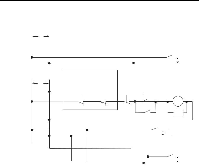
A hard-wired master control relay (MCR) provides a reliable means for emergency machine shutdown. Since the master control relay allows the placement of several emergency-stop switches in different locations, its installation is important from a safety standpoint. Overtravel limit switches or mushroom-head push buttons are wired in series so that when any of them opens, the master control relay is de-energized. This removes power to input and output device circuits. Refer to the figures on pages 17 and 18.
14 |
Rockwell Automation Publication 2080-UM005A-EN-E - December 2013 |

About Your Controller |
Chapter 2 |
|
|
WARNING: Never alter these circuits to defeat their function since serious injury and/or machine damage could result.
TIP |
If you are using an external DC power supply, interrupt the DC output |
|
side rather than the AC line side of the supply to avoid the additional |
|
delay of power supply turn-off. |
|
The AC line of the DC output power supply should be fused. |
|
Connect a set of master control relays in series with the DC power |
|
supplying the input and output circuits. |
Place the main power disconnect switch where operators and maintenance personnel have quick and easy access to it. If you mount a disconnect switch inside the controller enclosure, place the switch operating handle on the outside of the enclosure, so that you can disconnect power without opening the enclosure.
Whenever any of the emergency-stop switches are opened, power to input and output devices should be removed.
When you use the master control relay to remove power from the external I/O circuits, power continues to be provided to the controller’s power supply so that diagnostic indicators on the processor can still be observed.
The master control relay is not a substitute for a disconnect to the controller. It is intended for any situation where the operator must quickly de-energize I/O devices only. When inspecting or installing terminal connections, replacing output fuses, or working on equipment within the enclosure, use the disconnect to shut off power to the rest of the system.
TIP |
Do not control the master control relay with the controller. Provide the |
|
operator with the safety of a direct connection between an emergency- |
|
stop switch and the master control relay. |
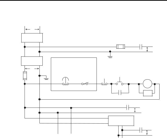
Using Emergency-Stop Switches
When using emergency-stop switches, adhere to the following points:
•Do not program emergency-stop switches in the controller program. Any emergency-stop switch should turn off all machine power by turning off the master control relay.
•Observe all applicable local codes concerning the placement and labeling of emergency-stop switches.
Rockwell Automation Publication 2080-UM005A-EN-E - December 2013 |
15 |

Chapter 2 About Your Controller
•Install emergency-stop switches and the master control relay in your system. Make certain that relay contacts have a sufficient rating for your application. Emergency-stop switches must be easy to reach.
•In the following illustration, input and output circuits are shown with MCR protection. However, in most applications, only output circuits require MCR protection.
The following illustrations show the Master Control Relay wired in a grounded system.
TIP |
In most applications input circuits do not require MCR protection; |
|
however, if you need to remove power from all field devices, you must |
|
include MCR contacts in series with input power wiring. |
16 |
Rockwell Automation Publication 2080-UM005A-EN-E - December 2013 |
About Your Controller Chapter 2
Schematic (Using IEC Symbols)
|
|
L1 |
L2 |
|
|
|
|
|
|
|
|
|
|
|
|
|
|
|
|
|
|
|
|
|
|
|
|
|
|
|
||||||
|
|
|
|
230V AC |
|
|
|
|
|
|
|
|
|
|
|
|
|
|
|
|
|
|
|
|
|
|
|
|
|
|
|
|
|
|
|
|
|
|
|
|
|
|
|
|
|
|
|
|
|
|
|
|
|
|
|
|
|
|
|
|
|
|
|
|
|
|
|
|
|
|
|
|
|
|
|
|
|
|
|
|
|
|
|
|
|
|
|
|
|
|
|
|
|
|
|
|
|
|
|
|
|
|
|
|
|
|
|
|
|
|
|
|
|
|
Disconnect |
|
|
|
|
|
|
|
|
|
|
|
|
|
|
|
|
|
|
|
|
|
|
|
|
|
|
|
|
|
|
|
|
|
|
|
|
|
|
|
|
|
|
|
|
|
|
|
|
|
|
|
|
|
|
|
|
|
|
|
|
|
|
Fuse |
MCR |
|||||
|
|
|
|
|
|
|
|
|
|
|
|
|
|
|
|
|
|
|
|
|
|
|
|
|
|
|
|
|
|
|
|
|
|
|
|
230V AC |
|
|
|
|
|
|
|
|
|
|
|
|
|
|
|
|
|
|
|
|
|
|
|
|
|
|
|
|
|
|
|
|
|
|
|
|
|
|
|
|
|
|
|
|
|
|
|
|
|
|
|
|
|
|
|
|
|
|
|
|
|
|
|
|
|
|
|
|
|
|
|
|
|
|
|
|
|
|
|
|
|
|
|
|
|
|
|
|
|
|
|
|
|
|
|
|
|
|
|
|
|
|
|
|
|
|
|
|
|
|
I/O |
|
|
|
|
|
|
|
|
|
|
|
|
|
|
|
|
|
|
|
|
|
|
|
|
|
|
|
|
|
|
|
|
|
|
|
|
|
|
|
|
|
|
|
|
|
|
|
|
|
|
|
|
|
|
|
|
|
|
|
|
|
|
|
|
|
|
|
|
|
|
|
|
|
Circuits |
|
|
|
|
|
|
|
|
|
|
|
|
|
|
|
|
|
|
|
|
|
|
|
|
|
|
|
|
|
|
|
|
|
|
|
|
|
|
|
|
|
|
|
|
|
|
|
|
|
|
|
|
|
|
|
|
|
|
|
|
|
|
|
|
|
|
|
|
|
|
|
|
|
|
|
|
|
Isolation |
|
|
|
|
|
|
|
|
Operation of either of these contacts will |
|
|
|
|
|
|
|
|
|
|
|
|
||||||||||||
|
|
|
Transformer |
|
|
|
|
|
|
|
|
remove power from the external I/O |
|
|
|
|
|
|
|
Master Control Relay (MCR) |
||||||||||||||||
|
|
|
|
|
|
|
|
|
|
|
|
|
circuits, stopping machine motion. |
|
|
|
|
|
|
|
||||||||||||||||
X1 |
|
115V AC |
X2 |
|
|
|
|
|
|
|
|
|
|
Cat. No. 700-PK400A1 |
||||||||||||||||||||||
|
|
or 230V AC |
|
|
|
Emergency-Stop |
|
|
|
|
|
|
|
|
|
|
|
|
|
|
|
Suppressor |
||||||||||||||
|
|
|
|
Fuse |
|
|
|
|
|
|
|
|
Push Button |
Stop |
|
|
Start |
Cat. No. 700-N24 |
||||||||||||||||||
|
|
|
|
|
|
|
|
|
|
|
|
|
|
|||||||||||||||||||||||
|
|
|
|
|
|
|
|
|
|
|
|
Overtravel |
|
|
|
|
|
|
|
|||||||||||||||||
|
|
|
|
|
|
|
|
|
|
|
|
|
|
|
|
|
|
Limit Switch |
|
|
|
|
|
|
|
|
|
|
|
|
|
|
|
|||
|
|
|
|
|
|
|
|
|
|
|
|
|
|
|
|
|
|
|
|
|
|
|
|
|
|
|
|
|
|
|
|
|
||||
|
MCR |
MCR |
Suppr. |
|
|
|
MCR |
115V AC or
230V AC I/O Circuits
|
|
|
DC Power Supply. |
|
|
|
|
|
||
|
|
|
|
|
|
|
|
|||
|
|
|
Use IEC 950/EN 60950 |
MCR |
||||||
|
|
|
|
|
|
|||||
|
|
_ |
|
+ |
|
|
|
|
24V DC |
|
(Lo) |
(Hi) |
|
|
|
|
|
|
|
||
|
|
|
|
|
|
|
|
|||
|
|
|
|
|
|
|
|
I/O |
||
Line Terminals: Connect to terminals of Power |
|
|
|
|
|
|
|
|
||
Line Terminals: |
|
|
|
|
|
|
Circuits |
|||
|
|
|
|
|
|
|||||
Supply |
|
Connect to 24V DC terminals of |
||||||||
|
|
Power Supply |
|
|
|
|
|
|
|
|
|
|
|
|
|
|
44564 |
||||
Rockwell Automation Publication 2080-UM005A-EN-E - December 2013 |
17 |
Chapter 2 About Your Controller
Schematic (Using ANSI/CSA Symbols)
L1 230V AC L2 |
|
|
|
|
|
|
|
|
|
Disconnect |
|
|
|
|
|
|
|
|
|
|
|
|
|
Fuse |
MCR |
230V AC |
|
|
|
|
|
|
|
|
|
|
|
|
|
|
|
|
|
Output |
|
|
|
|
|
|
|
|
Circuits |
Isolation |
|
Operation of either of these contacts will |
|
|
|
|
||
Transformer |
|
|
|
|
|
|||
|
remove power from the external I/O |
|
|
Master Control Relay (MCR) |
||||
|
|
|
|
|
||||
|
115V AC or |
|
circuits, stopping machine motion. |
|
|
|||
X1 |
X2 |
|
|
Cat. No. 700-PK400A1 |
||||
230V AC |
Emergency-Stop |
|
|
|
||||
|
|
|
|
|
Suppressor |
|
||
|
Fuse |
|
Push Button |
Overtravel |
Stop |
Start |
Cat. No. 700-N24 |
|
|
|
|
|
|
|
|||
|
|
|
|
Limit Switch |
|
|
|
|
|
|
|
|
|
|
|
MCR |
|
|
|
|
Suppr. |
|
|
MCR |
|
|
|
|
|
MCR |
115V AC or |
|
|
|
|
||
|
|
|
230V AC |
|
|
|
|
I/O Circuits |
|
|
DC Power Supply. Use |
|
||
|
NEC Class 2 for UL |
|
||
|
Listing. |
+ |
MCR |
|
(Lo) |
_ |
24 V DC |
||
(Hi) |
|
|||
Line Terminals: Connect to terminals of Power |
|
I/O |
||
|
Circuits |
|||
Supply |
|
|
||
Line Terminals: Connect to 24V DC terminals of |
||||
|
||||
|
Power Supply |
|
|
|
|
|
|
44565 |
|
18 |
Rockwell Automation Publication 2080-UM005A-EN-E - December 2013 |
Chapter 3
Install Your Controller
Controller Mounting
Dimensions
This chapter serves to guide the user on installing the controller. It includes the following topics.
Topic |
Page |
|
|
Controller Mounting Dimensions |
19 |
|
|
Connect the Controller to an EtherNet/IP Network |
21 |
|
|
Module Spacing |
20 |
|
|
DIN Rail Mounting |
20 |
|
|
Panel Mounting |
20 |
|
|
Panel Mounting Dimensions |
21 |
|
|
Install the microSD Card |
22 |
|
|
Install the 2080-REMLCD Module |
23 |
|
|
Mounting dimensions do not include mounting feet or DIN rail latches.
104 (4.09) |
75 (2.95) |
|
90 (3.54)
46205
Measurements in millimeters (inches)
Rockwell Automation Publication 2080-UM005A-EN-E - December 2013 |
19 |

Chapter 3 Install Your Controller
Module Spacing
Maintain spacing from enclosure walls, wireways, and adjacent equipment. Allow 50.8 mm (2 in.) of space on all sides. This provides ventilation and electrical isolation. If optional accessories/modules are attached to the controller, such as the power supply 2080-PS120-240VAC or expansion I/O modules, make sure that there is 50.8 mm (2 in.) of space on all sides after attaching the optional parts.
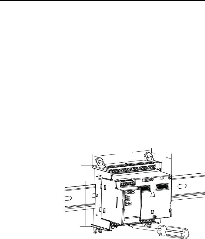
DIN Rail Mounting
The module can be mounted using the following DIN rails: 35 x 7.5 x 1 mm and 35 x 15 mm (EN 50 022 - 35 x 7.5 and EN 50 022 - 35 x 15).
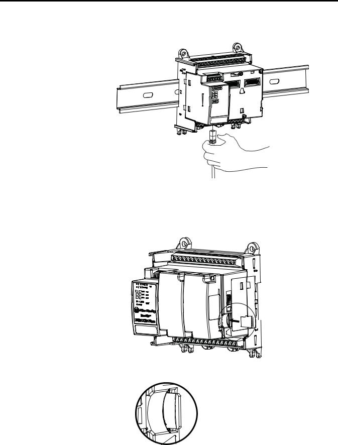
TIP For environments with greater vibration and shock concerns, use the panel mounting method, instead of DIN rail mounting.
Before mounting the module on a DIN rail, use a flat-blade screwdriver in the DIN rail latch and pry it downwards until it is in the unlatched position.
1.Hook the top of the DIN rail mounting area of the controller onto the DIN rail, and then press the bottom until the controller snaps onto the DIN rail.
2.Push the DIN rail latch back into the latched position.
Use DIN rail end anchors (Allen-Bradley part number 1492-EAJ35 or 1492-EAHJ35) for vibration or shock environments.
To remove your controller from the DIN rail, pry the DIN rail latch downwards until it is in the unlatched position.
Panel Mounting
The preferred mounting method is to use four M4 (#8) screws per module. Hole spacing tolerance: ±0.4 mm (0.016 in.).
Follow these steps to install your controller using mounting screws.
1.Place the controller against the panel where you are mounting it. Make sure the controller is spaced properly.
2.Mark drilling holes through the mounting screw holes and mounting feet then remove the controller.
3.Drill the holes at the markings, then replace the controller and mount it. Leave the protective debris strip in place until you are finished wiring the controller and any other devices.
20 |
Rockwell Automation Publication 2080-UM005A-EN-E - December 2013 |
Install Your Controller |
Chapter 3 |
|
|
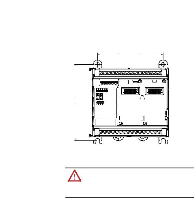
Panel Mounting Dimensions
Micro820 20-point controllers
2080-LC20-20AWB, 2080-LC20-20QWB, 2080-LC20-20QBB 2080-LC20-20AWBR, 2080-LC20-20QWBR, 2080-LC20-20QBBR
86 mm (3.39 in.)
100 mm
(3.94 in.)
46204
Connect the Controller to an EtherNet/IP Network
WARNING: If you connect or disconnect the communications cable with power applied to this module or any device on the network, an electrical arc can occur. This could cause an explosion in hazardous location installations.
Be sure that power is removed or the area is nonhazardous before proceeding.
Rockwell Automation Publication 2080-UM005A-EN-E - December 2013 |
21 |
Chapter 3 Install Your Controller
Connect the RJ-45 connector of the Ethernet cable to the Ethernet port on the controller. The port is on the bottom of the controller.
Install the microSD Card
46214
1.Insert the microSD card into the card slot.
You can install the microSD card in one orientation only. The beveled corner should be at the bottom. If you feel resistance when inserting the microSD card, pull it out and change the orientation.

 Insert the microSD
 card into the slot.
46218
2. Gently press the card until it clicks into place.
46219
22 |
Rockwell Automation Publication 2080-UM005A-EN-E - December 2013 |
Loading...