


 Loading...
User Manual
E300 Electronic Overload Relay
Bul. 193/592

Important User Information
Read this document and the documents listed in the additional resources section about installation, configuration, and operation of this equipment before you install, configure, operate, or maintain this product. Users are required to familiarize themselves with installation and wiring instructions in addition to requirements of all applicable codes, laws, and standards.
Activities including installation, adjustments, putting into service, use, assembly, disassembly, and maintenance are required to be carried out by suitably trained personnel in accordance with applicable code of practice.
If this equipment is used in a manner not specified by the manufacturer, the protection provided by the equipment may be impaired.
In no event will Rockwell Automation, Inc. be responsible or liable for indirect or consequential damages resulting from the use or application of this equipment.
The examples and diagrams in this manual are included solely for illustrative purposes. Because of the many variables and requirements associated with any particular installation, Rockwell Automation, Inc. cannot assume responsibility or liability for actual use based on the examples and diagrams.
No patent liability is assumed by Rockwell Automation, Inc. with respect to use of information, circuits, equipment, or software described in this manual.
Reproduction of the contents of this manual, in whole or in part, without written permission of Rockwell Automation, Inc., is prohibited.
Throughout this manual, when necessary, we use notes to make you aware of safety considerations.
WARNING: Identifies information about practices or circumstances that can cause an explosion in a hazardous environment, which may lead to personal injury or death, property damage, or economic loss.
ATTENTION: Identifies information about practices or circumstances that can lead to personal injury or death, property damage, or economic loss. Attentions help you identify a hazard, avoid a hazard, and recognize the consequence.
IMPORTANT Identifies information that is critical for successful application and understanding of the product.
Labels may also be on or inside the equipment to provide specific precautions.
SHOCK HAZARD: Labels may be on or inside the equipment, for example, a drive or motor, to alert people that dangerous voltage may be present.
BURN HAZARD: Labels may be on or inside the equipment, for example, a drive or motor, to alert people that surfaces may reach dangerous temperatures.
ARC FLASH HAZARD: Labels may be on or inside the equipment, for example, a motor control center, to alert people to potential Arc Flash. Arc Flash will cause severe injury or death. Wear proper Personal Protective Equipment (PPE). Follow ALL Regulatory requirements for safe work practices and for Personal Protective Equipment (PPE).
Allen-Bradley, Rockwell Software, and Rockwell Automation are trademarks of Rockwell Automation, Inc. Trademarks not belonging to Rockwell Automation are property of their respective companies.

|
Table of Contents |
|
|
Chapter 1 |
|
Product Overview |
Overview . . . . . . . . . . . . . . . . . . . . . . . . . . . . . . . . . . . . . . . . . . . . . . . . . . . . . . . . |
11 |
|
Modular Design . . . . . . . . . . . . . . . . . . . . . . . . . . . . . . . . . . . . . . . . . . . . . . |
11 |
|
Communication Options . . . . . . . . . . . . . . . . . . . . . . . . . . . . . . . . . . . . . |
11 |
|
Diagnostic Information . . . . . . . . . . . . . . . . . . . . . . . . . . . . . . . . . . . . . . . |
12 |
|
Simplified Wiring . . . . . . . . . . . . . . . . . . . . . . . . . . . . . . . . . . . . . . . . . . . . |
12 |
|
Catalog Number Explanation . . . . . . . . . . . . . . . . . . . . . . . . . . . . . . . . . . . . . |
13 |
|
Sensing Module . . . . . . . . . . . . . . . . . . . . . . . . . . . . . . . . . . . . . . . . . . . . . . |
13 |
|
Control Module. . . . . . . . . . . . . . . . . . . . . . . . . . . . . . . . . . . . . . . . . . . . . . |
13 |
|
Communication Module. . . . . . . . . . . . . . . . . . . . . . . . . . . . . . . . . . . . . . |
13 |
|
Digital Expansion Module . . . . . . . . . . . . . . . . . . . . . . . . . . . . . . . . . . . . |
14 |
|
Analog Expansion Module . . . . . . . . . . . . . . . . . . . . . . . . . . . . . . . . . . . . |
14 |
|
Operator Station . . . . . . . . . . . . . . . . . . . . . . . . . . . . . . . . . . . . . . . . . . . . . |
14 |
|
Power Supply . . . . . . . . . . . . . . . . . . . . . . . . . . . . . . . . . . . . . . . . . . . . . . . . |
14 |
|
Module Description . . . . . . . . . . . . . . . . . . . . . . . . . . . . . . . . . . . . . . . . . . . . . . |
15 |
|
Sensing Module . . . . . . . . . . . . . . . . . . . . . . . . . . . . . . . . . . . . . . . . . . . . . . |
15 |
|
Control Module. . . . . . . . . . . . . . . . . . . . . . . . . . . . . . . . . . . . . . . . . . . . . . |
16 |
|
Communication Module. . . . . . . . . . . . . . . . . . . . . . . . . . . . . . . . . . . . . . |
16 |
|
Optional Add-On Modules . . . . . . . . . . . . . . . . . . . . . . . . . . . . . . . . . . . . . . . |
17 |
|
Optional Expansion I/O . . . . . . . . . . . . . . . . . . . . . . . . . . . . . . . . . . . . . . |
17 |
|
Optional Operator Station . . . . . . . . . . . . . . . . . . . . . . . . . . . . . . . . . . . . |
18 |
|
Optional Expansion Bus Power Supply . . . . . . . . . . . . . . . . . . . . . . . . . |
18 |
|
Protection Features. . . . . . . . . . . . . . . . . . . . . . . . . . . . . . . . . . . . . . . . . . . . . . . |
19 |
|
Standard Current-Based Protection. . . . . . . . . . . . . . . . . . . . . . . . . . . . |
19 |
|
Ground Fault Current Based Protection. . . . . . . . . . . . . . . . . . . . . . . . |
19 |
|
Voltage and Power Based Protection . . . . . . . . . . . . . . . . . . . . . . . . . . . |
19 |
|
Applications: . . . . . . . . . . . . . . . . . . . . . . . . . . . . . . . . . . . . . . . . . . . . . . . . . . . . |
20 |
|
Chapter 2 |
|
Installation and Wiring |
Introduction . . . . . . . . . . . . . . . . . . . . . . . . . . . . . . . . . . . . . . . . . . . . . . . . . . . . |
21 |
|
Receiving . . . . . . . . . . . . . . . . . . . . . . . . . . . . . . . . . . . . . . . . . . . . . . . . . . . . . . . . |
21 |
|
Unpacking/Inspecting . . . . . . . . . . . . . . . . . . . . . . . . . . . . . . . . . . . . . . . . . . . |
21 |
|
Storing . . . . . . . . . . . . . . . . . . . . . . . . . . . . . . . . . . . . . . . . . . . . . . . . . . . . . . . . . |
21 |
|
General Precautions . . . . . . . . . . . . . . . . . . . . . . . . . . . . . . . . . . . . . . . . . . . . . |
22 |
|
Base Relay Assembly . . . . . . . . . . . . . . . . . . . . . . . . . . . . . . . . . . . . . . . . . . . . . |
22 |
|
Control Module to Sensing Module Assembly. . . . . . . . . . . . . . . . . . . . . . |
23 |
|
Communication Module to Control Module Assembly . . . . . . . . . . . . . |
24 |
|
Expansion Bus Peripherals . . . . . . . . . . . . . . . . . . . . . . . . . . . . . . . . . . . . . . . . |
25 |
|
Expansion Bus Digital & Analog I/O Modules and Power Supply |
|
|
Installation . . . . . . . . . . . . . . . . . . . . . . . . . . . . . . . . . . . . . . . . . . . . . . . . . . . . . . |
26 |
|
Expansion Bus Operator Station Installation . . . . . . . . . . . . . . . . . . . . . . . |
26 |
|
Expansion Bus Network Installation . . . . . . . . . . . . . . . . . . . . . . . . . . . . . . . |
26 |
|
Starter Assembly . . . . . . . . . . . . . . . . . . . . . . . . . . . . . . . . . . . . . . . . . . . . . . . . . |
28 |
|
Starter Dimensions. . . . . . . . . . . . . . . . . . . . . . . . . . . . . . . . . . . . . . . . . . . . . . . |
29 |
|
DIN Rail / Panel Mount Dimensions . . . . . . . . . . . . . . . . . . . . . . . . . . . . . . |
31 |
Rockwell Automation Publication 193-UM015B-EN-P - June 2014 |
3 |

Table of Contents |
|
Expansion Bus Peripherals Dimensions. . . . . . . . . . . . . . . . . . . . . . . . . . . . . |
32 |
Terminals. . . . . . . . . . . . . . . . . . . . . . . . . . . . . . . . . . . . . . . . . . . . . . . . . . . . . . . . |
34 |
Sensing Module . . . . . . . . . . . . . . . . . . . . . . . . . . . . . . . . . . . . . . . . . . . . . . |
34 |
Control Module . . . . . . . . . . . . . . . . . . . . . . . . . . . . . . . . . . . . . . . . . . . . . . |
35 |
Expansion Digital Module. . . . . . . . . . . . . . . . . . . . . . . . . . . . . . . . . . . . . |
37 |
Expansion Analog Module . . . . . . . . . . . . . . . . . . . . . . . . . . . . . . . . . . . . |
38 |
Expansion Power Supply . . . . . . . . . . . . . . . . . . . . . . . . . . . . . . . . . . . . . . |
40 |
Grounding. . . . . . . . . . . . . . . . . . . . . . . . . . . . . . . . . . . . . . . . . . . . . . . . . . . . . . . |
41 |
Short-Circuit Ratings . . . . . . . . . . . . . . . . . . . . . . . . . . . . . . . . . . . . . . . . . . . . |
41 |
Fuse Coordination . . . . . . . . . . . . . . . . . . . . . . . . . . . . . . . . . . . . . . . . . . . . . . . |
42 |
Typical Motor Connections . . . . . . . . . . . . . . . . . . . . . . . . . . . . . . . . . . . . . . |
43 |
External Line Current Transformer Application . . . . . . . . . . . . . . . . . . . . |
44 |
Control Circuits . . . . . . . . . . . . . . . . . . . . . . . . . . . . . . . . . . . . . . . . . . . . . . . . . |
48 |
Chapter 3 |
|
System Operation and Configuration Introduction . . . . . . . . . . . . . . . . . . . . . . . . . . . . . . . . . . . . . . . . . . . . . . . . . . . . |
51 |
Device Modes . . . . . . . . . . . . . . . . . . . . . . . . . . . . . . . . . . . . . . . . . . . . . . . . . . . . |
51 |
Administration Mode. . . . . . . . . . . . . . . . . . . . . . . . . . . . . . . . . . . . . . . . . |
51 |
Operation Mode. . . . . . . . . . . . . . . . . . . . . . . . . . . . . . . . . . . . . . . . . . . . . . |
52 |
Run Mode . . . . . . . . . . . . . . . . . . . . . . . . . . . . . . . . . . . . . . . . . . . . . . . . . . . |
52 |
Test Mode . . . . . . . . . . . . . . . . . . . . . . . . . . . . . . . . . . . . . . . . . . . . . . . . . . . |
53 |
Invalid Configuration Mode. . . . . . . . . . . . . . . . . . . . . . . . . . . . . . . . . . . |
53 |
Option Match . . . . . . . . . . . . . . . . . . . . . . . . . . . . . . . . . . . . . . . . . . . . . . . . . . . |
54 |
Enable Option Match Protection Trip (Parameter 186). . . . . . . . . . |
55 |
Enable Option Match Protection Warning (Parameter 192) . . . . . |
56 |
Control Module Type (Parameter 221). . . . . . . . . . . . . . . . . . . . . . . . . |
56 |
Sensing Module Type (Parameter 222) . . . . . . . . . . . . . . . . . . . . . . . . . |
57 |
Communication Module Type (Parameter 223). . . . . . . . . . . . . . . . . |
57 |
Operator Station Type (Parameter 224) . . . . . . . . . . . . . . . . . . . . . . . . |
58 |
Digital I/O Expansion Module 1 Type (Parameter 225) . . . . . . . . . |
58 |
Digital I/O Expansion Module 2 Type (Parameter 226) . . . . . . . . . |
59 |
Digital I/O Expansion Module 3 Type (Parameter 227) . . . . . . . . . |
59 |
Digital I/O Expansion Module 4 Type (Parameter 228) . . . . . . . . . |
60 |
Analog I/O Expansion Module 1 Type (Parameter 229) . . . . . . . . . |
60 |
Analog I/O Expansion Module 2 Type (Parameter 230) . . . . . . . . . |
61 |
Analog I/O Expansion Module 3 Type (Parameter 231) . . . . . . . . . |
61 |
Analog I/O Expansion Module 4 Type (Parameter 232) . . . . . . . . . |
62 |
Option Match Action (Parameter 233). . . . . . . . . . . . . . . . . . . . . . . . . |
62 |
Security Policy . . . . . . . . . . . . . . . . . . . . . . . . . . . . . . . . . . . . . . . . . . . . . . . . . . . |
63 |
Device Configuration Policy. . . . . . . . . . . . . . . . . . . . . . . . . . . . . . . . . . . |
63 |
Device Reset Policy . . . . . . . . . . . . . . . . . . . . . . . . . . . . . . . . . . . . . . . . . . . |
63 |
Firmware Update Policy. . . . . . . . . . . . . . . . . . . . . . . . . . . . . . . . . . . . . . . |
64 |
Security Configuration Policy. . . . . . . . . . . . . . . . . . . . . . . . . . . . . . . . . . |
64 |
I/O Assignments . . . . . . . . . . . . . . . . . . . . . . . . . . . . . . . . . . . . . . . . . . . . . . . . . |
64 |
Input Pt00 Assignment (Parameter 196). . . . . . . . . . . . . . . . . . . . . . . . |
64 |
Input Pt01 Assignment (Parameter 197). . . . . . . . . . . . . . . . . . . . . . . . |
65 |
Input Pt02 Assignment (Parameter 198). . . . . . . . . . . . . . . . . . . . . . . . |
65 |
4 |
Rockwell Automation Publication 193-UM015B-EN-P - June 2014 |

Table of Contents
Operating Modes
Protective Trip and Warning
Functions
Input Pt03 Assignment (Parameter 199) . . . . . . . . . . . . . . . . . . . . . . . 66 Input Pt04 Assignment (Parameter 200) . . . . . . . . . . . . . . . . . . . . . . . 66
Input Pt05 Assignment (Parameter 201) . . . . . . . . . . . . . . . . . . . . . . . 67
Output Pt00 Assignment (Parameter 202) . . . . . . . . . . . . . . . . . . . . . 68 Output Pt01 Assignment (Parameter 203) . . . . . . . . . . . . . . . . . . . . . 68
Output Pt02 Assignment (Parameter 204) . . . . . . . . . . . . . . . . . . . . . 69
Activate FLA2 with Output Relay (Parameter 209) . . . . . . . . . . . . . 69
Expansion Bus Fault. . . . . . . . . . . . . . . . . . . . . . . . . . . . . . . . . . . . . . . . . . . . . . 69 Expansion Bus Trip. . . . . . . . . . . . . . . . . . . . . . . . . . . . . . . . . . . . . . . . . . . 70
Expansion Bus Warning . . . . . . . . . . . . . . . . . . . . . . . . . . . . . . . . . . . . . . 71
Emergency Start . . . . . . . . . . . . . . . . . . . . . . . . . . . . . . . . . . . . . . . . . . . . . . . . . 71 Introduction to Operating Modes . . . . . . . . . . . . . . . . . . . . . . . . . . . . . . . . . 73
Chapter 4
Introduction . . . . . . . . . . . . . . . . . . . . . . . . . . . . . . . . . . . . . . . . . . . . . . . . . . . . 75
Overload (Network) . . . . . . . . . . . . . . . . . . . . . . . . . . . . . . . . . . . . . . . . . . . . . 75
Monitor (Custom) . . . . . . . . . . . . . . . . . . . . . . . . . . . . . . . . . . . . . . . . . . . . . . . 76
Chapter 5
Introduction . . . . . . . . . . . . . . . . . . . . . . . . . . . . . . . . . . . . . . . . . . . . . . . . . . . . 77
Current Based Protection. . . . . . . . . . . . . . . . . . . . . . . . . . . . . . . . . . . . . . . . . 77
Overload Protection . . . . . . . . . . . . . . . . . . . . . . . . . . . . . . . . . . . . . . . . . . 80
Phase Loss Protection. . . . . . . . . . . . . . . . . . . . . . . . . . . . . . . . . . . . . . . . . 87
Ground Fault Current Protection . . . . . . . . . . . . . . . . . . . . . . . . . . . . . 89
Stall Protection. . . . . . . . . . . . . . . . . . . . . . . . . . . . . . . . . . . . . . . . . . . . . . . 96
Jam Protection . . . . . . . . . . . . . . . . . . . . . . . . . . . . . . . . . . . . . . . . . . . . . . . 98
Underload Protection . . . . . . . . . . . . . . . . . . . . . . . . . . . . . . . . . . . . . . . 101
Current Imbalance Protection. . . . . . . . . . . . . . . . . . . . . . . . . . . . . . . . 104
Line Under Current Protection . . . . . . . . . . . . . . . . . . . . . . . . . . . . . . 108
Line Over Current Protection . . . . . . . . . . . . . . . . . . . . . . . . . . . . . . . . 117
Line Loss Protection. . . . . . . . . . . . . . . . . . . . . . . . . . . . . . . . . . . . . . . . . 125
Voltage Based Protection . . . . . . . . . . . . . . . . . . . . . . . . . . . . . . . . . . . . . . . . 132
Under Voltage Protection. . . . . . . . . . . . . . . . . . . . . . . . . . . . . . . . . . . . 135
Over Voltage Protection . . . . . . . . . . . . . . . . . . . . . . . . . . . . . . . . . . . . . 138
Voltage Imbalance Protection . . . . . . . . . . . . . . . . . . . . . . . . . . . . . . . . 141
Phase Rotation Protection . . . . . . . . . . . . . . . . . . . . . . . . . . . . . . . . . . . 144
Frequency Protection . . . . . . . . . . . . . . . . . . . . . . . . . . . . . . . . . . . . . . . . 146
Power Based Protection . . . . . . . . . . . . . . . . . . . . . . . . . . . . . . . . . . . . . . . . . 152
Real Power (kW) Protection . . . . . . . . . . . . . . . . . . . . . . . . . . . . . . . . . 155
Reactive Power (kVAR) Protection . . . . . . . . . . . . . . . . . . . . . . . . . . . 162
Apparent Power (kVA) Protection. . . . . . . . . . . . . . . . . . . . . . . . . . . . 175
Power Factor Protection . . . . . . . . . . . . . . . . . . . . . . . . . . . . . . . . . . . . . 181
Control-Based Protection. . . . . . . . . . . . . . . . . . . . . . . . . . . . . . . . . . . . . . . . 194
Test Trip . . . . . . . . . . . . . . . . . . . . . . . . . . . . . . . . . . . . . . . . . . . . . . . . . . . 196
Operator Station Trip . . . . . . . . . . . . . . . . . . . . . . . . . . . . . . . . . . . . . . . 197
Remote Trip . . . . . . . . . . . . . . . . . . . . . . . . . . . . . . . . . . . . . . . . . . . . . . . . 198
Rockwell Automation Publication 193-UM015B-EN-P - June 2014 |
5 |

Table of Contents |
|
|
|
Start Inhibit Protection . . . . . . . . . . . . . . . . . . . . . . . . . . . . . . . . . . . . . . |
199 |
|
Preventive Maintenance. . . . . . . . . . . . . . . . . . . . . . . . . . . . . . . . . . . . . . |
202 |
|
Hardware Fault. . . . . . . . . . . . . . . . . . . . . . . . . . . . . . . . . . . . . . . . . . . . . . |
204 |
|
Configuration Trip . . . . . . . . . . . . . . . . . . . . . . . . . . . . . . . . . . . . . . . . . . |
205 |
|
Option Match. . . . . . . . . . . . . . . . . . . . . . . . . . . . . . . . . . . . . . . . . . . . . . . |
205 |
|
Expansion Bus Fault . . . . . . . . . . . . . . . . . . . . . . . . . . . . . . . . . . . . . . . . . |
205 |
|
Non-Volatile Storage Fault . . . . . . . . . . . . . . . . . . . . . . . . . . . . . . . . . . . |
205 |
|
Test Mode Trip . . . . . . . . . . . . . . . . . . . . . . . . . . . . . . . . . . . . . . . . . . . . . |
206 |
|
Chapter 6 |
|
Commands |
Introduction . . . . . . . . . . . . . . . . . . . . . . . . . . . . . . . . . . . . . . . . . . . . . . . . . . . |
209 |
|
Trip Reset . . . . . . . . . . . . . . . . . . . . . . . . . . . . . . . . . . . . . . . . . . . . . . . . . . . . . . |
209 |
|
Configuration Preset . . . . . . . . . . . . . . . . . . . . . . . . . . . . . . . . . . . . . . . . . . . . |
209 |
|
Factory Defaults . . . . . . . . . . . . . . . . . . . . . . . . . . . . . . . . . . . . . . . . . . . . . |
210 |
|
Clear Command . . . . . . . . . . . . . . . . . . . . . . . . . . . . . . . . . . . . . . . . . . . . . . . . |
213 |
|
Clear Operating Statistics . . . . . . . . . . . . . . . . . . . . . . . . . . . . . . . . . . . . |
214 |
|
Clear History Logs. . . . . . . . . . . . . . . . . . . . . . . . . . . . . . . . . . . . . . . . . . . |
214 |
|
Clear %TCU. . . . . . . . . . . . . . . . . . . . . . . . . . . . . . . . . . . . . . . . . . . . . . . . |
215 |
|
Clear kWh . . . . . . . . . . . . . . . . . . . . . . . . . . . . . . . . . . . . . . . . . . . . . . . . . . |
215 |
|
Clear kVARh. . . . . . . . . . . . . . . . . . . . . . . . . . . . . . . . . . . . . . . . . . . . . . . . |
215 |
|
Clear kVAh . . . . . . . . . . . . . . . . . . . . . . . . . . . . . . . . . . . . . . . . . . . . . . . . . |
216 |
|
Clear Max kW Demand. . . . . . . . . . . . . . . . . . . . . . . . . . . . . . . . . . . . . . |
216 |
|
Clear Max kVAR Demand . . . . . . . . . . . . . . . . . . . . . . . . . . . . . . . . . . . |
216 |
|
Clear Max kVA Demand . . . . . . . . . . . . . . . . . . . . . . . . . . . . . . . . . . . . . |
216 |
|
Clear All . . . . . . . . . . . . . . . . . . . . . . . . . . . . . . . . . . . . . . . . . . . . . . . . . . . . |
216 |
|
Chapter 7 |
|
Metering and Diagnostics |
Introduction . . . . . . . . . . . . . . . . . . . . . . . . . . . . . . . . . . . . . . . . . . . . . . . . . . . . |
219 |
|
Device Monitor . . . . . . . . . . . . . . . . . . . . . . . . . . . . . . . . . . . . . . . . . . . . . . . . . |
219 |
|
Percent Thermal Capacity Utilized. . . . . . . . . . . . . . . . . . . . . . . . . . . . |
219 |
|
Time to Trip . . . . . . . . . . . . . . . . . . . . . . . . . . . . . . . . . . . . . . . . . . . . . . . . |
220 |
|
Time To Reset . . . . . . . . . . . . . . . . . . . . . . . . . . . . . . . . . . . . . . . . . . . . . . |
220 |
|
Current Trip Status. . . . . . . . . . . . . . . . . . . . . . . . . . . . . . . . . . . . . . . . . . |
221 |
|
Voltage Trip Status . . . . . . . . . . . . . . . . . . . . . . . . . . . . . . . . . . . . . . . . . . |
222 |
|
Power Trip Status . . . . . . . . . . . . . . . . . . . . . . . . . . . . . . . . . . . . . . . . . . . |
223 |
|
Control Trip Status. . . . . . . . . . . . . . . . . . . . . . . . . . . . . . . . . . . . . . . . . . |
223 |
|
Current Warning Status . . . . . . . . . . . . . . . . . . . . . . . . . . . . . . . . . . . . . |
224 |
|
Voltage Warning Status . . . . . . . . . . . . . . . . . . . . . . . . . . . . . . . . . . . . . . |
225 |
|
Power Warning Status . . . . . . . . . . . . . . . . . . . . . . . . . . . . . . . . . . . . . . . |
226 |
|
Control Warning Status. . . . . . . . . . . . . . . . . . . . . . . . . . . . . . . . . . . . . . |
226 |
|
Input Status 0 . . . . . . . . . . . . . . . . . . . . . . . . . . . . . . . . . . . . . . . . . . . . . . . |
227 |
|
Input Status 1 . . . . . . . . . . . . . . . . . . . . . . . . . . . . . . . . . . . . . . . . . . . . . . . |
227 |
|
Output Status . . . . . . . . . . . . . . . . . . . . . . . . . . . . . . . . . . . . . . . . . . . . . . . |
228 |
|
Operator Station Status . . . . . . . . . . . . . . . . . . . . . . . . . . . . . . . . . . . . . . |
229 |
|
Device Status 0 . . . . . . . . . . . . . . . . . . . . . . . . . . . . . . . . . . . . . . . . . . . . . . |
230 |
|
Device Status 1 . . . . . . . . . . . . . . . . . . . . . . . . . . . . . . . . . . . . . . . . . . . . . . |
231 |
6 |
Rockwell Automation Publication 193-UM015B-EN-P - June 2014 |

Table of Contents
Firmware Revision Number . . . . . . . . . . . . . . . . . . . . . . . . . . . . . . . . . . 231 Control Module ID . . . . . . . . . . . . . . . . . . . . . . . . . . . . . . . . . . . . . . . . . 232
Sensing Module ID . . . . . . . . . . . . . . . . . . . . . . . . . . . . . . . . . . . . . . . . . . 232
Operator Station ID . . . . . . . . . . . . . . . . . . . . . . . . . . . . . . . . . . . . . . . . . 233 Expansion Digital Module ID . . . . . . . . . . . . . . . . . . . . . . . . . . . . . . . . 233
Operating Time . . . . . . . . . . . . . . . . . . . . . . . . . . . . . . . . . . . . . . . . . . . . . 234
Starts Counter . . . . . . . . . . . . . . . . . . . . . . . . . . . . . . . . . . . . . . . . . . . . . . 234
Starts Available. . . . . . . . . . . . . . . . . . . . . . . . . . . . . . . . . . . . . . . . . . . . . . 234 Time to Start. . . . . . . . . . . . . . . . . . . . . . . . . . . . . . . . . . . . . . . . . . . . . . . . 235
Year . . . . . . . . . . . . . . . . . . . . . . . . . . . . . . . . . . . . . . . . . . . . . . . . . . . . . . . . 235
Month . . . . . . . . . . . . . . . . . . . . . . . . . . . . . . . . . . . . . . . . . . . . . . . . . . . . . 235 Day . . . . . . . . . . . . . . . . . . . . . . . . . . . . . . . . . . . . . . . . . . . . . . . . . . . . . . . . 236
Hour . . . . . . . . . . . . . . . . . . . . . . . . . . . . . . . . . . . . . . . . . . . . . . . . . . . . . . . 236
Minute . . . . . . . . . . . . . . . . . . . . . . . . . . . . . . . . . . . . . . . . . . . . . . . . . . . . . 236 Second . . . . . . . . . . . . . . . . . . . . . . . . . . . . . . . . . . . . . . . . . . . . . . . . . . . . . 237
Invalid Configuration Parameter . . . . . . . . . . . . . . . . . . . . . . . . . . . . . 237
Invalid Configuration Cause . . . . . . . . . . . . . . . . . . . . . . . . . . . . . . . . . 237 Mismatch Status . . . . . . . . . . . . . . . . . . . . . . . . . . . . . . . . . . . . . . . . . . . . 238
Current Monitor. . . . . . . . . . . . . . . . . . . . . . . . . . . . . . . . . . . . . . . . . . . . . . . . 238
L1 Current . . . . . . . . . . . . . . . . . . . . . . . . . . . . . . . . . . . . . . . . . . . . . . . . . 238 L2 Current . . . . . . . . . . . . . . . . . . . . . . . . . . . . . . . . . . . . . . . . . . . . . . . . . 239
L3 Current . . . . . . . . . . . . . . . . . . . . . . . . . . . . . . . . . . . . . . . . . . . . . . . . . 239
Average Current . . . . . . . . . . . . . . . . . . . . . . . . . . . . . . . . . . . . . . . . . . . . 239 L1 Percent FLA . . . . . . . . . . . . . . . . . . . . . . . . . . . . . . . . . . . . . . . . . . . . . 240
L2 Percent FLA . . . . . . . . . . . . . . . . . . . . . . . . . . . . . . . . . . . . . . . . . . . . . 240
L3 Percent FLA . . . . . . . . . . . . . . . . . . . . . . . . . . . . . . . . . . . . . . . . . . . . . 241 Average Percent FLA . . . . . . . . . . . . . . . . . . . . . . . . . . . . . . . . . . . . . . . . 241
Ground Fault Current . . . . . . . . . . . . . . . . . . . . . . . . . . . . . . . . . . . . . . . 241
Current Imbalance . . . . . . . . . . . . . . . . . . . . . . . . . . . . . . . . . . . . . . . . . . 242 Voltage Monitor . . . . . . . . . . . . . . . . . . . . . . . . . . . . . . . . . . . . . . . . . . . . . . . . 242
L1-L2 Voltage. . . . . . . . . . . . . . . . . . . . . . . . . . . . . . . . . . . . . . . . . . . . . . . 242
L2-L3 Voltage. . . . . . . . . . . . . . . . . . . . . . . . . . . . . . . . . . . . . . . . . . . . . . . 243 Average L-L Voltage . . . . . . . . . . . . . . . . . . . . . . . . . . . . . . . . . . . . . . . . . 243
L1-N Voltage . . . . . . . . . . . . . . . . . . . . . . . . . . . . . . . . . . . . . . . . . . . . . . . 244 L2-N Voltage . . . . . . . . . . . . . . . . . . . . . . . . . . . . . . . . . . . . . . . . . . . . . . . 244 L3-N Voltage . . . . . . . . . . . . . . . . . . . . . . . . . . . . . . . . . . . . . . . . . . . . . . . 244 Average L-N Voltage . . . . . . . . . . . . . . . . . . . . . . . . . . . . . . . . . . . . . . . . 245
Voltage Imbalance . . . . . . . . . . . . . . . . . . . . . . . . . . . . . . . . . . . . . . . . . . . 245 Frequency . . . . . . . . . . . . . . . . . . . . . . . . . . . . . . . . . . . . . . . . . . . . . . . . . . 246
Phase Rotation . . . . . . . . . . . . . . . . . . . . . . . . . . . . . . . . . . . . . . . . . . . . . . 246
Power Monitor . . . . . . . . . . . . . . . . . . . . . . . . . . . . . . . . . . . . . . . . . . . . . . . . . 246 Power Scale . . . . . . . . . . . . . . . . . . . . . . . . . . . . . . . . . . . . . . . . . . . . . . . . . 247
L1 Real Power. . . . . . . . . . . . . . . . . . . . . . . . . . . . . . . . . . . . . . . . . . . . . . . 247 L2 Real Power. . . . . . . . . . . . . . . . . . . . . . . . . . . . . . . . . . . . . . . . . . . . . . . 247 L3 Real Power. . . . . . . . . . . . . . . . . . . . . . . . . . . . . . . . . . . . . . . . . . . . . . . 248
Total Real Power . . . . . . . . . . . . . . . . . . . . . . . . . . . . . . . . . . . . . . . . . . . . 248
L1 Reactive Power. . . . . . . . . . . . . . . . . . . . . . . . . . . . . . . . . . . . . . . . . . . 249
Rockwell Automation Publication 193-UM015B-EN-P - June 2014 |
7 |

Table of Contents
L2 Reactive Power . . . . . . . . . . . . . . . . . . . . . . . . . . . . . . . . . . . . . . . . . . . 249 L3 Reactive Power . . . . . . . . . . . . . . . . . . . . . . . . . . . . . . . . . . . . . . . . . . . 250
Total Reactive Power . . . . . . . . . . . . . . . . . . . . . . . . . . . . . . . . . . . . . . . . 250
L1 Apparent Power . . . . . . . . . . . . . . . . . . . . . . . . . . . . . . . . . . . . . . . . . . 250 L2 Apparent Power . . . . . . . . . . . . . . . . . . . . . . . . . . . . . . . . . . . . . . . . . . 251
L3 Apparent Power . . . . . . . . . . . . . . . . . . . . . . . . . . . . . . . . . . . . . . . . . . 251
Total Apparent Power . . . . . . . . . . . . . . . . . . . . . . . . . . . . . . . . . . . . . . . 252
L1 Power Factor . . . . . . . . . . . . . . . . . . . . . . . . . . . . . . . . . . . . . . . . . . . . . 252 L2 Power Factor Power . . . . . . . . . . . . . . . . . . . . . . . . . . . . . . . . . . . . . . 252
L3 Power Factor . . . . . . . . . . . . . . . . . . . . . . . . . . . . . . . . . . . . . . . . . . . . . 253
Total Power Factor . . . . . . . . . . . . . . . . . . . . . . . . . . . . . . . . . . . . . . . . . . 253 Energy Monitor . . . . . . . . . . . . . . . . . . . . . . . . . . . . . . . . . . . . . . . . . . . . . . . . . 254 kWh 109 . . . . . . . . . . . . . . . . . . . . . . . . . . . . . . . . . . . . . . . . . . . . . . . . . . . 254 kWh 106 . . . . . . . . . . . . . . . . . . . . . . . . . . . . . . . . . . . . . . . . . . . . . . . . . . . 254 kWh 103 . . . . . . . . . . . . . . . . . . . . . . . . . . . . . . . . . . . . . . . . . . . . . . . . . . . 255 kWh 100 . . . . . . . . . . . . . . . . . . . . . . . . . . . . . . . . . . . . . . . . . . . . . . . . . . . 255 kWh 10-3. . . . . . . . . . . . . . . . . . . . . . . . . . . . . . . . . . . . . . . . . . . . . . . . . . . 255 kVARh Consumed 109 . . . . . . . . . . . . . . . . . . . . . . . . . . . . . . . . . . . . . . 256 kVARh Consumed 106 . . . . . . . . . . . . . . . . . . . . . . . . . . . . . . . . . . . . . . 256 kVARh Consumed 103 . . . . . . . . . . . . . . . . . . . . . . . . . . . . . . . . . . . . . . 257 kVARh Consumed 100 . . . . . . . . . . . . . . . . . . . . . . . . . . . . . . . . . . . . . . 257 kVARh Consumed 10-3 . . . . . . . . . . . . . . . . . . . . . . . . . . . . . . . . . . . . . 257 kVARh Generated 109. . . . . . . . . . . . . . . . . . . . . . . . . . . . . . . . . . . . . . . 258 kVARh Generated 106. . . . . . . . . . . . . . . . . . . . . . . . . . . . . . . . . . . . . . . 258 kVARh Generated 103. . . . . . . . . . . . . . . . . . . . . . . . . . . . . . . . . . . . . . . 259 kVARh Generated 100. . . . . . . . . . . . . . . . . . . . . . . . . . . . . . . . . . . . . . . 259 kVARh Generated 10-3 . . . . . . . . . . . . . . . . . . . . . . . . . . . . . . . . . . . . . . 259 kVARh Net 109 . . . . . . . . . . . . . . . . . . . . . . . . . . . . . . . . . . . . . . . . . . . . . 260 kVARh Net 106 . . . . . . . . . . . . . . . . . . . . . . . . . . . . . . . . . . . . . . . . . . . . . 260 kVARh Net 103 . . . . . . . . . . . . . . . . . . . . . . . . . . . . . . . . . . . . . . . . . . . . . 261 kVARh Net 100 . . . . . . . . . . . . . . . . . . . . . . . . . . . . . . . . . . . . . . . . . . . . . 261 kVARh Net 10-3 . . . . . . . . . . . . . . . . . . . . . . . . . . . . . . . . . . . . . . . . . . . . 261 kVAh 109. . . . . . . . . . . . . . . . . . . . . . . . . . . . . . . . . . . . . . . . . . . . . . . . . . . 262 kVAh 106. . . . . . . . . . . . . . . . . . . . . . . . . . . . . . . . . . . . . . . . . . . . . . . . . . . 262 kVAh 103. . . . . . . . . . . . . . . . . . . . . . . . . . . . . . . . . . . . . . . . . . . . . . . . . . . 263 kVAh 100. . . . . . . . . . . . . . . . . . . . . . . . . . . . . . . . . . . . . . . . . . . . . . . . . . . 263 kVAh 10-3 . . . . . . . . . . . . . . . . . . . . . . . . . . . . . . . . . . . . . . . . . . . . . . . . . . 263 kW Demand . . . . . . . . . . . . . . . . . . . . . . . . . . . . . . . . . . . . . . . . . . . . . . . . 264 Max kW Demand . . . . . . . . . . . . . . . . . . . . . . . . . . . . . . . . . . . . . . . . . . . 264 kVAR Demand. . . . . . . . . . . . . . . . . . . . . . . . . . . . . . . . . . . . . . . . . . . . . . 264
Max kVAR Demand . . . . . . . . . . . . . . . . . . . . . . . . . . . . . . . . . . . . . . . . . 265 kVA Demand . . . . . . . . . . . . . . . . . . . . . . . . . . . . . . . . . . . . . . . . . . . . . . . 265
Max kVA Demand. . . . . . . . . . . . . . . . . . . . . . . . . . . . . . . . . . . . . . . . . . . 265 Trip / Warning History. . . . . . . . . . . . . . . . . . . . . . . . . . . . . . . . . . . . . . . . . . 266 Trip History . . . . . . . . . . . . . . . . . . . . . . . . . . . . . . . . . . . . . . . . . . . . . . . . 266
Warning History . . . . . . . . . . . . . . . . . . . . . . . . . . . . . . . . . . . . . . . . . . . . 271
Trip Snapshot. . . . . . . . . . . . . . . . . . . . . . . . . . . . . . . . . . . . . . . . . . . . . . . . . . . 275
8 |
Rockwell Automation Publication 193-UM015B-EN-P - June 2014 |

|
Table of Contents |
|
|
Trip Snapshot L1-L2 Voltage. . . . . . . . . . . . . . . . . . . . . . . . . . . . . . . . . |
275 |
|
Trip Snapshot L2-L3 Voltage. . . . . . . . . . . . . . . . . . . . . . . . . . . . . . . . . |
276 |
|
Trip Snapshot L3-L1 Voltage. . . . . . . . . . . . . . . . . . . . . . . . . . . . . . . . . |
276 |
|
Trip Snapshot Total Real Power . . . . . . . . . . . . . . . . . . . . . . . . . . . . . . |
276 |
|
Trip Snapshot Total Reactive Power . . . . . . . . . . . . . . . . . . . . . . . . . . |
277 |
|
Trip Snapshot Total Apparent Power . . . . . . . . . . . . . . . . . . . . . . . . . |
277 |
|
Trip Snapshot Total Power Factor . . . . . . . . . . . . . . . . . . . . . . . . . . . . |
277 |
|
Chapter 8 |
|
EtherNet/IP Communications |
Introduction. . . . . . . . . . . . . . . . . . . . . . . . . . . . . . . . . . . . . . . . . . . . . . . . . . . . |
279 |
|
Network Design . . . . . . . . . . . . . . . . . . . . . . . . . . . . . . . . . . . . . . . . . . . . . . . . |
279 |
|
Determining Network Parameters . . . . . . . . . . . . . . . . . . . . . . . . . . . . . . . . |
281 |
|
Setting the IP Network Address . . . . . . . . . . . . . . . . . . . . . . . . . . . . . . . . . . |
282 |
|
EtherNet/IP Node Address Selection Switches . . . . . . . . . . . . . . . . |
282 |
|
Assign Network Parameters via the BOOTP/ DHCP Utility . . . |
283 |
|
Assign Network Parameters Via a Web Browser & MAC Scanner |
|
|
Software . . . . . . . . . . . . . . . . . . . . . . . . . . . . . . . . . . . . . . . . . . . . . . . . . . . . |
285 |
|
Other Factors to Consider When Assigning Network Parameters 285 |
|
|
Web Server . . . . . . . . . . . . . . . . . . . . . . . . . . . . . . . . . . . . . . . . . . . . . . . . . . . . . |
286 |
|
Duplicate IP Address Detection . . . . . . . . . . . . . . . . . . . . . . . . . . . . . . . . . . |
287 |
|
DNS Addressing . . . . . . . . . . . . . . . . . . . . . . . . . . . . . . . . . . . . . . . . . . . . . . . . |
288 |
|
Electronic Data Sheet (EDS) File Installation. . . . . . . . . . . . . . . . . . . . . . |
288 |
|
Download the EDS File. . . . . . . . . . . . . . . . . . . . . . . . . . . . . . . . . . . . . . |
289 |
|
View & Configure Parameters. . . . . . . . . . . . . . . . . . . . . . . . . . . . . . . . . . . . |
292 |
|
Viewing Parameters. . . . . . . . . . . . . . . . . . . . . . . . . . . . . . . . . . . . . . . . . . |
292 |
|
Editing Parameters . . . . . . . . . . . . . . . . . . . . . . . . . . . . . . . . . . . . . . . . . . |
293 |
|
Automation Controller Communications. . . . . . . . . . . . . . . . . . . . . . . . . |
295 |
|
I/O Messaging . . . . . . . . . . . . . . . . . . . . . . . . . . . . . . . . . . . . . . . . . . . . . . . . . . |
295 |
|
Logix Configuration with Add-On Profile. . . . . . . . . . . . . . . . . . . . . |
296 |
|
Logix Configuration with a Generic Profile . . . . . . . . . . . . . . . . . . . . |
301 |
|
E-mail/Text . . . . . . . . . . . . . . . . . . . . . . . . . . . . . . . . . . . . . . . . . . . . . . . . . . . . |
306 |
|
E-mail Configuration . . . . . . . . . . . . . . . . . . . . . . . . . . . . . . . . . . . . . . . . |
307 |
|
Text Notifications. . . . . . . . . . . . . . . . . . . . . . . . . . . . . . . . . . . . . . . . . . . |
309 |
|
Limitations . . . . . . . . . . . . . . . . . . . . . . . . . . . . . . . . . . . . . . . . . . . . . . . . . |
309 |
|
Troubleshooting . . . . . . . . . . . . . . . . . . . . . . . . . . . . . . . . . . . . . . . . . . . . . . . . |
309 |
|
Chapter 9 |
|
Firmware Updates |
Introduction . . . . . . . . . . . . . . . . . . . . . . . . . . . . . . . . . . . . . . . . . . . . . . . . . . . |
311 |
|
Firmware Compatibility . . . . . . . . . . . . . . . . . . . . . . . . . . . . . . . . . . . . . . . . . |
311 |
|
Upgrading Firmware . . . . . . . . . . . . . . . . . . . . . . . . . . . . . . . . . . . . . . . . . . . . |
312 |
|
Chapter 10 |
|
Troubleshooting |
Introduction. . . . . . . . . . . . . . . . . . . . . . . . . . . . . . . . . . . . . . . . . . . . . . . . . . . . |
317 |
|
Advisory LEDs. . . . . . . . . . . . . . . . . . . . . . . . . . . . . . . . . . . . . . . . . . . . . . . . . . |
317 |
|
Power LED . . . . . . . . . . . . . . . . . . . . . . . . . . . . . . . . . . . . . . . . . . . . . . . . . |
317 |
|
Trip/Warn LED . . . . . . . . . . . . . . . . . . . . . . . . . . . . . . . . . . . . . . . . . . . . |
318 |
Rockwell Automation Publication 193-UM015B-EN-P - June 2014 |
9 |

Table of Contents |
|
|
|
Resetting a Trip . . . . . . . . . . . . . . . . . . . . . . . . . . . . . . . . . . . . . . . . . . . . . . . . . |
319 |
|
Trip/Warn LED Troubleshooting Procedures . . . . . . . . . . . . . . . . . . . . . |
320 |
|
Appendix A |
|
Specifications |
Electrical Specifications . . . . . . . . . . . . . . . . . . . . . . . . . . . . . . . . . . . . . . . . . . |
323 |
|
Low Voltage Directive . . . . . . . . . . . . . . . . . . . . . . . . . . . . . . . . . . . . . . . . . . . |
324 |
|
Environmental Specifications. . . . . . . . . . . . . . . . . . . . . . . . . . . . . . . . . . . . . |
325 |
|
Electromagnetic Compatibility Specifications. . . . . . . . . . . . . . . . . . . . . . |
326 |
|
Protection . . . . . . . . . . . . . . . . . . . . . . . . . . . . . . . . . . . . . . . . . . . . . . . . . . . . . . |
327 |
|
Accuracy. . . . . . . . . . . . . . . . . . . . . . . . . . . . . . . . . . . . . . . . . . . . . . . . . . . . . . . . |
328 |
|
Metering . . . . . . . . . . . . . . . . . . . . . . . . . . . . . . . . . . . . . . . . . . . . . . . . . . . . |
328 |
|
Protection Timers . . . . . . . . . . . . . . . . . . . . . . . . . . . . . . . . . . . . . . . . . . . |
328 |
|
Appendix B |
|
Parameter List |
Overview . . . . . . . . . . . . . . . . . . . . . . . . . . . . . . . . . . . . . . . . . . . . . . . . . . . . . . . |
331 |
|
Appendix C |
|
EtherNet/IP Information |
Common Industrial Protocol (CIP) Objects. . . . . . . . . . . . . . . . . . . . . . . |
371 |
|
Identity Object — CLASS CODE 0x0001 . . . . . . . . . . . . . . . . . . . . |
372 |
|
Message Router — CLASS CODE 0x0002 . . . . . . . . . . . . . . . . . . . . |
374 |
|
Assembly Object — CLASS CODE 0x0004 . . . . . . . . . . . . . . . . . . . |
374 |
|
Instance 2 . . . . . . . . . . . . . . . . . . . . . . . . . . . . . . . . . . . . . . . . . . . . . . . . . . . |
375 |
|
Instance 50. . . . . . . . . . . . . . . . . . . . . . . . . . . . . . . . . . . . . . . . . . . . . . . . . . |
376 |
|
Instance 120 - Configuration Assembly Revision 2 . . . . . . . . . . . . . |
376 |
|
Instance 120 - Configuration Assembly Revision 1 . . . . . . . . . . . . . |
386 |
|
Instance 144 – Default Consumed Assembly. . . . . . . . . . . . . . . . . . . |
386 |
|
Instance 198 - Current Diagnostics Produced Assembly. . . . . . . . . |
386 |
|
Instance 199 - All Diagnostics Produced Assembly . . . . . . . . . . . . . |
388 |
|
Connection Object — CLASS CODE 0x0005. . . . . . . . . . . . . . . . . |
390 |
|
Discrete Input Point Object — CLASS CODE 0x0008. . . . . . . . . |
393 |
|
Discrete Output Point Object — CLASS CODE 0x0009. . . . . . . |
394 |
|
Analog Input Point Object — CLASS CODE 0x000A . . . . . . . . . |
396 |
|
Analog Output Point Object — CLASS CODE 0x000B. . . . . . . . |
397 |
|
Parameter Object — CLASS CODE 0x000F . . . . . . . . . . . . . . . . . . |
398 |
|
Parameter Group Object — CLASS CODE 0x0010. . . . . . . . . . . . |
399 |
|
Discrete Output Group Object — CLASS CODE 0x001E . . . . . |
399 |
|
Control Supervisor Object — CLASS CODE 0x0029 . . . . . . . . . . |
400 |
|
Overload Object — CLASS CODE 0x002c . . . . . . . . . . . . . . . . . . . |
401 |
|
Base Energy Object — CLASS CODE 0x004E. . . . . . . . . . . . . . . . . |
401 |
|
Electrical Energy Object — CLASS CODE 0x004F . . . . . . . . . . . . |
403 |
|
Wall Clock Time Object — CLASS CODE 0x008B . . . . . . . . . . . |
405 |
|
DPI Fault Object — CLASS CODE 0x0097. . . . . . . . . . . . . . . . . . . |
406 |
|
DPI Warning Object — CLASS CODE 0x0098 . . . . . . . . . . . . . . . |
410 |
|
MCC Object — CLASS CODE 0x00C2. . . . . . . . . . . . . . . . . . . . . . |
413 |
|
Comm Adapter Info Object — CLASS CODE 0x0C8 . . . . . . . . . |
414 |
|
E300 Status Object — CLASS CODE 0x0375. . . . . . . . . . . . . . . . . |
414 |
10 |
Rockwell Automation Publication 193-UM015B-EN-P - June 2014 |
Chapter 1
Product Overview
Overview
The E300™ Electronic Overload Relay is a microprocessor-based electronic overload relay designed to protect three-phase or single-phase AC electric induction motors rated from 0.5…65,000 A. Its modular design, communication options, diagnostic information, simplified wiring, and integration into Logix makes this the ideal overload for motor control applications in an automation system. The E300 Electronic Overload Relay provides flexibility, reduces engineering time, and maximizes uptime for important motor starter applications.
Modular Design
Users can select the specific options needed for their motor starter application. The E300 Electronic Overload Relay consists of three modules: sensing, control and communications. Users have choices in each of the three with additional accessories to tailor the electronic motor overload for their application’s exact needs.
•Wide current range
•Sensing capabilities (Current, Ground Fault Current, and/or Voltage)
•Expansion I/O
•Operator interfaces
Communication Options
Users can select from multiple communication options which integrate with Logix based control systems. Developers can easily add the E300 Electronic Overload Relay to Logix based control systems using Integrated Architecture tools such as Add-on Profiles, Add-on Instructions, and Faceplates.
•EtherNet/IP (DLR)
•DeviceNet
Rockwell Automation Publication 193-UM015B-EN-P - June 2014 |
11 |

Chapter 1 Product Overview
Diagnostic Information
The E300 Electronic Overload Relay provides a wide variety of diagnostic information to monitor motor performance, proactively alert users to possible motor issues, or identify the reason for an unplanned shut down. Information includes:
•Voltage, Current, & Energy
•Trip / Warning Histories
•% Thermal Capacity Utilization
•Time to Trip
•Time to Reset
•Operational Hours
•Number of Starts
•Trip Snapshot
Simplified Wiring
The E300 Electronic Overload Relay provides an easy means to mount to both IEC and NEMA Allen-Bradley contactors. A contactor coil adapter is available for the 100-C contactor, which allows the user to create a functional motor starter with only two control wires.
12 |
Rockwell Automation Publication 193-UM015B-EN-P - June 2014 |

Product Overview |
Chapter 1 |
|
|
Catalog Number
Explanation
E300 Electronic Overload Relay modules have their own catalog number. The catalog numbers are explained below.
Sensing Module
|
|
|
|
|
|
193 - ESM - VIG - 30A - C23 |
|
|
|
|||||||
|
|
|
592 |
|
|
|
|
|
|
|
|
|
||||
|
|
|
|
|
|
|
|
|
|
|
|
|||||
|
|
|
|
|
|
|
|
|
|
|
|
|
|
|
|
|
|
|
|
|
|
|
|
|
|
|
|
|
|
|
|
||
|
|
Module |
|
Type |
|
|
|
|
|
|
|
|
|
|||
Bulletin |
Number |
|
Sensing Module Type |
Sensing Current Range |
||||||||||||
193 |
IEC Overload Relay |
ESM Sensing Module |
VIG |
Current, Ground Fault Current, |
30A |
0.5…30 A |
||||||||||
592 |
NEMA Overload Relay |
|
|
|
|
|
|
Voltage, & Power |
60A |
6…60 A |
||||||
|
|
|
|
|
|
|
|
IG |
Current & Ground Fault Current |
100A |
10…100 A |
|||||
|
|
|
|
|
|
|
|
I |
Current |
200A |
20…200 A |
|||||
|
|
|
|
|
|
|
|
|
|
|
|
|
|
|
|
|
|
|
|
|
|
|
|
|
|
|
|
|
|
|
|
|
|
Sensing Module Mounting Style
C23 Mounts to 100-C09…-C23 Contactor
C55 Mounts to 100-C30…-C55 Contactor
C97 Mounts to 100-C60…-C97 Contactor
D180 Mounts to 100-D115…-D180 Contactor
S2 Mounts to Bulletin 500 NEMA Size 0-2 Contactor
S3 Mounts to Bulletin 500 NEMA Size 3 Contactor
S4 Mounts to Bulletin 500 NEMA Size 4 Contactor
TDIN Rail / Panel Mount with Power Terminals
E3T Replacement DIN Rail / Panel Mount with Power Terminals for an E3 Plus Panel Mount Adapter
PDIN Rail / Panel Mount with Pass-thru Power Conductors
CT DIN Rail / Panel Mount with Pass-thru Power Conductors (used with External CTs)
Control Module
193 - EIO - 43 - 120
|
|
|
|
|
|
|
|
|
|
|
|
|
|
|
|
|
|
|
|
|
|
|
|
|
|
|
|
|
|
|
|
|
|
|
|
|
|
|
|
|
|
|
|
|
Bulletin |
Number |
Module |
|
Type |
I/O |
|
Count |
Control Voltage |
||||||
193 IEC Overload Relay |
EIO |
I/O Only Control Module |
63 |
6 Inputs / 3 Relay Outputs |
24D |
24V DC |
||||||||
|
|
EIOGP |
I/O and Protection Control Module |
43 |
4 Inputs / 3 Relay Outputs |
120 |
110…120V AC, 50/60 Hz |
|||||||
|
|
|
(External Ground Fault Sensing |
42 |
4 Inputs / 2 Relay Outputs |
240 |
220…240V AC, 50/60 H |
|||||||
|
|
|
and PTC) |
22 |
2 Inputs / 2 Relay Outputs |
|
|
|
||||||
Communication Module
193 - ECM - ETR
|
|
|
|
|
|
|
|
|
|
|
|
|
|
|
|
|
|
|
|
|
|
|
|
|
|
|
Bulletin |
Number |
Module Type |
|
Communication Type |
||||
193 IEC Overload Relay |
ECM Communication Module |
|
ETR |
EtherNet/IP with Dual Ethernet Ports |
||||
|
|
|
|
|
|
DNT |
DeviceNet |
|
Rockwell Automation Publication 193-UM015B-EN-P - June 2014 |
13 |

Chapter 1 Product Overview
Digital Expansion Module
193 - EXP - DIO - 42 - 120
|
|
|
|
|
|
|
|
|
|
|
|
|
|
|
|
|
|
|
|
|
|
|
|
|
|
|
|
|
|
|
|
|
|
|
|
|
|
|
|
|
|
|
|
|
|
|
|
|
|
|
|
|
|
|
|
|
|
|
|
|
|
|
|
|
|
|
|
Bulletin |
Number |
Module Type |
I/O Type |
|
|
I/O Count |
Communication Type |
|||||||||
193 IEC Overload Relay |
EXP Expansion Module |
DIO Digital I/O |
42 4 Inputs / 2 Relay Outputs |
120 |
110…120V AC, 50/60 Hz Inputs |
|||||||||||
|
|
|
|
|
|
|
|
|
|
|
|
|
|
240 |
220…240V AC, 50/60 Hz Inputs |
|
|
|
|
|
|
|
|
|
|
|
|
|
|
|
24D |
24V DC Inputs |
|
Analog Expansion Module
193 - EXP - AIO - 31
|
|
|
|
|
|
|
|
|
|
|
|
|
|
|
|
|
|
|
|
|
|
|
|
|
|
|
|
|
|
|
|
|
|
|
|
Bulletin |
Number |
Module Type |
I/O Type |
|
|
I/O Count |
|||||
193 IEC Overload Relay |
EXP Expansion Module |
AIO Analog I/O |
31 3 Universal Analog Inputs / 1 Analog Output |
||||||||
Operator Station
193 - EOS - SCS
|
|
|
|
|
|
|
|
|
|
|
|
|
|
|
|
|
|
|
|
Bulletin |
Number |
Module |
|
Type |
I/O Type |
||||
193 IEC Overload Relay |
EOS Operator Station |
SCS |
Starter Control Station |
||||||
|
|
|
|
|
|
|
SDS |
Starter Diagnostic Station |
|
Power Supply
193 - EXP - PS - AC
|
|
|
|
|
|
|
|
|
|
|
|
|
|
|
|
|
|
|
|
|
|
|
|
|
|
|
|
|
|
|
|
|
|
|
|
|
|
|
Bulletin |
Number |
Module Type |
Function |
|
Type |
Supply Voltage |
||||||
193 IEC Overload Relay |
EXP Expansion Module |
PS Expansion Bus Power Supply |
AC |
110-240V AC, 50/60Hz control voltage |
||||||||
|
|
|
|
|
|
|
|
|
|
|
DC |
24V DC control voltage |
14 |
Rockwell Automation Publication 193-UM015B-EN-P - June 2014 |
Product Overview |
Chapter 1 |
|
|
Module Description
The E300 Electronic Overload Relay is comprised of three modules. All three modules are required to make a functional overload relay.
•Sensing Module
•Control Module
•Communication Module
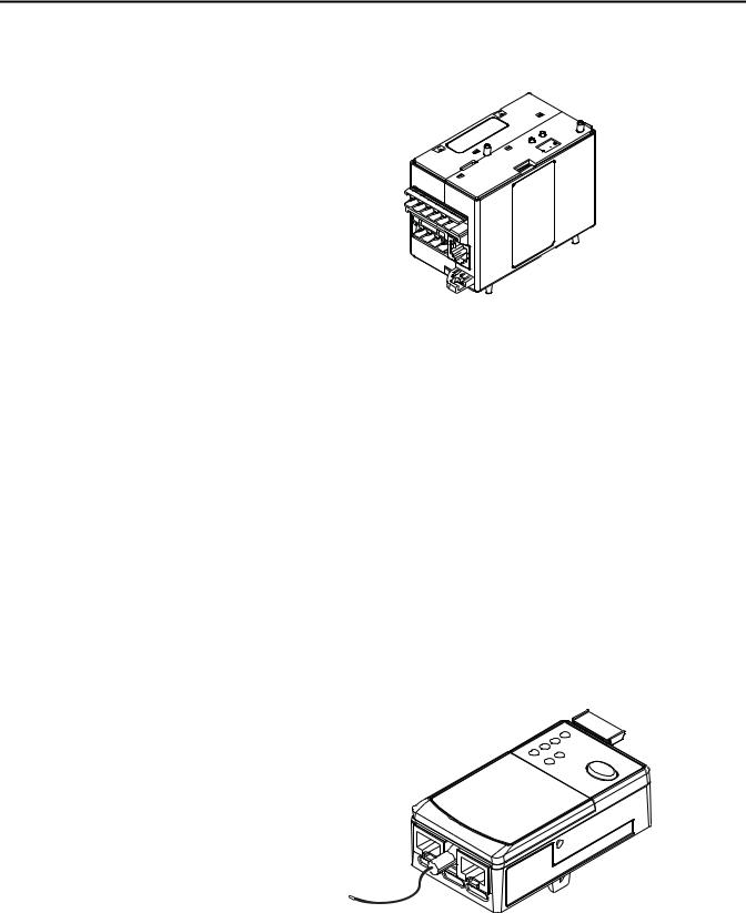
Sensing Module
Figure 1 - Sensing Module
The sensing module electronically samples the current, voltage, power, and energy data consumed by the electric motor internal to the module. Users can pick from one of three varieties of the sensing modules depending on the motor diagnostic information that is needed for the motor protection application:
•Current Sensing
•Current and Ground Fault Current Sensing
•Current, Ground Fault Current, Voltage, and Power Sensing
The current ranges for each of three varieties of sensing module are shown below:
•0.5…30 A
•6…60 A
•10…100 A
•20…200 A
Users can choose how the sensing module mechanically mounts inside the electrical enclosure. The following mounting mechanisms are available for the sensing module.
•Mount to the load side of an Allen-Bradley Bulletin 100 IEC Contactor
•Mount to the load side of an Allen-Bradley Bulletin 500 NEMA Contactor
•DIN Rail / Panel Mount with power terminals
•Replacement DIN Rail / Panel Mount with power terminals for an Allen-Bradley E3 Plus panel mount adapter
•DIN Rail / Panel Mount with pass-thru power conductors
Rockwell Automation Publication 193-UM015B-EN-P - June 2014 |
15 |
Chapter 1 Product Overview
Control Module
Figure 2 - Control Module
The control module is the heart of the E300 Electronic Overload Relay and can attach to any sensing module. The control module performs all of the protection and motor control algorithms and contains the native I/O for the system. The control module has two varieties:
•I/O only
•I/O and protection (PTC & External Ground Fault Current Sensing)
The control module is offered in three control voltages:
•110…120V AC, 50/60Hz
•220…240V AC, 50/60Hz
•24V DC
External control voltage is required to power the E300 Electronic Overload Relay and activate the digital inputs.
Communication Module
Figure 3 - Communication Module
The communication module allows the E300 Electronic Overload Relay to be integrated into an automation system, and it can attach to any control module. All communication modules allow the user to set the node address with rotary
16 |
Rockwell Automation Publication 193-UM015B-EN-P - June 2014 |

Product Overview |
Chapter 1 |
|
|
turn dials, and it provides diagnostic LEDs to provide system status at the panel. The E300 Electronic Overload Relay supports two network protocols:
•EtherNet/IP
•DeviceNet
The E300 EtherNet/IP Communication Module has two RJ-45 connectors that function as a switch. Users can daisy chain multiple E300 Electronic Overload Relays with Ethernet cable, and the module supports a Device Level Ring (DLR).
Optional Add-On Modules |
Optional Expansion I/O |
|
The E300 Electronic Overload Relay allows the user to add additional digital and |
|
analog I/O to the system via the E300 Electronic Overload Relay Expansion Bus |
|
if the native I/O count is not sufficient for the application on the base relay. Users |
|
can add up to four additional Digital I/O Expansion Modules that have 4 inputs |
|
(120V AC, 240V AC, or 24V DC) and 2 relay outputs. |
Users can also add up to four additional Analog I/O Expansion Modules, which have three independent universal analog inputs and one isolated analog output. The independent universal analog inputs can accept the following signals:
•4…20 mA
•0…20 mA
•0…10V DC
•1…5V DC
•0…5V DC
•RTD Sensors (Pt, Cu, Ni, & NiFe)
•NTC Sensors
The isolated analog output can be programmed to reference a traditional analog signal (4…20 mA, 0…20 mA, or 0…10V DC) to represent the following diagnostic values:
•Average %FLA
•%TCU
•Ground Fault Current
•Current Imbalance
•Average L-L Voltage
•Voltage Imbalance
•Total kW
•Total kVAR
•Total kVA
•Total Power Factor
•User Defined Value
Rockwell Automation Publication 193-UM015B-EN-P - June 2014 |
17 |
Chapter 1 Product Overview
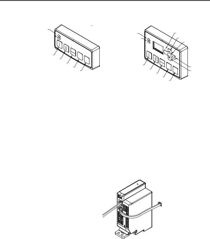
Optional Operator Station
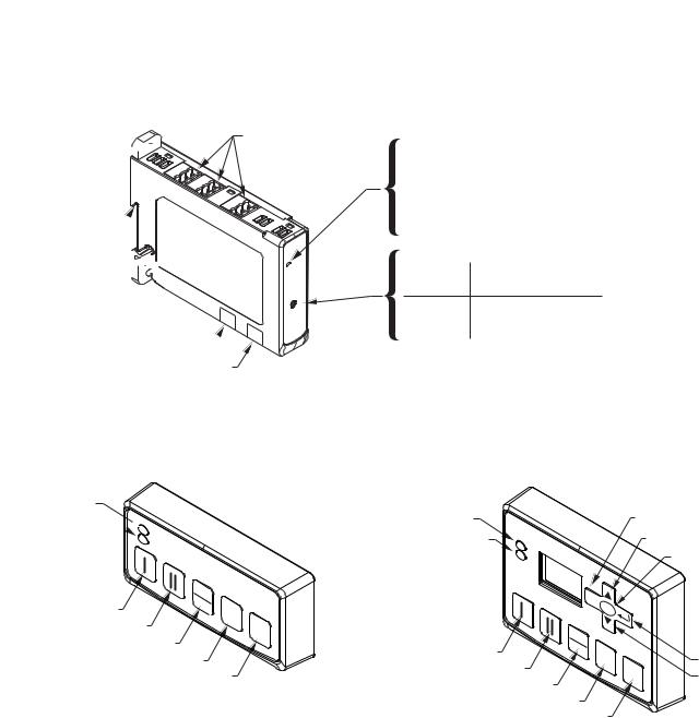
Figure 4 - Operator Stations
Power LED
Trip / Warn LED

|
LOCAL |
|
Start Forward / Speed 1 |
REMOTE |
0 |
|
|
|
Start Reverse / Speed 2 |
|
RESET |
|
|
Local / Remote
Stop
Reset
Control Station
Power LED |
|
|
Escape |
|
Trip / Warn LED |
|
|
Up |
|
|
|
|
|
Select |
|
|
ESC |
|
|
|
|
SELECT |
|
|
|
LOCAL |
|
|
|
Start Forward / Speed 1 |
REMOTE |
0 |
|
Enter |
|
|
|||
Start Reverse / Speed 2 |
|
RESET |
||
|
|
Down |
||
Local / Remote |
|
|
||
|
|
|
|
|
|
Stop |
|
|
|
Reset
Diagnostic Station
The E300 Electronic Overload Relay offers the user the capability to add one operator interface to the Expansion Bus. There are two types of operator stations that the user can chose from: control station or a diagnostic station. Both types of operator stations mount into a standard 22 mm push button knockout, and they provides diagnostic LEDs which allow the user to view the status of the E300 Electronic Overload Relay from the outside of an electrical enclosure. Both operator stations provide push buttons which can be used for motor control logic, and they both can be used to upload and download parameter configuration data from the base relay. The diagnostic station contains a display and navigation buttons that allows the user to view and edit parameters in the base relay.
Optional Expansion Bus Power Supply
Figure 5 - Expansion Bus Power Supply
The E300 Electronic Overload Relay expansion bus provides enough current to operate a system that has (1) Digital Expansion Module and (1) Operator Station. An E300 Electronic Overload Relay system that contains more expansion modules will need supplemental current for the Expansion Bus. The E300 Electronic Overload Relay offers users two types of Expansion Bus Power Supplies: AC (110…240V AC, 50/60 Hz) and DC (24V DC). One Expansion Bus Power Supply supplies enough current for a fully loaded E300 Electronic
18 |
Rockwell Automation Publication 193-UM015B-EN-P - June 2014 |

Product Overview Chapter 1
|
Overload Relay Expansion Bus (four Digital Expansion Modules, four Analog |
|
Expansion Modules, and one Operator Station). |
Protection Features |
Standard Current-Based Protection |
All versions of the E300 Electronic Overload Relay provide the following motor protection functions:
•Thermal Overload (51)
•Phase Loss
•Current Imbalance (46)
•Undercurrent – load loss (37)
•Overcurrent – load jam (48)
•Overcurrent – load stall
•Start Inhibit (66)
Ground Fault Current Based Protection
The E300 Electronic Overload Relay sensing modules and control modules with a ground fault current option provides the following motor protection function:
• Ground Fault – zero sequence method (50N)
Voltage and Power Based Protection
The E300 Electronic Overload Relay sensing modules with voltage sensing provides the following motor protection functions:
•Undervoltage (27)
•Overvoltage (59)
•Phase Reversal (47) – voltage based
•Over and Under Frequency (81) – voltage based
•Voltage Imbalance (46)
•Over and Under Power (37)
•Over and Under Leading/Lagging Power Factor (55)
•Over and Under Reactive Power Generated
•Over and Under Reactive Power Consumed
•Over and Under Apparent Power
Rockwell Automation Publication 193-UM015B-EN-P - June 2014 |
19 |

Chapter 1 Product Overview
Applications: |
The E300 Electronic Overload Relay can be used with the following across the |
|
line starter applications: |
|
• Non-Reversing Starter |
|
• Reversing Starter |
|
• Wye (Star) / Delta Starter |
|
• Two-speed Motors |
|
• Low and Medium Voltage with 2 or 3 Potential Transformers |
|
• With or Without Phase Current Transformers |
|
• With or Without Zero-sequence Core Balanced Current Transformer |
20 |
Rockwell Automation Publication 193-UM015B-EN-P - June 2014 |
Chapter 2
Installation and Wiring
Introduction
Receiving
Unpacking/Inspecting
Storing
This chapter provides instructions for receiving, unpacking, inspecting, and storing the E300™ Electronic Overload Relay. Assembly, installation, and wiring instructions for common applications are also included in this chapter.
It is the responsibility of the user to thoroughly inspect the equipment before accepting the shipment from the freight company. Check the item(s) received against the purchase order. If any items are damaged, it is the responsibility of the user not to accept delivery until the freight agent has noted the damage on the freight bill. Should any concealed damage be found during unpacking, it is again the responsibility of the user to notify the freight agent. The shipping container must be left intact and the freight agent should be requested to make a visual inspection of the equipment.
Remove all packing material from around the E300 Electronic Overload Relay. After unpacking, check the item’s nameplate catalog number against the purchase order.
The E300 Electronic Overload Relay should remain in its shipping container prior to installation. If the equipment is not to be used for a period of time, it must be stored according to the following instructions in order to maintain warranty coverage:
•Store in a clean, dry location.
•Store within an ambient temperature range of -40…+85 °C (-40…+185 °F).
•Store within a relative humidity range of 0…95%, non-condensing.
•Do not store where the device could be exposed to a corrosive atmosphere.
•Do not store in a construction area.
Rockwell Automation Publication 193-UM015B-EN-P - June 2014 |
21 |
Chapter 2 Installation and Wiring
General Precautions
Base Relay Assembly
If the E300 Electronic Overload Relay is being deployed in an environment with an ambient temperature greater than 30 °C (86 °F), please refer to the Environmental Specifications on page 325 for the appropriate temperature derating. In addition to the specific precautions listed throughout this manual, the following general statements must be observed.
ATTENTION: The E300 Electronic Overload Relay contains electrostatic discharge (ESD) sensitive parts and assemblies. Status control precautions are required when installing, testing, servicing, or repairing this assembly. Component damage may result if ESD control procedures are not followed. If you are not familiar with static control procedures, refer to Allen-Bradley publication 8000-SB001_-en-p, “Guarding Against Electrostatic Damage”, or any other applicable ESD protection handbook.
ATTENTION: An incorrectly applied or installed E300 Electronic Overload Relay can result in damage to the components or reduction in product life. Wiring or application errors (e.g., incorrectly figuring the FLA setting, supplying incorrect or inadequate supply voltage, connecting an external supply voltage to the thermistor terminals, or operating or storing in excessive ambient temperatures) may result in malfunction of the E300 Electronic Overload Relay.
ATTENTION: Only personnel familiar with the E300 Electronic Overload Relay and associated machinery should plan to install, start up, and maintain the system. Failure to comply may result in personal injury or equipment damage.
ATTENTION: The purpose of this user manual is to serve as a guide for proper installation. The National Electrical Code (NEC) and any other governing regional or local code will overrule this information. Rockwell Automation cannot assume responsibility for the compliance or proper installation of the
E300 Electronic Overload Relay or associated equipment. A hazard of personal injury and/or equipment damage exists if codes are ignored during installation.
ATTENTION: The earth ground terminal of the E300 Electronic Overload Relay shall be connected to a solid earth ground via a low-impedance connection.
The following section illustrates the E300 Electronic Overload Relay base relay assembly instructions.
22 |
Rockwell Automation Publication 193-UM015B-EN-P - June 2014 |
Installation and Wiring |
Chapter 2 |
|
|
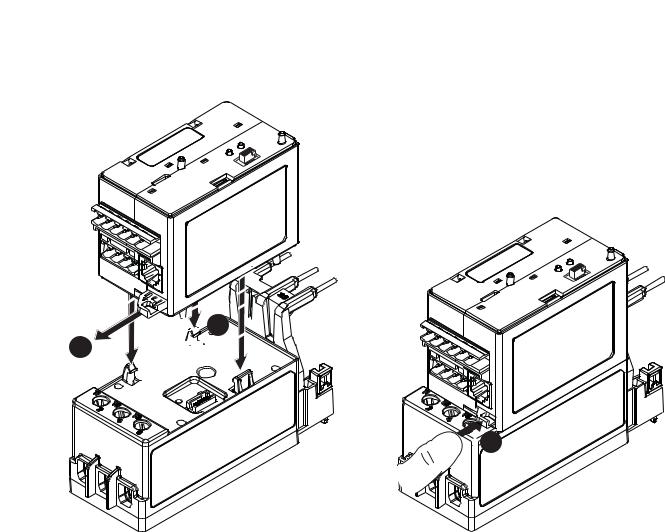
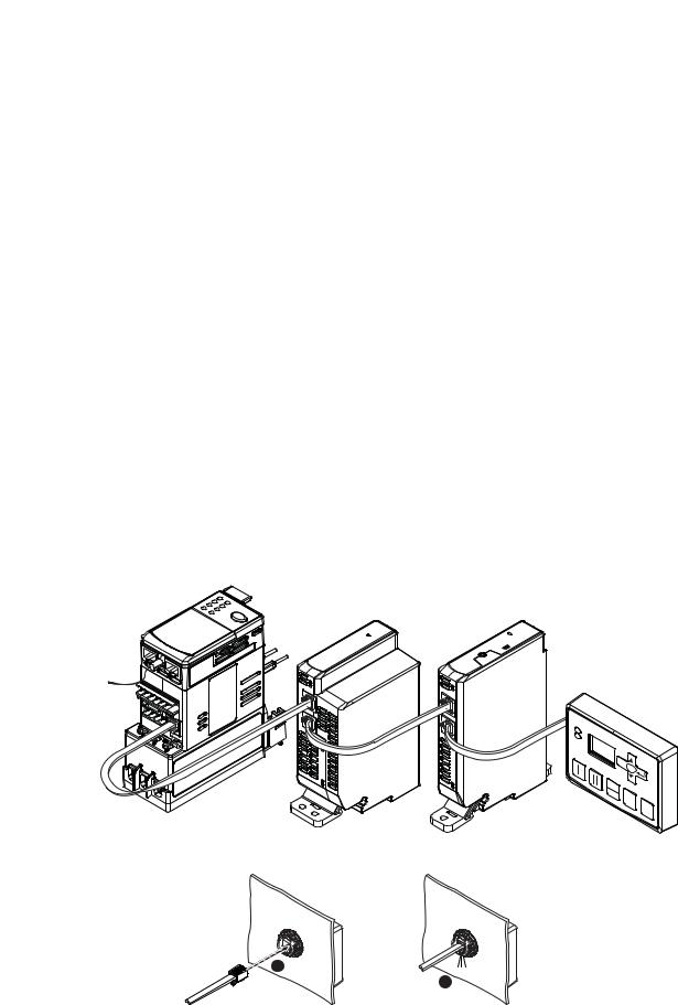
Control Module to Sensing Module Assembly
Any E300 Control Module can connect to any E300 Sensing Module. The illustrations below show the steps required to make this connection.
Figure 6 - Control Module to Sensing Module Assembly\


 2
2

 1
1 


 3
3
Rockwell Automation Publication 193-UM015B-EN-P - June 2014 |
23 |
Chapter 2 Installation and Wiring
Communication Module to Control Module Assembly
Any E300 Communication Module can connect to any E300 Control Module. The illustrations below show the steps required to make this connection.
Figure 7 - Communication Module to Control Module Assembly
2
3
1
24 |
Rockwell Automation Publication 193-UM015B-EN-P - June 2014 |
Installation and Wiring |
Chapter 2 |
|
|
Expansion Bus Peripherals
Panel Mount

Hole
DIN Rail Mount
Panel Mount Hole


Expansion Bus Out
Expansion Bus In
The E300 Electronic Overload Relay offers a range of Expansion Digital and Analog I/O modules that simply connect to the E300 Electronic Overload Relay’s Expansion Bus.
Figure 8 - Expansion Bus Peripherals
Removable I/O Terminals
2 |
3 |
4 |
|
||
1 |
|
4T |
1T |
3T |
|
2T |
|
|
Status LED
Color |
Description |
|
Off |
No power applied |
|
Blinking Green |
Module OK with no connection |
|
Green |
Module OK and active |
|
Red |
Error Detected |
|
Module Number Selector |
|
|
Number |
Description |
|
1 - 4 |
Module number |
|
Module number with 1T - 4T expansion bus terminating
resistor applied
Note: If the expansion bus does not have an operator station, then the last expansion module number must be set to terminated.
Users can also add one of the two available operator stations to the end of the Expansion Bus.
Figure 9 - Expansion Operator Stations
Power LED
Trip / Warn LED

|
LOCAL |
|
Start Forward / Speed 1 |
REMOTE |
0 |
|
|
|
Start Reverse / Speed 2 |
|
RESET |
|
|
Local / Remote
Stop
Reset
Control Station
Power LED |
|
|
Escape |
|
Trip / Warn LED |
|
|
Up |
|
|
|
|
|
Select |
|
|
ESC |
|
|
|
|
SELECT |
|
|
|
LOCAL |
|
|
|
Start Forward / Speed 1 |
REMOTE |
0 |
|
Enter |
|
|
|||
Start Reverse / Speed 2 |
|
RESET |
||
|
|
Down |
||
Local / Remote |
|
|
||
|
|
|
|
|
|
Stop |
|
|
|
Reset
Diagnostic Station
The following illustrations show how to mount and connect the E300 Electronic Overload Relay expansion bus I/O modules, expansion power supplies, and operator stations.
Rockwell Automation Publication 193-UM015B-EN-P - June 2014 |
25 |
Chapter 2 Installation and Wiring
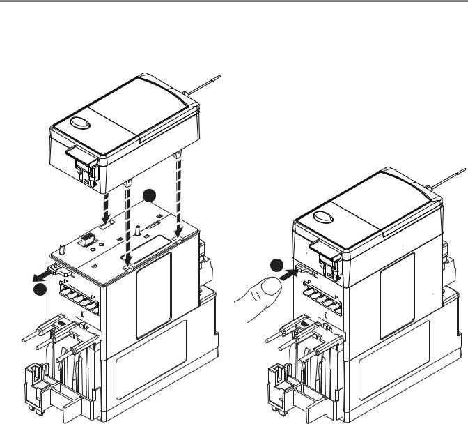
Expansion Bus Digital & |
Figure 10 - Expansion Bus Digital& Analog I/O Modules and Power Supply |
Analog I/O Modules and |
|
Power Supply Installation |
|
1 |
Click |
2
Expansion Bus Operator
Station Installation
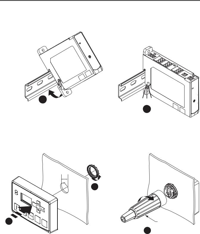
Figure 11 - Expansion Bus Operator Station
22 mm
2
|
C |
|
ES |
|
SE CT |
|
LE |
1 |
0 |
RESET |
800F-AW2
3
Expansion Bus Network
Installation
The E300 Electronic Overload Relay will support up (4) Expansion Digital I/O modules, (4) Expansion Analog I/O modules, and (1) Operation Station. The E300 Base Relay can supply enough power for (1) Expansion Digital I/O module
and (1) Operator Station. Any other combination of E300 Expansion Bus
26 |
Rockwell Automation Publication 193-UM015B-EN-P - June 2014 |
Installation and Wiring |
Chapter 2 |
|
|
peripherals will require an Expansion Bus Power Supply which connects as the first module on the Expansion Bus.
Users will set the address dial of the Expansion Digital Module to a unique digital module address number (1-4). If the Expansion Digital Module is the last device on the Expansion Bus, set the address to the address value that enables in the internal terminating resistor (1T-4T). A power cycle is required when changes are made to the address dial.
Users will set the address dial of the Expansion Analog Module to a unique analog module address number (1-4). If the Expansion Analog Module is the last device on the Expansion Bus, set the address to the address value that enables in the internal terminating resistor (1T-4T). A power cycle is required when changes are made to the address dial.
Users will connect the E300 Base Relay to the Expansion Module’s Input Port using the supplied Expansion Bus cable. Users will add the next Expansion Module by connecting the supplied Expansion Bus cable to the Output Port of the previous Expansion Module and into the Input Port of the additional Expansion Module. The Operator Stations is the last device on the E300 Expansion Bus; it only has an Input Port with an internal Expansion Bus terminating resistor.
If the user supplied Expansion Bus cable is not long enough for the installation, 1-meter (Cat. No. 193-EXP-CBL-1M) and 3-meter (Cat. No. 193-EXP-CBL-3M) Expansion Bus cables are available as accessories. The E300 expansion bus can support a maximum distance of 5 meters (16 ft.).
Figure 12 - Expansion Bus Network Installation
|
ESC |
|
SELECT |
LOCAL |
|
REMOTE |
0 |
|
|
|
RESET |
1 |
Click |
|
2
Rockwell Automation Publication 193-UM015B-EN-P - June 2014 |
27 |
Chapter 2 Installation and Wiring
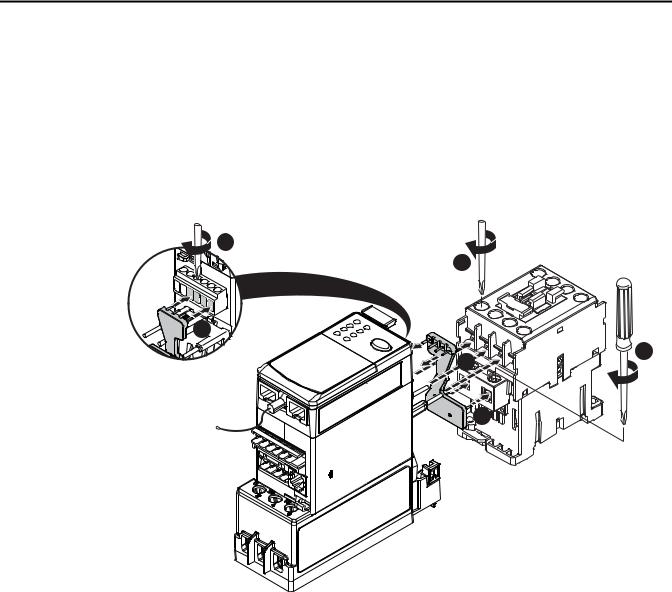
Starter Assembly
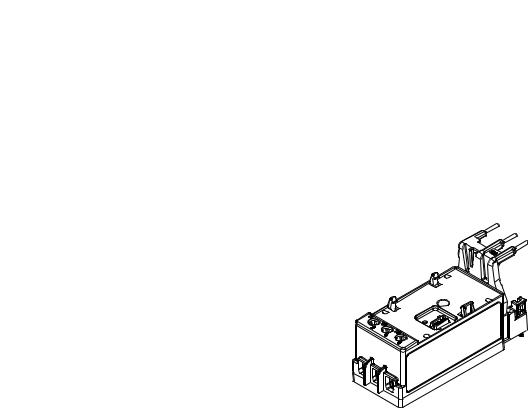
The following illustrations show how to assemble an E300 Electronic Overload Relay as a motor starter with an Allen-Bradley Bulletin 100-C contactor.
100-C09…-C55 Starter Assembly Installation
The starter assembly installation instructions are for use with E300 Sensing Module catalog numbers 193-ESM-___-___-C23 and 193-ESM-___-___-C55
Figure 13 - 100-C09…-C55 Starter Assembly Installation
5 - 7 lb-in
|
|
|
|
|
6 |
|
|
|
|
|
|
5 |
9 - 22 lb-in |
IN1 |
|
|
|
|
|
|
IN0 |
A2 |
|
|
|
|
|
|
R04 |
|
|
|
||
|
|
R03 |
|
|
||
|
|
|
A1 |
|
||
|
|
|
|
|
||
|
|
|
|
|
|
|
|
|
|
4 |
|
|
|
|
|
|
|
|
3 |
2 |
|
|
|
|
|
|
|
|
|
|
|
|
|
7 -11 lb-in |
|
|
|
|
|
|
1 |
28 |
Rockwell Automation Publication 193-UM015B-EN-P - June 2014 |

Installation and Wiring |
Chapter 2 |
|
|
Starter Dimensions
Approximate dimensions are shown in millimeters (inches). Dimensions are not intended to be used for manufacturing purposes.
Figure 14 - E300 Sensing Module 193-ESM-___-__-C23 with 100-C09…-C23 Contactor
45 |
87 |
(1.76) |
(3.40) |
|
190 (7.49) |
|
|
(ADD 5 mm (0.19 in.) |
|
|
FOR CONTACTOR COIL |
|
|
ON LINE SIDE) |
|
|
67 (2.65) |
|
37 (1.47) |
FROM |
|
|
CONTACTOR |
|
|
MTG. HOLE |
|
|
152 (5.98) |
|
122 (4.81) |
|
|
|
29 (1.14) |
122 |
|
(4.78) |
|
|
FROM |
|
|
|
|
|
CONTACTOR |
|
|
MTG. HOLE |
|
35 |
(1.37) |
n 5 (0.18) |
60 (2.3 |
|
|
Figure 15 - E300 Sensing Module 193-ESM-___-__-C55 with 100-C30…-C37 Contactor |
|
|
|
45 |
104 |
35 |
|
|
(1.76) |
|
||
|
(1.374) |
|
||
|
(4.10) |
|
||
|
|
|
||
|
|
n 5 (0.18) |
|
|
|
|
|
|
|
|
|
190 (7.49) |
|
60 (2.36 |
|
|
(ADD 5 mm (0.19 in.) |
|
|
|
|
FOR CONTACTOR COIL |
|
|
|
|
ON LINE SIDE) |
|
|
|
|
67 (2.65) |
|
|
37 (1.48) |
FROM |
|
|
|
|
CONTACTOR |
|
|
|
|
MTG. HOLE |
|
|
|
|
|
152 (5.98) |
|
|
122 (4.81)
29 (1.13) |
|
|
|
|
|
|
|
|
|
|
|
|
|
FROM |
|
|
|
|
|
|
CONTACTOR |
122 |
|||||
MTG. HOLE |
|
|
|
|
|
|
|
(4.78) |
|||||
Rockwell Automation Publication 193-UM015B-EN-P - June 2014 |
29 |
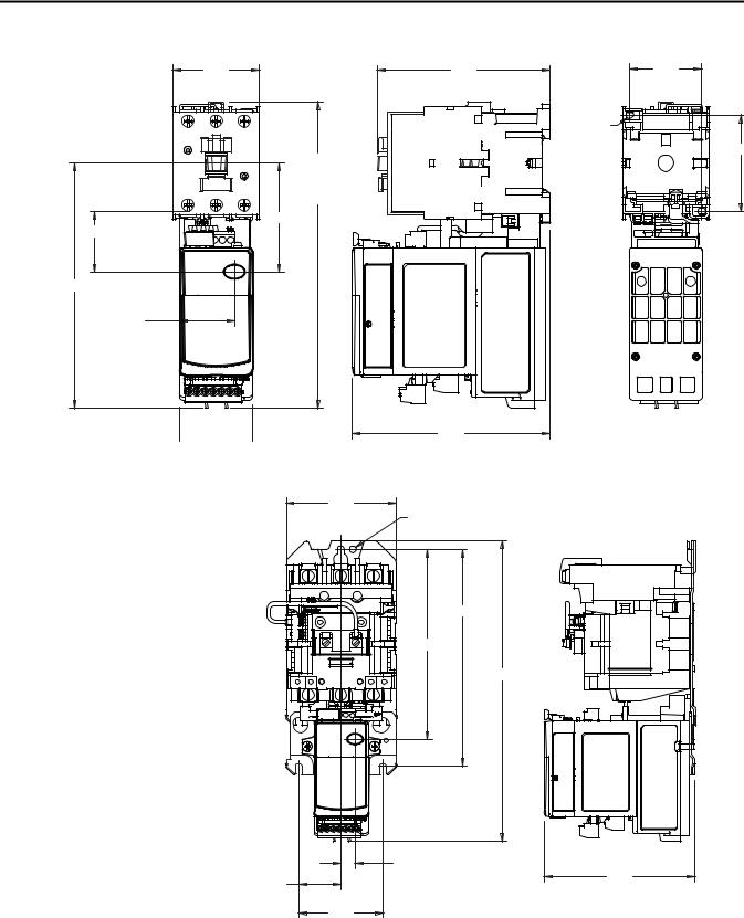
Chapter 2 Installation and Wiring
Figure 16 - E300 Sensing Module 193-ESM-___-__-C55 with 100-C43…-C55 Contactor
54
(2.12)
|
190 (7.49) |
|
(ADD 5 mm (0.19 in.) |
|
FOR CONTACTOR COIL |
|
ON LINE SIDE) |
|
67 (2.65) |
37 (1.48) |
FROM |
|
CONTACTOR |
|
MTG. HOLE |
152 (5.98) |
|
|
34 (1.34) |
|
FROM |
|
CONTACTOR |
|
MTG. HOLE |
 45 (1.76)
107 |
(4.21) |
122 |
(4.82) |
45 (1.75) |
n 5 (0.18) |
60 (2. |
Figure 17 - E300 Sensing Module 592-ESM-___-__-S2 with NEMA Contactor Size 0 and Size 1
|
90 |
|
(3.56) |
|
n 6 (0.22) |
|
180 (7.06) |
|
157 (6.17) |
|
249 (9.78) |
|
12 (0.46) |
|
35 (1.38) |
|
70 |
|
(2.75) |
30 |
Rockwell Automation Publication 193-UM015B-EN-P - June 2014 |
125 |
(4.91) |
Loading...