


 Loading...
CS3000 MMI SW-Version 6.1 Control and Configuration Software
for FlexPak3000 V2.0 - 4.3,
GV3000 V2.0 - 6.0 and Liqui-Flo
Instruction Manual
Manual P/N: 899.05.84 |
User Manual: 49‘1307e (04) |
Firmware P/N: 788.05.30 |
Publication: CS3000-UM003D-EN |
|
|
The information in this manual is subject to change without notice.
Throughout this manual, the following notes are used to alert you to safety considerations:
ATTENTION: Identifies information about practices or circumstances that can lead to personal
injury or death, property damage, or economic loss.
!
Important: Identifies information that is critical for successful application and understanding of the product.
The thick black bar shown on the outside margin of this page will be used throughout this instruction manual to signify new or revised text or figures.
ATTENTION: Only qualified electrical personnel familiar with the construction and operation of this equipment and the hazards involved should install, operate, or service this equipment. Read
!and understand this manual and other applicable manuals in their entirety before proceeding. Failure to observe this precaution could result in severe bodily injury or loss of life.
ATTENTION: Only qualified personnel should develop or change drive configuration. Read and understand the drive instruction manual in its entirety before proceeding with configuration edit. Failure to observe this precaution could result in severe bodily injury or loss of life.
ATTENTION: Parameter assignments made while the software in controlling and communicating to the drive overwrite the parameter values in the drive. Read and understand this manual and all other applicable manuals in their entirety before changing drive parameter values. Failure to observe this precaution could result in severe bodily injury or loss of life.
IBM is a trademark of International Business Machine Corporation. Microsoft, Windows, and MS-DOS are trademarks of Microsoft Corporation. Pentium is a trademark of Intel Corporation.
GV3000, Liqui-Flo, FlexPak, and Reliance are trademarks of Rockwell Automation.
©1999 Rockwell International Corporation

CONTENTS
Chapter 1 |
Introduction |
|
|
|
1.1 |
About the Control and Configuration Software ................................................ |
1-1 |
|
1.2 |
Software Requirements ................................................................................... |
1-1 |
|
1.3 |
Hardware Requirements.................................................................................. |
1-2 |
|
1.4 |
Cables ............................................................................................................. |
1-2 |
|
1.5 |
Safety Information ........................................................................................... |
1-3 |
|
1.6 |
Purpose of This Manual................................................................................... |
1-3 |
|
1.7 |
Intended Audience........................................................................................... |
1-3 |
|
1.8 |
Terms Used in This Manual............................................................................. |
1-4 |
|
1.9 |
Where to Find Additional Information .............................................................. |
1-4 |
Chapter 2 Getting Started |
|
||
2.1 |
Before Installing the Software.......................................................................... |
2-1 |
|
2.2 |
Installing the CS3000 Software on a Personal Computer ............................... |
2-2 |
|
2.3 |
Setting Up Communication Between the CS3000 Software and the Drive ..... |
2-3 |
|
|
2.3.1 Connecting the Personal Computer’s Serial Port to the Drive .............. |
2-3 |
|
|
2.3.2 Setting Up the Drive to Communicate with the Personal Computer...... |
2-5 |
|
|
2.3.3 Selecting the Correct Communication Port ........................................... |
2-5 |
|
2.4 |
Starting the Software ....................................................................................... |
2-5 |
|
2.5 |
About the Menus and Toolbars ....................................................................... |
2-7 |
|
|
2.5.1 |
About the Menus ................................................................................... |
2-7 |
|
2.5.2 |
About the Toolbar.................................................................................. |
2-8 |
2.6 |
Exiting the CS3000 Software......................................................................... |
2-10 |
|
Chapter 3 Configuring the Drive |
|
||
3.1 |
Selecting a Drive ............................................................................................. |
3-1 |
|
3.2 |
Creating a New Configuration ......................................................................... |
3-2 |
|
3.3 |
Opening a Drive Configuration File ................................................................. |
3-3 |
|
3.4 |
Opening a Configuration File for a Different Version of the Same Drive ......... |
3-5 |
|
3.5 |
Editing a Configuration .................................................................................... |
3-7 |
|
|
3.5.1 |
Assigning Parameter Values ................................................................. |
3-7 |
|
3.5.2 Ending an Editing Session .................................................................... |
3-9 |
|
|
3.5.3 Entering and Editing a Configuration Description.................................. |
3-9 |
|
3.6 |
Saving a Drive Configuration......................................................................... |
3-10 |
|
3.7 |
Saving the Open Drive Configuration to Another File.................................... |
3-11 |
|
3.8 |
Printing a Configuration ................................................................................. |
3-12 |
|
Chapter 4 Uploading and Downloading Drive Configurations |
|
||
4.1 |
Uploading a Drive Configuration...................................................................... |
4-1 |
|
4.2 |
Downloading a Configuration to the Drive ....................................................... |
4-2 |
|
4.3 |
Comparing the Drive Configuration to the Opened Configuration ................... |
4-3 |
|
4.4 |
Comparing the Parameter Values in the Opened Configuration with |
|
|
|
Those in Another Configuration File ................................................................ |
4-4 |
|
Contents |
I |

Chapter 5 Tuning GV3000 and Liqui-Flo Vector Drives |
|
||
5.1 |
Saving the Drive Configuration Before Tuning................................................. |
5-2 |
|
5.2 |
Using Standard Tuning .................................................................................... |
5-2 |
|
5.3 |
Using Custom Tuning....................................................................................... |
5-5 |
|
|
5.3.1 |
Setting Motor Data ................................................................................ |
5-5 |
|
5.3.2 |
Tuning the Torque/Flux Loop ................................................................ |
5-6 |
|
5.3.3 Tuning the Speed Loop ......................................................................... |
5-7 |
|
|
5.3.4 Using Profile To Check Drive Tuning..................................................... |
5-9 |
|
Chapter 6 Monitoring and Editing Drive Parameters |
|
||
6.1 |
About the Parameter Monitor ........................................................................... |
6-1 |
|
6.2 |
Adding Parameters to the Monitor List............................................................. |
6-3 |
|
6.3 |
Removing Parameters from the Monitor List.................................................... |
6-3 |
|
6.4 |
Assigning Values to Parameters on the Drive.................................................. |
6-4 |
|
6.5 |
Saving a Monitor List........................................................................................ |
6-6 |
|
6.6 |
Displaying a Monitor List .................................................................................. |
6-7 |
|
6.7 |
Clearing the Monitor List Display ..................................................................... |
6-8 |
|
6.8 |
Exiting the CS3000 Parameter Monitor............................................................ |
6-8 |
|
Chapter 7 Monitoring Drive Status and Alarms |
|
||
7.1 |
Displaying and Clearing the Fault Log and Alarm Log..................................... |
7-1 |
|
7.2 |
Monitoring Drive Status.................................................................................... |
7-4 |
|
7.3 |
Restoring Default Values to Drive Parameters ................................................ |
7-5 |
|
7.4 |
Saving Drive Parameter Values to Non-Volatile Memory on the Drive ............ |
7-5 |
|
7.5 |
Restoring Drive Parameter Values from Non-Volatile Memory in the Drive..... |
7-6 |
|
Chapter 8 Controlling the Drive |
|
||
8.1 |
Connecting a Drive........................................................................................... |
8-1 |
|
8.2 |
Disconnecting a Drive ...................................................................................... |
8-1 |
|
8.3 |
Controlling a Drive............................................................................................ |
8-2 |
|
8.4 |
Selecting the Control Source ........................................................................... |
8-4 |
|
8.5 |
Selecting the Reference Mode (Auto/Manual) ................................................. |
8-4 |
|
8.6 |
Selecting the Direction of Motor Rotation......................................................... |
8-4 |
|
8.7 |
Setting the Drive Reference ............................................................................. |
8-4 |
|
8.8 |
Setting the Jog Reference................................................................................ |
8-5 |
|
8.9 |
Starting and Stopping the Drive ....................................................................... |
8-5 |
|
8.10 |
Monitoring Drive Indicators .............................................................................. |
8-6 |
|
Chapter 9 Using PC Scope |
|
||
9.1 |
About PC Scope............................................................................................... |
9-1 |
|
9.2 |
Setting Up a Trace ........................................................................................... |
9-4 |
|
|
9.2.1 |
Specifying Signals ................................................................................. |
9-5 |
|
9.2.2 Setting Up Data Sampling ..................................................................... |
9-5 |
|
|
9.2.3 Setting Up the Trigger............................................................................ |
9-6 |
|
9.3 |
Acquiring a Trace ............................................................................................. |
9-7 |
|
9.4 |
Working with the Cursors ................................................................................. |
9-8 |
|
|
9.4.1 |
Moving a Cursor .................................................................................... |
9-9 |
|
9.4.2 Specifying the Cursors To Track Each Other ........................................ |
9-9 |
|
9.5 |
Changing Views ............................................................................................... |
9-9 |
|
|
9.5.1 Turning Cursors On and Off .................................................................. |
9-9 |
|
|
9.5.2 Magnifying the Trace Display .............................................................. |
9-10 |
|
9.6 |
Taking a Trace Snapshot ............................................................................... |
9-10 |
|
|
9.6.1 |
Taking a Snapshot............................................................................... |
9-10 |
II |
Control and Configuration Software V6.1 |

|
|
9.6.2 Choosing the Trace Snapshot Colors |
................................................. 9-11 |
|
9.7 |
Saving a Trace File........................................................................................ |
9-11 |
|
9.8 |
Clearing the Trace Display and Setup........................................................... |
9-12 |
|
9.9 |
Opening a Trace File ..................................................................................... |
9-12 |
|
9.10 |
Closing PC Scope ......................................................................................... |
9-13 |
Chapter 10 |
Troubleshooting |
|
|
|
10.1 |
Using Error Messages ................................................................................... |
10-1 |
|
10.2 |
Getting Assistance from Reliance Electric..................................................... |
10-1 |
Appendix A |
Error Messages ........................................................................................................ |
A-1 |
|
Appendix B New Features in Version 6.1 .................................................................................... |
B-1 |
||
Index |
........................................................................................................................... |
|
Index-1 |
Contents |
III |

IV |
Control and Configuration Software V6.1 |

List of Figures
Figure 2.1 – RS-232 Cable Connector Pinouts for Drives with a 9-Pin Connector |
... 2-4 |
Figure 2.2 – RS-232 Cable Connector Pinouts for Drives with a Terminal |
|
Block Connector ................................................................................... |
2-4 |
Figure 2.3 – RS-232 Cable Connector Pinouts for Drives with a 25-Pin |
|
Connector............................................................................................. |
2-5 |
Figure 2.4 – Sample Main Window for an Established Connection.......................... |
2-6 |
Figure 2.5 – Graphical Tool Bar................................................................................ |
2-8 |
Figure 3.1 – Drive Select—Disconnected................................................................. |
3-1 |
Figure 3.2 – File New Window.................................................................................. |
3-2 |
Figure 3.3 – Open Configuration File Dialog Box ..................................................... |
3-3 |
Figure 3.4 – Configuration Editor.............................................................................. |
3-7 |
Figure 3.5 – Configuration Description Dialog Box................................................... |
3-9 |
Figure 3.6 – Configuration Description Pop-Up Edit Menu..................................... |
3-10 |
Figure 3.7 – Save Configuration Dialog Box........................................................... |
3-11 |
Figure 3.8 – Sample Configuration File Printout..................................................... |
3-12 |
Figure 4.1 – Compare Configuration File Dialog Box ............................................... |
4-4 |
Figure 4.2 – Configuration Differences Dialog Box................................................... |
4-5 |
Figure 5.1 – Drive Tuning Menu ............................................................................... |
5-1 |
Figure 5.2 – Example of Motor Data Dialog Box ...................................................... |
5-2 |
Figure 5.3 – Example of Setting Motor Data Values................................................. |
5-4 |
Figure 5.4 – Example of Setting Torque/Flux Loop Data Values.............................. |
5-5 |
Figure 5.5 – Example of Setting Speed Loop Data Values ...................................... |
5-6 |
Figure 5.6 – Drive Profile Example ........................................................................... |
5-7 |
Figure 6.1 – Parameter Monitor Window .................................................................. |
6-2 |
Figure 6.2 – Add Parameters to Monitor List Dialog Box.......................................... |
6-3 |
Figure 6.3 – Save Monitor List Dialog Box ............................................................... |
6-6 |
Figure 6.4 – Recall Monitor List Dialog Box.............................................................. |
6-7 |
Figure 6.5 – Remove Parameters from Monitor List Dialog Box .............................. |
6-8 |
Figure 7.1 – Sample Fault Log List Box.................................................................... |
7-1 |
Figure 7.2 – Sample Alarm Log List Box .................................................................. |
7-2 |
Figure 7.3 – Drive Status Window ............................................................................ |
7-4 |
Figure 8.1 – Drive Control Window........................................................................... |
8-3 |
Figure 9.1 – The PC Scope Screen.......................................................................... |
9-2 |
Figure 9.2 – Trace Signal Setup Dialog Box............................................................. |
9-4 |
Figure 9.3 – Sample Trace ....................................................................................... |
9-8 |
Figure 9.4 – Save a Signal Trace File Dialog Box .................................................. |
9-11 |
Figure 9.5 – Open Signal Trace File Dialog Box .................................................... |
9-12 |
Contents |
V |

VI |
Control and Configuration Software V6.1 |

|
|
List of Tables |
Table 1.1 – Cables.................................................................................................... |
1-2 |
|
Table 1.2 – Terms..................................................................................................... |
1-4 |
|
Table 2.1 – Overview of the Menu............................................................................ |
2-7 |
|
Table 2.2 – Toolbar Icons and Menus ...................................................................... |
2-9 |
|
Table 3.1 – Editing Configuration Descriptions....................................................... |
3-10 |
|
Table 4.1 – Compare Dialog Box Functions ............................................................. |
4-3 |
|
Table 4.2 |
– Configuration Differences Dialog Box Options ...................................... |
4-5 |
Table 7.1 |
– Using the Fault and Alarm Logs ............................................................ |
7-3 |
Table 7.2 |
– Drive Status Indicators........................................................................... |
7-5 |
Table 9.1 |
– PC Scope Toolbar Buttons .................................................................... |
9-3 |
Contents |
VII |

VIII |
Control and Configuration Software V6.1 |
CHAPTER 1
Introduction
This section describes the computer requirements for the CS3000 software and presents general information about the software and this manual.
1.1About the Control and Configuration Software
Use the Control and Configuration (CS3000) software to help you develop drive configurations on your personal computer for GV3000ä, Liqui-Floä, and
FlexPakä 3000 drives. The CS3000 software communicates with the drive through the personal computer’s RS-232 port.
By using the CS3000 software, you can:
•Create, store, upload, download, and print drive configurations.
•Monitor drive status.
•Monitor and change drive parameters using a personal computer.
•Control the drive (start, stop, etc.).
•Compare a configuration in the drive with one in the personal computer.
•Read and reset the drive fault and error log.
•Create, modify, and store drive configurations.
•Send Memory Save, Memory Restore, and Restore Defaults commands to a drive.
•Display trace signals in the drive.
1.2Software Requirements
The CS3000 software requires Microsoft Windowsä 3.1 or later versions (including Windows 98 or Windows NT). Make sure Windows is installed and configured on your personal computer before attempting to install the CS3000 software.
Introduction |
1-1 |

1.3Hardware Requirements
Before installing and using the CS3000 software make sure you have the following hardware:
•An IBM or IBM-compatible 486 or Pentium personal computer running Windows 3.1, Windows 98, or Windows NT.
•16 Mbytes of RAM (minimum)
•A hard drive with at least 1 Mbytes free space available for the CS3000 software
•A 3.5" floppy drive
•A Monochrome or color monitor: VGA or better
•An RS-232 serial COM port for communicating with the drive
•An RS-232 serial cable with:
•A 25-pin or 9-pin D-shell connector for your personal computer
•A 9-pin or 25-pin male D-shell connector for the drive.
The GV3000 drive is equipped with a terminal strip as well as a 9-pin D-shell connector. Either one can be used to connect to the personal computer. Refer to section 2.3.1 for additional information.
1.4Cables
The Interface cable can be used to connect the personal computer to the drive.
The Adapter is required, if your personal computer has a 25-pin COM port and you want to use one of the specified Interface cables.
Table 1.1 - Cables
Drive |
Drive |
PC |
Interface Cable |
Adapter |
Cable |
|
Connector |
Connector |
|
|
Part No. |
FlexPak3000 |
25-pin |
9-pin |
25-pin to 9-pin |
|
772.27.00 |
|
|
25-pin |
|
25-pin to 9-pin |
772.27.20 |
GV3000 |
9-pin |
9-pin |
9-pin to 9-pin |
|
772.27.10 |
Liqui-Flo |
|
25-pin |
|
25-pin to 9-pin |
772.27.20 |
1-2 |
Control and Configuration Software V6.1 |

1.5Safety Information
ATTENTION: Do not run other Windows or DOS software applications while you are using the CS3000 software for drive control. Unexpected
!machine motion could result. Failure to observe this precaution could result in severe bodily injury or loss of life.
The CS3000 software operates as a Windows 3.1 application. It cannot preempt other applications or functions in Windows and, therefore, cannot guarantee a response time to user input actions. Using other applications while controlling a drive with the CS3000 software can tie up PC resources and cause drive commands to be delayed. To prevent drive commands (run, stop, and jog) from unexpectedly executing, the CS3000 software specifies a time-out period (approximately 2 seconds) when it establishes a link with the drive. While the link is established, the CS3000 software sends messages to the drive to validate the link. If a message fails to reach the drive within the time-out period because program execution has been delayed, the drive invalidates the link. If the link becomes invalid, the drive does not accept drive commands. If the drive was running, it stops, and a serial fault is generated.
Before a drive control command is sent to the drive, the drive’s status is checked to validate the link. If communication between the CS3000 software and the drive have been interrupted and you have selected a drive command, the command is not sent and a message is displayed.
The time-out period is also used by the Parameter Monitor and Download functions, both of which could be running while the Drive Control Window is open. If the link becomes invalid while these functions are running, a message will be displayed in the Drive Control window before the link is re-established. When you select the Download command while the Drive Control window is open, you cannot execute drive command controls until the download is complete.
1.6Purpose of This Manual
This manual describes how to use the Control and Configuration software (CS3000) to configure GV3000, Liqui-Flo, and FlexPak 3000 drives. Refer to the appropriate drive instruction manual for information about parameters and RS-232 connection options.
1.7Intended Audience
This manual is written for those who must install the CS3000 software and use the software to configure and run GV3000, Liqui-Flo, and FlexPak drives. This manual assumes you are familiar with Windows and makes references to it throughout.
You will need to know the basic Windows functions before using the CS3000 software.
Introduction |
1-3 |

1.8Terms Used in This Manual
The following terms are used throughout this manual:
|
Table 1.2 – Terms |
|
|
CS3000 |
Control and Configuration |
|
|
COM port |
communication port |
|
|
configuration file |
drive configurations stored on the personal computer that can only be read and |
|
written to by the CS3000 software |
|
|
disk drive |
the personal computer’s 3.5 inch disk drive |
|
|
drive |
the Power Module and regulator combination that controls a motor |
|
Drives can be configured using the CS3000 software. |
|
|
drive configuration |
the set of drive parameters and assignment values that specify how the drive |
|
runs |
|
|
hard drive |
the personal computer’s hard disk drive |
|
|
opened configuration |
the configuration that is active in the CS3000 software |
|
|
1.9Where to Find Additional Information
See the following instruction manuals for more information about the drives that can be configured using the CS3000 software:
•GV3000 AC Drive Instruction Manuals
•Liqui-Flo AC Drive Instruction Manuals
•FlexPak 3000 DC Drive Instruction Manuals
1-4 |
Control and Configuration Software V6.1 |

CHAPTER 2
Getting Started
This section describes how to install the CS3000 software and use the menus and toolbars.
2.1Before Installing the Software
If you have an older version of the CS3000 software on your PC, you should either:
•delete the old version before installing the new version
Keep any working files such as, the drive configuration and monitor list files, for use with the new version of the CS3000 software
•install the new version of CS3000 software in a new directory
You can select the new directory name during installation. If you choose this option, change the name of the program folder for the old version of the CS3000 software to a name other than CS3000, such as “CS3000, V 5.0.” Otherwise, the new version will replace the old version in that program group, although it will not overwrite any of the files on the hard drive. See your Windows documentation for more information about changing the name of a program group.
Before installing the new CS3000 software, back up the files to another floppy disk.
See your Windows documentation for instructions about using the File Manager or Explorer to copy disks.
Getting Started |
2-1 |

2.2Installing the CS3000 Software on a Personal Computer
All files needed to install the CS3000 software are on the 3.5" CS3000 disk. Use the following steps to install the CS3000 software.
Important: To exit installation, select the Exit icon in the lower right corner or press
Step 1. Start Microsoft Windows.
Step 2. Insert the CS3000 software disk into the 3.5" floppy drive.
Step 3. Follow the steps for operating the system you are using:
|
Windows 3.1 |
Windows 98 or NT |
|
|
|
||
a. From the Program Manager |
a. From the Start Menu, select Run. |
||
|
menu bar, select File. |
|
|
|
|
|
|
b. |
Select Run. |
b. In the Open field, type in the |
|
|
|
drive letter followed by SETUP. |
|
c. |
In the Command Line field, |
||
For example, if your 3.5" floppy |
|||
|
type in the drive letter |
||
|
drive is A:, you would type |
||
|
followed by \SETUP.EXE. For |
||
|
A:SETUP |
||
|
example, if your 3.5" floppy |
||
|
The message “Setup is |
||
|
drive is A:, you would type |
||
|
initializing. Please wait . . .” is |
||
|
A:\SETUP.EXE. |
||
|
displayed for about a minute. |
||
|
|
||
|
|
||
d. Select OK. The message |
|
||
|
“Setup is initializing. Please |
|
|
|
wait . . .” is displayed for |
|
|
|
about a minute. |
|
|
|
|
|
|
Step 4. At the prompt “Enter location for Control and Configuration Software program files,” specify the location where you want to install the software. The location defaults to C:\CS3000. Select OK when the drive and directory are correct.
The installation software automatically creates the new directory on the hard drive you enter.
Step 5. At the prompt “Enter desired default location for Control and Configuration Software work files,” specify the location where you want to store the drive configuration files. The default location is C:\CS3000\WORK. Select OK when the drive and directory are correct.
The program begins its installation sequence. You see the following messages during installation:
•“Decompressing Control and Configuration Software files . . .” for about a minute, then
•“Creating Program Group and Icon” for a few seconds
2-2 |
Control and Configuration Software V6.1 |

After creating the program group and icon, the CS3000 software installation is complete. The installation program automatically exits, and you return to Windows. You should see a new program group titled “Control and Configuration.”
Step 6. Remove the CS3000 disk from the 3.5" drive.
The CS3000 software is now installed and ready to use.
If you had an older version of the CS3000 software installed, you can use the configuration and monitor files you created with that version. To make it easier to use the existing configuration and monitor files, move them to the working directory of the new version of software. The working directory is normally C:\CS3000\WORK. Configuration files typically have file extensions of .CNF; monitor files typically have
.MON file extensions. See the Windows documentation for information about moving files.
2.3Setting Up Communication Between the CS3000 Software and the Drive
The following sections describe the setup required for communication between the CS3000 software and the drive. To enable communication between the CS3000 software and the drive:
•Physically connect the personal computer to the drive through a serial port connection (see section 2.3.1)
•Set up the drive for communication through a serial port (see section 2.3.2)
•Select the correct communication port on the personal computer (see section 2.3.3)
2.3.1Connecting the Personal Computer’s Serial Port to the Drive
For the CS3000 software to communicate with the drive, connect the personal computer to the drive using an appropriate cable by following these instructions:
Step 1. The drive’s RS-232 port typically uses a 9-pin or 25-pin female D-shell connector. Connect the communication cable’s 9-pin or 25-pin male connector to the drive. Refer to the drive instruction manual for the location of the RS-232 port on the drive.
Step 2. Connect the other end of the communication cable to the personal computer’s COM1 port. If the COM1 port is not available, refer to section 2.3.3 for information about selecting the correct communication port. The personal computer COM port might have either a 25-pin or a 9-pin connector. Refer to figures 2.1 through 2.3 for cable connector and pinout signals for 9-pin and 25-pin configurations.
Getting Started |
2-3 |

.
Personal Computer |
|
Drive |
||
25-pin Female |
|
9-pin Male |
||
Data OUT |
- 3 |
|
3 - |
Data IN |
|
||||
Data IN |
- 2 |
|
2 - |
Data OUT |
|
||||
Ground |
- 7 |
|
5 - |
Ground |
|
||||
Personal Computer |
|
Drive |
||
9-pin Female |
|
9-pin Male |
||
Data OUT |
- 3 |
|
3 - |
Data IN |
|
||||
Data IN |
- 2 |
|
2 - |
Data OUT |
|
||||
Ground |
- 5 |
|
5 - |
Ground |
|
||||
Figure 2.1 – RS-232 Cable Connector Pinouts for Drives with a 9-Pin Connector
Personal Computer |
|
|
Drive |
||
25-pin Female |
|
Terminal |
|||
Data OUT |
- 3 |
|
2 |
- |
Data IN |
|
|||||
Data IN |
- 2 |
|
1 |
- |
Data OUT |
|
|||||
Ground |
- 7 |
|
3 |
- |
Ground |
|
|||||
Personal Computer |
|
Drive |
||
9-pin Female |
|
Terminal |
||
Data OUT |
- 3 |
|
2 - |
Data IN |
|
||||
Data IN |
- 2 |
|
1 - |
Data OUT |
|
||||
Ground |
- 5 |
|
3 - |
Ground |
|
||||
Figure 2.2 – RS-232 Cable Connector Pinouts for Drives with a Terminal Block Connector
2-4 |
Control and Configuration Software V6.1 |

Personal Computer |
|
|
Drive |
|
25-pin Female |
|
25-pin Male |
||
Data OUT |
- 3 |
|
3 - |
Data IN |
|
||||
Data IN |
- 2 |
|
2 - |
Data OUT |
|
||||
Ground |
- 7 |
|
7 - |
Ground |
|
||||
Personal Computer |
|
|
Drive |
|
9-pin Female |
|
25-pin Male |
||
Data OUT |
- 3 |
|
3 - |
Data IN |
|
||||
Data IN |
- 2 |
|
2 - |
Data OUT |
|
||||
Ground |
- 5 |
|
7 - |
Ground |
|
||||
Figure 2.3 – RS-232 Cable Connector Pinouts for Drives with a 25-Pin Connector
2.3.2 Setting Up the Drive to Communicate with the Personal Computer
For the CS3000 software to communicate with the drive, the drive’s operation control source parameter must be set up properly. For the GV3000, Liqui-Flo, or
FlexPak 3000 drive, set parameter P.000 to specify serial communication. Refer to the appropriate drive instruction manual for more information.
2.3.3 Selecting the Correct Communication Port
The CS3000 software communicates with the drive through the personal computer’s serial port. The software defaults to the COM1 port. If COM1 is already being used, you must select another COM port. To change the COM port:
Step 1. Start the CS3000 software.
Step 2. From the Options menu, select COM.
Step 3. Select the appropriate COM port from the options displayed in the dialog box.
Step 4. Select OK when the correct COM port is selected. This returns you to the CS3000 main window.
2.4Starting the Software
Follow these steps to run the CS3000 software.
Using Windows:
Step 1. Run Windows.
Step 2. When you are in Windows, select the Drive Control and Configuration program group.
Step 3. Double-click the CS3000 icon within the CS3000 program group.
Getting Started |
2-5 |
Using Windows 98:
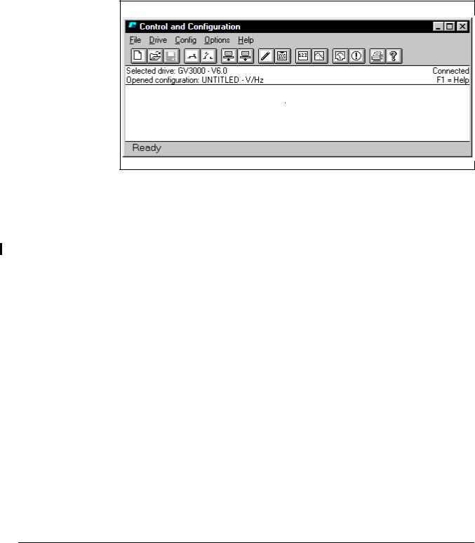
• From the Start menu, choose Programs and Control and Configuration. The CS3000 Main Window is displayed as shown in Figure 2.4.
Figure 2.4 – Sample Main Window for an Established Connection
The CS3000 software tries to establish communication with the drive.
If communication is: |
Then: |
|
|
established |
• The drive type (GV3000, Liqui-Flo, or FlexPak 3000) and version is |
|
displayed in the Selected Drive field. |
|
• “UNTITLED” is displayed in the Opened configuration field. |
|
• Drives that have Vector or Volts/Hertz options display the currently |
|
selected option. |
|
• “Connected” is displayed on the right side of the main window. |
|
• The configuration on the drive is uploaded to the personal |
|
computer. |
|
• The drive status window is automatically opened. See section 6.2 |
|
for more information. |
|
|
not established |
• The Selected Drive field displays either “UNTITLED” or the drive |
|
that was selected the last time the CS3000 software was run. If the |
|
Selected Drive field displays “UNTITLED,” you must select a drive. |
|
See chapter 3 for more information. |
|
• “Disconnected” is displayed on the right side of the main window. |
|
• “UNTITLED” is displayed in the Opened Configuration field. |
|
• Drives that have Vector or Volts/Hertz options display the currently |
|
selected option. |
|
|
2-6 |
Control and Configuration Software V6.1 |
If you want to establish communication, but the CS3000 software is not connecting to the drive:
•Make sure power to the drive is on.
•See section 2.3, Setting Up Communication Between the CS3000 Software and the Drive.
2.5About the Menus and Toolbars
Use the menus and toolbar to navigate through the software as described in the following sections.
2.5.1 About the Menus
Table 2.1 explains the CS3000 software functions you can access through the menu.
|
|
Table 2.1 – Overview of the Menu |
|
|
|
Use this menu: |
|
To: |
|
|
|
File |
Access and manage configuration files |
|
|
|
|
Drive |
• Connect to and disconnect from the drive |
|
|
• |
Select a drive |
|
• |
Control the drive |
|
• View drive status and alarms |
|
|
• Use the PC Scope |
|
|
• Set parameters in the drive to the default values |
|
|
• Save drive parameter values to the drive’s non-volatile |
|
|
|
memory (for drives that support this option) |
|
• Restore values from the drive’s non-volatile memory to its |
|
|
|
run-time memory (for drives that support this option) |
|
• Tune GV3000 or Liqui-Flo drives (vector regulation only) |
|
|
|
|
Config |
• |
Edit a configuration file |
|
• Enter a description for a configuration file |
|
|
• Upload or download a configuration file |
|
|
• Compare a configuration file |
|
|
|
|
Option |
Choose the COM port on the personal computer which is being |
|
|
used to connect to the drive. |
|
|
|
|
Help |
Access the online help. |
|
|
|
|
Getting Started |
2-7 |

2.5.2 About the Toolbar
A graphical tool bar, displayed below the main menu in the main window, provides a shortcut method for executing commonly-used main menu functions. Figure 2.5 shows the toolbar, and table 2.2 lists the functions represented by each icon.
Figure 2.5 – Graphical Tool Bar
2-8 |
Control and Configuration Software V6.1 |

Table 2.2 – Toolbar Icons and Menus
|
To: |
Use this icon: |
Or this menu command: |
|
|
|
|
|
|
|
Create a new configuration file. |
|
File | New |
|
|
|
|
|
|
|
Open a configuration file. |
|
File | Open |
|
|
|
|
|
|
|
Save a configuration file. |
|
File | Save |
|
|
|
|
|
|
|
Connect to a drive. |
|
Drive | Connect |
|
|
|
|
|
|
|
Disconnect from a drive. |
|
Drive | Disconnect |
|
|
|
|
|
|
|
Upload a configuration file from a |
|
Config | Upload |
|
|
drive. |
|
|
|
|
|
|
|
|
|
Download a configuration file from |
|
Config | Download |
|
|
a drive. |
|
|
|
|
|
|
|
|
|
Edit a configuration file. |
|
Config | Edit |
|
|
|
|
|
|
|
Add or edit a description for a |
|
Config | Description |
|
|
configuration. |
|
|
|
|
|
|
|
|
|
Monitor drive parameters. |
|
Drive | Parameter Monitor |
|
|
|
|
|
|
|
|
|
|
|
Getting Started |
2-9 |
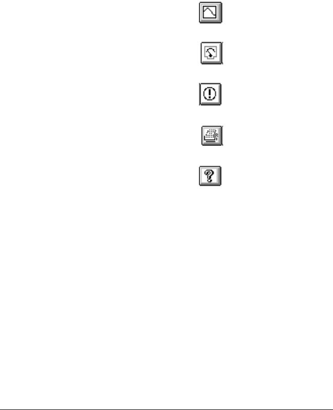
Table 2.2 – Toolbar Icons and Menus
To: |
Use this icon: |
Or this menu command: |
|
|
|
Access the PC Scope. |
|
Drive | PC Scope |
|
|
|
Control the drive. |
|
Drive | Control |
|
|
|
Display the drive’s fault and alarm |
|
Drive | Fault/alarm |
logs. |
|
|
|
|
|
Print a configuration file. |
|
File | Print |
|
|
|
Access the on-line help |
|
Help | Contents |
|
|
|
2.6Exiting the CS3000 Software
To exit the software, choose Exit from the File menu. Exit closes the CS3000 software. If you modified the open configuration, you are prompted to save the changes to a configuration file.
2-10 |
Control and Configuration Software V6.1 |

CHAPTER 3
Configuring the Drive
This chapter describes how to configure a drive.
3.1Selecting a Drive
To create a configuration for a drive while the drive is not connected to the CS3000 software, you must choose a drive type. Communication with the drive is not established, but you can open, save and edit configurations. You can also create Parameter lists using the Parameter Monitor.
For information about establishing communication with a drive, see chapter 8.
To select a drive type, follow these steps:
Step 1. From the Drive menu, choose Select.
The Drive Select dialog box is displayed as shown in figure 3.1.
Figure 3.1 – Drive Select—Disconnected
Step 2. Select the drive type and software version as well as the model number and any options (if supported by the drive). Your choice of a model number determines the default values for U.xxx and H.xxx parameters.
Step 3. Click OK to select the drive type.
If you select a GV3000 (version 5.0 or later) or Liqui-Flo drive, the options box displays the option selections. Selecting RMI results in the .r parameters being listed in the Parameter Monitor and Configuration Editor. You must select the Power Module’s model number as well.
You can establish communication with the drive by selecting Connect or by re-starting the CS3000 software. See chapter 8 for more information.
Configuring the Drive |
3-1 |
3.2Creating a New Configuration
You can create a new drive configuration, which sets the parameter values to their defaults. You assign a name to the configuration file when you save it. See section 3.6 for information about saving configurations.
To create a new configuration:
•From the File menu, choose New, or click  .
.
If a configuration file is already open and has been changed, a dialog box is displayed that asks if you want to save the current configuration file. If you select Yes, the Save As dialog box is displayed before the new configuration file is opened.
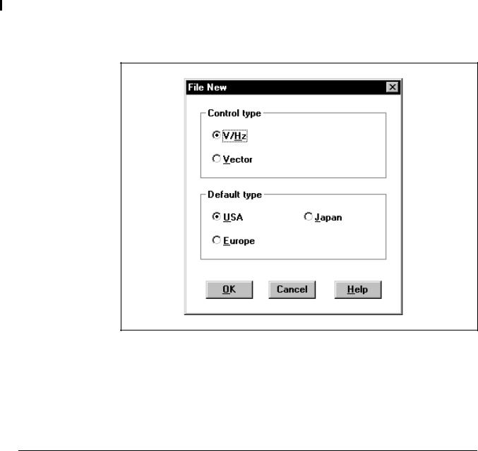
When you create a new GV3000 or Liqui-Flo configuration, the File New dialog box (figure 3.2) is displayed. This lets you select the Vector or Volts/Hertz control (regulation) type and USA, Japan, or Europe as the default type.
After making your selections, select OK to open the new configuration file.
Figure 3.2 – File New Window
When you select the control type, parameters that depend on the control type are changed to their defaults. The control type determines which parameters are displayed. See the appropriate drive instruction manual for more information about the control and default type options.
3-2 |
Control and Configuration Software V6.1 |
3.3Opening a Drive Configuration File
Opening a drive configuration file loads the file from the personal computer to the CS3000 software. Once the configuration file is opened, you can download it to the drive.
To open a configuration file:
Step 1. From the File menu, choose Open or click  .
.
Step 2. If you already have a configuration file open and have made edits to it that have not been saved, you are prompted to save the changes. Make the appropriate selection. See section 3.6 for more information about saving configuration files.
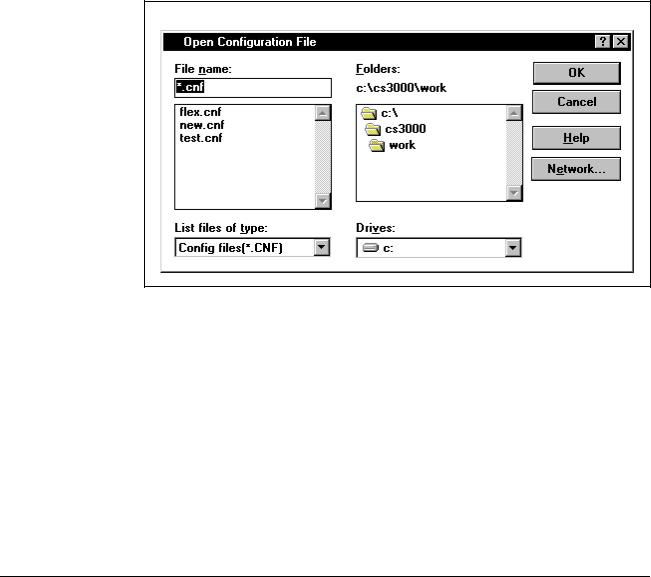
The Open Configuration File dialog box is displayed. An example is shown in figure 3.3.
Figure 3.3 – Open Configuration File Dialog Box
Step 3. The Open Configuration File dialog box defaults to the work directory of the CS3000 software, which was specified during installation. If this is not the correct directory, select the directory where the file is stored.
Step 4. Select the name of the file you want to open. The name of the file should be copied in the File Name box. If not, click on it again.
If the configuration file you want does not have the .CNF extension, it does not show up automatically in the box under File Name. In this case, select *.* in the List Files of Type box to display all of the available files in the File Name list.
Step 5. Open the file by selecting OK. The name of the file you selected now appears in the Opened Configuration field of the main window.
To close the dialog box without selecting a file, select Cancel.
Configuring the Drive |
3-3 |

If the configuration file was: |
Then: |
|
|
not created for the drive currently selected in |
an error message is displayed and the configuration file is |
the CS3000 software |
not opened |
|
Select a configuration file that was created for the selected |
|
drive, or change the selected drive. See section 3.1 for |
|
information about selecting a drive. |
|
|
created for a different version of the currently |
a message box is displayed |
selected drive |
Refer to section 3.4 for more information about opening a |
|
|
|
configuration file for a different version of the same drive. |
|
|
3-4 |
Control and Configuration Software V6.1 |
3.4Opening a Configuration File for a Different Version of the Same Drive
Configuration files include version information about the drive. When you open a configuration file, the CS3000 software compares the configuration file’s drive version to the version of the selected drive. If the versions are different, a message box alerts you of the difference.
.
To: |
Do the following: |
Then: |
|
|
|
not open the file |
Choose No. |
The software returns to the main window without |
|
|
opening the file. |
|
|
|
to copy the configuration file |
Choose Yes. |
A copy of the original configuration file is created. |
to the CS3000 software |
|
Then the CS3000 software checks for differences |
|
|
between the parameters in the copy and the |
|
|
parameters in the currently selected drive. |
|
|
If no parameter differences are found, the CS3000 |
|
|
main window is displayed and the opened |
|
|
configuration is named “UNTITLED.” The original |
|
|
configuration file is not changed. To save the new |
|
|
configuration, see section 3.6. |
|
|
If parameter differences are found, the CS3000 |
|
|
software replaces the parameters in the copied |
|
|
configuration to match the parameters of the |
|
|
currently selected drive version. The Configuration |
|
|
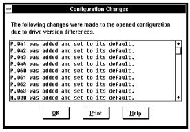
Changes dialog box is displayed, which shows you |
|
|
what changes were made. This dialog box cannot |
|
|
be edited. |
|
|
|
|
|
|
Configuring the Drive |
3-5 |

When parameter difference are found, the CS3000 software makes the following changes to parameters in the configuration file:
If the: |
Then: |
|
|
selected drive is a later version than the drive |
• Parameters are added if they did not exist in the earlier |
for which the configuration file was created |
drive. These parameters are set to default values. |
|
• Parameters that existed in the earlier file might be set |
|
to defaults if some of the options for the parameter did |
|
not exist in the earlier drive version. |
|
|
selected drive is an earlier version than the |
• Parameters are deleted if they do not exist in the |
configuration file |
earlier drive version. |
|
|
parameter range changed between versions |
• A parameter value that is too high is set to the |
of the drive and the parameter is set to a value |
maximum allowed for the selected drive. |
that is out of range for the selected drive |
• A parameter value that is too low is set to the minimum |
|
|
|
value allowed for the selected drive. |
|
|
From the Configuration Changes dialog box, you can print the changes, save the changes to a file for reference, or simply review the changes and return to the main window.
To: |
Do the following: |
|
|
|
|
review the changes |
Use the scroll bar to view the list |
|
|
|
|
print the changes |
Choose Print. |
|
|
The standard Windows Print dialog box is |
|
|
displayed |
|
|
|
|
save the changes to a file that can |
Step 1. Choose Print. |
|
be viewed by an editor such as |
Step 2. Select the Print to File checkbox. |
|
Windows Notepad |
||
|
||
|
Step 3. Choose OK. |
|
|
The Print Configuration Changes to |
|
|
File dialog box is displayed, which is |
|
|
the same as the Save dialog box. |
|
|
Step 4. Specify a directory, file name, and |
|
|
extension. |
|
|
Step 5. Choose OK. |
|
|
|
|
return to the main window from |
Choose OK. |
|
the Configuration Changes dialog |
When you return to the main window, the |
|
box |
||
opened configuration is shown as |
||
|
||
|
“UNTITLED.” The original configuration file is |
|
|
not changed. To save the new configuration, |
|
|
see section 3.6. |
|
|
|
3-6 |
Control and Configuration Software V6.1 |
Loading...