


 Loading...
ut
M C
M C
M C
M 9

The information in this user manual is subject to change without notice.
DANGER
ONLY QUALIFIED ELECTRICAL PERSONNEL WHO ARE FAMILIAR WITH THE CONSTRUCTION AND OPERATION OF THIS EQUIPMENT AND THE HAZARDS INVOLVED SHOULD INSTALL, ADJUST, OPERATE, AND/OR SERVICE THIS EQUIPMENT. READ AND UNDERSTAND THIS MANUAL AND OTHER APPLICABLE MANUALS IN THEIR ENTIRETY BEFORE PROCEEDING. FAILURE TO OBSERVE THIS PRECAUTION COULD RESULT IN SEVERE BODILY INJURY OR LOSS OF LIFE.
DANGER
THE USER IS RESPONSIBLE FOR CONFORMING WITH ALL APPLICABLE LOCAL, NATIONAL, AND INTERNATIONAL CODES. WIRING PRACTICES, GROUNDING, DISCONNECTS, AND OVER CURRENT PROTECTION ARE OF PARTICULAR IMPORTANCE. FAILURE TO OBSERVE THIS PRECAUTION COULD RESULT IN SEVERE BODILY INJURY OR LOSS OF LIFE.
WARNING
THE USER MUST PROVIDE AN EXTERNAL, HARDWIRED EMERGENCY STOP CIRCUIT OUTSIDE THE CONTROLLER CIRCUITRY. THIS CIRCUIT MUST DISABLE THE SYSTEM IN CASE OF IMPROPER OPERATION. UNCONTROLLED MACHINE OPERATION MAY RESULT IF THIS PROCEDURE IS NOT FOLLOWED. FAILURE TO OBSERVE THIS PRECAUTION COULD RESULT IN BODILY INJURY.
WARNING
INSERTING OR REMOVING A MODULE MAY RESULT IN UNEXPECTED MACHINE MOTION. POWER TO THE MACHINE SHOULD BE TURNED OFF BEFORE INSERTING OR REMOVING THE MODULE. FAILURE TO OBSERVE THESE PRECAUTIONS COULD RESULT IN BODILY INJURY.
CAUTION: This module contains static1sensitive components. Careless handling can cause severe damage. Do not touch the connectors or the back of the module. When not in use, the module should be stored in an anti1static bag. The plastic cover should not be removed. Failure to observe these precautions could result in damage to or destruction of the equipment.
A1B, Allen1Bradley, AutoMax, Data Highway Plus, PanelView, PLC, PLC15, RediPANEL, Reliance, and ReSource are trademarks of Rockwell Automation.
Multibus and Intel are a trademarks of Intel Corporation. Motorola is a registered trademark of Motorola Corp.
Phoenix and Combicon are registered trademarks of Phoenix Contact Ltd.
Excel, Plug and Play, and Windows 95 are registered trademarks of Microsoft Corp.
PREFACE
This section describes the purpose, intended audience, and scope of this manual. Some terminology used in this manual is also discussed.
Purpose of This Manual
This manual is intended to help you:
Dinstall, configure, and maintain the AutoMax PC 000, including the AutoMax PC 000 Packaged Version
Dplan, design, install, and maintain the AutoMax DCS2NET network and the Allen2Bradley Remote I/O link
Dunderstand how to structure your application programs
Dwrite application programs for initializing the AutoMax PC 000 remote I/O scanner interface and block transferring data to Allen2Bradley remote block2transfer modules
Intended Audience
This manual assumes an understanding of the:
DAutoMax DCS processors
DAutoMax Programming Executive software
DAllen2Bradley Remote I/O
Dcontrol system application and theory
Terminology Used in This Manual
This term: |
Refers to the: |
|
|
PC 000 |
AutoMax PC 000 Processor card or |
|
the AutoMax PC 000 Packaged Ver2 |
|
sion |
|
|
AutoMax PC 000 Processor card |
M/N C 0 |
|
|
AutoMax PC 000 Serial card |
M/N C |
|
|
AutoMax PC 000 Packaged Version |
M/N C 0 |
|
AutoMax PC 000 Processor card and |
|
Serial card installed in an industrial2 |
|
ized chassis. |
|
|
For definitions of more terms, refer to the Glossary located in the back of this manual.
P2i
Overview of This anual
This manual is divided into seven sections, identified by a numbered tab. The sections group related chapters according to the type of information being conveyed and follow the sequence of the life1cycle for a control system.
Tab Number: |
Section: |
Chapters It |
Description: |
|
|
Contains: |
|
|
|
|
|
1 |
Introduction |
chapter 1, About the |
Provides an overview of |
|
|
AutoMax PC3000 |
the AutoMax PC3000 |
|
|
|
and its capabilities. |
|
|
|
|
|
|
chapter 2, Getting |
Provides a flowchart of |
|
|
Started |
the tasks you need to |
|
|
|
accomplish to get the |
|
|
|
AutoMax PC3000 |
|
|
|
installed and running |
|
|
|
programs. |
|
|
|
|
2 |
Design |
chapter 3, Designing |
Provides information |
|
|
an AutoMax |
about choosing the |
|
|
DCS1NET network |
appropriate network |
|
|
|
media and planning the |
|
|
|
network design |
|
|
|
accordingly. |
|
|
|
|
|
|
chapter 4, Designing |
Provides an overview of |
|
|
Control Systems That |
the Allen1Bradley remote |
|
|
Use the Allen1Bradley |
I/O addressing and |
|
|
Remote I/O Link |
recommendations for |
|
|
|
link design. |
|
|
|
|
P1ii
Tab Number: |
Section: |
Chapters It |
Description: |
|
|
Contains: |
|
|
|
|
|
3 |
Installation |
chapter 5, Installing |
Provides the procedures |
|
|
the AutoMax PC3000 |
for installing the |
|
|
Processor and Serial |
Processor and Serial |
|
|
Cards |
cards into a PC chassis. |
|
|
|
|
|
|
chapter 6, Installing |
Provides the procedures |
|
|
the AutoMax PC3000 |
for mounting the chassis |
|
|
Packaged Version |
and connecting |
|
|
|
incoming power and |
|
|
|
ground lines. |
|
|
|
|
|
|
chapter 7, Installing |
Provides information to |
|
|
the AutoMax Coaxial |
help you install and test |
|
|
DCS5NET Network |
the DCS5NET network |
|
|
|
using coaxial cable. |
|
|
|
|
|
|
chapter 8, Installing |
Provides information to |
|
|
an AutoMax |
help you install and test |
|
|
Fiber5Optic DCS5NET |
the DCS5NET network |
|
|
Network |
using fiber5optic cable. |
|
|
|
|
|
|
chapter 9, |
Provides the procedures |
|
|
Connecting an |
for connecting the |
|
|
Allen5Bradley Remote |
Allen5Bradley remote I/O |
|
|
I/O Link |
link to the PC3000 |
|
|
|
Processor card. |
|
|
|
|
|
|
chapter 10, |
Provides information |
|
|
Connecting a |
about how to connect a |
|
|
Programming Device |
programming device |
|
|
to the AutoMax |
that is running the |
|
|
PC3000 |
AutoMax Programming |
|
|
|
Executive software to the |
|
|
|
PC3000. |
|
|
|
|
|
|
chapter 11, |
Provides information |
|
|
Connecting Devices |
about how to connect |
|
|
to Port A of the Serial |
modems, PCs, and |
|
|
Card |
other DCE devices to |
|
|
|
Port A on the AutoMax |
|
|
|
PC3000. |
|
|
|
|
4 |
Configuration |
chapter 12, |
Provides the procedures |
|
|
Configuring the |
for setting up and |
|
|
AutoMax PC3000 |
configuring the PC3000, |
|
|
|
including setting the |
|
|
|
DCS5NET drop number |
|
|
|
and depth and the |
|
|
|
Processor tick rate. |
|
|
|
|
|
|
chapter 13, |
Provides the procedures |
|
|
Configuring the |
for configuring variables |
|
|
AutoMax |
for the remote rack |
|
|
Allen5Bradley PC3000 |
inputs and outputs and |
|
|
Scanner |
the remote I/O scanner. |
|
|
|
|
|
|
chapter 14, |
Explains the theory of |
|
|
Configuring and |
block5data transfers to |
|
|
Programming the |
remote I/O and provides |
|
|
Block Data Transfers |
information about setting |
|
|
to Allen5Bradley I/O |
up and programming |
|
|
Modules |
them. |
|
|
|
|
P5iii
Tab Number: |
Section: |
Chapters It |
Description: |
|
|
Contains: |
|
|
|
|
|
5 |
Programming |
chapter 15, AutoMax |
Provides introductory |
|
and Operation |
Programming Basics |
information about the |
|
|
|
available programming |
|
|
|
languages and the |
|
|
|
foundation structures |
|
|
|
needed to create |
|
|
|
programs. |
|
|
|
|
|
|
chapter 16, Initializing |
Provides information |
|
|
the AutoMax PC3000 |
about writing a program |
|
|
A2B Remote I/O |
to initialize the remote |
|
|
Scanner |
I/O scanner. The |
|
|
|
scanner must be |
|
|
|
initialized before it can |
|
|
|
control remote I/O racks. |
|
|
|
|
|
|
chapter 17, |
Provides information |
|
|
Communicating with |
about the PC3000 |
|
|
the AutoMax PC3000 |
Application Interface. |
|
|
Over the ISA Bus |
|
|
|
|
|
|
|
chapter 18, |
Provides information |
|
|
Monitoring the |
about the variables you |
|
|
AutoMax PC3000 |
need to monitor |
|
|
|
periodically via your |
|
|
|
application programs. |
|
|
|
|
6 |
Troubleshooting |
chapter 19, |
Provides tips and |
|
and Maintenance |
Troubleshooting the |
information to help you |
|
|
AutoMax PC3000 |
determine and fix |
|
|
|
operational issues. |
|
|
|
|
|
|
chapter 20, |
Provides procedures for |
|
|
Maintaining the |
replacing the lithium |
|
|
AutoMax PC3000 |
battery and the PC3000 |
|
|
|
Processor and Serial |
|
|
|
cards. |
|
|
|
|
|
|
chapter 21, |
Provides |
|
|
Maintaining the |
recommendations to |
|
|
DCS2NET Network |
help you maintain the |
|
|
|
coaxial and fiber2optic |
|
|
|
cable systems. |
|
|
|
|
P2iv
Tab Number: |
Section: |
Chapters It |
Description: |
|
|
Contains: |
|
|
|
|
|
7 |
Reference |
Appendix A, |
Lists the technical data |
|
|
Specifications |
for the PC3000 |
|
|
|
Processor and Serial |
|
|
|
cards and the PC3000 |
|
|
|
Packaged Version. |
|
|
|
|
|
|
Appendix B, |
Lists guidelines to help |
|
|
Recommendations |
you build PC3000 |
|
|
for building |
systems that comply |
|
|
CE<Compliant |
with the European Union |
|
|
Systems |
Directives 89/336/EEC, |
|
|
|
Electromagnetic |
|
|
|
Compatibility (EMC), |
|
|
|
and 73/23/EEC Low |
|
|
|
Voltage requirements. |
|
|
|
|
|
|
Appendix C, Cable |
Provides part lists for the |
|
|
Reference |
DCS<NET coaxial and |
|
|
|
fiber optic cable systems |
|
|
|
and serial cable pin |
|
|
|
assignments. |
|
|
|
|
|
|
Appendix D, Register |
Lists the PC3000 |
|
|
Assignment Map |
registers and their use. |
|
|
|
|
|
|
Appendix E, |
Lists the part numbers |
|
|
Replacement Parts |
and vendors of the |
|
|
List |
replaceable parts for the |
|
|
|
PC3000. |
|
|
|
|
|
|
Appendix F, Using the |
Explains how to use the |
|
|
Sample AutoMax |
sample configurations |
|
|
Configurations and |
and tasks for the |
|
|
Programs |
AutoMax PC3000, which |
|
|
|
are included on the |
|
|
|
AutoMax Programming |
|
|
|
Executive V4.1A |
|
|
|
application disk. You can |
|
|
|
copy and customize |
|
|
|
these samples for your |
|
|
|
AutoMax PC3000 |
|
|
|
application. They are |
|
|
|
intended to provide you |
|
|
|
with only a starting point |
|
|
|
as you create logic |
|
|
|
customized for your |
|
|
|
application. |
|
|
|
|
|
|
Appendix G, |
Provides examples of |
|
|
Examples of Remote |
Remote I/O scanner |
|
|
I/O Programs |
initialization and |
|
|
|
block<transfer programs. |
|
|
|
|
|
|
Appendix H, Glossary |
Lists terms used in this |
|
|
|
manual that may be |
|
|
|
unfamiliar to you. |
|
|
|
|
|
|
Index |
Points you to the |
|
|
|
location of the |
|
|
|
information you are |
|
|
|
looking for. |
|
|
|
|
P<v
For More Information
Refer to these manuals as needed for more information:
DAutoMax Programming Executive Software manual for version 4.1A or later
DAutoMax programming language reference manuals
DAutoMax Network Interface instruction manual
P"vi
Table of Contents
1.0 About the AutoMax PC3000 . . . . . . . . . . . . . . . . . . . . . . . . . . . . . . . . . 1,1
1.1 How the AutoMax PC3000 Fits into Your Application . . . . . . . . . . 191 1.2 About the AutoMax PC3000 Processor Card . . . . . . . . . . . . . . . . 193 1.2.1 About the PC3000 Processor Functionality . . . . . . . . . . . . 195 1.2.2 About the A9B Remote I/O Functionality . . . . . . . . . . . . . . . 195 About How the Scanner Module Transfers Discrete Data 195 About How the Scanner Module Transfers Block Data . . . 196 1.2.3 About the AutoMax DCS9NET Network Functionality . . . . 196
1.3 About the AutoMax PC3000 Serial Card . . . . . . . . . . . . . . . . . . . . 196 1.4 About the AutoMax PC3000 Packaged Version . . . . . . . . . . . . . . 197 1.5 Related Hardware and Software . . . . . . . . . . . . . . . . . . . . . . . . . . . 198 1.6 What to Do Next . . . . . . . . . . . . . . . . . . . . . . . . . . . . . . . . . . . . . . . . . 199
2.0 Getting Started . . . . . . . . . . . . . . . . . . . . . . . . . . . . . . . . . . . . . . . . . . . . . 2,1
2.1 Overview of the Tasks Required to Install and Configure the AutoMax PC3000 . . . . . . . . . . . . . . . . . . . . . . . . . . . . . . . . . . . . . . . . 292
2.2 Overview of the Tasks Required to Program the
AutoMax PC3000 . . . . . . . . . . . . . . . . . . . . . . . . . . . . . . . . . . . . . . . . 293 2.2.1 Using the AutoMax Programming Executive Software
Offline . . . . . . . . . . . . . . . . . . . . . . . . . . . . . . . . . . . . . . . . . . . . 294 2.2.2 Using the AutoMax Programming Executive Software
Online . . . . . . . . . . . . . . . . . . . . . . . . . . . . . . . . . . . . . . . . . . . . 295 2.3 Finding the Information You Need When You Are New to
AutoMax . . . . . . . . . . . . . . . . . . . . . . . . . . . . . . . . . . . . . . . . . . . . . . . . 296 2.4 Finding the Information You Need When You Are New to
Allen9Bradley Remote I/O . . . . . . . . . . . . . . . . . . . . . . . . . . . . . . . . . 296 2.5 Overview of the Tasks Required to Configure and Run the
Remote I/O Scanner Interface . . . . . . . . . . . . . . . . . . . . . . . . . . . . . 296 2.6 What to Do Next . . . . . . . . . . . . . . . . . . . . . . . . . . . . . . . . . . . . . . . . . 297
3.0 Designing an AutoMax DCS,NET Network . . . . . . . . . . . . . . . . . . . . 3,1
3.1 About the AutoMax DCS9NET Network . . . . . . . . . . . . . . . . . . . . . 391 3.2 Choosing the DCS9NET Network Media . . . . . . . . . . . . . . . . . . . . 395 3.3 Designing a Coaxial Network . . . . . . . . . . . . . . . . . . . . . . . . . . . . . . 397 3.3.1 AutoMax Network Coaxial Cable System Components . . 397 3.3.2 Selecting the Cable Type . . . . . . . . . . . . . . . . . . . . . . . . . . . . 399 3.3.3 Planning for Installation . . . . . . . . . . . . . . . . . . . . . . . . . . . . . 3910
3.3.4 Cable System Protection and Isolation
Recommendations . . . . . . . . . . . . . . . . . . . . . . . . . . . . . . . . . 3911 3.4 Designing a Fiber9Optic Cable Network . . . . . . . . . . . . . . . . . . . . . 3913 3.4.1 DCS9NET Fiber9Optic Network System Components . . . . 3916 3.4.2 Planning for Installation . . . . . . . . . . . . . . . . . . . . . . . . . . . . . 3919 3.5 Calculating the Data Update Rate . . . . . . . . . . . . . . . . . . . . . . . . . . 3920
3.6 What to Do Next . . . . . . . . . . . . . . . . . . . . . . . . . . . . . . . . . . . . . . . . . 3920
4.0Designing Control Systems That Use the Allen,Bradley
Remote I/O Link . . . . . . . . . . . . . . . . . . . . . . . . . . . . . . . . . . . . . . . . . . . . 4,1
4.1 Components of an Allen9Bradley Remote I/O System . . . . . . . . . 492 4.2 Dividing I/O into Racks . . . . . . . . . . . . . . . . . . . . . . . . . . . . . . . . . . . 493 4.2.1 Allen9Bradley's I/O Addressing Concept . . . . . . . . . . . . . . . 493 4.2.2 Choosing an Addressing Method . . . . . . . . . . . . . . . . . . . . 495 4.2.3 Addressing Block9Transfer Modules . . . . . . . . . . . . . . . . . . 499
I
|
4.2.4 Determining Your Remote I/O Racks . . . . . . . . . . . . . . . . . . |
4;10 |
|
|
4.2.5 Addressing Summary . . . . . . . . . . . . . . . . . . . . . . . . . . . . . . . |
4;10 |
|
4.3 |
Designing a Remote I/O Link . . . . . . . . . . . . . . . . . . . . . . . . . . . . . . |
4;11 |
|
|
4.3.1 Deciding on a Data Communication Rate . . . . . . . . . . . . . |
4;12 |
|
|
4.3.2 Determining the Required Cable Lengths and |
|
|
|
Terminating Resistors . . . . . . . . . . . . . . . . . . . . . . . . . . . . . . |
4;12 |
|
4.4 |
Determining Remote I/O Scan Times . . . . . . . . . . . . . . . . . . . . . . . |
4;13 |
|
|
4.4.1 Determining the Effect on the Remote I/O Scan Time |
|
|
|
by the Data Communication Rate . . . . . . . . . . . . . . . . . . . . |
4;14 |
|
|
4.4.2 Determining the Effect on the Remote I/O Scan Time |
|
|
|
by Block;Transfer Requests . . . . . . . . . . . . . . . . . . . . . . . . . . |
4;14 |
|
|
4.4.3 Calculating the Worst;Case Remote I/O Scan Time . . . . . |
4;15 |
|
4.5 |
Optimizing System Performance . . . . . . . . . . . . . . . . . . . . . . . . . . . |
4;15 |
|
4.6 |
Allen;Bradley Remote I/O Installation Considerations . . . . . . . . . |
4;16 |
|
|
4.6.1 About Remote I/O System Wiring . . . . . . . . . . . . . . . . . . . . |
4;17 |
|
|
4.6.1.1 |
Categorizing Conductors . . . . . . . . . . . . . . . . . . . . |
4;17 |
|
4.6.1.2 |
Routing Conductors . . . . . . . . . . . . . . . . . . . . . . . . . |
4;17 |
|
4.6.2 About Remote I/O System Grounding . . . . . . . . . . . . . . . . . |
4;18 |
|
|
4.6.3 Recommended Switch Settings . . . . . . . . . . . . . . . . . . . . . . |
4;18 |
|
4.7 |
What to Do Next . . . . . . . . . . . . . . . . . . . . . . . . . . . . . . . . . . . . . . . . . |
4;19 |
|
5.0Installing the AutoMax PC3000 Processor and Serial Cards . . . 5 1
5.1 Handling the Cards . . . . . . . . . . . . . . . . . . . . . . . . . . . . . . . . . . . . . . 5;1 5.2 Installing the AutoMax PC3000 Processor Card . . . . . . . . . . . . . . 5;2 5.2.1 Preparing the Computer . . . . . . . . . . . . . . . . . . . . . . . . . . . . 5;2 5.2.2 Installing the AutoMax PC3000 Processor Card . . . . . . . . 5;2 5.3 Installing the AutoMax PC3000 Driver . . . . . . . . . . . . . . . . . . . . . . . 5;4
5.4 Configuring the AutoMax PC3000 for Use with the AutoMax Programming Executive Software . . . . . . . . . . . . . . . . . . . . . . . . . . 5;4 5.4.1 Adding the AutoMax PC3000 Processor to the
Device Manager . . . . . . . . . . . . . . . . . . . . . . . . . . . . . . . . . . . 5;4 5.4.2 Adding the PC3000 Processor Card's Address to the
SYSTEM.INI File . . . . . . . . . . . . . . . . . . . . . . . . . . . . . . . . . . . 5;5 5.4.3 Adding the PC3000 Processor Card's Address to the
CONFIG.SYS File . . . . . . . . . . . . . . . . . . . . . . . . . . . . . . . . . . 5;6 5.5 Installing the Optional AutoMax PC3000 Serial Card . . . . . . . . . . 5;6 5.5.1 Preparing the Computer . . . . . . . . . . . . . . . . . . . . . . . . . . . . 5;7
5.5.2Configuring Port A for RS;232 or RS;422 Communication 5;7
5.5.3Configuring the AutoMax PC3000 Serial Card for Use
in a PC Chassis . . . . . . . . . . . . . . . . . . . . . . . . . . . . . . . . . . . . 5;8 5.5.4 Installing and Connecting the Card . . . . . . . . . . . . . . . . . . . 5;8 5.6 Wiring Considerations . . . . . . . . . . . . . . . . . . . . . . . . . . . . . . . . . . . . 5;9
5.7 Manually Configuring the Processor Card When Device Conflicts Are Present . . . . . . . . . . . . . . . . . . . . . . . . . . . . . . . . . . . . . . . . . . . . . 5;10
5.8 Installing Multiple PC3000 Processor Cards in a PC . . . . . . . . . . 5;12 5.8.1 Accessing the Device Manager List . . . . . . . . . . . . . . . . . . . 5;12 5.8.2 Adding the Processor Card . . . . . . . . . . . . . . . . . . . . . . . . . . 5;12 5.8.3 Adding the PC3000 Processor Card's Address to the
SYSTEM.INI File . . . . . . . . . . . . . . . . . . . . . . . . . . . . . . . . . . . 5;13 5.8.4 Adding the PC3000 Processor Card's Address to the
CONFIG.SYS File . . . . . . . . . . . . . . . . . . . . . . . . . . . . . . . . . . 5;14 5.9 What to Do Next . . . . . . . . . . . . . . . . . . . . . . . . . . . . . . . . . . . . . . . . . 5;14
II
6.0 Installing the AutoMax PC3000 Packaged Version . . . . . . . . . . . . |
601 |
|
6.1 |
Planning for Installation . . . . . . . . . . . . . . . . . . . . . . . . . . . . . . . . . . . |
691 |
6.2 |
Wiring Considerations . . . . . . . . . . . . . . . . . . . . . . . . . . . . . . . . . . . . |
692 |
6.3 |
Mounting the AutoMax PC3000 Packaged Version . . . . . . . . . . . |
692 |
6.4 |
Grounding the AutoMax PC3000 Packaged Version . . . . . . . . . . |
693 |
6.5 |
Connecting Power . . . . . . . . . . . . . . . . . . . . . . . . . . . . . . . . . . . . . . . |
693 |
6.6 |
Turning on the AutoMax PC3000 . . . . . . . . . . . . . . . . . . . . . . . . . . . |
693 |
6.7 |
Installation Considerations When Installing a Microprocessor |
|
|
Card in the PC3000 Industrialized Chassis . . . . . . . . . . . . . . . . . . |
694 |
6.8 |
What to Do Next . . . . . . . . . . . . . . . . . . . . . . . . . . . . . . . . . . . . . . . . . |
695 |
7.0 Installing an AutoMax Coaxial DCS0NET Network . . . . . . . . . . . . . 701
7.1 Constructing a Coaxial Cable System . . . . . . . . . . . . . . . . . . . . . . 791 7.2 Inspecting and Testing the Cable . . . . . . . . . . . . . . . . . . . . . . . . . . 791 7.3 Pulling the Cable . . . . . . . . . . . . . . . . . . . . . . . . . . . . . . . . . . . . . . . . 792 7.4 Terminating the Cable . . . . . . . . . . . . . . . . . . . . . . . . . . . . . . . . . . . . 792 7.4.1 Terminating RG959/U Cable . . . . . . . . . . . . . . . . . . . . . . . . . 793 7.4.2 Terminating RG911/U Cable . . . . . . . . . . . . . . . . . . . . . . . . . 797
7.5 Testing Cable Segments . . . . . . . . . . . . . . . . . . . . . . . . . . . . . . . . . . 7911 7.6 Constructing Long Cable Segments . . . . . . . . . . . . . . . . . . . . . . . . 7912 7.7 What to Do Next . . . . . . . . . . . . . . . . . . . . . . . . . . . . . . . . . . . . . . . . . 7913
8.0 Installing an AutoMax Fiber0Optic DCS0NET Network . . . . . . . . . 801
8.1 Installing the Stand9Alone Transceiver . . . . . . . . . . . . . . . . . . . . . . 892 8.2 Installing the Rack/Power Supply and Rack9Mounted
Transceivers . . . . . . . . . . . . . . . . . . . . . . . . . . . . . . . . . . . . . . . . . . . . 893 8.3 Installing the Fiber9Optic Cable . . . . . . . . . . . . . . . . . . . . . . . . . . . . 896 8.4 Attaching the Fiber9Optic Connectors . . . . . . . . . . . . . . . . . . . . . . 896 8.5 Connecting a Fiber9Optic Cable Between a Stand9Alone
Transceiver and a Rack9Mounted Transceiver . . . . . . . . . . . . . . . . 897 8.6 What to Do Next . . . . . . . . . . . . . . . . . . . . . . . . . . . . . . . . . . . . . . . . . 898
9.0 Connecting an Allen0Bradley Remote I/O Link . . . . . . . . . . . . . . . . |
901 |
|
9.1 |
Connecting the Remote I/O Link to the PC3000 |
|
|
Processor Card . . . . . . . . . . . . . . . . . . . . . . . . . . . . . . . . . . . . . . . . . . |
991 |
9.2 |
What to Do Next . . . . . . . . . . . . . . . . . . . . . . . . . . . . . . . . . . . . . . . . . |
992 |
10.0 Connecting a Programming Device to the AutoMax PC3000 . . . |
1001 |
|
10.1 |
Overview of the Connection Methods . . . . . . . . . . . . . . . . . . . . . . . |
1091 |
10.2 |
Connecting to the AutoMax PC3000 Via the ISA Bus . . . . . . . . . |
1092 |
10.3 |
Connecting to the AutoMax PC3000 Via Port B of the |
|
|
Serial Card . . . . . . . . . . . . . . . . . . . . . . . . . . . . . . . . . . . . . . . . . . . . . . |
1093 |
|
10.3.1 Using the Correct Cable . . . . . . . . . . . . . . . . . . . . . . . . . . . . |
1093 |
|
10.3.2 Setting the Communication Parameters . . . . . . . . . . . . . . . |
1094 |
10.4 |
Connecting a Modem to the AutoMax PC3000 Via Port B |
|
|
of the Serial Card . . . . . . . . . . . . . . . . . . . . . . . . . . . . . . . . . . . . . . . |
1094 |
|
10.4.1 Setting Up the Modem That Is Connected to the |
|
|
AutoMax PC3000 . . . . . . . . . . . . . . . . . . . . . . . . . . . . . . . . . . |
1095 |
|
10.4.2 Setting Up the Programming Device's Modem . . . . . . . . . |
1095 |
10.5 |
Connecting to an AutoMax PC3000 Processor |
|
|
Via the DCS9NET Network . . . . . . . . . . . . . . . . . . . . . . . . . . . . . . . . |
1095 |
10.6 |
What to Do Next . . . . . . . . . . . . . . . . . . . . . . . . . . . . . . . . . . . . . . . . . |
1096 |
III
11.0 Connecting Devices to the AutoMax PC3000 Serial Card Ports . |
11&1 |
||
11.1 |
Connecting Devices to Port A . . . . . . . |
. . . . . . . . . . . . . . . . . . . . . . |
1161 |
|
11.1.1 Selecting RS6232 or RS6422 Interface . . . . . . . . . . . . . . . . . |
1161 |
|
|
11.1.2 Using the Correct Cable . . . . . . |
. . . . . . . . . . . . . . . . . . . . . . |
1162 |
11.2 |
Connecting Devices to Port B . . . . . . . |
. . . . . . . . . . . . . . . . . . . . . . |
1166 |
|
11.2.1 Making Port B Available . . . . . . . |
. . . . . . . . . . . . . . . . . . . . . . |
1166 |
|
11.2.2 Using the Correct Cable . . . . . . |
. . . . . . . . . . . . . . . . . . . . . . |
1167 |
11.3 |
Accessing the Serial Card Ports . . . . . |
. . . . . . . . . . . . . . . . . . . . . . |
11611 |
11.4 |
What to Do Next |
|
|
12.0 Configuring the AutoMax PC3000 . . . . . . |
. . . . . . . . . . . . . . . . . . . . C. 12&1 |
||
12.1 Adding an AutoMax PC3000 . . . . . . . . |
. . . . . . . . . . . . . . . . . . . . . . |
1261 |
|
12.2 |
Converting an Existing Rack into an AutoMax PC3000 . . . . . . . . |
1263 |
|
12.3 |
Specifying the DCS6NET Drop Number and Drop Depth . . . . . . |
1263 |
|
|
12.3.1 Setting the DCS6NET Network Drop Number and |
|
|
|
Depth While Offline . . . . . . . . . . . |
. . . . . . . . . . . . . . . . . . . . . . |
1264 |
|
12.3.2 Setting the Physical Drop Number Using the |
|
|
|
Change Drop Command While Online . . . . . . . . . . . . . . . . |
1264 |
|
|
12.3.3 Setting the Drop Depth by Using Program Logic . . . . . . . |
1265 |
|
12.4 |
Specifying the AutoMax PC3000 CPU Tick Rate . . . . . . . . . . . . . . |
1266 |
|
12.5 |
Assigning a Name to the AutoMax PC3000 Installed in a |
|
|
|
PC Chassis . . . . . . . . . . . . . . . . . . . . . . . |
. . . . . . . . . . . . . . . . . . . . . . |
1266 |
12.6 Using the AutoMax PC3000 CPU Common Memory Variables . 1267 |
|||
12.7 |
Using the DCS6NET Network Register Variables . . . . . . . . . . . . . |
1267 |
|
12.8 |
Configuring the AutoMax PC3000 as a Passive6Listening |
|
|
|
DCS6NET Network Drop . . . . . . . . . . . . |
. . . . . . . . . . . . . . . . . . . . . . |
1268 |
12.9 |
What to Do Next . . . . . . . . . . . . . . . . . . . . |
. . . . . . . . . . . . . . . . . . . . . |
1269 |
13.0 Configuring the AutoMax PC3000 A&B Remote I/O Scanner . . . . |
13&1 |
||
13.1 |
About Configuring the AutoMax PC3000 Scanner Interface . . . . |
1361 |
|
13.2 |
Configuring the Remote I/O Racks . . . . |
. . . . . . . . . . . . . . . . . . . . . |
1362 |
|
13.2.1 Assigning Variable Names to the Inputs and Outputs in the |
||
|
Remote Racks . . . . . . . . . . . . . . . . |
. . . . . . . . . . . . . . . . . . . . . |
1362 |
|
13.2.2 Assigning Variable Names to Remote I/O Rack Status and |
||
|
Control Registers . . . . . . . . . . . . . |
. . . . . . . . . . . . . . . . . . . . . |
1363 |
13.3 |
Configuring the I/O Scanner by Assigning Variable Names to the |
||
|
Scanner Setup and Status Registers . . |
. . . . . . . . . . . . . . . . . . . . . |
1364 |
13.4 |
AutoMax PC3000 Scanner Configuration Example . . . . . . . . . . . |
1366 |
|
13.5 |
What to Do Next . . . . . . . . . . . . . . . . . . . . |
. . . . . . . . . . . . . . . . . . . . . |
1367 |
14.0 Configuring and Programming Block Data Transfers to A&B |
|
||
I/O Modules . . . . . . . . . . . . . . . . . . . . . . . . . . |
C. . . . . . . . . . . . . . . . . . . . . |
14&1 |
|
14.1 |
About Block6Transfers . . . . . . . . . . . . . . . |
. . . . . . . . . . . . . . . . . . . . . |
1461 |
|
14.1.1 About Block6Transfer Read and Write Requests . . . . . . . . |
1461 |
|
|
14.1.2 About Continuous and Non6Continuous Block6Transfer |
|
|
|
Requests . . . . . . . . . . . . . . . . . . . . |
. . . . . . . . . . . . . . . . . . . . . |
1463 |
14.2 |
Configuring Block6Transfers . . . . . . . . . . |
. . . . . . . . . . . . . . . . . . . . . |
1464 |
|
14.2.1 Assigning Variable Names to a Block6Transfer Status and |
|
|
|
Request Table . . . . . . . . . . . . . . . . |
. . . . . . . . . . . . . . . . . . . . . |
1464 |
|
14.2.2 Assigning Variable Names to the Block6Transfer |
|
|
|
Data Table Registers . . . . . . . . . . |
. . . . . . . . . . . . . . . . . . . . . |
1465 |
14.3 |
Programming Block6Transfers . . . . . . . . |
. . . . . . . . . . . . . . . . . . . . . |
1466 |
|
14.3.1 Specifying the Location of the Target |
|
|
|
Block6Transfer Module . . . . . . . . . |
. . . . . . . . . . . . . . . . . . . . . |
1467 |
IV
|
|
14.3.2 Specifying a Read or Write Operation . . . |
. . . . . . . . . . . . . . |
14<8 |
|
|
14.3.3 Specifying the Length of a Block<Transfer |
. . . . . . . . . . . . . |
14<8 |
|
|
14.3.4 Specifying the Update Time of the Block<Transfer . . . . . . |
14<8 |
|
|
|
14.3.5 Initiating Block<Transfer Requests to I/O Modules . . . . . . . |
14<9 |
|
|
|
14.3.6 Using the Block<Transfer Data Table . . . . |
. . . . . . . . . . . . . . |
14<9 |
|
14.4 |
Monitoring Block<Transfer Status . . . . . . . . . . . . . |
. . . . . . . . . . . . . . |
14<9 |
|
|
14.4.1 Monitoring the Block<Transfer Error Bit |
|
|
|
|
(Status and Control Word Bit 8) . . . . . . . . |
. . . . . . . . . . . . . . |
14<10 |
|
|
14.4.2 Monitoring the Block<Transfer Complete Bit |
|
|
|
|
(Status and Control Word Bit 9) . . . . . . . . |
. . . . . . . . . . . . . . |
14<10 |
|
|
14.4.3 Block<Transfer Status Bit Summary . . . . . |
. . . . . . . . . . . . . . |
14<11 |
|
14.5 |
What to Do Next . . . . . . . . . . . . . . . . . . . . . . . . . . . |
. . . . . . . . . . . . . . |
14<11 |
15.0 |
Programming Basics . . . . . . . . . . . . . . . . . . . . . . . . . . |
A. . . . . . . . . . . . . |
15'1 |
|
|
15.1 |
Programming Overview . . . . . . . . . . . . . . . . . . . . . |
. . . . . . . . . . . . . . |
15<1 |
|
|
15.1.1 About the Multi<Tasking Operating System . . . . . . . . . . . . |
15<1 |
|
|
|
15.1.2 About User<Scheduled Programs . . . . . . |
. . . . . . . . . . . . . . |
15<2 |
|
|
15.1.3 About Symbolic Programming . . . . . . . . . . |
. . . . . . . . . . . . . |
15<3 |
|
|
15.1.4 About the Available Programming Languages . . . . . . . . . |
15<3 |
|
|
15.2 |
Organizing Your Application Project . . . . . . . . . . . |
. . . . . . . . . . . . . |
15<5 |
|
15.3 |
About the Organization of the AutoMax Programming Executive |
|
|
|
|
Software . . . . . . . . . . . . . . . . . . . . . . . . . . . . . . . . . . . |
. . . . . . . . . . . . . |
15<5 |
|
15.4 |
Configuring I/O . . . . . . . . . . . . . . . . . . . . . . . . . . . . . |
. . . . . . . . . . . . . |
15<6 |
|
15.5 |
Configuring Variables . . . . . . . . . . . . . . . . . . . . . . . |
. . . . . . . . . . . . . |
15<6 |
|
15.6 |
What to Do Next . . . . . . . . . . . . . . . . . . . . . . . . . . . . |
. . . . . . . . . . . . . |
15<6 |
16.0 |
Initializing the AutoMax PC3000 A'B Remote I/O Scanner . . . . . |
16'1 |
||
|
16.1 |
Specifying the Data Communication Rate . . . . . . |
. . . . . . . . . . . . . |
16<1 |
|
16.2 |
Specifying the Remote Racks That Will Be Scanned . . . . . . . . . . |
16<2 |
|
|
16.3 |
Initiating Scanning . . . . . . . . . . . . . . . . . . . . . . . . . . |
. . . . . . . . . . . . . |
16<3 |
|
16.4 |
Placing the Scanner in RUN Mode . . . . . . . . . . . . |
. . . . . . . . . . . . . |
16<3 |
|
16.5 |
What to Do Next . . . . . . . . . . . . . . . . . . . . . . . . . . . . |
. . . . . . . . . . . . . |
16<3 |
17.0 |
Exchanging Data with an AutoMax PC3000 over the ISA Bus . . |
17'1 |
||
|
17.1 |
About the Register Organization of the AutoMax PC3000 |
|
|
|
|
Application Interface . . . . . . . . . . . . . . . . . . . . . . . . |
. . . . . . . . . . . . . |
17<1 |
|
17.2 |
Using the Volatile Variables . . . . . . . . . . . . . . . . . . |
. . . . . . . . . . . . . |
17<1 |
|
17.3 |
Using the Non<Volatile Variables . . . . . . . . . . . . . . |
. . . . . . . . . . . . . |
17<1 |
|
17.4 |
Using the System Information Variables . . . . . . . . |
. . . . . . . . . . . . . |
17<2 |
|
17.5 |
What to Do Next . . . . . . . . . . . . . . . . . . . . . . . . . . . . |
. . . . . . . . . . . . . |
17<2 |
18.0 Monitoring the AutoMax PC3000 . . . . . . . . . . . . . . . . |
. . . . . . . . . . A. . |
18'1 |
||
|
18.1 |
Monitoring the Status of the Battery . . . . . . . . . . . |
. . . . . . . . . . . . . |
18<1 |
|
18.2 |
Monitoring Status . . . . . . . . . . . . . . . . . . . . . . . . . . . |
. . . . . . . . . . . . . |
18<1 |
|
|
18.2.1 Monitoring Scanner Status . . . . . . . . . . . . . |
. . . . . . . . . . . . . |
18<1 |
|
|
18.2.2 Monitoring Remote I/O Link Status . . . . . . |
. . . . . . . . . . . . . |
18<1 |
|
|
18.2.3 Monitoring Rack Status and Error Counters . . . . . . . . . . . |
18<2 |
|
|
18.3 |
Overview of the DCS<NET Interface Register Organization . . . . . |
18<3 |
|
|
|
18.3.1 Using the Registers in the Drop 0 Area . . . |
. . . . . . . . . . . . . |
18<3 |
|
|
18.3.2 Assigning Variables to the Data Exchange |
|
|
|
|
Registers . . . . . . . . . . . . . . . . . . . . . . . . . . . . |
. . . . . . . . . . . . . |
18<8 |
|
18.4 |
Ensuring Network Integrity . . . . . . . . . . . . . . . . . . . |
. . . . . . . . . . . . . |
18<9 |
|
18.5 |
Detecting Partial Network Failure . . . . . . . . . . . . . |
. . . . . . . . . . . . . |
18<10 |
V
18.6 What to Do Next . . . . . . . . . . . . . . . . . . . . . . . . . . . . . . . . . . . . . . . . . 18<10
19.0 Troubleshooting the AutoMax PC3000 . . . . . . . . . . . . . . . . . . . . . . . 19 1
19.1 Interpreting LED Indicators on the AutoMax PC3000
Processor Card . . . . . . . . . . . . . . . . . . . . . . . . . . . . . . . . . . . . . . . . . . 19<1 19.2 Interpreting Error Codes . . . . . . . . . . . . . . . . . . . . . . . . . . . . . . . . . . 19<3 19.2.1 Interpreting CPU Error Codes . . . . . . . . . . . . . . . . . . . . . . . . 19<4
19.2.2 Interpreting DCS<NET Network Error Codes . . . . . . . . . . . 19<17 19.2.3 Interpreting A<B Remote I/O Error Codes . . . . . . . . . . . . . . 19<20 19.3 Handling Remote I/O Rack Errors . . . . . . . . . . . . . . . . . . . . . . . . . . 19<21 19.4 Handling Bus Errors . . . . . . . . . . . . . . . . . . . . . . . . . . . . . . . . . . . . . . 19<22 19.5 Troubleshooting the Serial Ports . . . . . . . . . . . . . . . . . . . . . . . . . . . 19<23 19.6 Receiving Incorrect Data . . . . . . . . . . . . . . . . . . . . . . . . . . . . . . . . . . 19<23 19.7 Resetting the AutoMax PC3000 . . . . . . . . . . . . . . . . . . . . . . . . . . . . 19<24 19.8 Removing the PC3000's Operating System . . . . . . . . . . . . . . . . . . 19<24 19.9 Changing the Remote I/O Data Communication Rate . . . . . . . . . 19<25 19.10 What to Do Next . . . . . . . . . . . . . . . . . . . . . . . . . . . . . . . . . . . . . . . . 19<25
20.0 Maintaining the AutoMax PC3000 . . . . . . . . . . . . . . . . . . . . . . . . . . E. . 20 1
20.1 Handling the Cards . . . . . . . . . . . . . . . . . . . . . . . . . . . . . . . . . . . . . . 20<1 20.2 Replacing the Battery on the AutoMax PC3000 Processor Card 20<1 20.2.1 Removing the AutoMax PC3000 Processor Card . . . . . . . 20<2 20.2.2 Replacing the Battery . . . . . . . . . . . . . . . . . . . . . . . . . . . . . . . 20<2 20.2.3 Re<installing the AutoMax PC3000 Processor Card . . . . . 20<3 20.2.4 Disposing of the Battery . . . . . . . . . . . . . . . . . . . . . . . . . . . . 20<4 20.3 Replacing the AutoMax PC3000 Processor Card . . . . . . . . . . . . . 20<4
20.3.1Removing the Old AutoMax PC3000 Processor Card . . . 20<5
20.3.2Preparing a New AutoMax PC3000 Processor Card for
Installation . . . . . . . . . . . . . . . . . . . . . . . . . . . . . . . . . . . . . . . . 20<6
20.3.3 Installing a New AutoMax PC3000 Processor Card . . . . . 20<6
20.4Removing the old AutoMax PC3000 Processor Card from the Device Manager (Only for a PC3000 Installed in a PC Chassis) 20<7
|
20.4.1 Accessing the Device Manager List . . . . . . . . . . . . . . . . . . . |
20<8 |
|
20.4.2 Removing the Processor Card from the Device Manager |
|
|
List . . . . . . . . . . . . . . . . . . . . . . . . . . . . . . . . . . . . . . . . . . . . . . . |
20<8 |
|
20.4.3 Removing the PC3000 Processor Card's Address from |
|
|
the SYSTEM.INI File . . . . . . . . . . . . . . . . . . . . . . . . . . . . . . . . |
20<9 |
|
20.4.4 Remove the PC3000 Processor Card's Address from |
|
|
the CONFIG.SYS File . . . . . . . . . . . . . . . . . . . . . . . . . . . . . . . |
20<9 |
20.5 |
Replacing the AutoMax PC3000 Serial Card . . . . . . . . . . . . . . . . . |
20<10 |
|
20.5.1 Removing the Old AutoMax PC3000 Serial Card . . . . . . . |
20<10 |
|
20.5.2 Preparing a New AutoMax PC3000 Serial Card for |
|
|
Installation . . . . . . . . . . . . . . . . . . . . . . . . . . . . . . . . . . . . . . . . |
20<11 |
|
20.5.3 Installing a New AutoMax PC3000 Serial Card . . . . . . . . . |
20<11 |
20.6 |
Replacing the AutoMax PC3000 Packaged Version . . . . . . . . . . . |
20<12 |
20.7 |
Replacing the Filter for the AutoMax PC3000 Packaged Version 20<12 |
|
20.8 |
What to Do Next . . . . . . . . . . . . . . . . . . . . . . . . . . . . . . . . . . . . . . . . . |
20<13 |
21.0 Maintaining the DCS NET Network . . . . . . . . . . . . . . . . . . . . . . . . . . E21 1
21.1 Maintaining the Coaxial Cable DCS<NET Network . . . . . . . . . . . . 21<1 21.1.1 Adding a Network Drop . . . . . . . . . . . . . . . . . . . . . . . . . . . . . 21<1 21.1.2 Disconnecting a Network Drop . . . . . . . . . . . . . . . . . . . . . . 21<3 21.1.3 Maintaining the Coaxial Cable System . . . . . . . . . . . . . . . . 21<4
VI
|
21.1.4 Inspecting the Cable System . . . . . . . . . . . . . . . . . . . |
. . . . . 21/4 |
21.2 |
Maintaining the Fiber/Optic DCS/NET Network . . . . . . . . . |
. . . . . 21/4 |
|
21.2.1 Replacing the Stand/Alone Transceiver . . . . . . . . . . |
. . . . . 21/ |
|
21.2.2 Replacing the Rack/Mounted Transceiver . . . . . . . . |
. . . . . 21/ |
|
21.2.3 Replacing the Fiber/Optic Rack and Power Supply |
. . . . . 21/ |
|
21.2.4 Adding a Network Drop . . . . . . . . . . . . . . . . . . . . . . . . |
. . . . . 21/ |
|
21.2. Disconnecting a Network Drop . . . . . . . . . . . . . . . . . |
. . . . . 21/ |
|
21.2. Inspecting the Cable System . . . . . . . . . . . . . . . . . . . |
. . . . . 21/8 |
21.3 |
What to Do Next . . . . . . . . . . . . . . . . . . . . . . . . . . . . . . . . . . . . |
. . . . . 21/8 |
VII
Appendices
Appendix A
Technical Specifications . . . . . . . . . . . . . . . . . . . . . . . . . . . . . . . . . . . . . . A)
Appendix B
Recommendations for Building CE)Compliant Systems . . . . . . . . . . B)
Appendix C
Cable Reference . . . . . . . . . . . . . . . . . . . . . . . . . . . . . . . . . . . . . . . . . . . . C)
Appendix D
Register Assignment Map . . . . . . . . . . . . . . . . . . . . . . . . . . . . . . . . . . . . D)
Appendix E
Replacement Parts . . . . . . . . . . . . . . . . . . . . . . . . . . . . . . . . . . . . . . . . . . E)
Appendix F
Using the Sample AutoMax Configurations and Programs . . . . . . . . F)
Appendix G
Examples of Remote I/O Programs . . . . . . . . . . . . . . . . . . . . . . . . . . . . G)
Appendix H
Glossary of Terms . . . . . . . . . . . . . . . . . . . . . . . . . . . . . . . . . . . . . . . . . . . H)
VIII
List of Figures
Figure 1.1 > The AutoMax PC3000 Networked into Your Application . . . . . . 1>2 Figure 1.2 > AutoMax PC3000 Processor Card . . . . . . . . . . . . . . . . . . . . . . . . . 1>4 Figure 1.3 > Discrete Data Transfer . . . . . . . . . . . . . . . . . . . . . . . . . . . . . . . . . . . 1>5 Figure 1.4 > The AutoMax PC3000 Serial Card . . . . . . . . . . . . . . . . . . . . . . . . . 1>7 Figure 1.5 > AutoMax PC3000 Packaged Version . . . . . . . . . . . . . . . . . . . . . . 1>8 Figure 3.1 > Sample Network . . . . . . . . . . . . . . . . . . . . . . . . . . . . . . . . . . . . . . . . 3>3 Figure 3.2 > Master Initiates Transmission . . . . . . . . . . . . . . . . . . . . . . . . . . . . . 3>4 Figure 3.3 > DCS>NET Fiber>Optic Network . . . . . . . . . . . . . . . . . . . . . . . . . . . 3>6 Figure 3.4 > AutoMax DCS>NET Network Coaxial Cable System . . . . . . . . . 3>7 Figure 3.5 > Representative Racks vs. Network Length . . . . . . . . . . . . . . . . . 3>9 Figure 3.6 > Linking Hubs to Create a Larger Network . . . . . . . . . . . . . . . . . . 3>14 Figure 3.7 > Connecting a Personal Computer to a Stand>Alone
Transceiver . . . . . . . . . . . . . . . . . . . . . . . . . . . . . . . . . . . . . . . . . . . . 3>15 Figure 4.1 > A Typical Remote I/O System . . . . . . . . . . . . . . . . . . . . . . . . . . . . . 4>2 Figure 4.2 > Sample I/O Terminal Memory Mapping . . . . . . . . . . . . . . . . . . . . 4>5 Figure 4.3 > Available I/O Rack Addressing Methods . . . . . . . . . . . . . . . . . . . 4>6 Figure 4.4 > Addressing Example Using 8> and 16>point I/O Modules . . . . . 4>7 Figure 4.5 > Addressing Example Using 32>point I/O Modules . . . . . . . . . . . 4>8 Figure 4.6 > An Example of Efficient I/O Image Table Use . . . . . . . . . . . . . . . 4>9 Figure 4.7 > Daisychain Configuration . . . . . . . . . . . . . . . . . . . . . . . . . . . . . . . . 4>12 Figure 4.8 > System Optimized for Discrete>Data Transfer . . . . . . . . . . . . . . . 4>15 Figure 4.9 > System Optimized for Block>Data Transfer . . . . . . . . . . . . . . . . . 4>16 Figure 4.10 > Recommended Grounding Configuration for Remote I/O
Systems . . . . . . . . . . . . . . . . . . . . . . . . . . . . . . . . . . . . . . . . . . . . . . 4>18 Figure 5.1 > Jumper JP2 Settings . . . . . . . . . . . . . . . . . . . . . . . . . . . . . . . . . . . . 5>3 Figure 5.2 > Configuring Port A for RS>232 or RS>422 . . . . . . . . . . . . . . . . . . . 5>7 Figure 5.3 > Setting Jumpers E3 and E4 . . . . . . . . . . . . . . . . . . . . . . . . . . . . . . 5>8 Figure 5.4 > Connecting the Ribbon Cable . . . . . . . . . . . . . . . . . . . . . . . . . . . . 5>9 Figure 5.5 > List of Device Conflicts . . . . . . . . . . . . . . . . . . . . . . . . . . . . . . . . . . 5>11 Figure 6.1 > Mounting Dimensions for the AutoMax PC3000
Packaged Version . . . . . . . . . . . . . . . . . . . . . . . . . . . . . . . . . . . . . . 6>2 Figure 6.2 > Connecting Incoming Power . . . . . . . . . . . . . . . . . . . . . . . . . . . . . 6>3 Figure 6.3 > Locating the AutoMax PC3000 Power Switch . . . . . . . . . . . . . . . 6>4 Figure 6.4 > Setting Jumpers E3 and E4 . . . . . . . . . . . . . . . . . . . . . . . . . . . . . . 6>5 Figure 7.1 > Slide Ferrule onto RG>59/U Cable . . . . . . . . . . . . . . . . . . . . . . . . . 7>3 Figure 7.2 > RG>59/U (Belden 9259) Cable Stripping Dimensions . . . . . . . . 7>3 Figure 7.3 > Connector Installation Step 3 for RG>59/U Cable . . . . . . . . . . . . 7>4 Figure 7.4 > Connector Installation Step 6 for RG>59/U Cable . . . . . . . . . . . . 7>5 Figure 7.5 > Connector Installation Step 7 for RG>59/U Cable . . . . . . . . . . . . 7>5 Figure 7.6 > Connector Installation Step 8 for RG>59/U Cable . . . . . . . . . . . . 7>5 Figure 7.7 > Connector Installation Step 9 for RG>59/U Cable . . . . . . . . . . . . 7>6 Figure 7.8 > Connector Attached to RG>59/U Cable . . . . . . . . . . . . . . . . . . . . 7>6 Figure 7.9 > Slide Ferrule onto RG>11/U Cable . . . . . . . . . . . . . . . . . . . . . . . . . 7>7 Figure 7.10 > RG>11/U (Belden 8213) Cable Stripping Dimensions . . . . . . . 7>7 Figure 7.11 > Turn Adjustment Cap to OPEN Position . . . . . . . . . . . . . . . . . . . 7>8 Figure 7.12 > Place Contact in Tool Head . . . . . . . . . . . . . . . . . . . . . . . . . . . . . 7>8 Figure 7.13 > Connector Installation Step 5 for RG>11/U Cable . . . . . . . . . . . 7>9 Figure 7.14 > Connector Installation Step 6 for RG>11/U Cable . . . . . . . . . . . 7>9 Figure 7.15 > Connector Installation Step 9 for RG>11/U Cable . . . . . . . . . . . 7>10 Figure 7.16 > Connector Installation Step 10 for RG>11/U Cable . . . . . . . . . . 7>10 Figure 7.17 > Connector Installation Step 11 for RG>11/U Cable . . . . . . . . . . 7>10 Figure 7.18 > Place Connector Assembly in Tool . . . . . . . . . . . . . . . . . . . . . . . 7>11 Figure 7.19 > Connector Attached to RG>11/U Cable . . . . . . . . . . . . . . . . . . . 7>11 Figure 7.20 > Cable Splicing . . . . . . . . . . . . . . . . . . . . . . . . . . . . . . . . . . . . . . . . 7>12 Figure 8.1 > Stand>Alone Transceiver Mounting Dimensions . . . . . . . . . . . . . 8>2 Figure 8.2 > Stand>Alone Transceiver Terminal Block Connections . . . . . . . 8>3
IX
Figure 8.3 ; Fiber;Optic Rack Mounting Dimensions . . . . . . . . . . . . . . . . . . . . 8;4 Figure 8.4 ; Rack;Mounted Transceiver Terminal Block Connections . . . . . 8;5 Figure 8.5 ; Connecting Rack;Mounted Transceivers to a Terminal Strip . . 8;5 Figure 8.9 ; Fiber;Optic Ports and Connectors . . . . . . . . . . . . . . . . . . . . . . . . . 8;8 Figure 9.1 ; Connecting the Twinaxial Cable Segments onto the Phoenix
Connector . . . . . . . . . . . . . . . . . . . . . . . . . . . . . . . . . . . . . . . . . . . . . 9;1 Figure 9.2 ; Inserting the Phoenix Connector into the Remote I/O Port . . . . 9;2 Figure 9.3 ; Connecting the Free End to a Remote I/O Adapter Device . . . 9;2 Figure 10.1 ; Removing Jumper JP2 . . . . . . . . . . . . . . . . . . . . . . . . . . . . . . . . . 10;2 Figure 10.2 ; 25;pin to 25;pin Programming Cable . . . . . . . . . . . . . . . . . . . . . 10;3 Figure 10.3 ; 9;pin to 25;pin Programming Cable . . . . . . . . . . . . . . . . . . . . . . 10;4 Figure 10.4 ; Connecting to PC3000 Via the DCS;NET Network . . . . . . . . . 10;6 Figure 11.1 ; Configuring Port A . . . . . . . . . . . . . . . . . . . . . . . . . . . . . . . . . . . . . 11;2 Figure 11.2 ; Modem Transmit Enable With No Flow Control . . . . . . . . . . . . 11;4 Figure 11.3 ; Cable Break Detect . . . . . . . . . . . . . . . . . . . . . . . . . . . . . . . . . . . . 11;4 Figure 11.4 ; One;directional Flow Control . . . . . . . . . . . . . . . . . . . . . . . . . . . . 11;5 Figure 11.5 ; Bi;directional Flow Control . . . . . . . . . . . . . . . . . . . . . . . . . . . . . . 11;5 Figure 11.6 ; RS;422 Cable . . . . . . . . . . . . . . . . . . . . . . . . . . . . . . . . . . . . . . . . . 11;6 Figure 11.7 ; Removing Jumper JP2 on the AutoMax PC3000
Processor Board . . . . . . . . . . . . . . . . . . . . . . . . . . . . . . . . . . . . . . 11;7 Figure 11.8 ; Modem Transmit Enable With No Flow Control . . . . . . . . . . . . 11;9 Figure 11.9 ; Cable Break Detect . . . . . . . . . . . . . . . . . . . . . . . . . . . . . . . . . . . . 11;10 Figure 11.10 ; One;directional Flow Control . . . . . . . . . . . . . . . . . . . . . . . . . . . 11;10 Figure 11.11 ; Bi;directional Flow Control . . . . . . . . . . . . . . . . . . . . . . . . . . . . . 11;11 Figure 12.1 ; AutoMax PC3000 . . . . . . . . . . . . . . . . . . . . . . . . . . . . . . . . . . . . . . 12;2 Figure 12.2 ; Removing Jumper JP4 . . . . . . . . . . . . . . . . . . . . . . . . . . . . . . . . . 12;9 Figure 13.1 ; Available Views for the PC3000 Scanner
Variable Configurator Form . . . . . . . . . . . . . . . . . . . . . . . . . . . . . . 13;1 Figure 13.2 ; Input/Output Image Table View . . . . . . . . . . . . . . . . . . . . . . . . . . 13;3 Figure 13.3 ; Remote Rack Status and Control Table View . . . . . . . . . . . . . . 13;4 Figure 13.4 ; Scanner Setup and Status View . . . . . . . . . . . . . . . . . . . . . . . . . 13;5 Figure 13.5 ; An Example of a Typical Scanner Configuration . . . . . . . . . . . . 13;6 Figure 14.1 ; Block;Transfer Read Operation . . . . . . . . . . . . . . . . . . . . . . . . . . 14;2 Figure 14.2 ; Block;Transfer Write Operation . . . . . . . . . . . . . . . . . . . . . . . . . . 14;2 Figure 14.3 ; Block;Transfer Status and Request Table View . . . . . . . . . . . . . 14;5 Figure 14.4 ; Block;Transfer Data Table View . . . . . . . . . . . . . . . . . . . . . . . . . . 14;6 Figure 15.1 ; AutoMax Multi;Tasking . . . . . . . . . . . . . . . . . . . . . . . . . . . . . . . . . 15;2 Figure 18.1 ; Register Assignment for Drop 0 Area . . . . . . . . . . . . . . . . . . . . . 18;4 Figure 18.2 ; Register 4 in Drop 02 Slave Module Indicating Drops
2, 3, and 4 Actively Communicating With Master . . . . . . . . . . . . 18;6 Figure 18.3 ; Examining Network Status . . . . . . . . . . . . . . . . . . . . . . . . . . . . . . 18;10 Figure 19.1 ; Processor LEDs . . . . . . . . . . . . . . . . . . . . . . . . . . . . . . . . . . . . . . . 19;1 Figure 19.2 ; PC3000 Serial Card LEDs . . . . . . . . . . . . . . . . . . . . . . . . . . . . . . . 19;4 Figure 19.3 ; Removing Jumper JP5 . . . . . . . . . . . . . . . . . . . . . . . . . . . . . . . . . 19;25 Figure 20.1 ; Replacing the Chassis Filter . . . . . . . . . . . . . . . . . . . . . . . . . . . . . 20;12 Figure 21.1 ; Adding a New Drop at the End of the Network
Cable System . . . . . . . . . . . . . . . . . . . . . . . . . . . . . . . . . . . . . . . . . . 21;2 Figure 21.2 ; Adding an Intermediate Drop to the Network Cable System . 21;2 Figure 21.3 ; Disconnecting a Drop from the End of the Network
Cable System . . . . . . . . . . . . . . . . . . . . . . . . . . . . . . . . . . . . . . . . . . 21;3 Figure 21.4 ; Disconnecting an Intermediate Drop from the Network
Cable System . . . . . . . . . . . . . . . . . . . . . . . . . . . . . . . . . . . . . . . . . . 21;4 Figure 21.5 ; Adding a Network Drop . . . . . . . . . . . . . . . . . . . . . . . . . . . . . . . . 21;7 Figure B.1 ; Connecting a Grounded Control Transformer Secondary . . . . B;2 Figure B.2 ; Connecting an Ungrounded Control Transformer Secondary . B;2
X
List of Tables
Table 4.1 7 How Memory is Mapped into an I/O Address . . . . . . . . . . . . . . . . 474 Table 4.2 7 Remote I/O Link Distances Per Data Communication Rate . . . . 4712 Table 4.3 7 Early Remote I/O Link Devices that Require 150W
Termination Resistors . . . . . . . . . . . . . . . . . . . . . . . . . . . . . . . . . . . . 4713 Table 4.4 7 Communication Times at Different Communication Rates . . . . . 4714 Table 11.1 7 Pin Assignments for the AutoMax PC3000 Serial Card's Port A 1172 Table 11.2 7 Pin Assignments for the AutoMax PC3000 Serial Card's Port B 1178 Table 16.1 7 Setting the Remote I/O Data Communication Rate . . . . . . . . . . 1672 Table 16.2 7 Listing of the Remote Rack Enable Registers . . . . . . . . . . . . . . . 1672 Table 18.3 7 Interpreting Rack Status and Error Counters . . . . . . . . . . . . . . . 1872 Table 18.4 7 Discovering the Ending Module Group for a Rack . . . . . . . . . . . 1873 Table 18.5 7 DCS7NET Network Register Assignment . . . . . . . . . . . . . . . . . . . 1873 Table 18.6 7 Description of Registers in Drop 0 Area . . . . . . . . . . . . . . . . . . . . 1875 Table 19.1 7 Interpreting the PC3000 Processor Card LEDs . . . . . . . . . . . . . 1972 Table C.1 7 Pin Assignments for the AutoMax PC3000 Serial Card's
Port B . . . . . . . . . . . . . . . . . . . . . . . . . . . . . . . . . . . . . . . . . . . . . . . . . C74 Table C.2 7 Pin Assignments for the AutoMax PC3000 Serial Card's
Port A . . . . . . . . . . . . . . . . . . . . . . . . . . . . . . . . . . . . . . . . . . . . . . . . . . C74
XI
1.0 ABOUT THE AutoMax
PC3000
The AutoMax PC3000 offers the power and flexibility of the AutoMax Distributed Control System in a low:cost, personal computer:based hardware platform. The AutoMax PC3000 product line includes:
DAutoMax PC3000 Processor card (M/N 57C560)
DAutoMax PC3000 Serial card (M/N 57C565)
DAutoMax PC3000 Packaged Version (M/N 57C570), which provides the Processor and Serial cards pre:installed in an industrialized chassis
For information about: |
See this section: |
|
|
How the AutoMax PC3000 Fits into Your Application |
1.1 |
|
|
About the AutoMax PC3000 Processor Card |
1.2 |
|
|
About the AutoMax PC3000 Serial Card |
1.3 |
|
|
About the AutoMax PC3000 Packaged Version |
1.4 |
|
|
Related Hardware and Software |
1.5 |
|
|
What to Do Next |
1.6 |
|
|
1.1How the AutoMax PC3000 Fits into Your Application
Because the AutoMax PC3000 is based on the IBM PC open architecture, it fits cost:effectively into small:to:medium sized motor and drive control applications. The AutoMax PC3000 combines the power, speed, and functionality of the AutoMax Processor and the DCS:NET network with the connectivity to Allen:Bradley Remote I/O. The AutoMax PC3000 supports many AutoMax Multibus system features, including:
DMulti:tasking
DThree:programming languages
DNetwork programming
DA Runbase that can be downloaded for easy future upgrades
DAutoMax version 4.1A Programming Executive (required for programming)
1:1

Figure 1.1 illustrates how the AutoMax PC3000 can fit into your current application or help you create a new system.
|
PC Computer with |
|
|
AutoMax PC3000 Processor |
|
|
Card Installed. |
|
DCS;NET |
A;B REMOTE I/O |
|
|
|
|
|
GV3000t |
FLEX I/O |
|
|
|
|
AC DRIVE |
|
|
|
REMOTE |
|
|
1771;I/O |
|
|
CHASSIS |
|
FlexPakt |
|
|
3000 |
|
|
DC DRIVE |
1791 |
|
|
|
|
|
BLOCK I/O |
|
AutoMaxt |
|
|
PC3000 |
|
|
|
1336 |
|
|
FORCE DRIVE |
|
AutoMax |
|
|
|
PanelViewt |
|
|
OPERATOR |
|
|
INTERFACE |
|
|
20842;M |
Figure 1.1 ; The AutoMax PC3000 Networked into Your Application
Use the AutoMax PC3000 as a supervisor for:
DReliance Standard Drives using the Network Option Board, such as:
DFlexPak 3000 DC drive
DGV3000 AC drive
Dother AutoMax PC3000's
DAutoMax racks
1;2
The AutoMax PC3000 A6B Remote I/O Scanner connection enables the AutoMax PC3000 to control any piece of hardware that can communicate over the A6B Remote I/O Network, including:
Dbulletin 1771, 1791, and 1794 I/O
DPanelView Operator Interface terminals
DRediPANEL stations
D1336 Plus and Force drives
The A6B Remote I/O network connection, when used in concert with the AutoMax DCS6NET network, lets you create low6cost, high6performance drive systems with many features found in AutoMax systems. You can control one or multiple drives, depending on the physical length of the network and the level of performance required.
The AutoMax PC3000 does not support the following standard AutoMax Multibus features:
DMulti6processing
DDistributed Power System
DCommunication Processors, other than the AutoMax DCS6NET network
1.2About the AutoMax PC3000 Processor Card
The AutoMax PC3000 Processor card combines most features from the following AutoMax products into a single, ISA bus compatible printed circuit board:
DAutoMax 7010 Processor
DAutoMax DCS6NET network
DAutoMax A6B Remote I/O Scanner
The on6board lithium battery and a super capacitor protect the PC3000 Processor card from memory loss during power failures. LEDs on the card help you troubleshoot the networks.
Figure 1.2 illustrates the features of the AutoMax PC3000 Processor card.
163
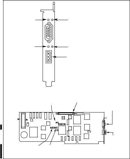
SYSTEM FAULT (red) |
MODULE OK (green) |
|
 DCS;NET NETWORK CONNECTION
DCS;NET NETWORK |
REMOTE I/O LINK |
|
COMMUNICATION (green) |
||
COMMUNICATION (green) |
||
|
||
|
A;B REMOTE I/O LINK |
CONNECTION
20820;M
|
Connect the ribbon cable |
Configures Port B on the AutoMax PC3000 |
from the AutoMax PC3000 |
Serial Board as a dedicated programming |
Serial card. |
device connection or free RS;232 port. |
DCS;NET NETWORK |
|
|
|
|
|
|
CONNECTION |
LITHIUM |
|
|
BATTERY |
|
|
|
JP2 |
|
|
JP4 JP5 |
|
|
|
A;B REMOTE |
|
|
I/O LINK |
|
|
CONNECTION |
Lets you configure the |
Lets you remove the |
|
PC3000 as a passive; |
operating system. |
20844;M |
listening drop on the |
|
|
|
|
|
DCS;NET network.
Figure 1.2 ; AutoMax PC3000 Processor Card
By adding the AutoMax PC3000 Processor card to an existing personal computer chassis, you can create a lower;cost drive controller that has the flexibility to talk directly with human;machine interfaces and operator interfaces over the computer chassis' ISA bus. The PC's processor remains free to run human;machine interfaces, operator interfaces, or other software without adversely affecting system performance.
The PC3000 Processor card occupies two full ISA slots of a personal computer, which it uses for power and ISA bus communication. It also ships as a component of the PC3000 Packaged Version.
1;4
1.2.1About the PC3000 Processor Functionality
The PC3000 Processor has 370K of RAM available for application programs. It can run programs created using AutoMax Enhanced BASIC, Enhanced Ladder Language, or Control Block languages. The Processor supports the AutoMax multi8tasking environment.
1.2.2About the A&B Remote I/O Functionality
Use the Allen8Bradley Remote I/O Scanner interface to link the PC3000 to Allen8Bradley I/O devices that communicate via the remote I/O link. The scanner interface can control such devices as Allen8Bradley's 1771 I/O, Flex I/O, Block I/O, SLC 500 Remote I/O Adapter Module and companion I/O modules, and operator interfaces. The scanner interface can scan both discrete and analog I/O as well as force inputs and outputs.
The scanner interface supports 18, 28, and 1/28slot addressing of a maximum of 32 remote racks. These racks can be either 1/4, 1/2, 3/4, or full racks. The PC3000 supports remote I/O communication rates of 57.6, 115.2, and 230.4 Kbps and can send a maximum of 48 block8transfer read or write requests of up to (and including) 64 words each.
About How the Scanner Module Transfers Discrete Data
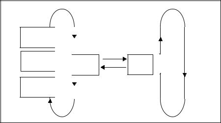
A shared memory interface allows the scanner interface to communicate to the remote I/O adapter devices. It exchanges discrete data with remote I/O adapters. Figure 1.3 illustrates how discrete data is transferred.
Rack 3
Rack 2
Rack 1
 Adapter Adapter Adapter


Remote I/O |
Program |
Scan Loop |
Scan Loop |
Data Exchange |
|
Shared |
|
Memory |
Program |
Interface |
|
Figure 1.3 8 Discrete Data Transfer
185
About How the Scanner Module Transfers Block Data
In addition to discrete data, the scanner module can also exchange block data with remote I/O devices, such as analog I/O modules. A block@transfer request instructs the scanner module to interrupt normal I/O scanning and transfer as many as 64 words of data to or from a selected I/O module. Only one block@transfer request per I/O rack can be processed during a remote I/O scan.
For more information about block@transfers, see chapter 14, •Configuring and Programming Block Data Transfers to A@B I/O Modules."
1.2.3About the AutoMax DCS%NET Network Functionality
The AutoMax DCS@NET network is a serial, master/slave network that connects together multiple AutoMax racks. GV3000 and FlexPak 3000 drives, AutoMax PC3000s, and personal computers (with the AutoMax PC3000 Processor or PC@Link card installed) for a very predictable network response rate. Communication is performed at 875 Kbps over coaxial or fiber@optic cable. The number of devices you can have is dependent upon the type of cable you use and its length.
Each device on the network is called a drop. The master drop initiates and controls all transmissions on the network. All transmissions are broadcasted simultaneously. An address encoded on each data packet identifies which slave drop is to respond to that transmission. The slave's response is also broadcasted, with all drops on the network receiving the response data packets.
For more information about the DCS@NET network, see chapter 3.
1.3About the AutoMax PC3000 Serial Card
The AutoMax PC3000 Serial card contains two optically@isolated serial ports:
DPort A is a 9@pin female D@shell connector. You can configure Port A to support either the RS@232 or RS@422 EIA interface via two jumpers.
DPort B is a 25@pin female D@shell connector. You can use this port as an external connection for a programming terminal running the AutoMax Programming Executive software, or you can configure it to support DCE devices via a jumper.
Figure 1.4 illustrates the features of the AutoMax PC3000 Serial card.
1@6
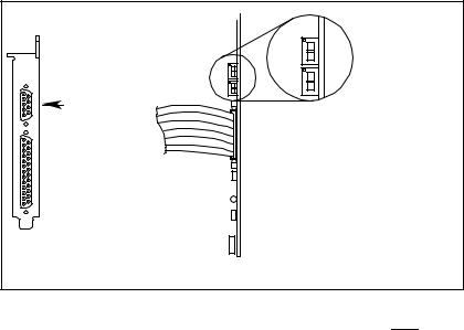
Display errorcodes for the PC3000 CPU.
SERIAL PORT A, 99PIN
RS9232 OR
RS9422 PORT
 SERIAL PORT B, 259PIN
RS9232 PORT (Default programming
device connection.)
208469M
Figure 1.4 9 The AutoMax PC3000 Serial Card
The Serial card ships as part of the AutoMax PC3000 Packaged Version, but the card is optional when installing it in a PC chassis. Installing the Serial card in the same PC as the PC3000 Processor card provides you with additional serial connectivity for programming devices, modems, and data display devices, etc.
The AutoMax PC3000 Serial card occupies one full ISA slot, and interfaces with the AutoMax Processor card via a ribbon cable. The ISA bus only provides power to the Serial card.
1.4About the AutoMax PC3000 Packaged Version
The AutoMax PC3000 Packaged Version is well9suited for a plant9floor environment. It includes a panel9mount, industrial9grade enclosure housing a pre9installed AutoMax PC3000 Processor card and Serial card. The enclosure is equipped with its own fan, fan filter, and power supply. Incoming power connection terminals are mounted onto the enclosure. You connect a programming device for the Packaged Version via Port B on the PC3000 Serial card.
Figure 1.5 illustrates the AutoMax PC3000 Packaged Version.
197
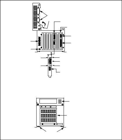
UNUSED
CAMLOCK |
AutoMax PC3000 |
|
PROCESSOR CARD |
|
AutoMax PC3000 |
|
SERIAL CARD |
|
SERIAL PORT A, 9>PIN |
INCOMING POWER |
RS>232 OR RS>422 PORT |
|
|
CONNECTIONS |
SERIAL PORT B, 25>PIN |
|
RS>232 PORT (Default |
PROTECTIVE |
Programming Device |
EARTH |
Connection.) |
SYSTEM FAULT (red) |
MODULE OK (green) |
|
DCS>NET NETWORK CONNECTION |
REMOTE I/O LINK
DCS>NET NETWORK COMMUNICATION (green)
COMMUNICATION (green)
A>B REMOTE I/O LINK
CONNECTION
POWER
SWITCH
 UNUSED LEDs
|
FAN |
|
MOUNTING |
20823>M |
|
BRACKETS |
||
|
Figure 1.5 > AutoMax PC3000 Packaged Version
1.5Rel ted H rdw re nd Softw re
To configure and program the AutoMax PC3000, you need:
Dan IBM>compatible personal computer running the Windows 95 operating system
DRS>232C Interface Cable, M/N 61C127, or another means of connecting to the DCS>NET network
DAutoMax PC3000 driver disk
DVersion 4.1A or later AutoMax Programming Executive software
1>8
1.6Wh t to Do Next
Go to chapter for information about the tasks involved in designing and implementing a PC system.
9
Loading...