


 Loading...
t a
cal n a it
I a ac io J

The information in this user's manual is subject to change without notice.
DANGER
ONLY QUALIFIED ELECTRICAL PERSONNEL FAMILIAR WITH THE CONSTRUCTION AND OPERATION OF THIS EQUIPMENT AND THE HAZARDS INVOLVED SHOULD INSTALL, ADJUST, OPERATE, OR SERVICE THIS EQUIPMENT. READ AND UNDERSTAND THIS MANUAL AND OTHER APPLICABLE MANUALS IN THEIR ENTIRETY BEFORE PROCEEDING. FAILURE TO OBSERVE THIS PRECAUTION COULD RESULT IN SEVERE BODILY INJURY OR LOSS OF LIFE.
WARNING
THE USER MUST PROVIDE AN EXTERNAL, HARDWIRED EMERGENCY STOP CIRCUIT OUTSIDE THE CONTROLLER CIRCUITRY. THIS CIRCUIT MUST DISABLE THE SYSTEM IN CASE OF IMPROPER OPERATION. UNCONTROLLED MACHINE OPERATION MAY RESULT IF THIS PROCEDURE IS NOT FOLLOWED. FAILURE TO OBSERVE THIS PRECAUTION COULD RESULT IN BODILY INJURY.
Ethernet is a trademark of Xerox Corporation.
Microsoft , Windows , Windows 95 , OS/2 , MS.DOS , and WordPad are trademarks of Microsoft.
Multibus is a trademark of Intel.
AutoMate, AutoMax, ReSource, R.Net, and Shark are trademarks of Rockwell Automation. Reliance Electric is a trademark of Rockwell Automation, a core business of Rockwell
International Corporation.

Preface
AutoMax Ladder Editor Feature Overview
The AutoMax Ladder Editor ships as part of the AutoMax Programming Executive. It can be run from within the Executive or as a stand6alone application for offline programming only. The Editor provides these features to help you create your ladder programs:
More easily view and work with rungs in the same praogram or in different programs.
Because the Editor is based on Microsoft Windows 95 , you can:
DUse familiar menu commands and toolbar icons for typical Windows features like restore, maximize, open, save, cut, copy, and more
DDisplay multiple rungs at the same time
DDisplay rungs from different parts of the program at the same time
DDisplay rungs from more than one program at the same time
DUse pop6up menus to access frequently used commands
More easily edit ladder programs.
Because of the drag6and6drop functionality and property sheets for each program element you can:
DCut, copy, paste individual instructions and rungs or groups of instructions and rungs
DMove rungs by selecting them and dragging them with the mouse
DCreate a •work6in6progress program" by building rungs without variable names or coils when you end an editing session
DInsert instructions and branches, or change an instruction type or variable name without any re6typing
DReduce the amount of typing by importing the variable descriptions for global variables from the Variable Configurator. Also, while entering variable names, you can choose from a list of smart6matched names
DInsert new rungs without renumbering existing rungs
DAdd rung descriptions which become part of the rung
Create programs using an enhanced set of ladder insatructions.
The AutoMax Ladder language has been enhanced to include support for:
DAn expanded instruction set based on the IEC6113163 standard
DVariable names of up to 16 characters
DMultiple coils per rung
DMore instructions per rung and more parallel branches
DEasier access to bits within integers and arrays, for example: INPUT_VAR.31 or array_var[index].bit_num
IV

ore easily edit online programs.
When editing an online program you can:
DIdentify inserted, deleted, or modified rungs
DView the original program while you are editing an online version of the same program
DMonitor and modify timer and counter preset values
DTest online edits before permanently downloading them to the Processor
DSet, force, and unforce variables from within the Editor
Where to Find ore Information
This instruction manual describes the AutoMax Enhanced Ladder Editor. For information about the Ladder language, refer to instruction manual J223094. The information in both instruction manuals can also be accessed in the AutoMax Ladder Editor and Enhanced Ladder Language help file (MAXED.HLP). The help file contains additional information not found in either instruction manual.
For more information about the AutoMax Programming Executive, refer to J223089.
The thick black bar shown at the right2hand margin of this page will be used throughout this instruction manual to signify new or revised text or figures.
V

Table of Contents
1.0 Getting Familiar with the Editor . . . . . . . . . . . . . . |
. . . . . . . . . . . . P. . . . |
1 1 |
|
1.1 |
Overview of the AutoMax Ladder Editor Window . . . . . . . . . . . . . |
1=1 |
|
1.2 |
Opening Programs . . . . . . . . . . . . . . . . . . . . . . |
. . . . . . . . . . . . . . . . . |
1=2 |
1.3 |
Closing Programs . . . . . . . . . . . . . . . . . . . . . . . |
. . . . . . . . . . . . . . . . |
1=3 |
1.4 |
Saving Programs . . . . . . . . . . . . . . . . . . . . . . . . |
. . . . . . . . . . . . . . . . |
1=3 |
1.5 |
Saving Programs Automatically As You Work . . . . . . . . . . . . . . . . |
1=4 |
|
1.6 |
Displaying a Program in Multiple Windows . . |
. . . . . . . . . . . . . . . . |
1=4 |
1.7 |
Editing Different Parts of the Same Program Using |
|
|
|
Split Windows . . . . . . . . . . . . . . . . . . . . . . . . . . . |
. . . . . . . . . . . . . . . . |
1=5 |
1.8 |
Editing Multiple Programs . . . . . . . . . . . . . . . . . |
. . . . . . . . . . . . . . . . |
1=5 |
1.9 |
Displaying/Hiding Revision Marks While Editing |
|
|
|
Programs Offline . . . . . . . . . . . . . . . . . . . . . . . . . |
. . . . . . . . . . . . . . . . |
1=6 |
1.10 |
About Program Properties . . . . . . . . . . . . . . . . |
. . . . . . . . . . . . . . . . |
1=7 |
1.11 |
About Program Execution . . . . . . . . . . . . . . . . . |
. . . . . . . . . . . . . . . . |
1=7 |
|
1.11.1 Specifying a Scan Time to Control Program Execution . . |
1=8 |
|
|
1.11.2 Specifying a Hardware Event to Control |
|
|
|
Program Execution . . . . . . . . . . . . . . . . . |
. . . . . . . . . . . . . . . . |
1=8 |
|
1.11.3 Specifying a Software Event to Control Program |
|
|
|
Execution . . . . . . . . . . . . . . . . . . . . . . . . . |
. . . . . . . . . . . . . . . . |
1=9 |
1.12 |
Running and Stopping Ladder Programs . . . |
. . . . . . . . . . . . . . . . |
1=10 |
1.13 |
Exiting the Ladder Editor . . . . . . . . . . . . . . . . . . |
. . . . . . . . . . . . . . . . |
1=10 |
2.0 Editing Programs . . . . . . . . . . . . . . . . . . . . . . . . . . |
P. . . . . . . . . . . . . . . . |
2 1 |
|
2.1 |
Starting a Rung . . . . . . . . . . . . . . . . . . . . . . . . . . |
. . . . . . . . . . . . . . . . |
2=1 |
|
2.1.1 Defining the Horizontal and Vertical |
|
|
|
Grid Limits Per Rung . . . . . . . . . . . . . . . |
. . . . . . . . . . . . . . . . |
2=2 |
|
2.1.2 Turning the Grid On and Off . . . . . . . . . |
. . . . . . . . . . . . . . . . |
2=2 |
2.2 |
Selecting Rungs . . . . . . . . . . . . . . . . . . . . . . . . . |
. . . . . . . . . . . . . . . . |
2=2 |
2.3 |
Entering Rung Descriptions . . . . . . . . . . . . . . . |
. . . . . . . . . . . . . . . . |
2=4 |
2.4 |
Inserting Instructions into a Rung . . . . . . . . . . |
. . . . . . . . . . . . . . . . |
2=5 |
2.5 |
Connecting Instructions (Drawing Wires) . . . . |
. . . . . . . . . . . . . . . . |
2=6 |
2.6 |
Connecting Multiple Instructions by Using the ENO |
|
|
|
Output Bit . . . . . . . . . . . . . . . . . . . . . . . . . . . . . . . |
. . . . . . . . . . . . . . . . |
2=6 |
2.7 |
Selecting Instructions . . . . . . . . . . . . . . . . . . . . |
. . . . . . . . . . . . . . . . |
2=7 |
2.8 |
About Instruction Properties . . . . . . . . . . . . . . . |
. . . . . . . . . . . . . . . . |
2=8 |
2.9 |
Changing an Instruction Type . . . . . . . . . . . . . |
. . . . . . . . . . . . . . . . |
2=9 |
2.10 |
Assigning Variables and Constants to Ladder Instruction |
|
|
|
Parameters . . . . . . . . . . . . . . . . . . . . . . . . . . . . . |
. . . . . . . . . . . . . . . . |
2=10 |
2.11 |
Entering Variable Descriptions . . . . . . . . . . . . . |
. . . . . . . . . . . . . . . . |
2=11 |
2.12 |
Using Variable Smart=Matching . . . . . . . . . . . . |
. . . . . . . . . . . . . . . . |
2=12 |
2.13 |
Selecting Variable Names . . . . . . . . . . . . . . . . . |
. . . . . . . . . . . . . . . . |
2=13 |
2.14 |
Changing a Variable's Data Type . . . . . . . . . . . |
. . . . . . . . . . . . . . . . |
2=13 |
2.15 |
Changing a Variable's Scope . . . . . . . . . . . . . . |
. . . . . . . . . . . . . . . . |
2=14 |
3.0 Printing Programs . . . . . . . . . . . . . . . . . . . . . . . . . . P. . . . . . . . . . . . . . . . 3 1
3.1 What Is Included in a Printed Copy of a Program . . . . . . . . . . . . . 3=2 3.2 Setting Print Options . . . . . . . . . . . . . . . . . . . . . . . . . . . . . . . . . . . . . 3=4 3.3 Defining the Page Setup . . . . . . . . . . . . . . . . . . . . . . . . . . . . . . . . . . 3=5 3.4 How a Rung Is Printed To Fit on a Single Page . . . . . . . . . . . . . . . 3=6
I

|
3.5 |
Inserting and Deleting Page Breaks . . . . . . . . |
. . . . . . . . . . . . . . . |
. 3:7 |
|
3.6 |
Printing a Range of Rungs . . . . . . . . . . . . . . . . |
. . . . . . . . . . . . . . . |
. 3:7 |
|
3.7 |
Displaying and Printing Coils as Right:Justified . . . . . . . . . . . . . |
. 3:8 |
|
|
3.8 |
Printing Multiple Copies of Programs . . . . . . . |
. . . . . . . . . . . . . . . |
. 3:8 |
4.0 |
Verifying Programs . . . . . . . . . . . . . . . . . . . . . . . . . . |
a. . . . . . . . . . . . . . |
. 4 1 |
|
|
4.1 |
Creating a Verify Error Log File . . . . . . . . . . . . |
. . . . . . . . . . . . . . . |
. 4:2 |
|
4.2 |
Automatically Checking the Variable Configurator Database |
|
|
|
|
While Verifying a Program . . . . . . . . . . . . . . . . . |
. . . . . . . . . . . . . . . |
. 4:2 |
|
4.3 |
Specifying Whether To Include Warning Messages When |
|
|
|
|
Verifying Programs . . . . . . . . . . . . . . . . . . . . . . . |
. . . . . . . . . . . . . . . . |
4:3 |
|
4.4 |
Resolving Verify Errors . . . . . . . . . . . . . . . . . . . |
. . . . . . . . . . . . . . . . |
4:3 |
5.0 |
Editing Programs Online . . . . . . . . . . . . . . . . . . . . . |
. . . . . a. . . . . . . . . . |
5 1 |
|
|
5.1 |
About the States of Online Programs . . . . . . . |
. . . . . . . . . . . . . . . . |
5:2 |
|
5.2 |
Monitoring an Online Ladder Program . . . . . . |
. . . . . . . . . . . . . . . . |
5:4 |
|
5.3 |
Pausing the Editor . . . . . . . . . . . . . . . . . . . . . . . |
. . . . . . . . . . . . . . . . |
5:5 |
|
5.4 |
About Power Flow . . . . . . . . . . . . . . . . . . . . . . . |
. . . . . . . . . . . . . . . . |
5:5 |
|
5.5 |
Monitoring Data in an Online Program . . . . . . |
. . . . . . . . . . . . . . . . |
5:6 |
|
5.6 |
Accepting Changes Made to Online Programs . . . . . . . . . . . . . . . |
5:6 |
|
|
5.7 |
Downloading Changes Made to an Online Program |
|
|
|
|
(Commit Online Changes) . . . . . . . . . . . . . . . . |
. . . . . . . . . . . . . . . . |
5:7 |
|
5.8 |
Testing Programs (Test Mode) . . . . . . . . . . . . . |
. . . . . . . . . . . . . . . . |
5:9 |
|
|
5.8.1 Committing an Online Program in Test Mode |
|
|
|
|
(Commit Changes in Test Mode) . . . . . |
. . . . . . . . . . . . . . . . |
5:9 |
|
|
5.8.2 Removing an Online Program from Test Mode . . . . . . . . . |
5:10 |
|
|
|
5.8.3 Canceling All Changes Made to an Online Program . . . . 5:10 |
||
|
5.9 |
About How Changes Made to Online Programs Are Verified . . . |
5:11 |
|
|
5.10 |
Viewing an Online Program as It Looked before It Was Edited |
. 5:12 |
|
|
5.11 |
Capturing the State of Logic in an Online Program . . . . . . . . . . . |
5:13 |
|
|
|
5.11.1 Capturing the State of Logic Based on a Coil |
|
|
|
|
Becoming True . . . . . . . . . . . . . . . . . . . . |
. . . . . . . . . . . . . . . . |
5:14 |
|
|
5.11.2 Capturing the State of Logic Based on a Coil |
|
|
|
|
Becoming False . . . . . . . . . . . . . . . . . . . |
. . . . . . . . . . . . . . . . |
5:14 |
|
|
5.11.3 Capturing the State of Logic Based on a Rung Error . . . . |
5:15 |
|
|
|
5.11.4 Waiting for Triggers While Continuing To Edit . . . . . . . . . . |
5:15 |
|
|
|
5.11.5 Re:Activating a Trigger . . . . . . . . . . . . . . |
. . . . . . . . . . . . . . . . |
5:15 |
|
|
5.11.6 Clearing a Trigger . . . . . . . . . . . . . . . . . . |
. . . . . . . . . . . . . . . . |
5:16 |
|
5.12 |
Setting and Forcing Variables in Ladder Programs . . . . . . . . . . . |
5:16 |
|
|
|
5.12.1 Setting Variables . . . . . . . . . . . . . . . . . . . |
. . . . . . . . . . . . . . . . |
5:18 |
|
|
5.12.2 Forcing Variables . . . . . . . . . . . . . . . . . . |
. . . . . . . . . . . . . . . . |
5:19 |
|
|
5.12.3 Unforcing Variables . . . . . . . . . . . . . . . . |
. . . . . . . . . . . . . . . . |
5:20 |
|
|
5.12.4 About the Expanded Set/Force/Unforce Dialog Box . . . . . |
5:21 |
|
|
|
5.12.5 Viewing the Total Number of Forced Variables . . . . . . . . . |
5:21 |
|
|
|
5.12.6 Viewing a List of Set or Forced Variables . . . . . . . . . . . . . . |
5:21 |
|
|
|
5.12.7 Unforcing an Entire Force Page . . . . . . |
. . . . . . . . . . . . . . . . |
5:21 |
|
|
5.12.8 Testing If Variables in the Rack Are Forced . . . . . . . . . . . . |
5:22 |
|
|
5.13 |
Viewing and Clearing Run:Time Errors . . . . . . |
. . . . . . . . . . . . . . . . |
5:22 |
II

ppendices
ppendi
Toolbars, Palettes, and the Status Bar . . . . . . . . . . . . . . . . . . . . . . . . . A,1
ppendi B
Keyboard Shortcuts . . . . . . . . . . . . . . . . . . . . . . . . . . . . . . . . . . . . . . . . . B,1
ppendi C
Using the Pre,Defined (Reserved) Ladder Language Variables . . . . C,1
ppendi D
Online Editing Memory Limits . . . . . . . . . . . . . . . . . . . . . . . . . . . . . . . . . |
D,1 |
ppendi E
Rung Execution Order . . . . . . . . . . . . . . . . . . . . . . . . . . . . . . . . . . . . . . . E,1
ppendi F
Converting Ladder Programs Created Using an Older Version
of AutoMax . . . . . . . . . . . . . . . . . . . . . . . . . . . . . . . . . . . . . . . . . . . . . . . . . F,1
ppendi G
Glossary . . . . . . . . . . . . . . . . . . . . . . . . . . . . . . . . . . . . . . . . . . . . . . . . . . . G,1
III

1.0 Getting Familiar with the Editor
This section describes some basic information to help you become familiar with the Editor.
1.1Overview of the AutoMax Ladder Editor Window
Ladder Language Toolbar |
Instruction Palette |
||
Standard Toolbar |
Menu Bar Program Windows |
||
|
|||
|
Editor Window |
||
Minimized Program |
Status Bar |
Rung Status Area |
|
DLadder Language Toolbar: Provides access to the individual ladder instruction palette
DStandard Toolbar: Provides shortcuts to common commands by clicking on a button
DEditor Window: Identifies the name of the currently active program and provides access to the application window controls
DInstruction Palette: Lets you drag and drop instructions into your program
DMenu Bar: Provides access to the available Editor commands, many of which can be accessed via a standard toolbar button or keyboard characters
1&1

DProgram Windows: Presents the open program(s). The name of the program is listed in each window
DRung Status Area: Displays rung numbers, revision marks, set triggers, and indicates active versus non5active powerflow
DMinimized Program: Can help organize many open programs
DStatus Bar: Displays information about the program objects you have selected, the state of the program in the active window, and helpful messages
Refer to Appendix A for more information about the toolbars, instruction palettes, and the status bar.
1.2Opening Programs
Opening a program is the first step in editing it. Before you can open a program, you must have added it to the rack using the Task Manager application.
You can open a program from the Task Manager application or from the AutoMax Ladder Editor.
To open a program from within the Task Manager application
DFrom the Task Manager application, select a task and choose Edit from the Task menu.
To open a program from within the Editor
Step 1. Do one of the following:
DClick on 
or
DFrom the Ladder Editor's File menu, choose Open The Open dialog box is displayed.
Step 2. Choose the location of the file that you want to open. The default drive and directory is the drive and directory from which a program was last opened.
To change this: |
Do this: |
|
|
The drive and |
Click in the Look in list box. From |
directory in which to |
here choose the drive and directory |
search |
that contains the program you want to |
|
open. |
|
|
The directory in which |
Click on a folder or on a file in the list |
to search |
of files and folders contained within a |
|
directory. |
|
|
Step 3. From the list of file names, select the program you want to open. The default file type is ladder programs (*.pc). You can open only .pc programs using the Ladder Editor.
Step 4. Open the file by clicking OK.
If the ladder program was created using an older version ladder editor, the Editor first prompts you to convert the
152
program. To convert the program, choose Yes. For more information, see Appendix F.
You can have at most 15 unique offline programs opened at one time.
1.3Closing Programs
Close the active program with the Close command. The Editor stays active and any other open programs stay open.
The Editor prompts you to save any changes to open programs before closing.
To close a ladder program
Step 1. From the File menu or Program Control Menu, choose Close.
Step 2. If you have made changes to the program since you last saved it, choose one of the following buttons in the message box that asks if you want to save the changes:
To: |
Click: |
|
|
keep the changes |
Yes |
|
|
not save the changes |
No |
|
|
keep the program open |
Cancel |
and cancel the changes |
|
|
|
1.4Saving Programs
Save changes to the active, offline program by using the Save command. The Editor stays active with the same program open after saving the changes.
To save a ladder program
DClick on 
or
DFrom the File menu, choose Save
The Editor saves global and local variables and their descriptions to the program symbol table.
Tip
Any offline revision marks present in the program disappear once you save a program.
Tip
To save changes made to an online program, use the Accept or Commit Test Mode Changes commands. For more information, see Chapter 5.0.
1,3

1.5Saving Programs Automatically As You Work
To make sure that you do not lose work, you can use the Automatic Save Every feature to save your offline ladder programs at a specified interval797for example, every ten minutes. Specify whether you want your programs to be saved automatically and the time interval to use within the General Options tab.
Files that are saved automatically are stored in the same directory as the original ladder program and under the same name. However, the file extension for an automatically saved file is .ASV.
To automatically save programs as you work
Step 1. From the Tools menu, choose Options.
Step 2. On the General tab, choose Automatic Save Every.
Step 3. Using the Minutes spinner box, choose or type the time interval (in minutes) that you want the Editor to wait before it automatically saves the ladder program. Choose an interval from 1 to 120 minutes. The default setting is 10 minutes.
The program is saved at your specified time interval whenever a change to the program has been made since the last automatic save.
If a program you are trying to open has a more current autosaved copy, the Editor prompts you to choose either the autosaved file or the program file you last saved.
The auto8saved copy of a ladder program is deleted whenever you save the program by using the Save command or close the program.
1.6Displaying a Program in Multiple Windows
To help you simultaneously view different parts of a program, you can choose to display it in more than one window. Any changes you make to the program are reflected in the other window(s) in which the program is displayed. When you open a new window, it becomes the active window and is displayed on top of all other open windows.
To display a program in multiple windows
Step 1. Make sure that the program you want to display in a new window is the active program.
Step 2. Do one of the following:
DFrom the Window menu, choose New Window.
or
DWith no program items selected and the mouse pointer positioned in the grid area, click the right mouse button, and choose New Window from the pop8up menu.
The program window name is appended by a •:#". For example, if you chose to display the program LINE_1.pc in a new window, the new program window would be LINE_1.pc:2.
184

1.7Editing Different Parts of the Same Program Using Split Windows
A program window may be split into two horizontal panes. Any editing done in one pane is reflected in the other.
Each pane can be scrolled independently using its own vertical scroll bar.
To view different parts of the same program using the STplit command
Step 1. From the Window menu, choose Split. The cursor turns into a split pointer, a combination up arrow and down arrow.
Step 2. Using the mouse or the up and down arrow keys, position the cursor at the point in the program where you would like to split the screen.
Step 3. Press ENTER or click the mouse button once to position the split between the panes.
To view different parts of the same program by clicking Ton the splitter bar
DWhile pointing to the splitter bar, press the left mouse button, drag the splitter bar to the desired location, and release the button.
To remove the splitter bar
DClick on the splitter bar and drag it to the top or bottom of the window.
or
D Double2click anywhere on the splitter bar.
1.8Editing Multiple Programs
You can edit multiple programs (up to 15) within the Editor at the same time. Each program has its own window. Only one window at a time can be the active window, which you can identify by the highlighted title bar and rung status area.
To edit multiple ladder programs from the Task Manager
Step 1. From the Task Manager, select each ladder program that you want to edit.
Step 2. From the Task Menu, choose Edit. The files you selected are opened along with the Editor.
Step 3. From the Editor's Window menu, select Tile or Cascade. All non2minimized programs are arranged within the Ladder Editor window. Or, use the mouse to arrange the windows on the desktop.
Step 4. Click on the program window to make it active before editing the program.
125

To edit multiple ladder programs from the Editor
Step 1. From the File menu, open all the programs you want to edit.
Step 2. From the Window menu, select Tile or Cascade. All non5minimized programs are arranged within the Ladder Editor window. Or, use the mouse to arrange the windows on the desktop.
Step 3. Click on the program window to make it active before editing the program.
Tip
To switch among the programs you are editing, press CTRL+F6.
1.9Displaying/Hiding Revision Marks While Editing Programs Offline
Revisions are always displayed while you are editing a program online. But you can choose to display offline editing revision marks.
Revisions are marked by a letter in the rung status area and by the modified rung color.
Letter |
Meaning |
M |
Logic was modified, or wires have been added |
|
or deleted. |
|
|
I |
The rung has been inserted. |
|
|
D |
The rung has been deleted. |
|
|
Tip
If you delete a newly inserted rung before committing or saving the change, the rung is deleted. However, it is not marked with a •D" revision mark.
To display/hide revision marks while editing programs offline
Step 1. From the Tools menu, choose Options. A tabbed dialog box is displayed.
Step 2. From the General tab, locate the Miscellaneous group box.
Step 3. Choose the Show Revisions While Offline Editing option. This setting applies to the current and subsequent Editor sessions until you change the setting again.
Step 4. Click OK to accept the new setting.
156

1.10About Program Properties
The Program Properties dialog box contains three tabs:
Use this tab: |
For: |
|
|
Program Info |
viewing information about the program |
|
|
Scan Info |
defining how the program should be |
|
scanned and the program's scan time. |
|
|
Error Log |
viewing the online error log |
|
|
To access Program Properties from the File menu
Step 1. Make sure no rung or instruction is selected.
Step 2. From the File menu, choose Properties. The Program Properties dialog box is displayed.
To access Program Properties from the pop up menu
Step 1. Make sure no rung or instruction is selected, and position the mouse in the program's grid area away from any instruction or wire.
Step 2. Press the right mouse button. A pop4up menu is displayed.
Step 3. From the pop4up menu, choose Properties. The Program Properties dialog box is displayed.
See the AutoMax Enhanced Ladder Language Reference manual, J243094, for how to interpret the entries in the error log. See section
1.11 below for defining program scan time.
1.11About Program Execution
Programs can execute by being scanned or event4driven. An event is a flag or indicator that one program can set or raise and another program can wait for.
Scanned programs execute based on the scan time in ticks you define. For a ladder program, you can define how often you want the program to execute by defining scan time in ticks. The actual scan time of a program is determined by this formula:
c c f c c b f c
You define the tick rate for the Processor module when you add it to your rack configuration. By changing the tick rate, you can change the time base for program execution. This allows you to run a program based on a unit of your choice. You can set the tick rate in increments of 0.5 ms between 0.5 ms and 10.0 ms. The default value is 5.5 ms. The tick rate is defined separately for each Processor in a rack. For more information, see section 1.11.1.
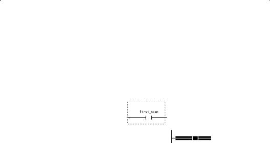
Event4driven programs can be controlled by either hardware events or software events. When an event4driven is first started (run), the program executes once to completion. After this initial execution, the program then waits for the designated event to occur. If you have program logic that you do not want to run during the initial execution of the program, use the pre4defined f c variable. An example is shown here:
147

Hardware events are generated by an external condition. These AutoMax modules can set a hardware event:
DUDC module (57652)
DPulse Tach Input module (57C421)
DResolver Input module (57C411)
D28Channel Analog Input module (57C409)
D328Bit Digital Input module (57C419)
However, hardware events cannot be used on the AutoMax PC3000. See a module's instruction manual for information about interrupts. For more information, see section 1.11.2.
Software events are flags generated by other programs. Software events can be set by BASIC, control block, or ladder programs. For information about programming software events, see your programming language's instruction manual and section 1.11.3.
1.11.1Specifying a Scan Time To Control Program Execution
For a ladder program, you can define how often you want the program to execute by defining scan time in ticks. The actual scan time of a program is determined by this formula:
scan time ms = tick rate of the Processor module e number of ticks
Define the scan time by using the Scan Info tab under Program Properties.
To define how often you want your program to executea
Step 1. Access Program Properties. Make sure no rung or instruction is selected, and choose Properties from the File menu.
Step 2. Choose the Scan Info tab.
Step 3. Select Scanned for the Scan Mode.
Step 4. In the Scan Time (ticks) field, enter the number of ticks you want to use. Enter a value from 1 to 32767. The default value is 20.
For example, if you want a program to execute every 30 ms, and the Processor has a tick rate of 3 ms, enter 10 in the Scan Time field.
Step 5. Click OK to accept the changes.
1.11.2Specifying a Hardware Event To Control Program Execution
Hardware events are generated by an external condition, such as a digital input or a programmed hardware event from a Resolver module. Specify the hardware event that triggers a program's execution by using the Scan Info tab under Program Properties.
188

You can specify a timeout for the hardware event. This lets you specify the maximum amount of time in ticks that can pass before the hardware event occurs. You can use a timeout as a safeguard in case something happens to the module you are using to generate the hardware event. If the event does not occur before the timeout time, a rack STOP ALL error occurs.
To specify a hardware event
Step 1. Access Program Properties. Make sure no rung or instruction is selected, and choose Properties from the File menu.
Step 2. Choose the Scan Info tab.
Step 3. Select Event Driven for the Scan Mode.
Step 4. Select Hardware as the Event Type.
Step 5. In the Name field, type the name of the hardware event that will trigger the program's execution.
Step 6. In the ISCR Variable Name field, type the name of the variable associated with the ISCR (Interrupt status and control) register on the hardware module being used to generate the interrupt.
Step 7. Do one of the following:
To: |
Do this: |
|
|
specify a timeout for the |
a. Select the Timeout |
hardware event |
Enabled |
|
b. Enter an integer value |
|
between 1 and 32767 |
|
You should set the timeout to |
|
a time longer than what you |
|
expect the actual time will be. |
|
A good general rule is 1.5 |
|
times longer than the |
|
expected time between |
|
events. |
|
|
not use a timeout |
Make sure the Timeout |
|
Enabled checkbox is not |
|
selected. |
|
|
8. Click OK to accept the changes.
1.11.3Specifying a Software Event To Control Program Execution
A software event is a flag set by another program. Specify the software event that triggers a program's execution by using the Scan Info tab under Program Properties.
To specify a software event
Step 1. Access Program Properties. Make sure no rung or instruction is selected, and choose Properties from the File menu.
Step 2. Choose the Scan Info tab.
Step 3. Select Event Driven for the Scan Mode.
199

Step 4. Select Software as the Event Type.
Step 5. In the Name field, type the name of the software event that will trigger the program's execution.
Step 6. Click OK to accept the changes.
1.12Running and Stopping Ladder Programs
Use the Online Task Manager to place a program into run or to stop a program. If you are editing online, you must pause the Editor before you can access the Online Task Manager, since they both share the same communication channel. See •Pausing the Editor," section 5.3, for more information.
1.13Exiting the Ladder Editor
Exit the Editor with the Exit command. The Exit command closes all program windows and closes the Editor.
The Editor prompts you to save any changes to open programs before exiting. If you choose to close an online program that has changes that have not been accepted, the Editor prompts you to return to the editing session or close. Selecting close discards all the changes.
To exit the Editor
Step 1. From the File menu, choose Exit.
Step 2. If you have made changes to any open ladder program since you last saved it, choose one of the following buttons in the message box that asks if you want to save the changes:
To: |
Click: |
|
|
keep the changes |
Yes |
|
|
not save the changes |
No |
|
|
not close the program |
Cancel |
|
|
Tip
You can also exit the Editor by choosing Close from the Editor Control menu.
1210

2.0 Editing Programs
This chapter describes how to use the Editor to edit programs offline. See chapter 5 for information about editing programs online.
2.1Starting a Rung
The first step in entering ladder logic is inserting the first instruction in the rung. Place the first instruction of a rung against the left power rail.
All rungs are aligned against the left power rail.
To start a rung
Step 1. Click on the Ladder Language toolbar button that accesses the group of instructions you need.
An instruction palette appears.
Step 2. Point to the instruction you want to insert, and press and hold the left mouse button.
Step 3. While holding down the mouse button, drag the instruction into the program area and next to the left power rail. While you are dragging the instruction, the cursor changes to indicate whether you can drop the instruction and where it will be placed. Instructions
destined for the left power rail will look like  or
or 
Step 4. When the instruction is where you want to place it, release the left mouse button, dropping the instruction into place.
IMPORTANT
You must place the first instruction of a rung so that it attaches to the left power rail to start a rung. If you place it anywhere else in the program window, you must then cut, paste, or drag to connect it to the power rail. You cannot draw a wire to connect it to the left power rail.
Tip
If you frequently use a particular instruction on a toolbar palette, you may want to turn the toolbar palette on. Once a toolbar palette is on, just point to the instruction you want to insert, and press and hold the left mouse button to drag the instruction from the palette.
2+1

2.1.1Defining the Horizontal and Vertical Grid Limits Per Rung
You can define limits for the size of the grid used by the Editor to lay out each rung. This lets you make sure that your program printouts fit on your preferred page size without the rungs being split up.
Relay instructions occupy a grid space of 1 x 1. More complex instructions occupy at least 3 units horizontally by 2 to 8 units vertically.
The default grid size per rung is 40 horizontal units by 24 vertical units, which is also the maximum grid size per rung.
The Editor lets you place instructions outside the grid limits. Rungs that exceed either limit cause a warning to be displayed during a verify operation. The limits you set are checked only when you perform a verify operation.
To define the horizontal and vertical grid limits peRr rung
Step 1. From the Tools menu, choose Options. A tabbed dialog box is displayed.
Step 2. From the General tab, locate the Per Rung Instruction Grid group box.
Step 3. Enter the desired values for the Horizontal and Vertical fields. The Editor uses these new values for all subsequent programs you open.
Step 4. Click OK to accept the new grid size.
2.1.2Turning the Grid On and Off
Use the grid to help you see where instructions will be placed and where you can draw wires. You can select whether to display the grid used by the Editor to lay out rungs. The grid is displayed using + symbols.
To turn the grid on or off from the View menu
D From the View menu, choose Grid.
2.2Selecting Rungs
Before you can copy, cut, or move a rung, you must first select it. You can select a rung by doing any of the following:
DClick on or near the rung number. or
DClick on the rung description text (when displayed). or
DDraw a selection box around the entire rung. A selection box is a dotted9line rectangle like this:
A selected rung looks like this:
292
Tip
If rung numbers are not displayed, you can still select the rung by clicking in the rung status area next to the rung.
To s l ct a rung by rawing a s l ction box
Step 1. Think of the rung you want as being enclosed in a box, and position the pointer on the white space at either the top or bottom •corners."
Step 2. Press the left mouse button. The cursor changes to +.
Step 3. Draw a selection box around the rung by moving the mouse diagonally across the rung. You cannot draw a selection box to encompass more than one rung.
Tip
If the rung you are selecting extends beyond the screen display, you can scroll the screen to display the remaining rung logic by extending the selection box against any side of the program window.
Step 4. Once the rung is enclosed in the box, release the mouse button. The rung is now selected.
To s l ct multipl , contiguous rungs by ragging th h mous
Press and hold the mouse button in the rung status area, and drag the mouse in either direction (up or down) to select additional rungs.
To s l ct multipl , contiguous rungs by s l cting thh first an last rung
Step 1. Select a rung.
Step 2. Scroll the screen as necessary to display the last rung you want to select.
Step 3. Hold down SHIFT and select the last rung by clicking in the rung status area next to the rung.
To s l ct all th rungs in a program
DFrom the Edit menu, choose Select All or
DPress CTRL+A or
DFrom the program window pop1up menu, choose Select All.
213

2.3Entering Rung Descriptions
Rung descriptions help you document the program's logic so that others can understand the function of each rung and help make troubleshooting easier. Rung descriptions can contain a maximum of 16 lines, with each line containing a maximum of 80 characters of text.
You must turn on rung descriptions to view them in the program.
To enter a rung description in the program window
Step 1. Make sure Rung Descriptions are turned on.
Step 2. Select the rung to which you want to add or edit a description. The rung description field, which is a dotted line box, is displayed above the rung. For more information, see section 2.2.
Step 3. Click in the rung description field and enter the description.
Tips
DStart a new line by pressing CTRL+ENTER.
DMove around in the rung description field by using the mouse, HOME, END and the arrow keys. Delete text by using BACKSPACE or DELETE.
DYou can also cut, copy, and paste text in rung descriptions. See the AutoMax Ladder Editor and Enhanced Ladder Editor help file for more information.
To enter a rung description in the Rung Properties dbialog box
Step 1. Select the rung to which you want to add or edit a rung description. For more information, see section 2.2.
Step 2. From the File menu, choose Properties.
Step 3. In the Rung Description field, type in the description.
Step 4. Click OK to add the description.
Tip
You can also access the Rung Properties dialog box from the pop5up menu. Select the rung or point to it. Then, click the right mouse button and choose Properties from the pop5up menu.
254

2.4Inserting Instructions into a Rung
Build a rung by using the mouse to drag and drop instructions from an instruction palette and connect them together by drawing wires. The program area is like a blank canvas242you drag instructions from the instruction palettes and drop them in the program area. But first, you must start a rung by dragging an instruction from an instruction palette and dropping it very near the left power rail. To help make inserting instructions easier, the insert cursor indicates when and in which direction you can drop an instruction. See section 2.1 for more information on starting a rung.
When dropped into the rung, the instructions indicate where you can attach another instruction or wire. Contact instructions have connections on either side, but coil instructions can only connect to another instruction on the left side.
For instruction blocks like ADD, you can connect other instructions to the longer lines. These longer lines attach to Boolean input and output parameters.
An inserted instruction belongs to the rung above it if the newly inserted instruction does not start a rung.
To insert instructions into a rung
Step 1. Click on the Ladder Language toolbar button that accesses the instruction palette you want to use.
The instruction palette appears.
Step 2. Point to the instruction you want to insert.
Step 3. Press and hold the left mouse button while dragging the instruction into the program area.
Step 4. When the pointer is where you want the upper3left corner of the instruction to be, release the left mouse button, dropping the instruction into place.
If you drop an instruction very near another, the newly3placed instruction automatically connects to the one adjacent to it. Similarly, you can insert an instruction between two instructions by simply dragging it between the existing two.
Tip
If you frequently use the instruction on a toolbar palette, you may want to turn the toolbar palette on. See •Turning the Toolbars and Palettes On and Off" in Appendix A.
Tip
If you delete or cut the first instruction of a rung, the left power rail connection stays, indicating that you can insert a new instruction. Insert the new instruction to the right of the left power rail connector.
Tip
You can move or copy one or more instructions from one rung and insert them into another rung. See •Moving Instructions" and •Copying Instructions" in the AutoMAx Ladder Editor online help.
235
2.5Connecting Instructions (Drawing Wires)
Connect instructions when you want to create branches (parallel logic) or to connect two or more instructions together that were placed too far apart for them to connect automatically. Connect instructions by drawing wires.
You can use the grid markers to help you determine where instructions will be placed and where you can draw wires.
To connect instructions
Step 1. Place the cursor near a connection point for an instruction. For relay logic, the connection point is either the left side (for coils) or both sides (for contacts). For block instructions, the connection points are the free ends of the long lines.
When the cursor is near a connection point, it changes to include a pencil: 
Step 2. Press and hold the left mouse button. The cursor changes to a pencil.
Step 3. Draw the wire by moving the mouse towards the instruction to which you want to connect. You can draw a continuous wire to connect instructions in a branch and the coils at the end of the rung. A dotted line indicates where the wire will be placed.
Step 4. When you reach the destination connection point, release the mouse button.
The wire is drawn to connect the instructions.
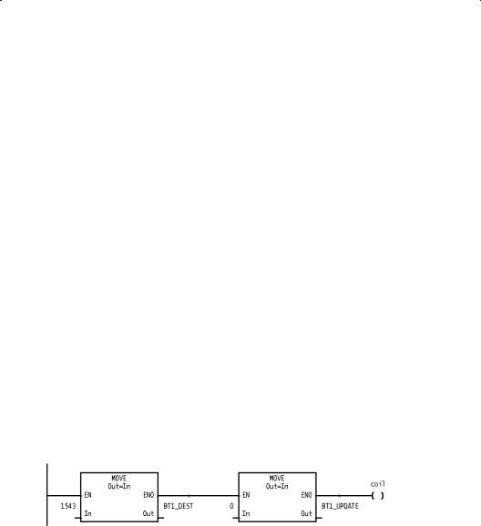
2.6Connecting Multiple Instructions by Using the ENO Output Bit
Quickly build a rung by connecting a relay instruction or a Boolean input of an instruction to the ENO output parameter of an instruction block. For example:
The Boolean input parameter's or relay instruction's state is linked to that of the ENO output parameter.
The ENO output parameter for an instruction follows the state of that instruction's EN input parameter unless an error occurs. When an error occurs within an instruction, the ENO output parameter is set according to the pre3defined variable ERROR_ENO. Because the default value of ERROR_ENO is false, instructions connected to the ENO output are disabled when an error occurs in the instruction block containing the ENO output. Should you want to continue evaluating and executing the logic connected to an ENO output, set the variable ERROR_ENO true.
236
2.7Selecting Instructions
Before you can copy, cut, clear, or move an instruction, you must first select it.
To select an instruction
DClick on any part of the instruction such as the instruction itself, a variable used in the instruction, or the description.
or
DDraw a selection box around the instruction. A selection box is a dotted*line rectangle like this:
A selected instruction looks like this:
To select an instruction by drawing a selection box
Step 1. Think of the instruction you want to select as being enclosed in a box and position the pointer on the white space at either the top or bottom •corners."
Step 2. Press the left mouse button. The cursor changes to +.
Step 3. Draw a selection box around the instruction by moving the mouse diagonally across the instruction. Once the instruction is enclosed in the box, release the mouse button. The instruction is now selected.
2*7

To select multiple, contiguous instructions by drawing a selection box
DDraw a selection box to encompass the instructions you want to select. You can only select instructions that belong to the same rung.
or
Step 1. Select an instruction.
Step 2. While pressing SHIFT, place the mouse pointer on the selected instruction and press the left mouse button.
A selection box appears.
Step 3. While holding down the mouse button, drag the selection box to encompass the instructions that you want to select.
Tip
If the instructions you are selecting extend beyond where they are displayed on the screen, you can scroll the screen to display the remaining instructions by extending the selection box against any side of the program window.
2.8About Instruction Properties
The Instruction Properties dialog box contains two tabs:
Use this tab: |
For: |
|
|
Instruction |
D changing the instruction's type |
Info |
D viewing the variable names used in the |
|
|
|
instruction's input and output parameters |
|
|
Variables |
D viewing the variables used in the instruction |
|
D entering a variable description |
|
D changing variable's data type, scope, |
|
initialization, and display format |
|
D specifying a maximum array index |
|
|
To access Instruction Properties from the File menu
Step 1. Select an instruction.
Step 2. From the File menu, choose Properties. The Instruction Properties dialog box is displayed.
2+8

To access Instruction Properties from the pop up menua
Step 1. Point to the instruction, and press the right mouse button.
Step 2. From the pop8up menu, choose Properties. The
Instruction Properties dialog box is displayed.
To display the variable properties tab, choose Variables. To display information about the instructions, choose Instruction Info. Quickly toggle between the two tabs by using CTRL+TAB.
2.9Changing an Instruction Type
You can change an instruction to another compatible instruction without having to re8enter the variable names for the parameters. This feature helps reduce the time required to make logic changes.
Compatible instructions are those with the same basic function and/or the same number of inputs and outputs. For example, you can change an NOI instruction to a NCI instruction because these instructions are compatible relay input instructions. Conversely, you cannot change an NOI instruction to a CO or an ADD instruction because these instructions are not compatible.
To change an instruction type by using Find and Replaace
Step 1. Click on 
The Find dialog box is displayed.
Step 2. In the Objects group box, choose Instruction.
Step 3. In the Find Instruction list box, choose the instruction for which you want to search. This list only displays those instructions that are compatible with the selected instruction.
Step 4. Choose Find.
The Editor searches the program for the instruction you specified.
Step 5. Choose the Replace button.
Step 6. In the Replace Instruction list box, choose the instruction that you want to use in place of the instruction you are searching for. This list only displays those instructions that are compatible with the selected instruction.
Step 7. Choose Replace to replace the current instruction with the new one or Replace All to replace all occurrences of an instruction with another.
To change an instruction type by using its Instructiaon Properties
Step 1. Select the instruction you want to change.
Step 2. From the File menu, choose Properties.
Step 3. Choose the Instruction Info tab.
Step 4. From the Type list box, choose the instruction type that you want to use in place of the selected instruction. This list only displays those instructions that are compatible with the selected instruction.
Step 5. Click OK to accept the change.
289

Tip
You can also access the Instruction Info tab from the pop1up menu. Point to the instruction that you want to change, press the right mouse button, and choose Properties from the pop1up menu.
Tip
You can also change the information about the variables used in the instruction. Simply choose the Variables tab or press CTRL+TAB to display the Variable Properties.
Tip
To select the instruction and access the pop1up menu, place the mouse pointer over the instruction and click the right mouse button.
2.10Assigning Variables and Constants to Ladder Instruction Parameters
Each instruction includes at least one input or output parameter. The more complex instructions contain parameters for multiple non1Boolean inputs and outputs. Each parameter has a variable name field in which you enter the variable name or constant that you want to assign to the parameter.
To help make assigning variables to instruction parameters easier and faster, variables are automatically assigned a default data type and scope when they are first entered. The default type is that most likely to be used by the instruction. For example, the default type for a variable name entered for a relay instruction is Boolean. But for a JMP, the default type is label. For most block instructions, the default type for input and output parameters is integer.
When you enter an element1indexed variable, a default maximum array index is automatically assigned, which you can later change in the Variable Properties.
The scope of the variable is determined by the case of the first letter of the variable name you type. If the letter is upper case, the variable defaults to being a global variable. If the letter is lower case, the variable defaults to being a local variable.
To assign variables or constants to ladder instructiTon parameters
Step 1. Select the instruction for which you want to assign variables. The variable name field appears as a dotted1line box.
Step 2. Click in this dotted1line box. The outline becomes solid and a vertical text cursor appears.
Step 3. Type in the variable name or a constant you want to use following the naming conventions of the Editor. See the reference information for the instruction you are programming for more information about the allowable variable types. The scope of a variable can be either global or local. When you first enter a variable, its scope is defined based on the case of the first letter you type. An upper case letter defines the variable to be global. A lower case letter defines it to be local. See section 2.15 for more information about a variable's scope.
2110

Tip
If the variable has not been used before, a default data type and scope is automatically assigned. If the variable is an array, the maximum array index defaults to the value you entered as the element of the variable. For example, if you entered part[5] the value of 5 would be entered into the Maximum Array Index field of the Variable Properties.
If the element;index of an array is a variable, the Maximum Array Index field contains a value of 1.
Tip
If the variable has been used before, you can save typing by using Variable Smart;Matching. See section 2.12 for more information about Variable Smart;Matching.
Tip
To enter hexadecimal constants:
DEnd hexadecimal constants with an •h" or •H". For example: 607H
DIf the hexadecimal constant begins with a letter, enter a leading 0 before the value.
For example: 0A607H
DIf the most significant bit of the hexadecimal constant is set and the constant is fewer than 8 digits, sign;extend it with •F's" into an 8;digit hexadecimal value.
For example: Enter 9C40H as 0FFFF9C40H
The Editor converts a hexadecimal value to a decimal constant, except for the logical and Masked Move instructions.
2.11Entering Variable Descriptions
Variable descriptions help you document variables used in instructions. Each variable can have its own description; however, the description applies to simple or array variables and not to indexed variable names. For example, the description displayed for the variable TANK.fill would be for the variable TANK.
The descriptions can contain a maximum of 40 characters.
You must turn on variable descriptions to view them.
To enter a variable description by clicking into thec variable description field above a variable
Step 1. Make sure that the variable descriptions are turned on.
Step 2. Select the instruction.
Step 3. Click in the variable description field above the variable for which you want to enter a description. When selected, the variable description field is outlined by a solid border.
Step 4. Enter a description containing a maximum of 40 characters.
Tip
A shortcut to entering a variable description is to click twice on the variable name and press TAB to advance to the variable description field. Enter a maximum of 40 characters of text.
2;11
Loading...