


 Loading...
User Manual
PowerFlex DC Stand Alone Regulator and Gate
Amplifier
Important User Information
Solid-state equipment has operational characteristics differing from those of electromechanical equipment. Safety Guidelines for the Application, Installation and Maintenance of Solid State Controls (publication SGI-1.1 available from your local Rockwell Automation sales office or online at http://www.rockwellautomation.com/literature/) describes some important differences between solid-state equipment and hard-wired electromechanical devices. Because of this difference, and also because of the wide variety of uses for solid-state equipment, all persons responsible for applying this equipment must satisfy themselves that each intended application of this equipment is acceptable.
In no event will Rockwell Automation, Inc. be responsible or liable for indirect or consequential damages resulting from the use or application of this equipment.
The examples and diagrams in this manual are included solely for illustrative purposes. Because of the many variables and requirements associated with any particular installation, Rockwell Automation, Inc. cannot assume responsibility or liability for actual use based on the examples and diagrams.
No patent liability is assumed by Rockwell Automation, Inc. with respect to use of information, circuits, equipment, or software described in this manual.
Reproduction of the contents of this manual, in whole or in part, without written permission of Rockwell Automation, Inc., is prohibited.
Throughout this manual, when necessary, we use notes to make you aware of safety considerations.
WARNING: Identifies information about practices or circumstances that can cause an explosion in a hazardous environment, which may lead to personal injury or death, property damage, or economic loss.
ATTENTION: Identifies information about practices or circumstances that can lead to personal injury or death, property damage, or economic loss. Attentions help you identify a hazard, avoid a hazard, and recognize the consequence
SHOCK HAZARD: Labels may be on or inside the equipment, for example, a drive or motor, to alert people that dangerous voltage may be present.
BURN HAZARD: Labels may be on or inside the equipment, for example, a drive or motor, to alert people that surfaces may reach dangerous temperatures.
IMPORTANT Identifies information that is critical for successful application and understanding of the product.
Allen-Bradley, PowerFlex, Rockwell Software, Rockwell Automation, and TechConnect are trademarks of Rockwell Automation, Inc.
Trademarks not belonging to Rockwell Automation are property of their respective companies.

Summary of Changes
This manual contains new and updated information.
Topic |
Page |
|
|
Removed the reference to the S12 / S12R configuration from the Features list. |
12 |
|
|
Rockwell Automation Publication 23P-UM001D-EN-P - July 2012 |
3 |

Summary of Changes
4 |
Rockwell Automation Publication 23P-UM001D-EN-P - July 2012 |

Table of Contents
Preface
Introduction
Stand Alone Regulator
Installation, Wiring and
Configuration
Purpose of This Manual . . . . . . . . . . . . . . . . . . . . . . . . . . . . . . . . . . . . . . . . . . . . 7
What This Manual Contains. . . . . . . . . . . . . . . . . . . . . . . . . . . . . . . . . . . . . . . . 7
Drawing Numbers . . . . . . . . . . . . . . . . . . . . . . . . . . . . . . . . . . . . . . . . . . . . . . . . . 7
Additional Resources . . . . . . . . . . . . . . . . . . . . . . . . . . . . . . . . . . . . . . . . . . . . . . . 7
Chapter 1
General Precautions . . . . . . . . . . . . . . . . . . . . . . . . . . . . . . . . . . . . . . . . . . . . . . . . 9
Product Overview . . . . . . . . . . . . . . . . . . . . . . . . . . . . . . . . . . . . . . . . . . . . . . . . 10
Stand Alone Regulator. . . . . . . . . . . . . . . . . . . . . . . . . . . . . . . . . . . . . . . . . . . . 12
Gate Amplifier . . . . . . . . . . . . . . . . . . . . . . . . . . . . . . . . . . . . . . . . . . . . . . . . . . . 12
Chapter 2
Prepare for Installation . . . . . . . . . . . . . . . . . . . . . . . . . . . . . . . . . . . . . . . . . . . 13
Mounting Considerations . . . . . . . . . . . . . . . . . . . . . . . . . . . . . . . . . . . . . . . . 13 CE Conformity . . . . . . . . . . . . . . . . . . . . . . . . . . . . . . . . . . . . . . . . . . . . . . . . . . 16 Terminal/Signal and Wiring Diagrams. . . . . . . . . . . . . . . . . . . . . . . . . . . . . 18 Field Power Module Bridge and Ground Wiring . . . . . . . . . . . . . . . . . . . . 20 AC/DC Voltage and Motor Armature Voltage Feedback Wiring . . . . 21 Power Module Thermal Switch and Current Transformer Wiring . . . 24 SAR Gate Output Cable . . . . . . . . . . . . . . . . . . . . . . . . . . . . . . . . . . . . . . . . . . 25 Control Circuit Power Wiring . . . . . . . . . . . . . . . . . . . . . . . . . . . . . . . . . . . . 25 SAR Motor Field Current Configuration . . . . . . . . . . . . . . . . . . . . . . . . . . 26 SAR Sizing . . . . . . . . . . . . . . . . . . . . . . . . . . . . . . . . . . . . . . . . . . . . . . . . . . . . . . 27 SAR Current Feedback Configuration . . . . . . . . . . . . . . . . . . . . . . . . . . . . . 28 SAR Programming and Startup. . . . . . . . . . . . . . . . . . . . . . . . . . . . . . . . . . . . 40
|
Chapter 3 |
|
Gate Amplifier Installation and |
Prepare for Installation . . . . . . . . . . . . . . . . . . . . . . . . . . . . . . . . . . . . . . . . . . . |
41 |
Wiring |
Operating Temperatures. . . . . . . . . . . . . . . . . . . . . . . . . . . . . . . . . . . . . . . . . . |
41 |
|
Mounting and Cooling . . . . . . . . . . . . . . . . . . . . . . . . . . . . . . . . . . . . . . . . . . . |
42 |
|
Power and Ground Wiring. . . . . . . . . . . . . . . . . . . . . . . . . . . . . . . . . . . . . . . . |
44 |
|
Chassis Grounding . . . . . . . . . . . . . . . . . . . . . . . . . . . . . . . . . . . . . . . . . . . . . . . |
45 |
|
Control Wiring Connections . . . . . . . . . . . . . . . . . . . . . . . . . . . . . . . . . . . . . |
48 |
|
Chapter 4 |
|
Retrofit Guidelines |
Gate Interface to Non-Rockwell Power Module, Retrofit . . . . . . . . . . . . |
59 |
|
Gate Interface to Reliance Electric U.S. Power Modules, Retrofit. . . . . |
61 |
|
Gate Interface to Dierikon Power Modules . . . . . . . . . . . . . . . . . . . . . . . . . |
64 |
|
Chapter 5 |
|
Power Interface and SCR Firing |
Parallel Power Modules and Load Share Reactors . . . . . . . . . . . . . . . . . . . |
65 |
Order |
Phase Sequence and Armature SCR Firing Order . . . . . . . . . . . . . . . . . . . |
65 |
Rockwell Automation Publication 23P-UM001D-EN-P - July 2012 |
5 |

Table of Contents |
|
|
|
Appendix A |
|
Specifications |
Stand Alone Regulator . . . . . . . . . . . . . . . . . . . . . . . . . . . . . . . . . . . . . . . . . . . . |
71 |
|
Gate Amplifier . . . . . . . . . . . . . . . . . . . . . . . . . . . . . . . . . . . . . . . . . . . . . . . . . . . |
71 |
|
Gate Coupler Assembly Information . . . . . . . . . . . . . . . . . . . . . . . . . . . . . . . |
73 |
|
Gate Scaling Module Information. . . . . . . . . . . . . . . . . . . . . . . . . . . . . . . . . . |
76 |
|
Cable Specifications . . . . . . . . . . . . . . . . . . . . . . . . . . . . . . . . . . . . . . . . . . . . . . |
78 |
|
Appendix B |
|
History of Changes |
23P-UM001C-EN-P, September, 2011 . . . . . . . . . . . . . . . . . . . . . . . . . . . . |
83 |
|
23P-UM001B-EN-P, |
|
|
April 2011 . . . . . . . . . . . . . . . . . . . . . . . . . . . . . . . . . . . . . . . . . . . . . . . . . . . . . . . |
83 |
Index |
. . . . . . . . . . . . . . . . . . . . . . . . . . . . . . . . . . . . . . . . . . . . . . . . . . . . . . . . . . . . . . . . . |
85 |
6 |
Rockwell Automation Publication 23P-UM001D-EN-P - July 2012 |

Preface
Purpose of This Manual
What This Manual Contains
Drawing Numbers
This manual provides installation instructions and connection and configuration information for the PowerFlex® DC Stand Alone Regulator (SAR) and the Gate Amplifier. It is intended for internal Rockwell Automation use only.
This user manual contains the following sections:
•Description of the SAR and Gate Amplifier products and general integration information
•Installation, connection and configuration instructions for the SAR
•Installation and connection instructions for the Gate Amplifier
•Guidelines for retrofit installations with DC power modules
•SAR and Gate Amplifier specifications
•Specifications for additional components and cables used with the SAR and Gate Amplifier products
Throughout this manual, drawings are identified by an eight-digit number, for example, 99999999. Where a drawing number includes an asterisk (*) in the 8th digit, the “*” represents the latest version number of the drawing, for example, 999999*.
Additional Resources
These documents contain additional information concerning the PowerFlex DC Stand Alone Regulator and related Rockwell Automation products.
Resource |
Description |
|
|
PowerFlex Digital DC Drive User Manual, |
Provides additional installation, configuration, |
publication 20D-UM001 |
and programming information for the Stand |
|
Alone Regulator. |
|
|
Industrial Automation Wiring and Grounding |
Provides general guidelines for installing a |
Guidelines, publication 1770-4.1 |
Rockwell Automation industrial system. |
|
|
Product Certifications website, http://ab.com |
Provides declarations of conformity, certificates, |
|
and other certification details. |
|
|
You can view or download publications at http://www.rockwellautomation.com/ literature/. To order paper copies of technical documentation, contact your local Rockwell Automation distributor or sales representative.
Rockwell Automation Publication 23P-UM001D-EN-P - July 2012 |
7 |

preface
Notes:
8 |
Rockwell Automation Publication 23P-UM001D-EN-P - July 2012 |
Chapter 1
Introduction
General Precautions
Prior to installation of either the Stand Alone Regulator or Gate Amplifier, read the following precautions.
ATTENTION: Energized industrial control equipment can be hazardous. Severe injury or death can result from electrical shock, burn, or unintended actuation of controlled equipment. Hazardous voltages may exist in the cabinet even with the circuit breaker in the off position. Recommended practice is to disconnect and lock out control equipment from power sources, and discharge stored energy in capacitors, if present. If it is necessary to work in the vicinity of energized equipment, the Safety Related Practices of NFPA 70E, “ELECTRICAL SAFETY FOR EMPLOYEE WORKPLACES” must be followed. DO NOT work alone on energized equipment!
ATTENTION: The following information is merely a guide for proper installation. The National Electrical Code and any other governing regional or local code will overrule this information. Rockwell Automation cannot assume responsibility for the compliance or the noncompliance to any code, national, local or otherwise for the proper installation of this drive regulator or associated equipment. A hazard of personal injury and/or equipment damage exists if codes are ignored during installation.
ATTENTION: The installation of the Stand Alone Regulator and/or the Gate Amplifier must be planned such that all cutting, drilling, tapping and welding can be accomplished with the Gate Amplifier removed from the enclosure. The Stand Alone Regulator and Gate Amplifier are of the open type construction and any metal debris must be kept from falling into the enclosure. Metal debris or other foreign matter may become lodged in the circuitry resulting in component damage.
ATTENTION: An incorrectly applied or installed Stand Alone Regulator or Gate Amplifier can result in component damage or a reduction in product life. Wiring or application errors, such as, incorrect or inadequate supply voltage or excessive ambient temperatures may result in malfunction of the system.
ATTENTION: Only qualified personnel familiar with DC drives and associated machinery should plan or implement the installation, start-up and subsequent maintenance of the system. Failure to comply may result in personal injury and/or equipment damage.
ATTENTION: The Stand Alone Regulator and Gate Amplifier contain ESD (Electrostatic Discharge) sensitive parts and assemblies. Static control precautions are required when installing, testing, servicing or repairing this assembly. Component damage may result if ESD control procedures are not followed. If you are not familiar with static control procedures, reference A-B publication 8000-4.5.2, “Guarding Against Electrostatic Damage” or any other applicable ESD protection handbook.
Rockwell Automation Publication 23P-UM001D-EN-P - July 2012 |
9 |

Chapter 1 Introduction
Product Overview |
The PowerFlex DC Stand Alone Regulator (SAR) and Gate Amplifier products |
|
provide an integrated solution for controlling external DC power modules. |
|
Stand Alone Regulator (SAR) |
|
The SAR is a DC drive regulator that provides armature regulation, armature |
|
SCR gate signals and a regulated field supply. The SAR field supply consists of a |
|
single phase, two quadrant (non-reversing,) full wave rectified bridge, available as |
|
40 or 70 Amps. The SAR supports an AC line input voltage range of 230VAC to |
|
690VAC and a field input voltage range of 100VAC to 460VAC. |
|
The SAR uses feedback signals from the AC input line to monitor the incoming |
|
voltage level in order to establish the SCR gate firing sequence relative to the AC |
|
line. The SCR gate firing for the field bridge is established from the AC lines that |
|
supply the field, independent of the armature firing circuit. DC feedback signals |
|
are used to monitor the output voltage from the power module. Additionally, |
|
current signals received from current transformers is used by the SAR regulator to |
|
monitor and control current. The SAR catalog numbers are listed in Catalog |
|
Numbers on page 12. The SAR must be used with the Gate Amplifier in order to |
|
interface with a DC power module(s). |
|
Gate Amplifier |
|
The Gate Amplifier is used to amplify the SCR gate signals supplied by a DC |
|
drive regulator. The gate signal source to the Gate Amplifier can be provided by |
|
either the PowerFlex DC SAR, or the SD3000 PLUS. The Gate Amplifier unit |
|
provides a separate input D-Shell connector for each product. The Power |
|
Module Interface (PMI) Rack is also compatible with the Gate Amplifier and |
|
uses the SD3000 PLUS inputs. The Gate Amplifier model number and |
|
corresponding connection cables part numbers are listed in Model and Cable |
|
Model/Part Numbers on page 12. |
|
In addition to amplifying the gate signals, the forward and reverse signals |
|
provided by the Gate Amplifier are “fanned-out” to enable the driving of multiple |
|
power modules. Four S6 bridges forward and four S6 bridges reverse. When the |
|
S6 bridges are connected in an anti-parallel configuration, the topology is an S6R |
|
providing both motoring and regenerative capability. |
|
The external 48V gate power supply capability of the Gate Amplifier provides the |
|
means to supply additional gate current and voltage and also support the firing of |
|
gate coupler boards connected in series (which requires additional voltage). |
|
Connecting gate couplers in series forces the simultaneous firing of the SCRs, |
|
with power connections in series or parallel. An internal “diode OR” circuit |
|
ensures that the gates are powered by whichever gate power supply voltage is the |
|
greater in amplitude, the internal or the external power supply. |
10 |
Rockwell Automation Publication 23P-UM001D-EN-P - July 2012 |
2012 July - P-EN-UM001D-23P Publication Automation Rockwell
11
|
|
|
Gate Cable |
|
V1 U1 |
|
|
Gate Amplifier |
|
|
PowerFlex DC |
PFDC |
FWD |
|
|
Gate Input |
|
||
Stand Alone Regulator |
|
|||
Field Supply |
|
KPT11 |
|
|
40 A or 70 A |
|
(15 Pin D-Shell) |
|
|
(2 Quad) |
|
|
|
REV |
|
All Terminals are located |
SD3K |
|
|
|
on the bottom of the unit. |
FWD IN |
|
|
|
KP |
KA |
KPT31 |
|
C1 D1 |
D C W V U |
1A1 A1 1A2 A2 |
1 2 3 4 5 6 7 8 |
|
|
|
|
SD3K |
|
|
|
|
REV IN |
|
|
Power Module |
|
|
Power Module |
|
|
|
|
|
120VAC |
|||||
|
AC / DC |
|
|
Thermostat and |
|
|
Ext. P/S |
|
|
|
|||||
|
Feedback |
|
|
CT Feedback |
|
|
+ |
|
|
|
|
|
|
||
|
|
|
|
|
|
|
|
RDY |
- |
|
|
|
|
|
|
To Motor |
|
|
|
|
|
|
|
|
|
|
|
|
|||
|
|
|
|
|
|
|
|
|
|
|
|
|
|||
|
Power Module |
|
|
|
|
|
|
|
|
|
|
||||
|
|
|
|
|
|
|
|
||||||||
Field |
Armature Voltage |
|
|
|
|
|
|
|
|
|
|
||||
|
|
|
|
|
|
|
|
||||||||
|
|
|
Feedback |
|
|
|
|
|
|
|
|
|
|
||
|
|
|
|
|
|
|
|
|
|
|
|
|
|
|
|
|
|
|
|
|
|
|
|
|
|
|
|
|
|
|
|
|
|
|
|
|
|
|
|
|
|
|
|
|
|
|
|
|
|
|
|
|
|
|
|
|
|
|
|
|
|
|
|
|
|
|
|
|
|
Normally |
|
|
48V Ext P/S |
||||||
|
|
|
|
|
Open Contacts |
|
|
||||||||
|
|
|
|
|
to Stop Circuitry |
|
|
(If Required) |
|||||||
|
|
|
|
|
|
|
|
|
|
|
|
|
|
|
|
AC
Input
CT FDBK to PFDC SAR |
CTs on |
|
L1 and L3 |
||
|
L1, L2, L3
AC
FWD |
REV |
1 |
1 |
GATE COUPLER
ASSEMBLY
GATE COUPLER
ASSEMBLY
|
M |
+DC and -DC |
From Stand-Alone |
Power Module |
|
Regulator |
|
Output |
|
|
|
Motor Field |
|
Motor |
To Stop |
Encoder or Resolver Feedback |
|
Circuitry |
||
|
To Encoder or Resolver
P/S Feedback Port
MONITOR
RELAY
PowerFlex Typical - 1 Figure S6R to Interface |
|
Amplifier Gate and Regulator Alone Stand DC |
Chapter Introduction |
|
1 |

Chapter 1 Introduction
Stand Alone Regulator Features
•Rockwell Automation Architecture Class networking capable
Available Options
•Resolver Feedback
Catalog Numbers
This table lists the available catalog numbers for the SAR.
|
230V / 460V AC Input |
575V / 690V AC Input |
Field Amps |
|
|
Catalog Number |
Catalog Number: |
|
|
|
23PMD4 |
23PMF4 |
40 |
|
|
23PMD7 |
23PMF7 |
70 |
|
|
Note: All models contain conformal coated circuit boards. |
|||
Gate Amplifier |
Features |
|
|
|
|
• Interfaces to the PowerFlex DC, SD3000 PLUS or PMI regulators |
|||
|
• Flexible configurations S6 and S6R |
|
|
|
• Power module interface
• Interlock via “Ready Relay” contacts to main drive control
Available Options
•48V gate drive capability with an external power supply
Model and Cable Model/Part Numbers
This table lists the cable module numbers and part numbers for the Gate
Amplifier.
Product: |
Model/Part Number: |
Gate Amplifier |
23PAMP |
PowerFlex DC to Gate Amplifier Cable |
See Cable Specifications on page 78. |
SD3000 PLUS to Gate Amplifier Forward Cable |
SD3K-CBLGSCLIFxxx(1) |
SD3000 PLUS to Gate Amplifier Reverse Cable |
SD3K-CBLGSCLIRxxx(1) |
PMI Rack to Gate Amplifier Forward Cable |
612432-xxxS(1) |
PMI Rack to Gate Amplifier Reverse Cable |
612433-xxxS(1) |
(1) xxx = length in inches.
12 |
Rockwell Automation Publication 23P-UM001D-EN-P - July 2012 |

Chapter 2
Stand Alone Regulator Installation, Wiring
and Configuration
Prepare for Installation
Prior to installation of the PowerFlex DC Stand Alone Regulator (SAR) read the General Precautions on page 9.
Mounting Considerations |
Operating Conditions and Temperatures |
|
The SAR is designed to operate at 0°…50° C (32°… 122° F) surrounding air |
|
temperature without derating. The unit must be mounted in a clean, dry location. |
|
Contaminants such as oils, corrosive vapors and abrasive debris must be kept out |
|
of the enclosure. NEMA/UL Type Open, IP20 enclosures are intended for |
|
indoor use primarily to provide a degree of protection against contact with |
|
enclosed equipment. These enclosures offer no protection against airborne |
|
contaminants. |
Rockwell Automation Publication 23P-UM001D-EN-P - July 2012 |
13 |
Chapter 2 Stand Alone Regulator Installation, Wiring and Configuration
Minimum Mounting Clearances
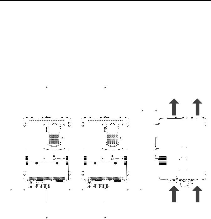
Minimum clearance requirements (indicated in Figure 2 - Drive Enclosure Minimum Mounting Clearances) are intended to be from enclosure to enclosure. Other objects can occupy this space; however, reduced airflow may cause protection circuits to fault the SAR. The SAR must be mounted in a vertical orientation as shown and must not be mounted at an angle greater than 30 degrees from vertical. In addition, inlet air temperature must not exceed the product specification.
Figure 2 - Drive Enclosure Minimum Mounting Clearances
|
|
|
|
|
|
|
|
|
|
|
|
|
|
|
|
|
|
|
|
|
|
|
|
|
|
|
|
|
|
|
|
|
|
|
|
|
|
|
|
Min. 50 mm |
|
|
|
|
|
|
|
|
|
|
|
|
|
|
|
|
|
|
|
|
|
||||
|
|
|
|
|
|
|
|
|
|
|
|
|
|
|
|
|
|
|
|
|
|
|
|
|
|
|
|
|
|
|
|
|
|
|
|
|
|
|
|
|
|
|
|
|
|
|
|
|
|
|
|
|
|
|
|
|
|
|
|
|
|||||
|
|
|
|
|
|
|
|
|
|
|
|
|
|
|
|
|
|
|
|
|
|
|
|
|
|
|
|
|
|
|
|
|
|
|
|
|
|
|
|
|
|
|
|
|
|
|
|
|
|
|
|
|
|
|
|
|
|
|
|
|
|||||
|
|
|
|
|
|
|
Min. 150 mm |
|
|
|
|
|
|
|
|
|
|
|
|
|
Min. 150 mm |
|
|
|
|
|
|
|
|
|
|
|
|
|
|
|
|
|
|
|
|
|
|
|
|
|
|
|
|||||||||||||||||
|
|
|
|
|
|
|
|
|
|
(6.0 in.) |
|
|
|
|
|
|
|
|
|
|
|
|
|
|
|
|
(6.0 in.) |
|
|
|
|
|
|
(2.0 in.) |
|
|
|
|
|
|
|
|
|
|
|
|
|
|
|
|
|
|
|
|
|
||||||||||
|
|
|
|
|
|
|
|
|
|
|
|
|
|
|
|
|
|
|
|
|
|
|
|
|
|
|
|
|
|
|
|
|
|
|
|
|
|
|
|
|
|
|
|
|
|
|
|
|
|
|
|
|
|
|
|
|
|
|
|
|
|
|
|
|
|
|
|
|
|
|
|
|
|
|
|
|
|
|
|
|
|
|
|
|
|
|
|
|
|
|
|
|
|
|
|
|
|
|
|
|
|
|
|
|
|
|
|
|
|
|
|
|
|
|
|
|
|
|
|
|
|
|
|
|
|
|
|
|
|
|
|
|
|
|
|
|
|
|
|
|
|
|
|
|
|
|
|
|
|
|
|
|
|
|
|
|
|
|
|
|
|
|
|
|
|
|
|
|
|
|
|
|
|
|
|
|
|
|
|
|
|
|
|
|
|
|
|
|
|
|
|
|
|
|
|
|
|
|
|
|
|
|
|
|
|
|
|
|
|
|
|
|
|
|
|
|
|
|
|
|
|
|
|
|
|
|
|
|
|
|
|
|
|
|
|
|
|
|
|
|
|
|
|
|
|
|
|
|
|
|
|
|
|
|
|
|
|
|
|
|
|
|
|
|
|
|
|
|
|
|
|
|
|
|
|
|
|
|
|
|
|
|
|
|
|
|
|
|
|
|
|
|
|
|
|
|
|
|
|
|
|
|
|
|
|
|
|
|
|
|
|
|
|
|
|
|
|
|
|
|
|
|
|
|
|
|
|
|
|
|
|
|
|
|
|
|
|
|
|
|
|
|
|
|
|
|
|
|
|
|
|
|
|
|
|
|
|
|
|
|
|
|
|
|
|
|
|
|
|
|
|
|
|
|
|
|
|
|
|
|
|
|
|
|
|
|
|
|
|
|
|
|
|
|
|
|
|
|
|
|
|
|
|
|
|
|
|
|
|
|
|
|
|
|
|
|
|
|
|
|
|
|
|
|
|
|
|
|
|
|
|
|
|
|
|
|
|
|
|
|
|
|
|
|
|
|
|
|
|
|
|
|
|
|
|
|
|
|
|
|
|
|
|
|
|
|
|
|
|
|
|
|
|
|
|
|
|
|
|
|
|
|
|
|
|
|
|
|
|
|
|
|
|
|
|
|
|
|
|
|
|
|
|
|
|
|
|
|
|
|
|
|
|
|
|
|
|
|
|
|
|
|
|
|
|
|
|
|
|
|
|
|
|
|
|
|
|
|
|
|
|
|
|
|
|
|
|
|
|
|
|
|
|
|
|
|
|
|
|
|
|
|
|
|
|
|
|
|
|
|
|
|
|
|
|
|
|
|
|
|
|
|
|
|
|
|
|
|
|
|
|
|
|
|
|
|
|
|
|
|
|
|
|
|
|
|
|
|
|
|
|
|
|
|
|
|
|
|
|
|
|
|
|
|
|
|
|
|
|
|
|
|
|
|
|
|
|
|
|
|
|
|
|
|
|
|
|
|
|
|
|
|
|
|
|
|
|
|
|
|
|
|
|
|
|
|
|
|
|
|
|
|
|
|
|
|
|
|
|
|
|
|
|
|
|
|
|
|
|
|
|
|
|
|
|
|
|
|
|
|
|
|
|
|
|
|
|
|
|
|
|
|
|
|
|
|
|
|
|
|
|
|
|
|
|
|
|
|
|
|
|
|
|
|
|
|
|
|
|
|
|
|
|
|
|
|
|
|
|
|
|
|
|
|
|
|
|
|
|
|
|
|
|
|
|
|
|
|
|
|
|
|
|
|
|
|
|
|
|
|
|
|
|
|
|
|
|
|
|
|
|
|
|
|
|
|
|
|
|
|
|
|
|
|
|
|
|
|
|
|
|
|
|
|
|
|
|
|
|
|
|
|
|
|
|
|
|
|
|
|
|
|
|
|
|
|
|
|
|
|
|
|
|
|
|
|
|
|
|
|
|
|
|
|
|
|
|
|
|
|
|
|
|
|
|
|
|
|
|
|
|
|
|
|
|
|
|
|
|
|
|
|
|
|
|
|
|
|
|
|
|
|
|
|
|
|
|
|
|
|
|
|
|
|
|
|
|
|
|
|
|
|
|
|
|
|
|
|
|
|
|
|
|
|
|
|
|
|
|
|
|
|
|
|
|
|
|
|
|
|
|
|
|
|
|
|
|
|
|
|
|
|
|
|
|
|
|
|
|
|
|
|
|
|
|
|
|
|
|
|
|
|
|
|
|
|
|
|
|
|
|
|
|
|
|
|
|
|
|
|
|
|
|
|
|
|
|
|
|
|
|
|
|
|
|
|
|
|
|
|
|
|
|
|
|
|
|
|
|
|
|
|
|
|
|
|
|
|
|
|
|
|
|
|
|
|
|
|
|
|
|
|
|
|
|
|
|
|
|
|
|
|
|
|
|
|
|
|
|
|
|
|
|
|
|
|
|
|
|
|
|
|
|
|
|
|
|
|
|
|
|
|
|
|
|
|
|
|
|
|
|
|
|
|
|
|
|
|
|
|
|
|
|
|
|
|
|
|
|
|
|
|
|
|
|
|
|
|
|
|
|
|
|
|
|
|
|
|
|
|
|
|
|
|
|
|
|
|
|
|
|
|
|
|
|
|
|
|
|
|
|
|
|
|
|
|
|
|
|
|
|
|
|
|
|
|
|
|
|
|
|
|
|
|
|
|
|
|
|
|
|
|
|
|
|
|
|
|
|
|
|
|
|
|
|
|
|
|
|
|
|
|
|
|
|
|
|
|
|
|
|
|
|
|
|
|
|
|
|
|
|
|
|
|
|
|
|
|
|
|
|
|
|
|
|
|
|
|
|
|
|
|
|
|
|
|
|
|
|
|
|
|
|
|
|
|
|
|
|
|
|
|
|
|
|
|
|
|
|
|
|
|
|
|
|
|
|
|
|
|
|
|
|
|
|
|
|
|
|
|
|
|
|
|
|
|
|
|
|
|
|
|
|
|
|
|
|
|
|
|
|
|
|
|
|
|
|
|
|
|
|
|
|
|
|
|
|
|
|
|
|
|
|
|
|
|
|
|
|
|
|
|
|
|
|
|
|
|
|
|
|
|
|
|
|
|
|
|
|
|
|
|
|
|
|
|
|
|
|
|
|
|
|
|
|
|
|
|
|
|
|
|
|
|
|
|
|
|
|
|
|
|
|
|
|
|
|
|
|
|
|
|
|
|
|
|
|
|
|
|
|
|
|
|
|
|
|
|
|
|
|
|
|
|
|
|
|
|
|
|
|
|
|
|
|
|
|
|
|
|
|
|
|
|
|
|
|
|
|
|
|
|
|
|
|
|
|
|
|
|
|
|
|
|
|
|
|
|
|
|
|
|
|
|
|
|
|
|
|
|
|
|
|
|
|
|
|
|
|
|
|
|
|
|
|
|
|
|
|
|
|
|
|
|
|
|
|
|
|
|
|
|
|
|
|
|
|
|
|
|
|
|
|
|
|
|
|
|
|
|
|
|
|
|
|
|
|
|
|
|
|
|
|
|
|
|
|
|
|
|
|
|
|
|
|
|
|
|
|
|
|
|
|
|
|
|
|
|
|
|
|
|
|
|
|
|
|
|
|
|
|
|
|
|
|
|
|
|
|
|
|
|
|
|
|
|
|
|
|
|
|
|
|
|
|
|
|
|
|
|
|
|
|
|
|
|
|
|
|
|
|
|
|
|
|
|
|
|
|
|
|
|
|
|
|
|
|
|
|
|
|
|
|
|
|
|
|
|
|
|
|
|
|
|
|
|
|
|
|
|
|
|
|
|
|
|
|
|
|
|
|
|
|
|
|
|
|
|
|
|
|
|
|
|
|
|
|
|
|
|
|
|
|
|
|
|
|
|
|
|
|
|
|
|
|
|
|
|
|
|
|
|
|
|
|
|
|
|
|
|
|
|
|
|
|
|
|
|
|
|
|
|
|
|
|
|
|
|
|
|
|
|
|
|
|
|
|
|
|
|
|
|
|
|
|
|
|
|
|
|
|
|
|
|
|
|
|
|
|
|
|
|
|
|
|
|
|
|
|
|
|
|
|
|
|
|
|
|
|
|
|
|
|
|
|
|
|
|
|
|
|
|
|
|
|
|
|
|
|
|
|
|
|
|
|
|
|
|
|
|
|
|
|
|
|
|
|
|
|
|
|
|
|
|
|
|
|
|
|
|
|
|
|
|
|
|
|
Min. 10 0 mm |
|
Min. 10 0 mm |
|
|
Min. 10 0 mm |
||
(0.4 in.) |
|
(0.4 in.) |
Min. 150 mm |
(0.4 in.) |
|||
|
|
Min. 150 mm |
|
Airflow through the unit |
|||
|
|
(6.0 in.) |
(6.0 in.) |
|
|||
|
|
|
must not be impeded. |
||||
|
|
|
|
|
|
|
|
|
|
|
|
|
|
|
|
|
|
|
|
|
|
|
|
|
|
|
|
|
|
|
|
|
|
|
|
|
|
|
|
14 |
Rockwell Automation Publication 23P-UM001D-EN-P - July 2012 |
Stand Alone Regulator Installation, Wiring and Configuration |
Chapter 2 |
|
|
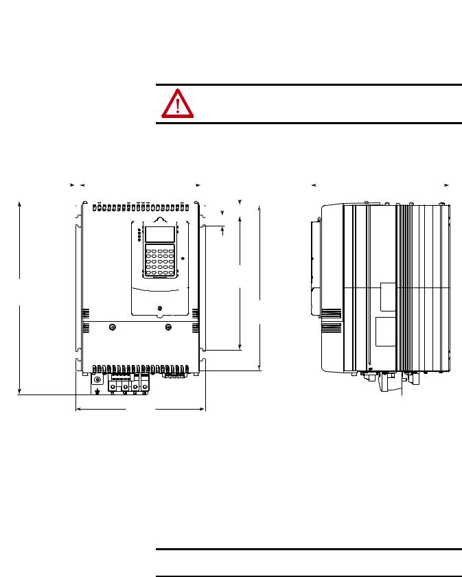
Approximate Dimensions and Weights
The SAR is available in a NEMA/UL Type Open, IP20 enclosure only.
ATTENTION: Remove all loose packaging materials, including any desiccant packages from the enclosure before mounting and energizing the SAR.
|
|
|
|
|
|
|
|
|
|
|
|
|
|
|
|
|
|
|
|
|
|
|
|
|
|
|
|
|
|
|
|
|
|
|
|
|
|
|
|
|
|
|
|
|
|
|
|
|
|
|
|
|
|
|
|
|
|
|
|
|
|
|
|
|
|
|
|
|
|
|
|
Dimensions are shown in mm (in.) |
|
|
|
|
|
|
|
|
|
|
|
|
|||||||||||||||||||||
8.4 (0.33) |
|
|
|
|
|
|
|
|
|
|
|
|
|
|
|
|
|
|
|
|
|
|
|
|
250.0 (9.84) |
|
|
|
|
|
|
|
23.3 |
|
|
|
285.4 (11.24) |
|
|
|
|
||||||||||||||||||||||||||||||||||||||||||||||||||||||||||||||||
|
|
|
|
|
|
|
|
|
|
|
|
|
|
|
|
|
|
|
|
|
|
|
|
|
|
|
|
|
|
|
|
|
|
|
|
|
|
|
|
|
|
(0.92) |
|
|
|
|
|
|
|
||||||||||||||||||||||||||||||||||||||||||||||||||||||||
|
|
|
|
|
|
|
|
|
|
|
|
|
|
|
|
|
|
|
|
|
|
|
|
|
|
|
|
|
|
|
|
|
|
|
|
|
|
|
|
|
|
|
|
|
|
|
|
|
|
|
|
|
|
|
|
|
|
|
|
|
|
|
|
|
|
|
|
|
|
|
|
|
|
|
|
|
|
|
|
|
|
|
|
|
|
|
|
|
|
|
|
|
|
|
|
|
|
|
|
|
|||||
|
|
|
|
|
|
|
|
|
|
|
|
|
|
|
|
|
|
|
|
|
|
|
|
|
|
|
|
|
|
|
|
|
|
|
|
|
|
|
|
|
|
|
|
|
|
|
|
|
|
|
|
|
|
|
|
|
|
|
|
|
|
|
|
|
|
|
|
|
|
|
|
|
|
|
|
|
|
|
|
|
|
|
|
|
|
|
|
|
|
|
|
|
|
|
|
|
|
|
|
|
|
|
|
|
|
|
|
|
|
|
|
|
|
|
|
|
|
|
|
|
|
|
|
|
|
|
|
|
|
|
|
|
|
|
|
|
|
|
|
|
|
|
|
|
|
|
|
|
|
|
|
|
|
|
|
|
|
|
|
|
|
|
|
|
|
|
|
|
|
|
|
|
|
|
|
|
|
|
|
|
|
|
|
|
|
|
|
|
|
|
|
|
|
|
|
|
|
|
|
|
|
|
|
|
|
|
|
|
|
|
|
|
|
|
|
|
|
|
|
|
|
|
|
|
|
|
|
|
|
|
|
|
|
|
|
|
|
|
|
|
|
|
|
|
|
|
|
|
|
|
|
|
|
|
|
|
|
|
|
|
|
|
|
|
|
|
|
|
|
|
|
|
|
|
|
|
|
|
|
|
|
|
|
|
|
|
|
|
|
|
|
|
|
|
|
|
|
|
|
|
|
|
|
|
|
|
|
|
|
|
|
|
|
|
|
|
|
|
|
|
|
|
|
|
|
|
|
|
|
|
|
|
|
|
|
|
|
|
|
|
|
|
|
|
|
|
|
|
|
|
|
|
|
|
|
|
|
|
|
|
|
|
|
|
|
|
|
|
|
|
|
|
|
|
|
|
|
|
|
|
|
|
|
|
|
|
|
|
|
|
|
|
|
|
|
|
|
|
|
|
|
|
|
|
|
|
|
|
|
|
|
|
|
|
|
|
|
|
|
|
|
|
|
|
|
|
|
|
|
|
|
|
|
|
|
|
|
|
|
|
|
|
|
|
|
|
|
|
|
|
|
|
|
|
|
|
|
|
|
|
|
|
|
|
|
|
|
|
|
|
|
|
|
|
|
|
|
|
|
|
|
|
|
|
|
|
|
|
|
|
|
|
|
|
|
|
|
|
|
|
|
|
|
|
|
|
|
|
|
|
|
|
|
|
|
|
|
|
|
|
|
|
|
|
|
|
|
|
|
|
|
|
|
|
|
|
|
|
|
|
|
|
|
|
|
|
|
|
|
|
|
|
|
|
|
|
|
|
|
|
|
|
|
|
|
|
|
|
|
|
|
|
|
|
|
|
|
|
|
|
|
|
|
|
|
|
|
|
|
|
|
|
|
|
|
|
|
|
|
|
|
|
|
|
|
|
|
|
|
|
|
|
|
|
|
|
|
|
|
|
|
|
|
|
|
|
|
|
|
|
|
|
|
|
|
|
|
|
|
|
|
|
|
|
|
|
|
|
|
|
|
|
|
|
|
|
|
|
|
|
|
|
|
|
|
|
|
|
|
|
|
|
|
|
|
|
|
|
|
|
|
|
|
|
|
|
|
|
|
|
|
|
|
|
|
|
|
|
|
|
|
|
|
|
|
|
|
|
|
|
|
|
|
|
|
|
|
|
|
|
|
|
|
|
|
|
|
|
|
|
|
|
|
|
|
|
|
|
|
|
|
19.5
(0.77)
275.0
 (10.83) 397.9


(15.67)
341.0 (13.43)
266.8
(10.51)
Table 1 - Stand Alone Regulator Weights
Stand Alone Regulator |
Stand Alone Regulator and Packaging |
|
|
12.0 kg (26.5 lb) |
14.1 kg (31 lb) |
|
|
Recommended Mounting Hardware: Metric M6, English 1/4 in.
IMPORTANT Provide a minimum of 150 mm (6.0 in.) below the unit for cable connections.
Rockwell Automation Publication 23P-UM001D-EN-P - July 2012 |
15 |

Chapter 2 Stand Alone Regulator Installation, Wiring and Configuration
CE Conformity
Conformity with the Low Voltage Directive and Electromagnetic Compatibility Directive has been demonstrated using harmonized European Norm (EN) standards published in the Official Journal of the European Communities. The PowerFlex DC Stand Alone Regulator complies with the EN standards listed when installed according to this User Manual.
CE Declarations of Conformity are available online at: www.rockwellautomation.com/products/certification/ce/
Low Voltage Directive (2006/95/EC)
• EN 50178 Electronic equipment for use in power installations.
EMC Directive (2004/108/EC)
•EN 61800-3 Adjustable speed electrical power drive systems Part 3: EMC product standard including specific test methods.
General Considerations
•For CE compliance, the SAR installation must satisfy requirements related to both EN 50178 and EN 61800-3 provided in this document.
•The SAR complies with the EMC requirements of EN 61800-3 when installed according to good EMC practices and the instructions provided in this document. However, many factors can influence the EMC compliance of an entire machine or installation, and compliance of the SAR itself does not necessarily ensure compliance of all applications.
•The SAR is not intended to be used on public supply networks which supply domestic premises. Without additional mitigation, radio frequency interference is expected if used on such a network. The installer is responsible to take measures such as supplementary line filters and enclosures to prevent interference, in addition to the installation requirements of this document.
Installation Requirements Related to EN 50178 and the Low Voltage Directive
•The SAR is compliant with the CE LV Directive when used at altitudes no greater than 2000 m (6562 ft).
•The SAR provided in enclosure type IP20 must be installed in a pollution degree 1 or 2 environment to be compliant with the CE LV Directive. Characteristics of the different pollution degree ratings are provided in Table 2 on page 17.
16 |
Rockwell Automation Publication 23P-UM001D-EN-P - July 2012 |

Stand Alone Regulator Installation, Wiring and Configuration Chapter 2
Table 2 - Pollution Degree Ratings According to EN 61800-5-1
Pollution Degree |
Description |
|
|
1 |
No pollution or only dry, non-conductive pollution occurs. The pollution has no |
|
influence. |
|
|
2 |
Normally, only non-conductive pollution occurs. Occasionally, however, a |
|
temporary conductivity caused by condensation is to be expected, when the |
|
drive is out of operation. |
|
|
3 |
Conductive pollution or dry non-conductive pollution occurs, which becomes |
|
conductive due to condensation, which is to be expected. |
|
|
4 |
The pollution generates persistent conductivity caused, for example by |
|
conductive dust or rain or snow. |
|
|
•The SAR must be installed in a suitable enclosure with at least an IP4X rating at the top of the enclosure.
•The SAR may produce leakage current in the protective earthing conductor which exceeds 3.5 mA AC and/or 10 mA DC. The minimum size of the protective earthing (grounding) conductor used in the application must comply with local safety regulations for equipment with high protective earthing conductor current.
•The SAR may not be powered from a “corner-earthed” supply system in order to maintain compliance with the CE LV Directive.
Installation Requirements Related to EN 61800-3 and the EMC Directive
•The SAR must be earthed (grounded) as described in this User Manual.
•Output power wiring to the motor (field excitation) must employ cable with a braided shield providing 75% or greater coverage, or the cable must be housed in metal conduit, or equivalent shielding must be provided. Continuous shielding must be provided from the SAR enclosure to the motor enclosure. Both ends of the motor cable shield (or conduit) must terminate with a low-impedance connection to earth.
•At the motor end, the motor field excitation cable shield or conduit must terminate in a shielded connector which must be properly installed in an earthed motor wiring box attached to the motor. The motor wiring box cover must be installed and earthed.
•All control (I/O) and signal wiring to the SAR, including gate firing control, must use cable with a braided or foil shield providing 75% or greater coverage, or the cables must be housed in metal conduit, or equivalent shielding must be provided. Only the SAR end of the cable shield should be terminated with a low impedance connection to earth.
•Power cabling must be separated from control and signal wiring wherever possible.
Rockwell Automation Publication 23P-UM001D-EN-P - July 2012 |
17 |
Chapter 2 Stand Alone Regulator Installation, Wiring and Configuration
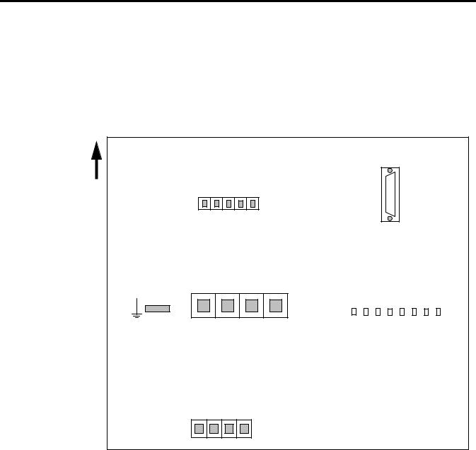
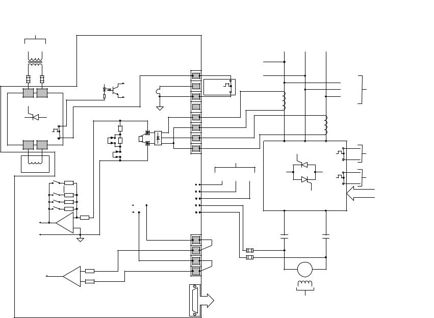
Terminal/Signal and Wiring
Diagrams
Use the diagram in Figure 3 - Stand Alone Regulator Terminal/Signal Block Diagram as a guide for the general location of and connection signals for the main input/output terminal blocks on the SAR. The diagram in Figure 4 on page 19 represents the recommended wiring for a typical SAR interface to a S6R power module.
Figure 3 - Stand Alone Regulator Terminal/Signal Block Diagram
Bottom View
Front of Unit
AC / DC Feedback
“-” |
“+ ” |
A C In |
A C In |
A C In |
D , |
C , |
W, |
V , |
U , |
Connector
“KP”
Field Bridge, AC Input / DC Ouput
|
|
“+ ” |
“- ” |
In |
In |
O u t |
O u t |
A C |
A C |
D C |
D C |
V 1 , |
U 1 , |
C 1, |
D 1 , |
PE (GND)
Power Module Armature Feedback
|
“+ ” |
|
“-” |
ut + “C ”) |
A r m F dbk |
ut - “D ”) |
A rm F d bk |
(P M O |
M otor |
( P M O |
Mo to r |
1A1 |
A1 |
1A2 |
A2 |
Connector
“KA”
Gate Output
Connector
“KPT11”
Power Module Thermal / CT Feedback
|
+ V therm , +15 V |
IS O C om |
Therm C om |
( Not U sed) |
C T1 + |
C T1 - |
C T2 + |
C T2 - |
||||||||||||||||
Connector |
1 |
2 |
3 |
4 |
5 |
6 |
7 |
8 |
||||||||||||||||
“KPT31” |
|
|
|
|
|
|
|
|
|
|
|
|
|
|
|
|
|
|
|
|
|
|
|
|
|
|
|
|
|
|
|
|
|
|
|
|
|
|
|
|
|
|
|
|
|
|
|
|
|
18 |
Rockwell Automation Publication 23P-UM001D-EN-P - July 2012 |
From Incoming AC Line
|
Transformer |
U |
V |
|
(External to SAR) |
|
|
|
See page 21 for |
|
|
|
Fuse Sizes |
|
|
|
(External to SAR) |
|
|
|
|
U1 |
V1 |
Rockwell |
Field Regulator (2 Quad) |
||
|
|
|
|
Automation |
|
C1 |
D1 |
|
|
Field PM Therm |
|
-UM001D-23PPublication |
|
+ |
- |
|
Motor Field |
||
|
|
||
P-EN |
|
|
|
- |
|
Current |
|
July |
|
|
|
2012 |
|
Armature |
|
|
Feedback |
|
|
|
|
|
|
Armature
Voltage
Feedback
19
Stand Alone Regulator (SAR)
Pwr Mod Thermal / CT Feedback
|
|
|
Conn “KPT31” |
|
|
|
+V_Therm, +15V |
1 |
|
+15 V ISO |
|
|
|
|
|
|
ISO_Com |
|
|
|
|
#S2 |
2 |
|
|
OT |
|
||
|
(Test |
Therm_Com |
|
|
|
|
3 |
||
|
|
Pt.) |
||
|
|
|
||
|
|
|
(Not_Used) |
4 |
|
|
0V ISO |
CT1 + |
5 |
|
|
|
|
|
|
2.5 |
|
CT1 - |
6 |
|
Ohms |
|
|
|
|
|
|
|
|
J4 |
2.5 |
XCT |
CT2 + |
7 |
|
||||
Ohms |
Ext. |
CT2 - |
|
|
|
|
|||
|
|
8 |
||
|
|
Rb |
|
|
J5 |
|
|
|
|
|
|
|
|
|
|
|
|
|
|
|
|
|
|
AC / DC Feedback |
|||
|
|
Internal Fuses |
Conn “KP” |
|||||||||
|
|
U, AC_In |
|
|
|
|||||||
|
|
|
|
|
|
|
|
|
|
|
|
|
|
|
|
|
|
|
|
|
|
V, AC_In |
|
|
|
|
|
|
|
|
|
|
|
|
|
|
|
|
|
|
|
|
|
|
|
|
|
W, AC_In |
|
|
|
|
|
|
|
|
|
|
|
|
|
|
|
|
|
|
|
|
|
|
|
|
|
|
|
|
|
|
To Voltage |
|
|
|
|
|
|
|
C, “+” |
|
|
|
|
|
|
|
|
|
|
|
|
|
|
||
|
Feedback |
|
|
|
|
|
|
|
D, “-” |
|
|
|
|
|
|
|
|
|
|
|
|
|
|||
|
|
|
|
|
|
|
|
|
|
|
||
|
Circuits |
|
|
|
|
|
|
|
|
|
|
|
|
|
|
|
|
|
|
|
|
|
|
||
|
|
|
|
|
|
|
|
|
|
|
|
|
|
|
|
|
|
|
|
|
|
|
|
|
|
Pwr Mod / Arm Fdbk
Conn “KA”
(PM Out + “C”) 1A1
Motor Arm Fdbk “+” A1
(PM Out - “D”) 1A2
Motor Arm Fdbk “-” A2
Gate Output
Conn “KPT11”
Incoming AC Line
To Field Power |
|
|
|
|
|
|
|
|
|
|
U |
V |
W |
|
|||
Module |
|
|
|
|||||
|
|
(L1) |
(L2) |
(L3) |
||||
Transformer |
|
|
||||||
|
|
|
|
|
|
|
||
|
|
|
|
|
|
|
|
|
|
|
|
|
|
|
|
|
|
|
|
|
|
|
|
|
|
|
|
|
|
|
|
|
|
|
|
Therm |
|
|
|
|
|
U, (L1) |
|
Fault |
|
|
|
|
|
V, (L2) |
To SAR |
On Pwr Mod |
|
|
|
|
|
Conn “KP” |
|
|
|
|
|
|
W, (L3) |
||
|
|
CT1 |
|
|
|
|
|
|
|
|
|
|
|
|
|
|
|
|
|
|
CT2 |
|
|
|
|
|
U |
V |
W |
|
To SAR |
|
|
|
|
|
Fault |
|
|
From AC Line Above |
|
|
|
Conn “KPT31” |
|||
|
|
|
|
||||
U |
V |
W |
|
|
Warning |
|
To Digital I/O |
(L1) |
(L2) |
(L3) |
|
|
|
||
|
|
|
(if available) |
||||
|
|
|
|
|
|
|
|
|
|
|
|
|
Gate Input |
|
Gates |
|
|
|
“+” |
|
“-” |
|
From Gate |
|
|
|
C |
|
D |
|
|
|
|
|
|
|
Amplifier Output |
||
|
|
|
|
|
|
|
|
|
|
|
|
|
|
|
(refer to gate |
|
|
|
|
|
|
|
wiring diagrams) |
*(See |
|
M |
|
|
M |
|
|
|
|
|
|
|
|
|
|
Note) |
|
5A, 700V |
|
|
|
|
|
|
|
5A, 700V |
|
|
|
|
|
*(See |
|
|
|
|
|
|
|
Note) |
|
|
|
M |
|
|
|
|
|
|
|
|
|
|
|
|
|
Motor Field |
|
|
|
||
To Gate Amplifier |
|
Supplied by SAR |
* Note: Armature Voltage |
||||
(refer to gate wiring |
Field Power Module |
Feedback. Jumpers |
|||||
diagrams) |
|
(or separately excited) |
must always be in place. |
||||
|
|
|
|
|
|||
Interface Regulator Alone Stand Typical - 4 Figure |
Installation, Regulator Alone Stand |
Module Power S6R to |
Configuration and Wiring |
|
2 Chapter |
Chapter 2 Stand Alone Regulator Installation, Wiring and Configuration
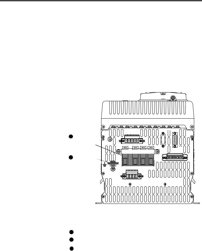
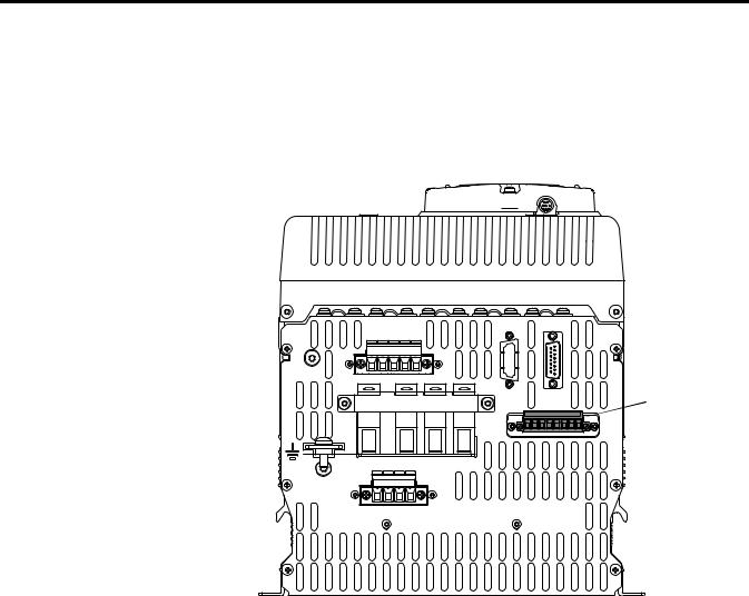
Field Power Module Bridge
and Ground Wiring
The SAR contains a two quadrant field power module bridge. The field bridge input circuit is rated for 100VAC…460VAC, ±10%, 50/60 Hz. The input and output connections to/from the field bridge are on the bottom of the SAR as shown.
An external transformer with appropriate primary fusing is required to supply the field. External fusing is also required at the input terminals V1 and U1 to protect the field bridge. The recommended fuse types are shown in the Table 4 on
page 21.
The SAR motor field current must configured with a hardware DIP switch and in firmware. See SAR Motor Field Current Configuration on page 26 for more information.
Figure 5 - Field Power Module Bridge Terminal Block and Ground Connection
Bottom View of SAR
1Field Power Module Bridge Terminal Block
2PE Terminal
PE
D C W V U |
V1 U1 C1 D1
1A1 (C)A1 1A2 (D)A2 |
KPT21  KPT11
KPT11
KPT31 

1 |
2 |
3 |
4 |
5 |
6 |
7 |
8 |
Table 3 - Field Power Module Bridge and Ground Terminal Specifications
|
|
|
Wire Size Range |
|
Recommended |
No. |
Terminal |
Description |
Maximum |
Minimum |
Torque |
1 |
V1, U1 |
AC Input Power |
25.0 mm2 |
10.0 mm2 |
4.0…4.5 N•m |
|
|
||||
1 |
C1, D1 |
DC Output Power |
(2 AWG) |
(10 AWG) |
(35.4…39.8 lb•in) |
|
to Motor Field |
|
|
|
|
2 |
PE |
Safety Ground (1) |
16.0 mm2 |
10.0 mm2 |
6.0…8.0 N•m |
|
|
(6 AWG) |
(8 AWG) |
(53.1…70.8 lb•in) |
|
|
|
|
(1) See Safety Ground (PE) on page 21 for more information.
20 |
Rockwell Automation Publication 23P-UM001D-EN-P - July 2012 |
Stand Alone Regulator Installation, Wiring and Configuration |
Chapter 2 |
|
|
Table 4 - Recommended Field Power Module Bridge Input Fuses
SAR Field |
Fuse Type: |
|
|
|
|
|
|
Bridge Rating |
Bussmann |
Ferraz Shawmut |
Siba |
|
|
|
|
40 A |
FWP-50A22Fa |
A70QS50-22F |
5014006.50 |
|
|
|
|
70 A |
FWP-100A22Fa |
A70QS100-22F |
5014006.100 |
|
|
|
|
The recommended fuse holder is a Cooper-Bussman, CH222D or equivalent - to accommodate 22 mm x 58 mm fuses.
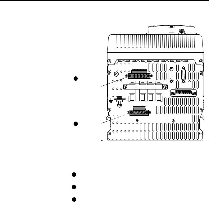
AC/DC Voltage and Motor
ArmatureVoltageFeedback
Wiring
Safety Ground (PE)
The Safety Ground - PE must be connected to system ground. Ground impedance must conform to the requirements of national and local industrial safety regulations and/or electrical codes. The integrity of all ground connections should be periodically checked.
For installations within a cabinet, a single safety ground point or ground bus bar connected directly to building steel should be used. All circuits should be grounded independently and directly to this point/bar.
The SAR requires AC feedback connections to connector KP (terminals U, V, and W) from the incoming line to monitor the incoming voltage level and establish the SCR gate firing sequence relative to the AC line. DC feedback connections to connector KP (terminals C and D) are required to monitor the voltage output from the DC power module. The combined information from the AC and DC feedback inputs is used to determine if the SCRs are firing properly. See Figure 4 on page 19 for recommended wiring for a typical SAR interface to S6R.
Fuses are required between the DC output power wiring on the DC power module to connector KP on the SAR. This will limit the current to the regulator in the event of an internal fault in the SAR. The recommended fuse types are shown in DC Feedback Fusing Requirements on page 22.
Rockwell Automation Publication 23P-UM001D-EN-P - July 2012 |
21 |
Chapter 2 Stand Alone Regulator Installation, Wiring and Configuration
Figure 6 - AC /DC Voltage Feedback (KP) and Motor Armature Voltage Feedback
(KA) Terminal Blocks
Bottom View of SAR
|
|
D |
C |
W V U |
|
|
1 |
AC /DC Voltage |
|
|
|
|
|
|
Feedback (KP) |
V1 |
|
U1 |
C1 |
D1 |
|
Terminal Block |
|
PE
1A1 (C)A1 1A2 (D)A2 |
2 Motor Armature
Voltage Feedback
(KA) Terminal
Block
KPT21  KPT11
KPT11
KPT31 

1 |
2 |
3 |
4 |
5 |
6 |
7 |
8 |
Table 5 - AC / DC Voltage and Motor Armature Voltage Feedback Terminal Specifications
|
|
|
Wire Size Range |
|
Recommended |
No. |
Terminal |
Description |
Maximum |
Minimum |
Torque |
1 |
W, V, U |
AC Input |
|
|
|
|
Feedback |
|
|
|
|
|
|
(connector KP) |
|
|
|
|
D, C |
DC Output |
2 |
2 |
|
1 |
|
Feedback |
6.0 mm |
0.2 mm |
0.7…0.8 N•m |
|
|
(connector KP) |
(10 AWG) |
(24 AWG) |
(6.2…7.1 lb•in) |
|
|
|
|
|
|
2 |
1A1, A1, |
Motor Armature |
|
|
|
1A2, A2 |
Voltage Feedback |
|
|
|
|
|
|
(connector KA) |
|
|
|
DC Feedback Fusing Requirements
The recommended fuses are:
•Bussmann fuse FWP-5A14F (5 A, 700V, Type FWP, 14 x 51mm), or equivalent.
Note: The AC voltage feedback inputs on the SAR are fused internally.
22 |
Rockwell Automation Publication 23P-UM001D-EN-P - July 2012 |

Stand Alone Regulator Installation, Wiring and Configuration |
Chapter 2 |
|
|
Connector KP Wiring
•Connect the motor armature terminal C to terminal C on connector KP
•Connect the motor armature terminal D to terminal D on connector KP
Connector KA Wiring
Connector KA must be wired to provide DC voltage feedback to the field regulator to control the field current based on the armature voltage. Terminal 1A1 is connected internally to terminal C (on connector KP) and terminal 1A2 is connected internally to terminal D (on connector KP). The default configuration is shown in Figure 7 and is wired as follows:
•Jumper terminal 1A1 to terminal A1
•Jumper terminal 1A2 to terminal A2
The jumpers will provide the field regulator with the power module/armature voltage feedback. This is the default wiring scheme for connector KA at the factory.
Figure 7 - Terminals on Connector KA Jumpered
1A1(C) A1 1A2 (D) A2
Place jumpers between terminals as shown
Rockwell Automation Publication 23P-UM001D-EN-P - July 2012 |
23 |
Chapter 2 Stand Alone Regulator Installation, Wiring and Configuration
Power Module Thermal
Switch and Current
Transformer Wiring
Connector KPT31 is used for power module thermal switch monitoring and current feedback via current transformer connections. Note that the thermal monitor circuit includes a thermal switch on the field power module within the SAR.
Figure 8 - Power Module Thermal Switch and Current Transformer Terminal Block (KPT31)
Bottom View of SAR
|
|
|
|
KPT21 |
|
KPT11 |
|
|
|
D |
C |
W V U |
|
|
|
|
|
|
|
|
|
|
|
|
|
|
|
|
Power Module |
V1 |
|
U1 |
C1 |
D1 |
|
KPT31 |
|
|
Thermal Switch and |
|
|
|
|
Current Transformer |
|||||
|
|
|
|
1 |
2 |
3 4 5 6 |
7 |
8 |
|
|
|
|
|
|
|
|
|
|
(KPT31) Terminal |
|
|
|
|
|
|
|
|
|
Block |
PE
1A1 (C)A1 1A2 (D)A2 |
Table 6 - Power Module Thermal Switch and Current Transformer Terminal
Specifications
|
|
|
Wire Size Range |
Recommended |
|
Terminal |
Description |
Maximum |
Minimum |
Torque |
|
1, 2, |
3 |
Thermal Switch Monitor(1) |
2.5 mm2 |
0.2 mm2 |
0.5…0.6 N•m |
5, 6, |
7, 8 |
Current Transformer Feedback |
(12 AWG) |
(24 AWG) |
(4.4…5.3 lb•in) |
(1)These terminals are jumpered by default. The jumper wires must remain in place if a power module thermal switch is NOT connected.
Current Transformer Connections
Current transformer 1 (CT1) monitors the U phase, with the “+” output of CT1 connected to terminal 5 of KPT31 and the “-” output of CT1 connected to terminal 6 of KPT31.
Current transformer 2 (CT2) monitors the W phase, with the “+” output of CT2 connected to terminal 7 of KPT31 and the “-” output of CT2 connected to terminal 8 of KPT31.
The “-” side of the CTs are connected together internally in the SAR.
24 |
Rockwell Automation Publication 23P-UM001D-EN-P - July 2012 |
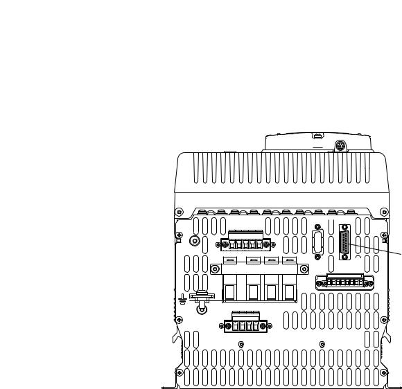
Stand Alone Regulator Installation, Wiring and Configuration |
Chapter 2 |
|
|
SAR Gate Output Cable
Connect the SAR gate output cable (23PAMP-Cx) to connector KPT11 on the SAR unit. The opposite end connects to the POWERFLEX DC SAR GATE INPUT on the Gate Amplifier. See Chapter 3 Gate Amplifier Installation and Wiring on page 41 for more information on Gate Amplifier installation and connections. See Cable Specifications on page 78 for information on available cable lengths for the 23PAMP-Cx cable.
Figure 9 - SAR Gate Output Cable Connection (KPT11)
Bottom View of SAR
PE
D C W V U |
V1 U1 C1 D1
1A1 (C)A1 1A2 (D)A2 |
KPT21  KPT11
KPT11
KPT31 

1 |
2 |
3 |
4 |
5 |
6 |
7 |
8 |
 SAR Gate Output
Cable (KPT11)
Connector
Control Circuit Power
Wiring
The control circuit for the SAR (not identified in the drawings contained in this manual) must be powered by an external 230V AC or 115V AC, single phase power supply. This power supply provides power for the SAR cooling fans and a HIM, communication adapter, I/O, encoder, or DC analog tachometer (if installed). See “Control Circuit Input Power” in the PowerFlex Digital DC Drive User Manual, publication 20P-UM001 for details.
In addition, the control circuit power input terminals require short circuit protection. See “Control Power Protection” in the PowerFlex Digital DC Drive User Manual, publication 20P-UM001 for details.
Rockwell Automation Publication 23P-UM001D-EN-P - July 2012 |
25 |

Chapter 2 Stand Alone Regulator Installation, Wiring and Configuration
SAR Motor Field Current
Configuration
Relay Output and Thermistor/Thermal Switch Wiring
Two normally open relay outputs and one motor thermistor (PTC) or thermal switch input are available for use and must be configured with the appropriate parameters. See “Relay Outputs” and “Thermistors and Thermal Switches” in the PowerFlex Digital DC Drive User Manual, publication 20P-UM001 for details.
I/O, Digital Encoder, and DC Analog Tachometer Wiring
The following standard I/O and feedback options are available with the SAR.
•Eight digital inputs, four digital outputs, three analog inputs, and two analog outputs are available. Additional digital and analog I/O is available when using the optional I/O expansion circuit board.
•An input terminal block is available for an incremental, dual channel, two channel optional (with jumper), differential (recommended) or singleended encoder with an input voltage configurable for +2.5V…5.2V or +5.4V…15.2V.
•An input terminal block is available for a DC analog tachometer with a maximum input voltage of 22.7V, 45.4V, 90.7V, 181.6V, or 302.9V and an input current of 8 mA full scale.
See “I/O Wiring” in the PowerFlex Digital DC Drive User Manual, publication 20P-UM001 for details.
Resolver Feedback Option Module Wiring
A resolver feedback module is available for purchase separately from the SAR. The resolver feedback option module includes the PowerFlex DC Drive Resolver Feedback Option Module Installation Instructions, publication 20P-IN071. See the PowerFlex Digital DC Drive User Manual, publication 20P-UM001 for resolver configuration details.
The SAR motor field current must be configured with both a hardware DIP switch (S14) and by setting parameter 374 [Drv Fld Brdg Cur] to the appropriate value. For each field current rating, in this case 40 and 70 A, there are several ranges to choose from with regard to the maximum range of the field current. The lowest range that is greater than the maximum motor field current should be selected to ensure the best resolution. See “Field Current Configuration” in the PowerFlex Digital DC Drive User Manual, publication 20P-UM001 for instructions.
26 |
Rockwell Automation Publication 23P-UM001D-EN-P - July 2012 |
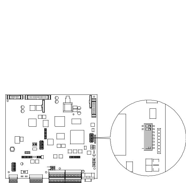
Stand Alone Regulator Installation, Wiring and Configuration |
Chapter 2 |
|
|
SAR Sizing
DIP switch S15 is configured for the appropriate SAR size at the factory. Do not change the settings unless you are installing a replacement control board.
Table 7 - SAR DIP Switch S15 Settings
Description |
S15-1 |
S15-2 |
S15-3 |
S15-4 |
S15-5 |
S15-6 |
S15-7 |
S15-8 |
|
|
|
|
|
|
|
|
|
SAR 200V |
Off |
Off |
Off |
Off |
Off |
On |
Off |
Off |
(230V) |
|
|
|
|
|
|
|
|
|
|
|
|
|
|
|
|
|
SAR 400V |
Off |
Off |
Off |
Off |
Off |
On |
On |
Off |
(460V) |
|
|
|
|
|
|
|
|
|
|
|
|
|
|
|
|
|
SAR 600V |
Off |
Off |
Off |
Off |
Off |
On |
Off |
On |
(575V) |
|
|
|
|
|
|
|
|
|
|
|
|
|
|
|
|
|
SAR 690V |
Off |
Off |
Off |
Off |
Off |
On |
On |
On |
(690V) |
|
|
|
|
|
|
|
|
|
|
|
|
|
|
|
|
|
Figure 10 - DIP Switch S15 Location on Control Board
|
|
|
|
|
|
|
XR |
|
|
|
|
|
|
|
|
|
XA |
|
|
|
|
|
|
|
|
|
|
|
|
|
|
||
|
|
|
|
|
|
|
|
|
|
|
|
|
|
|
|
S15 |
|
|
|
|
|
|
|
|
|
|
|
|
|
|
|
|
1 |
|
|
|
|
|
|
|
|
|
|
|
|
|
|
|
|
2 |
|
|
|
|
|
|
|
|
|
|
|
|
|
|
|
|
3 |
|
|
|
|
|
|
|
|
|
|
|
|
|
|
|
|
4 |
|
|
|
|
|
|
|
|
|
|
|
|
|
|
|
|
5 |
|
|
|
|
|
|
|
|
|
|
|
|
|
|
|
|
6 |
|
|
|
|
|
LA LB |
1 |
|
|
|
|
|
|
|
|
|
8 7 |
|
|
|
|
|
|
2 |
|
|
|
|
|
|
|
|
|
|
|
|
|
|
|
|
3 |
|
|
|
|
|
|
|
|
|
S3 |
|
|
|
|
|
|
4 |
|
|
|
|
|
|
|
|
|
|
|
|
|
|
|
|
5 |
|
|
|
|
|
|
|
|
|
|
|
|
|
|
|
|
6 |
|
|
|
|
|
|
|
|
|
S2 |
|
|
|
|
|
|
|
|
|
|
|
|
|
|
|
|
|
|
|
|
|
|
|
8 7 |
|
|
|
|
|
|
|
|
|
S1 |
|
|
|
|
|
XFCD |
S14 |
|
|
|
|
|
|
|
|
|
S0 |
|
|
|
|
|
|
|
|
|
|
|
|
|
|
|
||
|
|
|
|
|
|
|
|
|
|
|
|
|
|
|
|
|
|
|
|
|
|
S20 |
|
|
|
|
|
|
|
|
|
|
|
|
|
1 |
|
|
|
|
|
|
|
|
|
|
|
|
|
|
|
|
2 |
|
|
|
|
|
ON |
|
|
|
|
|
|
|
|
|
|
3 |
|
|
|
|
|
|
|
|
|
|
|
|
||
|
|
5 4 |
|
|
|
S11 |
|
|
|
|
|
|
|
|
||
S4 |
|
|
|
|
|
|
|
|
|
|
|
|
|
|||
|
|
6 |
|
|
|
S10 |
|
|
|
|
|
|
|
|
|
|
|
|
7 |
|
S21 |
|
S9 |
|
|
|
|
|
|
|
|
|
|
|
|
8 |
|
|
|
|
|
|
|
|
|
|
|
|
||
|
|
|
|
|
|
21 22 23 24 25 26 27 28 29 30 |
31 32 33 34 35 36 37 38 39 40 |
|
||||||||
- |
A |
B |
C + |
ENC_5 ENC_12 |
A+ A- B+ B- Z+ Z- COM +V |
21 22 23 24 25 26 27 28 29 30 |
31 32 33 34 35 36 37 38 39 40 |
DEBUG |
||||||||
1 |
2 |
3 |
4 |
5 |
6 |
7 |
8 |
9 10 |
11 12 13 14 15 16 17 18 19 20 |
|
||||||
|
|
|
|
|
|
|
||||||||||
- |
A |
B |
C + |
|
A+ A- B+ B- Z+ Z- COM +V |
1 |
2 |
3 |
4 |
5 |
6 |
7 |
8 |
9 10 |
11 12 13 14 15 16 17 18 19 20 |
|
|
|
|
|
|
|
|
||||||||||
S15
 8 7 6 5 4 3 2 1

S3
RST S2 

 ACT
ACT
S1 
 RUN PWR
S0
Rockwell Automation Publication 23P-UM001D-EN-P - July 2012 |
27 |
Loading...