


 Loading...
User Manual
PowerFlex 755 Drive Embedded EtherNet/IP Adapter
Firmware Release Number 1.xxx (or later)

Important User Information
Read this document and the documents listed in the additional resources section about installation, configuration, and operation of this equipment before you install, configure, operate, or maintain this product. Users are required to familiarize themselves with installation and wiring instructions in addition to requirements of all applicable codes, laws, and standards.
Activities including installation, adjustments, putting into service, use, assembly, disassembly, and maintenance are required to be carried out by suitably trained personnel in accordance with applicable code of practice.
If this equipment is used in a manner not specified by the manufacturer, the protection provided by the equipment may be impaired.
In no event will Rockwell Automation, Inc. be responsible or liable for indirect or consequential damages resulting from the use or application of this equipment.
The examples and diagrams in this manual are included solely for illustrative purposes. Because of the many variables and requirements associated with any particular installation, Rockwell Automation, Inc. cannot assume responsibility or liability for actual use based on the examples and diagrams.
No patent liability is assumed by Rockwell Automation, Inc. with respect to use of information, circuits, equipment, or software described in this manual.
Reproduction of the contents of this manual, in whole or in part, without written permission of Rockwell Automation, Inc., is prohibited.
Throughout this manual, when necessary, we use notes to make you aware of safety considerations.
WARNING: Identifies information about practices or circumstances that can cause an explosion in a hazardous environment, which may lead to personal injury or death, property damage, or economic loss.
ATTENTION: Identifies information about practices or circumstances that can lead to personal injury or death, property damage, or economic loss. Attentions help you identify a hazard, avoid a hazard, and recognize the consequence.
IMPORTANT Identifies information that is critical for successful application and understanding of the product.
Labels may also be on or inside the equipment to provide specific precautions.
SHOCK HAZARD: Labels may be on or inside the equipment, for example, a drive or motor, to alert people that dangerous voltage may be present.
BURN HAZARD: Labels may be on or inside the equipment, for example, a drive or motor, to alert people that surfaces may reach dangerous temperatures.
ARC FLASH HAZARD: Labels may be on or inside the equipment, for example, a motor control center, to alert people to potential Arc Flash. Arc Flash will cause severe injury or death. Wear proper Personal Protective Equipment (PPE). Follow ALL Regulatory requirements for safe work practices and for Personal Protective Equipment (PPE).
Allen-Bradley, Rockwell Software, and Rockwell Automation are trademarks of Rockwell Automation, Inc. Trademarks not belonging to Rockwell Automation are property of their respective companies.

Summary of Changes
New and Updated
Information
This manual contains new and updated information.
This table contains the changes made to this revision.
Topic |
Page |
|
|
|
|
Added information about the Connected Components Workbench software tool. |
Throughout |
|
|
manual |
|
Removed information for PLC-5, SLC 500, and MicroLogix 1100/1400 controllers. This information is now |
||
|
||
provided in a separate document titled ‘Controller Examples for EtherNet/IP Network Communications |
|
|
with PowerFlex 750-Series Drives’, publication 750COM-AT001. |
|
|
|
|
|
In Chapter 1 in the subsection ‘User-Supplied Equipment’ under configuration tool, added Connected |
14 |
|
Components Workbench software, a free configuration tool. |
|
|
|
|
|
In Chapter 4 in the ‘Using Automatic Device Configuration (ADC) with RSLogix 5000 Software, Version |
59 |
|
20.00 or Later” subsection, added new information to the introduction, along with a new Important |
|
|
statement and a new Tip. |
|
|
|
|
Rockwell Automation Publication 750COM-UM001E-EN-P - October 2013 |
3 |

Summary of Changes
Notes:
4 |
Rockwell Automation Publication 750COM-UM001E-EN-P - October 2013 |

|
|
Table of Contents |
Preface |
Conventions Used in This Manual . . . . . . . . . . . . . . . . . . |
. . . . . . . . . . . . . . . 9 |
|
Rockwell Automation Support . . . . . . . . . . . . . . . . . . . . . . |
. . . . . . . . . . . . . . . 9 |
|
Additional Resources . . . . . . . . . . . . . . . . . . . . . . . . . . . . . . . |
. . . . . . . . . . . . . . 10 |
|
Chapter 1 |
|
Getting Started |
Components. . . . . . . . . . . . . . . . . . . . . . . . . . . . . . . . . . . . . . . |
. . . . . . . . . . . . . . 11 |
|
Features . . . . . . . . . . . . . . . . . . . . . . . . . . . . . . . . . . . . . . . . . . . |
. . . . . . . . . . . . . . 12 |
|
Compatible Products . . . . . . . . . . . . . . . . . . . . . . . . . . . . . . . |
. . . . . . . . . . . . . . 13 |
|
Required Equipment . . . . . . . . . . . . . . . . . . . . . . . . . . . . . . . |
. . . . . . . . . . . . . . 13 |
|
Safety Precautions . . . . . . . . . . . . . . . . . . . . . . . . . . . . . . . . . . |
. . . . . . . . . . . . . . 15 |
|
Quick Start . . . . . . . . . . . . . . . . . . . . . . . . . . . . . . . . . . . . . . . . |
. . . . . . . . . . . . . . 16 |
|
Chapter 2 |
|
Installing the Adapter |
Preparing for an Installation. . . . . . . . . . . . . . . . . . . . . . . . . |
. . . . . . . . . . . . . . 17 |
|
Setting the IP Address . . . . . . . . . . . . . . . . . . . . . . . . . . . . . . |
. . . . . . . . . . . . . . 18 |
|
Connecting the Adapter to the Network . . . . . . . . . . . . . |
. . . . . . . . . . . . . . 20 |
|
Applying Power . . . . . . . . . . . . . . . . . . . . . . . . . . . . . . . . . . . . |
. . . . . . . . . . . . . . 21 |
|
Commissioning the Adapter . . . . . . . . . . . . . . . . . . . . . . . . |
. . . . . . . . . . . . . . 24 |
|
Chapter 3 |
|
Configuring the Adapter |
Configuration Tools. . . . . . . . . . . . . . . . . . . . . . . . . . . . . . . . |
. . . . . . . . . . . . . . 25 |
|
Using the PowerFlex 20-HIM-A6 or 20-HIM-C6S HIM to Access |
|
|
Parameters. . . . . . . . . . . . . . . . . . . . . . . . . . . . . . . . . . . . . . |
. . . . . . . . . . . . . . 26 |
|
Setting the Adapter IP Address . . . . . . . . . . . . . . . . . . . . . . |
. . . . . . . . . . . . . . 26 |
|
Setting the Data Rate . . . . . . . . . . . . . . . . . . . . . . . . . . . . . . . . |
. . . . . . . . . . . . . 31 |
|
Selecting Master-Slave or Peer-to-Peer Hierarchy . . . . . . |
. . . . . . . . . . . . . 32 |
|
Setting a Fault Action . . . . . . . . . . . . . . . . . . . . . . . . . . . . . . . |
. . . . . . . . . . . . . 38 |
|
Setting Web Access Control . . . . . . . . . . . . . . . . . . . . . . . . . |
. . . . . . . . . . . . . 40 |
|
Resetting the Adapter . . . . . . . . . . . . . . . . . . . . . . . . . . . . . . . |
. . . . . . . . . . . . . 41 |
|
Restoring Adapter Parameters to Factory Defaults . . . . . |
. . . . . . . . . . . . . 41 |
|
Viewing the Adapter Status Using Parameters . . . . . . . . . |
. . . . . . . . . . . . . 42 |
|
Updating the Adapter Firmware. . . . . . . . . . . . . . . . . . . . . . |
. . . . . . . . . . . . . 43 |
|
Chapter 4 |
|
Configuring the I/O |
Using RSLinx Classic . . . . . . . . . . . . . . . . . . . . . . . . . . . . . . . . |
. . . . . . . . . . . . . 45 |
|
ControlLogix Example . . . . . . . . . . . . . . . . . . . . . . . . . . . . . . |
. . . . . . . . . . . . . 46 |
Rockwell Automation Publication 750COM-UM001E-EN-P - October 2013 |
5 |

Table of Contents |
|
|
|
Chapter 5 |
|
Using the I/O |
About I/O Messaging . . . . . . . . . . . . . . . . . . . . . . . . . . . . . . . . . . . . . . . . . . . . |
79 |
|
Understanding the ControlLogix Controller I/O Image. . . . . . . . . . . . . |
80 |
|
Using Logic Command/Status . . . . . . . . . . . . . . . . . . . . . . . . . . . . . . . . . . . . |
81 |
|
Using Reference/Feedback . . . . . . . . . . . . . . . . . . . . . . . . . . . . . . . . . . . . . . . . |
81 |
|
Using Datalinks . . . . . . . . . . . . . . . . . . . . . . . . . . . . . . . . . . . . . . . . . . . . . . . . . . |
82 |
|
Example Ladder Logic Program Information . . . . . . . . . . . . . . . . . . . . . . . |
83 |
|
ControlLogix Controller Example . . . . . . . . . . . . . . . . . . . . . . . . . . . . . . . . . |
84 |
|
Chapter 6 |
|
Using Explicit Messaging |
About Explicit Messaging . . . . . . . . . . . . . . . . . . . . . . . . . . . . . . . . . . . . . . . . . |
92 |
|
Performing Explicit Messaging . . . . . . . . . . . . . . . . . . . . . . . . . . . . . . . . . . . . |
93 |
|
ControlLogix Controller Examples . . . . . . . . . . . . . . . . . . . . . . . . . . . . . . . . |
94 |
|
Chapter 7 |
|
Troubleshooting |
Understanding the Status Indicators . . . . . . . . . . . . . . . . . . . . . . . . . . . . . . |
107 |
|
ENET Status Indicator . . . . . . . . . . . . . . . . . . . . . . . . . . . . . . . . . . . . . . . . . . |
108 |
|
LINK Status Indicator. . . . . . . . . . . . . . . . . . . . . . . . . . . . . . . . . . . . . . . . . . . |
108 |
|
Viewing Adapter Diagnostic Items. . . . . . . . . . . . . . . . . . . . . . . . . . . . . . . . |
109 |
|
Viewing and Clearing Events . . . . . . . . . . . . . . . . . . . . . . . . . . . . . . . . . . . . . |
111 |
|
Chapter 8 |
|
Viewing the Adapter Web Pages |
Enabling the Adapter Web Pages . . . . . . . . . . . . . . . . . . . . . . . . . . . . . . . . . |
113 |
|
Viewing the Web Pages . . . . . . . . . . . . . . . . . . . . . . . . . . . . . . . . . . . . . . . . . . |
113 |
|
Process Display Pop-up Dialog Box . . . . . . . . . . . . . . . . . . . . . . . . . . . . . . . |
116 |
|
TCP/IP Configuration Web Page . . . . . . . . . . . . . . . . . . . . . . . . . . . . . . . . |
117 |
|
Configure E-mail Notification Web Page. . . . . . . . . . . . . . . . . . . . . . . . . . |
118 |
|
Device Information Pages . . . . . . . . . . . . . . . . . . . . . . . . . . . . . . . . . . . . . . . . |
121 |
|
Appendix A |
|
Specifications |
Communications. . . . . . . . . . . . . . . . . . . . . . . . . . . . . . . . . . . . . . . . . . . . . . . . |
125 |
|
Regulatory Compliance . . . . . . . . . . . . . . . . . . . . . . . . . . . . . . . . . . . . . . . . . . |
125 |
|
Appendix B |
|
Adapter Parameters |
How Parameters Are Organized . . . . . . . . . . . . . . . . . . . . . . . . . . . . . . . . . . |
127 |
|
Parameter List . . . . . . . . . . . . . . . . . . . . . . . . . . . . . . . . . . . . . . . . . . . . . . . . . . |
128 |
6 |
Rockwell Automation Publication 750COM-UM001E-EN-P - October 2013 |

|
|
Table of Contents |
|
Appendix C |
|
EtherNet/IP Objects |
Supported Data Types . . . . . . . . . . . . . . . . . . . . . . . . . . . . . . . . . . . . |
. . . . . . . 137 |
|
Identity Object. . . . . . . . . . . . . . . . . . . . . . . . . . . . . . . . . . . . . . . . . . . . |
. . . . . . 138 |
|
Assembly Object . . . . . . . . . . . . . . . . . . . . . . . . . . . . . . . . . . . . . . . . . . |
. . . . . . 139 |
|
Register Object. . . . . . . . . . . . . . . . . . . . . . . . . . . . . . . . . . . . . . . . . . . . |
. . . . . . 140 |
|
PCCC Object . . . . . . . . . . . . . . . . . . . . . . . . . . . . . . . . . . . . . . . . . . . . |
. . . . . . 141 |
|
DPI Device Object . . . . . . . . . . . . . . . . . . . . . . . . . . . . . . . . . . . . . . . . |
. . . . . . 145 |
|
DPI Parameter Object . . . . . . . . . . . . . . . . . . . . . . . . . . . . . . . . . . . . . |
. . . . . . 148 |
|
DPI Fault Object. . . . . . . . . . . . . . . . . . . . . . . . . . . . . . . . . . . . . . . . . . |
. . . . . . 154 |
|
DPI Alarm Object. . . . . . . . . . . . . . . . . . . . . . . . . . . . . . . . . . . . . . . . . |
. . . . . . 156 |
|
DPI Diagnostic Object . . . . . . . . . . . . . . . . . . . . . . . . . . . . . . . . . . . . |
. . . . . . 158 |
|
DPI Time Object . . . . . . . . . . . . . . . . . . . . . . . . . . . . . . . . . . . . . . . . . |
. . . . . . 160 |
|
Host DPI Parameter Object. . . . . . . . . . . . . . . . . . . . . . . . . . . . . . . . |
. . . . . . 162 |
|
TCP/IP Interface Object . . . . . . . . . . . . . . . . . . . . . . . . . . . . . . . . . . |
. . . . . . 168 |
|
Ethernet Link Object . . . . . . . . . . . . . . . . . . . . . . . . . . . . . . . . . . . . . . |
. . . . . . 170 |
|
Appendix D |
|
Logic Command/Status Words: |
Logic Command Word . . . . . . . . . . . . . . . . . . . . . . . . . . . . . . . . . . . . |
. . . . . . 173 |
PowerFlex 750-Series Drives |
Logic Status Word . . . . . . . . . . . . . . . . . . . . . . . . . . . . . . . . . . . . . . . . |
. . . . . . 174 |
|
Appendix E |
|
History of Changes |
750COM-UM001D-EN-P, February 2012 . . . . . . . . . . . . . . . . . |
. . . . . . 175 |
|
750COM-UM001C-EN-P, November 2011 . . . . . . . . . . . . . . . . |
. . . . . . 176 |
|
750COM-UM001B-EN-P, October 2011 . . . . . . . . . . . . . . . . . . |
. . . . . . 176 |
|
750COM-UM001A-EN-P, January 2009 . . . . . . . . . . . . . . . . . . . |
. . . . . . 176 |
|
Glossary |
|
|
Index |
|
Rockwell Automation Publication 750COM-UM001E-EN-P - October 2013 |
7 |

Table of Contents
8 |
Rockwell Automation Publication 750COM-UM001E-EN-P - October 2013 |

Preface
Conventions Used in This
Manual
Rockwell Automation
Support
This manual provides information about the EtherNet/IP adapter embedded on the Main Control Board in PowerFlex® 755 drives, and using it for network communication.
The following conventions are used throughout this manual:
•Parameter names are shown in the format Parameter xx - [*]. The xx represents the parameter number. The * represents the parameter name— for example Parameter 01 - [DL From Net Cfg 01].
•The drive firmware revision number (FRN) is displayed as FRN X.xxx, where ‘X’ is the major revision number and ‘xxx’ is the minor revision number.
•The dialog box images in this manual resulted from using the following software:
–RSLinx® Classic software, version 2.52
–RSLogix™ 5000 software, version 16.00 (for Automatic Device Configuration information only, RSLogix 5000, version 20.00)
Different versions of the software may have dialog boxes that vary in appearance, and differences in procedures.
Rockwell Automation offers support services worldwide, with over 75 sales and support offices, over 500 authorized distributors, and over 250 authorized systems integrators located through the United States alone. In addition, Rockwell Automation representatives are in every major country in the world.
Local Product Support
Contact your local Rockwell Automation representative for the following:
•Sales and order support
•Product technical training
•Warranty support
•Support service agreements
Technical Product Assistance
For technical assistance, please review the information in Chapter 7, Troubleshooting, first. If you still have problems, then access the Allen-Bradley Technical Support website at http://www.ab.com/support/abdrives or contact Rockwell Automation.
Rockwell Automation Publication 750COM-UM001E-EN-P - October 2013 |
9 |

Preface
Additional Resources
These documents contain additional information concerning related products from Rockwell Automation.
Resource |
Description |
|
|
|
|
EtherNet/IP Media Planning and Installation Manual, ODVA publication 148 (1) |
Information on the planning, installation, and techniques used to implement |
|
|
an EtherNet/IP network. |
|
EtherNet/IP Network Infrastructure Guidelines, ODVA Publication 35 (1) |
||
|
||
Ethernet Design Considerations Reference Manual, publication ENET-RM002 |
|
|
|
|
|
Connected Components Workbench website http://www.ab.com/support/abdrives/webupdate/ |
Information on the Connected Components Workbench™ software tool— |
|
software.html, and online help (2) |
and includes a link for free software download. |
|
DriveExplorer website http://www.ab.com/drives/driveexplorer, and online help (2) |
Information on using the DriveExplorer™ software tool. |
|
DriveExecutive website http://www.ab.com/drives/drivetools, and online help (2) |
Information on using the DriveExecutive™ software tool. |
|
PowerFlex 750-Series Drive Installation Instructions, publication 750-IN001 |
Information on installing, programming, and technical data of PowerFlex® |
|
|
750-Series Drives |
|
PowerFlex 750-Series Drive Programming Manual, publication 750-PM001 |
||
|
||
|
|
|
PowerFlex 750-Series Drive Technical Data, publication 750-TD001 |
|
|
|
|
|
PowerFlex 20-HIM-A6/-C6S HIM (Human Interface Module) User Manual, publication 20HIM-UM001 |
Information on the installation and use of PowerFlex 20-HIM-A6 or 20-HIM- |
|
|
C6S HIMs. |
|
|
|
|
Getting Results with RSLinx Guide, publication LINX-GR001, and online help (2) |
Information on using RSLinx Classic software. |
|
RSLogix 5000 PIDE Autotuner Getting Results Guide, publication PIDE-GR001, and online help (2) |
Information on using the RSLogix 5000 software tool. |
|
EtherNet/IP Modules in Logix5000 Control Systems User Manual, publication ENET-UM001 |
Information on using the ControlLogix® 1756-ENBT or 1756-EN2T |
|
|
communication modules with your Logix 5000 controller and communicating |
|
|
with various devices on the EtherNet/IP network. |
|
|
|
|
Controller Examples for EtherNet/IP Network Communications with PowerFlex 750-Series Drives, |
Information on using PLC-5®, SLC™ 500, and MicroLogix™ 1100/1400 |
|
publication 750COM-AT001 |
controllers with PowerFlex 750-Series drives that are equipped with a |
|
|
20-750-ENETR Dual-port EtherNet/IP option module or embedded EtherNet/ |
|
|
IP adapter (PowerFlex 755 drive only). |
|
|
|
(1)Use this link to the ODVA EtherNet/IP library: http://odva.org/Home/ODVATECHNOLOGIES/EtherNetIP/EtherNetIPLibrary/tabid/76/Default.aspx
(2)The online help is installed with the software.
You can view or download publications at http:// www.rockwellautomation.com/literature. To order paper copies of technical documentation, contact your local Rockwell Automation distributor or sales representative.
To find your local Rockwell Automation distributor or sales representative, visit
http://www.rockwellautomation.com/locations.
For information such as firmware updates or answers to drive-related questions, go to the Drives Service & Support web site at http://www.ab.com/support/ abdrives and click the Downloads or Knowledgebase link.
10 |
Rockwell Automation Publication 750COM-UM001E-EN-P - October 2013 |
Chapter 1
Getting Started
The EtherNet/IP adapter, embedded on the Main Control Board in PowerFlex 755 drives, is used for network communication.
Topic |
Page |
|
|
Components |
11 |
|
|
Features |
12 |
|
|
Compatible Products |
13 |
|
|
Required Equipment |
13 |
|
|
Safety Precautions |
15 |
|
|
Quick Start |
16 |
|
|
Components
Components shown with HIM bezel open and drive cover removed.
Drive Control Pod

4 |
5 |
|
3
2
1 |
0 |
|
|
4 |
5 |
|
|
3 |
|
2 |
|
1 |
0 |
|
|
4 |
5 |
|
|
3 |
|
2 |
|
1 |
0 |
|
Drive STS Indicator |
|
|
|
|
||
|
|
|
|
|
|
|
|
|
Item |
Part |
Description |
||
|
|
|
|
|||
|
|
|
|
|
Status |
Two LEDs that indicate the status |
|
|
|
|
|
Indicators |
of the adapter and network |
|
|
|
|
|
|
communication. See Chapter 7, |
|
|
|
|
|
|
Troubleshooting. |
|
|
|
|
|
|
|
|
|
|
|
|
IP Address |
Sets the IP address of the |
|
|
|
|
|
Switches |
embedded adapter when not |
|
|
|
|
|
|
using a BOOTP server or adapter |
|
|
|
|
parameters. See Setting the IP |
||
|
|
|
|
|
|
Address on page 18 for details. |
|
|
|
|
|
|
|
|
|
|
|
|
Ethernet |
An RJ-45 connector for the |
|
|
|
|
|
Connector |
Ethernet cable. The connector is |
|
|
|
|
|
|
CAT-5 compliant to ensure reliable |
|
|
|
|
|
|
data transfer on 100Base-TX |
|
|
|
|
|
Ethernet connections. |
|
|
|
|
|
|
|
|
6 |
|
|
|
|
DPI Port 2 |
Cable connection for handheld |
|
|
|
|
|
and remote options. |
|
7 |
|
|
|
|
|
|
8 |
|
|
|
|
|
|
|
|
|
|
|
|
|
|
|
|
|
|
|
|
9 |
|
|
|
|
|
|
6 |
|
|
|
|
|
|
|
|
|
|
|
|
|
7 |
|
|
|
|
|
|
8 |
|
|
|
|
|
|
9 |
|
|
|
|
|
|
6 |
|
|
|
|
|
|
|
|
|
|
|
|
|
7 |
|
|
|
|
|
|
8 |
|
|
|
|
|
|
9 |
|
|
|
|
|
|
Rockwell Automation Publication 750COM-UM001E-EN-P - October 2013 |
11 |

Chapter 1 |
Getting Started |
|
|
Features
The features of the embedded EtherNet/IP adapter include the following:
•Switches to set an IP address before applying power to the drive—or you can disable the switches and use a BOOTP (Bootstrap Protocol) server or adapter parameters to configure the IP address.
•Compatibility with the following configuration tools to configure the embedded EtherNet/IP adapter and host drive:
–PowerFlex 20-HIM-A6 or 20-HIM-C6S HIM (Human Interface Module) on the drive, if available
–Connected Components Workbench software, version1.02 or later
–DriveExplorer software, version 6.01 or later
–DriveExecutive software, version 5.01 or later.
•Status indicators that report the status of the embedded EtherNet/IP adapter and network communications. They are visible when the drive cover is open or closed.
•Parameter-configured 32-bit Datalinks in the I/O to meet application requirements (16 Datalinks to write data from the network to the drive, and 16 Datalinks to read data to the network from the drive).
•Explicit Messaging support.
•Master-Slave or Peer-to-Peer hierarchy that can be configured to transmit data to and from either a controller or another PowerFlex 750-Series drive on the network.
•Supports ‘Integrated Motion on the EtherNet/IP network’ operation for the PowerFlex 755 drive, firmware revision 2.003 or later. For details to set up ‘Integrated Motion on the EtherNet/IP network’ operation, see Integrated Motion on the EtherNet/IP Network User Manual, publication MOTION-UM003.
TIP |
For best reliability in ‘Integrated Motion on the EtherNet/IP network’ |
|
applications, we recommend that you always use Rockwell |
|
Automation Cat5e shielded Ethernet cable. |
•User-defined fault actions to determine how the embedded EtherNet/IP adapter and its host PowerFlex 755 drive respond to the following:
–I/O messaging communication disruptions (Comm Flt Action)
–Controllers in Idle mode (Idle Flt Action)
–Peer device communication disruptions (Peer Flt Action)
–Explicit messaging disruptions for drive control via PCCC, the CIP Register Object or the CIP Assembly Object (Msg Flt Action)
12 |
Rockwell Automation Publication 750COM-UM001E-EN-P - October 2013 |

Getting Started |
Chapter 1 |
|
|
Compatible Products
Required Equipment
•Automatic Device Configuration (ADC), which is an ‘RSLogix 5000 software, version 20.00, feature’ that supports the automatic download of configuration data. This occurs after the Logix controller establishes an EtherNet/IP network connection to a PowerFlex 755 drive (firmware revision 4.001 or later) and its associated peripherals.
•Web pages, viewed by using a web browser, that show information about the embedded EtherNet/IP adapter, its host drive, and DPI devices connected to the drive.
•Configured e-mail messaging to desired addresses when selected drive faults occur and/or are cleared, and/or when the embedded EtherNet/IP adapter takes a communication or idle fault action.
•Access to any PowerFlex drive and its connected peripherals on the network to which the embedded EtherNet/IP adapter is connected.
At the time of publication, the embedded EtherNet/IP adapter is compatible with Allen-Bradley PowerFlex 755 drives.
Some of the equipment that is required for use with the embedded EtherNet/IP adapter is shipped with the drive, but some you must supply yourself.
Equipment Shipped with the Drive
Since the EtherNet/IP adapter is embedded on the Main Control Board in the PowerFlex 755 drive, it is always an integral part of the drive and, therefore, does not require installation instructions.
User-Supplied Equipment
To configure the embedded EtherNet/IP adapter, you must supply the following:
A small screwdriver
Ethernet cable (for details, see the EtherNet/IP Media Planning and Installation Manual, ODVA publication 148 available on the ODVA website at http://odva.org/Home/ODVATECHNOLOGIES/ EtherNetIP/EtherNetIPLibrary/tabid/76/Default.aspx)
Ethernet switch (for details, see the Ethernet Design Considerations Reference Manual, publication ENET-RM002)
Rockwell Automation Publication 750COM-UM001E-EN-P - October 2013 |
13 |

Chapter 1 |
Getting Started |
|
|
Drive and embedded adapter configuration tool, such as the following:
–PowerFlex 20-HIM-A6 or 20-HIM-C6S HIM
–Connected Components Workbench software, version 1.02 or later
Connected Components Workbench is the recommended stand-alone software tool for use with PowerFlex drives. You can obtain a free copy by:
•Internet download at http://www.ab.com/support/abdrives/ webupdate/software.html
•Requesting a DVD at http://www.ab.com/onecontact/ controllers/micro800/
Your local distributor may also have copies of the DVD available.
Connected Components Workbench software cannot be used to configure SCANport-based drives or Bulletin 160 drives.
–DriveExplorer software, version 6.01 or later
This software tool has been discontinued and is now available as freeware at http://www.ab.com/support/abdrives/webupdate/ software.html. There are no plans to provide future updates to this tool and the download is being provided ‘as-is’ for users that lost their DriveExplorer CD, or need to configure legacy products not supported by Connected Components Workbench software.
–DriveExecutive software, version 5.01 or later
A Lite version of DriveExecutive software ships with RSLogix 5000, RSNetWorx MD, FactoryTalk AssetCentre, and ItelliCENTER software. All other versions are purchasable items:
•9303-4DTE01ENE Drive Executive software
•9303-4DTS01ENE DriveTools SP Suite (includes DriveExecutive and DriveObserver software)
•9303-4DTE2S01ENE DriveExecutive software upgrade to DriveTools SP Suite (adds DriveObserver software)
DriveExecutive software updates (patches, and so forth) can be obtained at http://www.ab.com/support/abdrives/webupdate/software.html. It is highly recommended that you periodically check for and install the latest update.
– BOOTP, version 2.1 or later, for network setup only
Controller configuration software, such as RSLogix 5000 software, version 20.00 and earlier, or Studio 5000™ Logix Designer application, version 21.00 and later
A computer connection to the EtherNet/IP network
14 |
Rockwell Automation Publication 750COM-UM001E-EN-P - October 2013 |
Getting Started |
Chapter 1 |
|
|
Safety Precautions
Please read the following safety precautions carefully.
ATTENTION: Risk of injury or equipment damage exists. Only personnel familiar with drive and power products and the associated machinery should plan or implement the installation, start up, configuration, and subsequent maintenance of the drive using this embedded adapter. Failure to comply may result in injury and/or equipment damage.
ATTENTION: Risk of equipment damage exists. The embedded adapter contains electrostatic discharge (ESD) sensitive parts that can be damaged if you do not follow ESD control procedures. Static control precautions are required when handling the adapter. If you are unfamiliar with static control procedures, see Guarding Against Electrostatic Damage, publication 8000-4.5.2.
ATTENTION: Risk of injury or equipment damage exists. If the adapter is transmitting control I/O to the drive, the drive may fault when you reset the adapter. Determine how your drive will respond before resetting the adapter.
ATTENTION: Risk of injury or equipment damage exists. Embedded adapter
Parameters 54 - [Comm Flt Action], 55 - [Idle Flt Action], 56 - [Peer Flt Action], and 57 - [Msg Flt Action] let you determine the action of the adapter and drive if I/O communication is disrupted, the controller is idle, peer I/O is disrupted, or explicit messaging for drive control is disrupted. By default, these parameters fault the drive. You may configure these parameters so that the drive continues to run, however, precautions should be taken to verify that the settings of these parameters do not create a risk of injury or equipment damage. When commissioning the drive, verify that your system responds correctly to various situations (for example, a disconnected cable or a controller in idle state).
ATTENTION: Risk of injury or equipment damage exists. When a system is configured for the first time, there may be unintended or incorrect machine motion. Disconnect the motor from the machine or process during initial system testing.
ATTENTION: Risk of injury or equipment damage exists. The examples in this publication are intended solely for purposes of example. There are many variables and requirements with any application. Rockwell Automation does not assume responsibility or liability (to include intellectual property liability) for actual use of the examples shown in this publication.
Rockwell Automation Publication 750COM-UM001E-EN-P - October 2013 |
15 |

Chapter 1 |
Getting Started |
|
|
Quick Start
This section is provided to help experienced users quickly start using the embedded EtherNet/IP adapter. If you are unsure how to complete a step, refer to the referenced chapter.
Step |
Action |
See |
|
|
|
|
|
1 |
Review the safety precautions for the adapter. |
Throughout this manual |
|
|
|
|
|
2 |
Verify that the PowerFlex drive is properly installed. |
PowerFlex 750-Series AC Drive |
|
|
|
|
Installation Instructions, |
|
|
|
publication 750-IN001 |
|
|
|
|
3 |
Set the adapter IP address. |
Chapter 2, |
|
|
|
a. When using the adapter switches, set the IP address now and |
Installing the Adapter |
|
|
|
|
|
|
proceed with step 4. |
|
|
|
When using a BOOTP server, or adapter parameters instead to set the |
|
|
|
IP address, first perform step 3b and 3c, and all of step 4. Then |
|
|
|
proceed with step 5. |
|
|
|
b. Verify that the PowerFlex drive is not powered. |
|
|
|
c. Connect the embedded EtherNet/IP adapter to the network with an |
|
|
|
Ethernet cable. |
|
|
|
|
|
4 |
Apply power to the drive. |
Chapter 2, |
|
|
|
a. Replace the drive cover or close the drive door. |
Installing the Adapter |
|
|
|
|
|
|
b. Apply power to the drive. |
|
|
|
The embedded EtherNet/IP adapter receives power from the drive. |
|
|
|
The status indicators should be green. If they flash red, there is a |
|
|
|
problem. See Chapter 7, Troubleshooting. |
|
|
|
c. Configure and verify key drive parameters. |
|
|
|
|
|
5 |
Configure the adapter for your application. |
Chapter 3, |
|
|
Set embedded EtherNet/IP adapter parameters for the following functions |
Configuring the Adapter |
|
|
|
||
|
as required by your application: |
|
|
|
• IP address, subnet mask, and gateway address (only when not using |
|
|
|
• |
adapter switches) |
|
|
Data rate |
|
|
|
• |
I/O configuration |
|
|
• Master-Slave or Peer-to-Peer hierarchy |
|
|
|
• |
Fault actions |
|
|
• Web enable and features |
|
|
|
|
|
|
6 |
Configure the controller to communicate with the adapter. |
Chapter 4, |
|
|
Use a controller configuration tool, such as RSLogix software, to configure |
Configuring the I/O |
|
|
|
||
|
the master on the network to recognize the embedded EtherNet/IP adapter |
|
|
|
and drive. |
|
|
|
|
|
|
7 |
Create a ladder logic program. |
Chapter 5, |
|
|
Use a controller configuration tool, such as RSLogix software, to create a |
Using the I/O |
|
|
Chapter 6, |
||
|
ladder logic program that enables you to do the following: |
||
|
• Control the drive, via the embedded EtherNet/IP adapter, by using I/O. |
Using Explicit Messaging |
|
|
|
||
|
• Monitor or configure the drive by using explicit messages. |
|
|
|
|
|
|
16 |
Rockwell Automation Publication 750COM-UM001E-EN-P - October 2013 |

Chapter 2
Installing the Adapter
Since the EtherNet/IP adapter is embedded on the Main Control Board in the PowerFlex 755 drive, the only required adapter installation is setting its IP address and connecting it to the network.
Topic |
Page |
|
|
Preparing for an Installation |
17 |
|
|
Setting the IP Address |
18 |
|
|
Connecting the Adapter to the Network |
20 |
|
|
Applying Power |
21 |
|
|
Commissioning the Adapter |
24 |
|
|
Preparing for an Installation Before installing the embedded EtherNet/IP adapter, do the following:
•Make sure the Ethernet switch is the correct type. A ‘managed’ switch that supports IGMP snooping is usually recommended. An ‘unmanaged’ switch can be used instead if RSLogix 5000 software, version 18.00 or later, is used and all devices on the network are configured for ‘unicast’ I/O. For more details, see the following documents:
–EtherNet/IP Media Planning and Installation Manual, ODVA publication 148
–EtherNet/IP Network Infrastructure Guidelines, ODVA publication 35
–Ethernet Design Considerations Reference Manual, publication ENET-RM002
•Understand IGMP Snooping/Ethernet Switches
The embedded EtherNet/IP adapter is a multicast device. In most situations, an IGMP snooping (managed) switch is required. If more than one or two embedded EtherNet/IP adapters are connected to the switch, a managed switch is required—otherwise the drive may fault on a Net IO Timeout network loss. The embedded EtherNet/IP adapter, RSLogix 5000 software version 18 or later, and a ControlLogix or CompactLogix controller will support unicast. Unicast setup is required when adding the drive to the I/O. When all embedded EtherNet/IP adapters are set up as unicast devices, then an IGMP snooping (managed) switch is not needed.
Much of EtherNet/IP implicit (I/O) messaging uses IP multicast to distribute I/O control data, which is consistent with the CIP producer/
Rockwell Automation Publication 750COM-UM001E-EN-P - October 2013 |
17 |

Chapter 2 Installing the Adapter
Setting the IP Address
consumer model. Historically, most switches have treated multicast packets the same as broadcast packets. That is, all multicast packets are retransmitted to all ports.
IGMP snooping constrains the flooding of multicast traffic by dynamically configuring switch ports so that multicast traffic is forwarded only to ports associated with a particular IP multicast group.
Switches that support IGMP snooping (managed switches) ‘learn’ which ports have devices that are part of a particular multicast group and only forward the multicast packets to the ports that are part of the multicast group.
Be careful as to what level of support a switch has of IGMP snooping. Some layer 2 switches that support IGMP snooping require a router (which could be a layer 3 switch) to send out IGMP polls to learn what devices are part of the multicast group. Some layer 2 switches can use IGMP snooping without a router sending polls. If your control system is a standalone network or is required to continue performing if the router is out of service, make sure the switch you are using supports IGMP snooping without a router being present.
•See Appendix A for the number of CIP connections supported by the embedded EtherNet/IP adapter.
•Verify that you have all required equipment. See Required Equipment on page 13.
There are several ways to configure the embedded EtherNet/IP adapter IP address:
•Adapter Rotary Switches — Use the switches when working on a simple, isolated network (for example, 192.168.1.xxx) that has other products with switches to set their IP addresses, does not need to be accessed from outside the network, and you prefer a simplified node addressing method. The three adapter switches are read when the drive powers up, and represent three decimal digits from top to bottom. If set to a valid address (001…254), the adapter will use that value as the lower octet of its IP address (192.168.1.xxx, where xxx = rotary switch settings), along with a subnet mask of 255.255.255.0 and there will be no gateway configured. Also, the setting for adapter Parameter 36 - [BOOTP] is automatically ignored.
See Figure 1 on page 19 and its accompanying table for switch settings and their related descriptions.
IMPORTANT When using the adapter rotary switches, set the IP address before power is applied because the adapter uses the IP address it detects when it first receives power.
18 |
Rockwell Automation Publication 750COM-UM001E-EN-P - October 2013 |
Installing the Adapter |
Chapter 2 |
|
|
•Adapter Parameters — Use adapter parameters when you want more flexibility in setting up the IP address, or need to communicate outside the control network using a gateway. To use parameters as the source for the IP address, the rotary switches must be set to a value other than 001…254 or 888, and Parameter 36 - [BOOTP] must be set to ‘0’ (disabled). The IP address, subnet mask, and gateway addresses will then come from the values set using the associated adapter parameters.
•BOOTP — Use BOOTP, the default, when you want to configure a temporary IP addresses, subnet mask, and gateway address for the adapter using a BOOTP server. To use BOOTP as the source for the IP address, the rotary switches must be set to a value other than 001…254 or 888, and Parameter 36 - [BOOTP] must be set to ‘1’ (enabled).
Note the adapter’s hardware Ethernet Address (MAC) on the drive’s Main Control Board, which will be used in step 6 when configuring the BOOTP server (see Using a BOOTP Server on page 26 for details).
TIP |
If the PowerFlex 755 drive is connected to a Stratix 6000 or Stratix 8000 |
|
managed Ethernet switch and the drive is set for BOOTP mode, the |
|
‘dynamic IP address assignment by port’ (Stratix 6000) or ‘DHCP |
|
persistence’ (Stratix 8000) feature will set the IP address for the drive. |
|
For more details, see the Stratix 6000 Ethernet Managed Switch User |
|
Manual, publication 1783-UM001 or the Stratix 8000 and Stratix 8300 |
|
Ethernet Managed Switches User Manual, publication 1783-UM003. |
IMPORTANT Regardless of the method used to set the adapter IP address, each node on the EtherNet/IP network must have a unique IP address. To change an IP address, you must set the new value and then remove and reapply power to (or reset) the adapter.
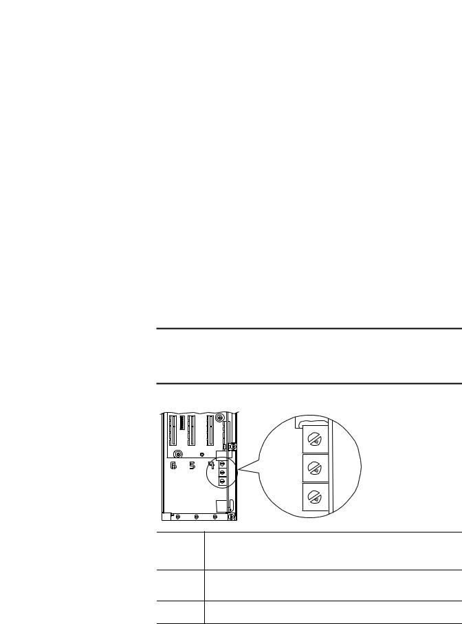
Figure 1 - Setting the IP Address Switches
Hundreds
Position
Tens
Position
Ones
Position
4 |
5 |
|
3
2
1 |
0 |
|
|
4 |
5 |
|
|
3 |
|
2 |
|
1 |
0 |
|
|
4 |
5 |
|
|
3 |
|
2 |
|
1 |
0 |
|
6
7 8
9
6
7 8
9
6
7 8
9
Settings |
Description |
001…254 |
The adapter will use the rotary switch settings for the IP address (192.168.1.xxx, where xxx = rotary |
|
switch settings). The value stored in Parameter 36 - [BOOTP] is automatically ignored. |
888Resets the adapter IP address function to factory defaults. Thereafter, the drive must be powered down, the switches set to a correct value (001…254), and then the drive must be powered up again to accept the new address.
Any other |
Disables the rotary switches and requires using Parameter 36 - [BOOTP] to select the BOOTP server |
setting |
as the source for the IP address or, if disabled, selects the adapter parameters as the source. |
Rockwell Automation Publication 750COM-UM001E-EN-P - October 2013 |
19 |
Chapter 2 Installing the Adapter
Connecting the Adapter to the Network
The switch settings can be verified by viewing Diagnostic Device Item number 68 (page 111) with any of the following drive configuration tools:
•PowerFlex 20-HIM-A6 or 20-HIM-C6S HIM
•Connected Components Workbench software, version 1.02 or later
•DriveExplorer software, version 6.01 or later
•DriveExecutive software, version 5.01 or later
Also, you can use Parameter 37 - [Net Addr Src], a read-only parameter, to verify the selected setting for Parameter 36 - [BOOTP].
ATTENTION: Risk of injury or death exists. The PowerFlex drive may contain high voltages that can cause injury or death. Remove power from the drive, and then verify power has been discharged before connecting the embedded EtherNet/IP adapter to the network.
1.Remove power from the drive.
2.Remove the drive cover and lift up the drive HIM bezel to its open position to access the drive control pod.
3.Use static control precautions.
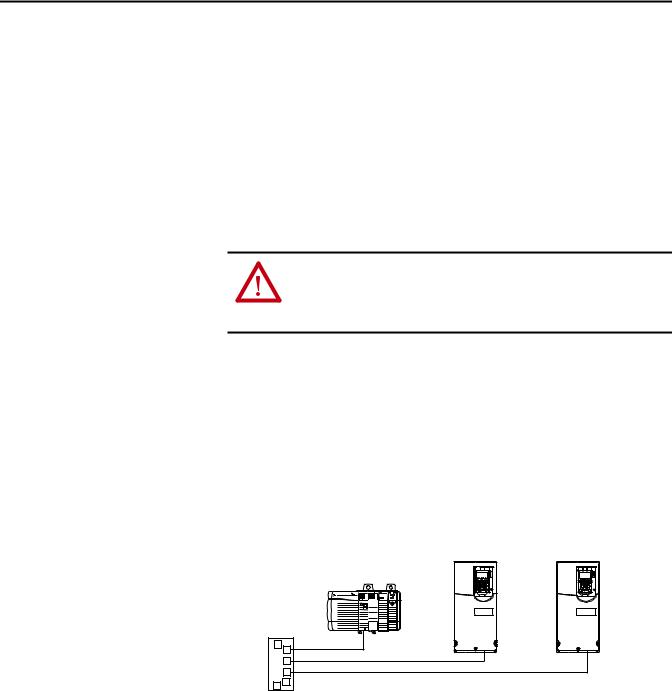
4.Connect one end of an Ethernet cable to the network.
See Figure 2 for an example of wiring to an EtherNet/IP network.
Figure 2 - Connecting the Ethernet Cable to the Network
Controller |
PowerFlex 755 Drives |
|
(each with embedded EtherNet/IP adapter) |
||
(ControlLogix shown with |
||
|
||
1756-ENBT Bridge) |
|
|
Ethernet |
|
|
Switch |
|
5.Route the other end of the Ethernet cable through the bottom of the PowerFlex 755 drive, and insert the cable plug into the embedded EtherNet/IP adapter mating socket (item 3 in Components on page 11).
20 |
Rockwell Automation Publication 750COM-UM001E-EN-P - October 2013 |
Installing the Adapter |
Chapter 2 |
|
|
Applying Power
ATTENTION: Risk of equipment damage, injury, or death exists. Unpredictable operation may occur if you fail to verify that parameter settings are compatible with your application. Verify that settings are compatible with your application before applying power to the drive.
Install the drive cover, and apply power to the drive. The embedded EtherNet/IP adapter receives its power from the drive. When you apply power to the embedded EtherNet/IP adapter for the first time, its ENET status indicator should be steady green or flashing green after an initialization. If it is red, there is a problem. See Chapter 7, Troubleshooting.
Start-Up Status Indications
After power has been applied, the drive STS (status) indicator and the embedded EtherNet/IP adapter ENET and LINK status indicators can be viewed on the front of the drive (Figure 3). Possible start-up status indications are shown in Table 1.
Figure 3 - Drive and Adapter Status Indicators
|
|
|
Rockwell Automation Publication 750COM-UM001E-EN-P - October 2013 |
21 |

Chapter 2 Installing the Adapter
|
|
|
Table 1 - Drive and Adapter Start-Up Status Indications |
|
|
|
|
|
|
Item |
Name |
Color |
State |
Description |
|
|
|
|
|
|
|
|
|
Drive STS Indicator |
|
|
|
|
|
|
STS |
Green |
Flashing |
Drive ready but not running, and no faults are present. |
|
(Status) |
|
|
|
|
|
Steady |
Drive running, no faults are present. |
|
|
|
|
||
|
|
|
|
|
|
|
Yellow |
Flashing |
When running, a type 2 (non-configurable) alarm condition exists – drive continues to run. When stopped, |
|
|
|
|
a start inhibit condition exists and the drive cannot be started (see drive parameter 933 - [Start Inhibit]). |
|
|
|
|
|
|
|
|
Steady |
A type 1 (user configurable) alarm condition exists, but the drive continues to run. |
|
|
|
|
|
|
|
Red |
Flashing |
A major fault has occurred. Drive will stop. Drive cannot be started until fault condition is cleared. |
|
|
|
|
|
|
|
|
Steady |
A non-resettable fault has occurred. |
|
|
|
|
|
|
|
Red/Yellow |
Flashing Alternately |
A minor fault has occurred. Use drive parameter 950 - [Minor Flt Config] to enable. If not enabled, acts like |
|
|
|
|
a major fault. When running, the drive continues to run. System is brought to a stop under system control. |
|
|
|
|
The fault must be cleared to continue. |
|
|
|
|
|
|
|
Yellow/Green |
Flashing Alternately |
When running, a type 1 alarm exists. |
|
|
|
|
|
|
|
Green/Red |
Flashing Alternately |
Drive is firmware updating. |
|
|
|
|
|
|
|
|
Embedded EtherNet/IP Adapter Status Indicators |
|
|
|
|
|
|
|
ENET |
Unlit |
Off |
Adapter and/or network is not powered, adapter is not properly connected to the network, or adapter |
|
|
|
|
needs an IP address. |
|
|
|
|
|
|
|
Red |
Flashing |
An EtherNet/IP connection has timed out. |
|
|
|
|
|
|
|
|
Steady |
Adapter failed the duplicate IP address detection test. |
|
|
|
|
|
|
|
Red/Green |
Flashing Alternately |
Adapter is performing a self-test. |
|
|
|
|
|
|
|
Green |
Flashing |
Adapter is properly connected, but is not communicating with any devices on the network. |
|
|
|
|
|
|
|
|
Steady |
Adapter is properly connected and communicating on the network. |
|
|
|
|
|
|
LINK |
Unlit |
Off |
Adapter is not powered or is not transmitting on the network. |
|
|
|
|
|
|
|
Green |
Flashing |
Adapter is properly connected and transmitting data packets on the network. |
|
|
|
|
|
|
|
|
Steady |
Adapter is properly connected, but is not transmitting on the network. |
|
|
|
|
|
After verifying correct operation, swing down the drive HIM bezel to its closed position and install the drive cover. For more details on status indicator operation, see page 108.
Configuring and Verifying Key Drive Parameters
The PowerFlex 755 drive can be separately configured for the control and Reference functions in various combinations. For example, you could set the drive to have its control come from a peripheral or terminal block with the Reference coming from the network. Or you could set the drive to have its control come from the network with the Reference coming from another peripheral or terminal block. Or you could set the drive to have both its control and Reference come from the network.
The following steps in this section assume that the drive will receive the Logic
Command and Reference from the network.
1.Verify that drive Parameter 301 - [Access Level] is set to ‘1’ (Advanced) or ‘2’ (Expert) to access the required parameters in this procedure.
22 |
Rockwell Automation Publication 750COM-UM001E-EN-P - October 2013 |
Installing the Adapter |
Chapter 2 |
|
|
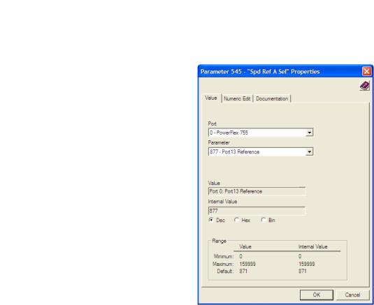
2.Use drive Parameter 545 - [Speed Ref A Sel] to set the drive speed Reference.
a. Set the Port field to ‘0 - PowerFlex 755’ as shown below.
b.Set the Parameter field to point to the port in which the embedded EtherNet/IP adapter is located (always ‘Port 13 Reference’ – the drive port dedicated to the embedded EtherNet/IP adapter).
The number ‘877’ in the Parameter field of the example dialog box above is the parameter in the drive that points to the port.
3.Verify that drive Parameter 930 - [Speed Ref Source] is reporting that the source of the Reference to the drive (Port 0) is the port in which the embedded EtherNet/IP adapter resides (always ‘Port 13 Reference’).
This ensures that any Reference commanded from the network can be monitored by using drive Parameter 002 - [Commanded SpdRef ]. If a problem occurs, this verification step provides the diagnostic capability to determine whether the drive/embedded adapter or the network is the cause.
4.If hard-wired discrete digital inputs are not used to control the drive, verify that all unused digital input drive parameters are set to ‘0’ (Not Used).
Rockwell Automation Publication 750COM-UM001E-EN-P - October 2013 |
23 |

Chapter 2 Installing the Adapter
Commissioning the Adapter |
To commission the embedded EtherNet/IP adapter, you must set a unique IP |
|
address. See the Glossary for details about IP addresses. When using the adapter |
|
switches, see Setting the IP Address on page 18 for details. When not using these |
|
switches, a BOOTP server or adapter parameters can be used to set the IP address |
|
after connecting the adapter to the network and applying power to the drive. |
|
By default, the adapter is configured so that you must set the IP address using a |
|
BOOTP server. For details, see Using a BOOTP Server on page 26. To set the IP |
|
address using adapter parameters, see Using Adapter Parameters on page 30. |
|
|
|
IMPORTANT New settings for some adapter parameters (for example, Parameters 38 - [IP |
|
Addr Cfg 1] through 41 - [IP Addr Cfg 4]) are recognized only when power is |
|
applied to the adapter or it is reset. After you change parameter settings, cycle |
|
power or reset the adapter. |
|
|
24 |
Rockwell Automation Publication 750COM-UM001E-EN-P - October 2013 |

Chapter 3
Configuring the Adapter
Configuration Tools
This chapter provides instructions and information for setting the parameters to configure the embedded EtherNet/IP adapter.
Topic |
Page |
|
|
Configuration Tools |
25 |
|
|
Using the PowerFlex 20-HIM-A6 or 20-HIM-C6S HIM to Access Parameters |
26 |
|
|
Setting the Adapter IP Address |
26 |
|
|
Setting the Data Rate |
31 |
|
|
Selecting Master-Slave or Peer-to-Peer Hierarchy |
32 |
|
|
Setting a Fault Action |
38 |
|
|
Setting Web Access Control |
40 |
|
|
Resetting the Adapter |
41 |
|
|
Restoring Adapter Parameters to Factory Defaults |
41 |
|
|
Viewing the Adapter Status Using Parameters |
42 |
|
|
Updating the Adapter Firmware |
43 |
|
|
For a list of parameters, see Appendix B, Adapter Parameters. For definitions of terms in this chapter, see the Glossary.
The embedded EtherNet/IP adapter stores parameters and other information in its own nonvolatile storage (NVS) memory. You must, therefore, access the adapter to view and edit its parameters. The following tools can be used to access the adapter parameters.
Tool |
See |
|
|
PowerFlex 20-HIM-A6 or 20-HIM-C6S HIM |
page 26 |
|
|
BOOTP server |
page 26 |
|
|
Connected Components Workbench software, |
http://www.ab.com/support/abdrives/webupdate/ |
version 1.02 or later |
software.html, or online help (installed with the software) |
|
|
DriveExplorer software, |
http://www.ab.com/drives/driveexplorer, or online help |
version 6.01 or later |
(installed with the software) |
|
|
DriveExecutive software, |
http://www.ab.com/drives/drivetools, or online help |
version 5.01 or later |
(installed with the software) |
|
|
Rockwell Automation Publication 750COM-UM001E-EN-P - October 2013 |
25 |

Chapter 3 Configuring the Adapter
Using the PowerFlex 20-HIM- A6 or 20-HIM-C6S HIM to Access Parameters
Setting the Adapter IP
Address
If your drive has an enhanced PowerFlex 20-HIM-A6 or 20-HIM-C6S HIM, it can be used to access parameters in the adapter.
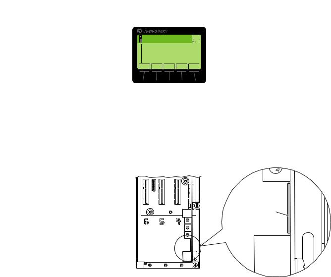
1.Display the Status screen, which is shown on HIM powerup.
2.Use the  or
or  key to scroll to the Port in which the embedded EtherNet/IP adapter resides (always Port 13).
3.Press the PAR# soft key to display the Jump to Param # entry pop-up box.
4.Use the numeric keys to enter the desired parameter number, or use the or soft key to scroll to the desired parameter number.
For details on viewing and editing parameters, see the PowerFlex 20-HIM-A6/- C6S HIM (Human Interface Module) User Manual, publication 20HIMUM001.
When the adapter IP Address switches (Figure 1 on page 19) are set to a value other than 001…254 or 888, Parameter 36 - [BOOTP] determines the source for the adapter node address. By default, the embedded EtherNet/IP adapter is configured to set its IP address, subnet mask, and gateway address by using a BOOTP server. To use a BOOTP server to set the node address, see the procedure in Using a BOOTP Server. To use adapter parameters, see Using Adapter Parameters on page 30.
Using a BOOTP Server
TIP |
If the PowerFlex 755 drive is connected to a Stratix 6000 or Stratix 8000 |
|
managed Ethernet switch and the drive is set for BOOTP mode, the ‘dynamic IP |
|
address assignment by port’ (Stratix 6000) or ‘DHCP persistence’ (Stratix 8000) |
|
feature will set the IP address for the drive. For more details, see the Stratix |
|
6000 Ethernet Managed Switch User Manual, publication 1783-UM001, or the |
|
Stratix 8000 and Stratix 8300 Ethernet Managed Switches User Manual, |
|
publication 1783-UM003. |
There is a variety of BOOTP servers available. The following instructions use Rockwell Automation’s BOOTP/DHCP Server, version 2.3 or later, a free standalone program that incorporates the functionality of standard BOOTP and DHCP utilities with a graphical interface. It is available from http:// www.software.rockwell.com/support/download/detail.cfm?ID=3390. See the Readme file and online Help for directions and more information.
TIP |
If you prefer to configure the IP address, subnet mask, and gateway address |
|
using adapter parameters, set adapter Parameter 36 - [BOOTP] to ‘0’ |
|
(disabled). For details, see Using Adapter Parameters on page 30. |
26 |
Rockwell Automation Publication 750COM-UM001E-EN-P - October 2013 |
Configuring the Adapter |
Chapter 3 |
|
|
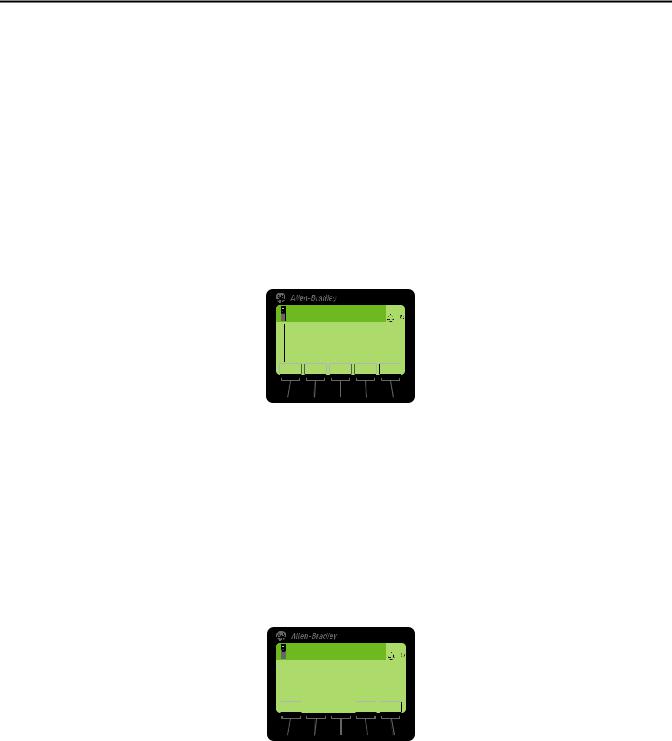
1. Verify that Parameter 36 - [BOOTP] is set to ‘1’ (Enabled).
|
Stopped |
|
|
AUTO |
|
|
0.00 Hz |
|
|
|
F |
Edit BOOTP |
|
|
|
||
|
Enabled |
1 |
|||
|
|
|
|
|
|
0 |
<< |
1 |
|
|
|
ESC ▲ |
▼ |
ENTER |
|||
Value |
Setting |
|
|
0 |
Disabled |
|
|
1 |
Enabled (Default) |
|
|
2.Note the adapter’s hardware Ethernet Address (MAC), which will be used in step 7.
There are two ways to do this:
•Remove the PowerFlex 755 drive cover and locate the adapter’s hardware Ethernet Address (MAC) label on the drive’s Main Control Board (Figure 4).
Figure 4 - Adapter Hardware Address Label Location
2
1
Ethernet Address (MAC) label location
0
8
9
Ethernet
Connector
Drive Control Pod
•Use the HIM to scroll to drive Port 13 and access the embedded EtherNet/IP adapter DIAGNOSTIC folder screen. Then scroll to Diagnostic Items 43…48 (HW Addr 1…6) to view the adapter’s hardware Ethernet Address (MAC). Finally, convert these decimal values to a hex value.
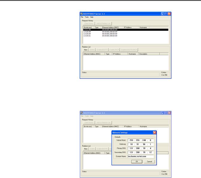
3.On a computer connected to the EtherNet/IP network, start the BOOTP/DHCP software.
The BOOTP/DHCP Server dialog box appears.
Rockwell Automation Publication 750COM-UM001E-EN-P - October 2013 |
27 |
Chapter 3 Configuring the Adapter
To properly configure devices on your EtherNet/IP network, you must configure settings in the BOOTP/DHCP software to match the network.
4.From the Tools menu, choose Network Settings. The Network Settings dialog box opens.
5. Edit the following:
Box |
Type |
|
|
Subnet Mask (1) |
The subnet mask for the embedded EtherNet/IP adapter’s network. |
Gateway (1) |
The IP address of the gateway device on the adapter’s network. |
Primary DNS |
The address of the primary DNS server to be used on the local end of the link for |
|
negotiating with remote devices. |
|
|
Secondary DNS |
Optional—the address of the secondary DNS server to be used on the local end of the |
|
link for negotiating with remote devices when the primary DNS server is unavailable. |
|
|
Domain Name |
The text name corresponding to the numeric IP address that was assigned to the server |
|
that controls the network. |
|
|
(1)For definitions of these terms, see the Glossary.
6.Click OK to apply the settings.
Devices on the network issuing BOOTP/DHCP requests appear in the BOOTP/DHCP Request History list.
28 |
Rockwell Automation Publication 750COM-UM001E-EN-P - October 2013 |
Configuring the Adapter |
Chapter 3 |
|
|
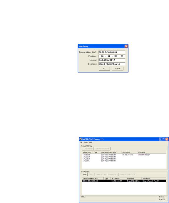
7.In the BOOTP/DHCP Request History list, either double-click the adapter’s Ethernet Address (MAC) noted in step 2, or click New in the Relation List.
The New Entry dialog box appears. In the first instance, the Ethernet Address (MAC) is automatically entered. In the latter instance, it must be manually entered.
8. Edit the following:
Box |
Type |
|
|
IP Address (1) |
A unique IP address for the adapter |
Host Name |
Optional |
|
|
Description |
Optional |
|
|
(1)For definition of this term, see the Glossary.
9.Click OK to apply the settings.
The adapter appears in the Relation List with the new settings.
10.To permanently assign this configuration to the adapter, select the device in the Relation List and click Disable BOOTP/DHCP.
When power is cycled on the adapter, it will use the configuration you assigned it and not issue new BOOTP requests.
TIP |
To enable BOOTP for an embedded adapter that has had BOOTP |
|
disabled, first select the adapter in the Relation List. Then click Enable |
|
BOOTP and, lastly, reset the adapter or power cycle the drive. |
11. From the File menu, choose Save to save the Relation List.
Rockwell Automation Publication 750COM-UM001E-EN-P - October 2013 |
29 |
Chapter 3 Configuring the Adapter
Using Adapter Parameters
By default, the adapter is configured to use a BOOTP server as the source for the adapter IP address, subnet mask, and gateway address. To use adapter parameters instead, you must first disable BOOTP with Parameter 36 - [BOOTP]. Then set the associated adapter parameters as described in the following subsections.
Disable the BOOTP Feature
1.Verify that the IP Address switches (Figure 1 on page 19) are set to any value other than 001…254 or 888.
The default setting is 999.
2.Set the value of Parameter 36 - [BOOTP] to ‘0’ (Disabled).
|
Stopped |
|
|
AUTO |
|
|
0.00 Hz |
|
|
|
F |
Edit BOOTP |
|
|
|
||
|
Disabled |
0 |
|||
|
|
|
|
|
|
0 |
<< 1 |
|
|
|
|
ESC ▲ |
▼ |
ENTER |
|||
Value |
Setting |
|
|
0 |
Disabled |
|
|
1 |
Enabled (Default) |
|
|
3.Reset the adapter by power cycling the drive or by using the HIM’s Reset Device function located in the drive’s DIAGNOSTIC folder.
4.Perform the steps in the following subsections to set the IP address, subnet mask, and gateway address using adapter parameters.
Set the IP Address
1.Verify that Parameter 36 - [BOOTP] is set to ‘0’ (Disabled).
2.Set the value of Parameters 38 - [IP Addr Cfg 1] through 41 - [IP Addr Cfg 4] to a unique IP address.
|
|
|
|
|
|
Default = 0.0.0.0 |
255.255.255.255 |
||||
|
Stopped |
|
|
AUTO |
|
|
|
|
|
|
|
|
0.00 Hz |
|
|
|
F |
[IP Addr Cfg 1] |
|
|
|
||
Edit IP Addr Cfg 1 |
|
|
|
|
|
|
|||||
|
|
0 |
|
|
|
|
[IP Addr Cfg 2] |
|
|
||
|
|
|
|
|
|
|
|
|
|||
|
|
|
|
|
|
|
[IP Addr Cfg |
|
|
||
0 << |
255 |
|
|
|
|
3] |
|
||||
ESC |
|
ENTER |
|
|
|
|
|
|
|||
|
|
[IP Addr Cfg 4] |
|||||||||
|
|
|
|
|
|
|
|
||||
3.Reset the adapter by power cycling the drive or by using the HIM’s Reset Device function located in the drive’s DIAGNOSTIC folder.
The ENET status indicator will be steady green or flashing green if the IP address is correctly configured.
Set the Subnet Mask
1. Verify that Parameter 36 - [BOOTP] is set to ‘0’ (Disabled).
30 |
Rockwell Automation Publication 750COM-UM001E-EN-P - October 2013 |
Loading...