


2094-xxxx
Table of contents
 Loading...
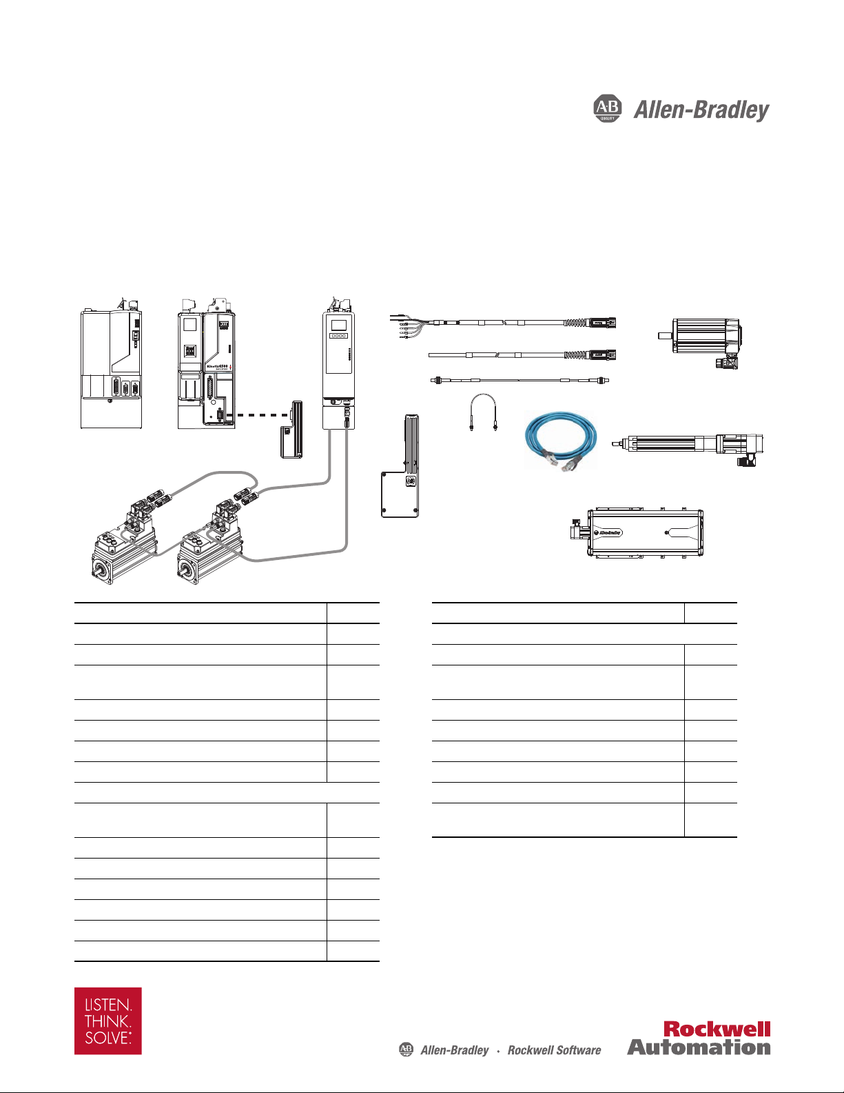
Design Guide
Motor Cables,
Interface Cables,
Connector Kits, and Other
Drive Accessories
Kinetix 6000
Servo Drives
Rotary Motion
Linear Motion
Kinetix 6200 and Kinetix 6500
Servo Drives
Kinetix 6000M
Integrated Drive-Motor
Systems
Kinetix 6000 and Kinetix 6200/6500 Drive Systems
Catalog Numbers 2094-ACxx-Mxx-S, 2094-BCxx-Mxx-S, 2094-AMxx-S, 2094-BMxx-S
2094-BCxx-Mxx-M, 2094-BMxx-M, 2094-SE02F-M00-Sx, 2094-EN02D-M01-Sx, 2094-SEPM-B24-S
Topic Page Topic, continued Page
Introduction 2 Linear Motion System Combinations
Kinetix 6000 and Kinetix 6200/6500 Drive Systems 3 LDAT-Series Integrated Linear Thrusters 65
Kinetix 6000 and Kinetix 6200/6500 System Examples 5
2090-Series Motor/Actuator Cables Overview 7 MP-Series Integrated Linear Stages 87
Kinetix 6000M Integrated Drive-Motor Systems 9 MP-Series Electric Cylinders 94
Kinetix 6000M Integrated Drive-Motor System Example 9 MP-Series Heavy Duty Electric Cylinders 97
Kinetix 6000M Integrated Drive-Motor System Performance 15 LDC-Series Linear Motors 104
Rotary Motion System Combinations LDL-Series Linear Motors 115
Kinetix 6000 Drive Rotary Performance Example with Peak
Enhancement Feature
MP-Series Low Inertia Motors 18
MP-Series Medium Inertia Motors 33
MP-Series Food Grade Motors 45
MP-Series Stainless Steel Motors 52
RDD-Series Direct Drive Motors 55
TL-Series (Bulletin TLY) Motors 61
17 Additional Resources 119
Kinetix 6000 Drive Linear Performance Example with Peak
Enhancement Feature
86
Kinetix 6000 and Kinetix 6200/6500 Drive Systems
IMPORTANT
Introduction
This publication assumes that your application uses the Kinetix® 6000, Kinetix 6200, or Kinetix 6500 drive family and that
you have already determined your motor/actuator series. To revisit those decisions, refer to the Kinetix Motion Control
Selection Guide, publication GMC-SG001
With Kinetix 6000 and Kinetix 6200 drive systems, Kinetix 6000M integrated drive-motor (IDM) systems are another
option. Cables between the IDM units and the IDM power interface module (IPIM) are unique to IDM systems.
Accessories shared with the Bulletin 2094 drive system include sercos fiber-optic cables and safe-off headers and cables.
The purpose of this publication is to assist you in identifying the drive system components and accessory items you’ll need
for your drive and motor/actuator combination or Kinetix 6000M integrated drive-motor system. Diagrams in this
publication illustrate how many of the common drive accessory items are used in a typical system, but refer to the Kinetix
Motion Accessories Technical Data, publication GMC-TD004
Also provided are drive/motor or drive/actuator system combinations that include the following:
• Motor/cable combinations table
• Drive and motor/actuator performance specification table
• Torque/speed curves with each motor matched to the drive with optimum performance
, or Motion Analyzer software.
, for detailed accessory descriptions and specifications.
Performance specification data and curves reflect nominal system performance of a typical system with motor/drive at
rated ambient temperature and line voltage. For additional information on ambients, line conditions, and valid
combinations not shown in this publication, refer to Motion Analyzer software.
These system combinations do not include all possible motor/drive combinations. Please refer to Motion Analyzer software to
verify compatibility. Download from http://www.ab.rockwellautomation.com/motion-control/motion-analyzer-software
.
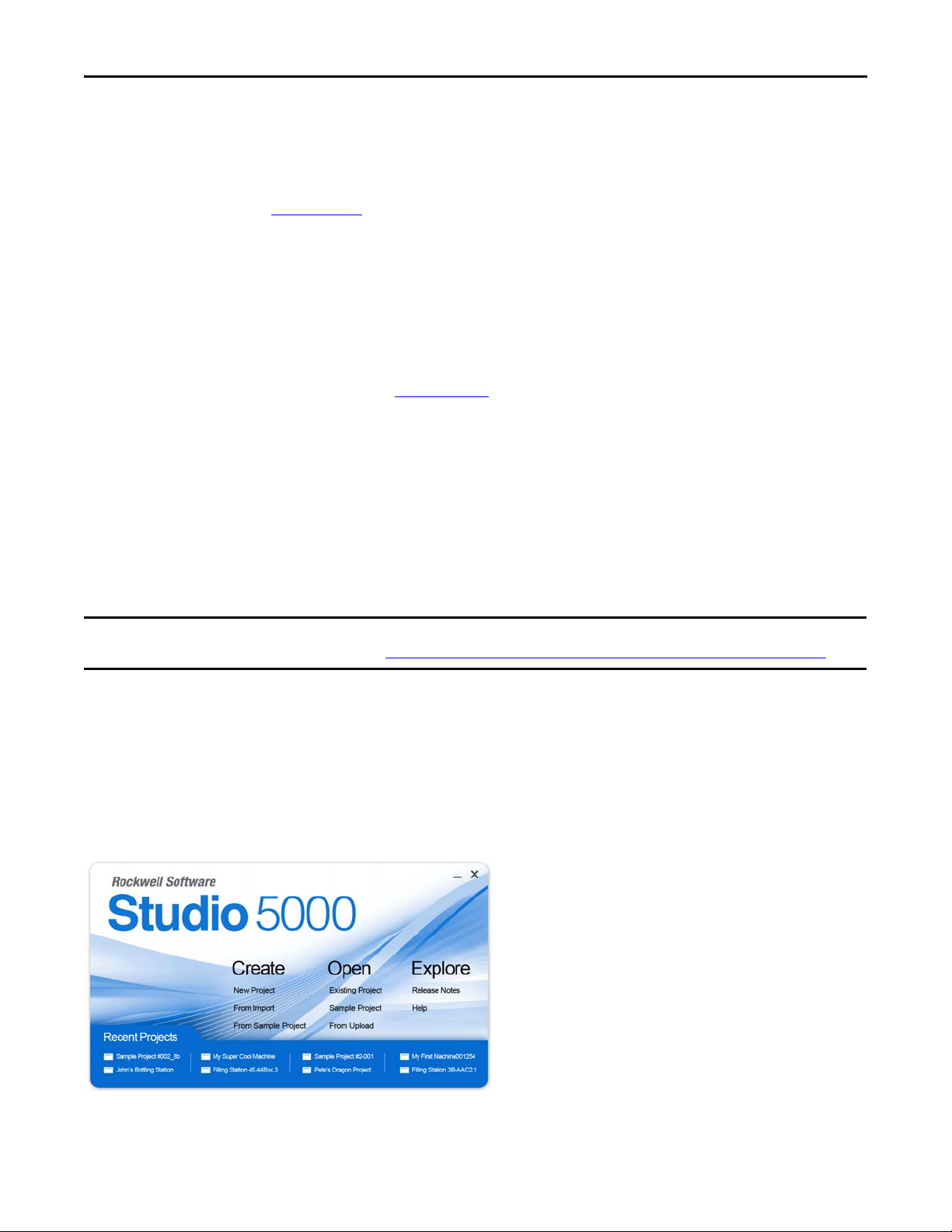
Studio 5000 Environment
The Studio 5000™ Engineering and Design Environment combines engineering and design elements into a common
environment. The first element in the Studio 5000 environment is the Logix Designer application. The Logix Designer
application is the rebranding of RSLogix™ 5000 software and will continue to be the product to program Logix5000™
controllers for discrete, process, batch, motion, safety, and drive-based solutions.
The Studio 5000 environment is the foundation for the future of Rockwell Automation® engineering design tools and
capabilities. It is the one place for design engineers to develop all the elements of their control system.
2 Rockwell Automation Publication GMC-RM003C-EN-P - September 2013

Kinetix 6000 and Kinetix 6200/6500 Drive Systems
Kinetix 6000 and Kinetix 6200/6500 Drive Systems
For each Kinetix 6000, Kinetix 6200, or Kinetix 6500 drive system, you need to know the drive and motor/actuator catalog
numbers to determine the motor power and feedback cable catalog numbers. Interface cables, connector kits, and a Bulletin
2094 power rail are also required. Optional equipment includes the 2094 shunt module, slot-filler modules, line interface
module, AC line filter, and others. Example diagrams of the required equipment listed on this page are shown on page 5
.
For Kinetix 6000M integrated drive-motor system information including cables and torque/speed curves, refer to page 9
For Kinetix 6000 and Kinetix 6200/6500 (rotary motion) system combinations, refer to page 17
combinations, refer to page 86
.
. For linear motion system
.
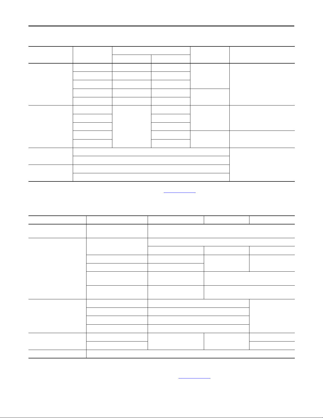
Determine What You Need
These tables list the drive modules and accessory items available for the Kinetix 6000 and Kinetix 6200/6500 drive systems.
Kinetix 6000 Drive Modules
Drive Module Drive Cat. No.
2094-AC05-MP5-S 3 kW, 10 A 1.2 kW, 5 A
2094-AC05-M01-S 3 kW, 10 A 1.9 kW, 9 A
Integrated axis module
(IAM) 200V-class
Integrated axis module
(IAM) 400V-class
Axis module (AM)
200V-class
Axis module (AM)
400V-class
2094-AC09-M02-S 6 kW, 19 A 3.4 kW, 15 A
2094-AC16-M03-S 11.3 kW, 36 A 5.5 kW, 25 A
2094-AC32-M05-S 22.5 kW, 71 A 11.0 kW, 49 A Double wide
2094-BC01-MP5-S 6 kW, 9 A 1.8 kW, 4.0 A
2094-BC02-M02-S 15 kW, 23 A 6.6 kW, 14.6 A
2094-BC04-M03-S 28 kW, 42 A 13.5 kW, 30 A
2094-BC07-M05-S 45 kW, 68 A 22.0 kW, 49 A
2094-AMP5-S
2094-AM01-S 1.9 kW, 9 A
2094-AM02-S 3.4 kW, 15 A
2094-AM03-S 5.5 kW, 25 A
2094-AM05-S 11.0 kW, 49 A
2094-BMP5-S
2094-BM02-S 6.6 kW, 14.6 A
2094-BM03-S 13.5 kW, 30 A
2094-BM05-S 22.0 kW, 49 A
(1)
Continuous Output Ratings
Converter (ADC) Inverter (A, 0-pk)
1.2 kW, 5 A
N/A
1.8 kW, 4.0 A
N/A
Slot Usage Quantity
Single wide
1 for each power rail
Single wide2094-BC01-M01-S 6 kW, 9 A 3.9 kW, 8.6 A
Double wide
Single wide Up to 7 for each 8-axis power rail
Single wide Up to 7 for each 8-axis power rail2094-BM01-S 3.9 kW, 8.6 A
Double wide Up to 3 for each 8-axis power rail
(1) The -S designator indicates safe-off functionality.
Refer to the Kinetix Servo Drives Technical Data, publication GMC-TD003, for detailed descriptions and additional
specifications for the Kinetix 6000 drive family.
Rockwell Automation Publication GMC-RM003C-EN-P - September 2013 3
Kinetix 6000 and Kinetix 6200/6500 Drive Systems
Kinetix 6200 and Kinetix 6500 Drive Modules
Drive Module Drive Cat. No.
2094-BC01-MP5-M 6 kW, 9 A 1.8 kW, 4.0 A
2094-BC01-M01-M 6 kW, 9 A 3.9 kW, 8.6 A
IAM power module
400V-class
AM power module
400V-class
Kinetix 6200 Control
module (sercos)
Kinetix 6500 Control
module (EtherNet/IP)
2094-BC02-M02-M 15 kW, 23 A 6.6 kW, 14.6 A
2094-BC04-M03-M 28 kW, 42 A 13.5 kW, 30 A
2094-BC07-M05-M 45 kW, 68 A 22.0 kW, 49 A
2094-BMP5-M
2094-BM02-M 6.6 kW, 14.6 A
2094-BM03-M 13.5 kW, 30 A
2094-BM05-M 22.0 kW, 49 A
2094-SE02F-M00-S0, Safe torque-off
2094-SE02F-M00-S1, Safe speed monitoring
2094-EN02D-M01-S0, Safe Torque-off
2094-EN02D-M01-S1, Safe speed monitoring
Continuous Output Ratings
Converter (A
N/A
)Inverter (A, 0-pk)
DC
Slot Usage Quantity
Single wide
1 for each power rail
Double wide
1.8 kW, 4.0 A
Single wide Up to 7 for each 8-axis power rail2094-BM01-M 3.9 kW, 8.6 A
Double wide Up to 3 for each 8-axis power rail
1 for each IAM and AM power module
Refer to the Kinetix Servo Drives Technical Data, publication GMC-TD003, for detailed descriptions and additional
specifications for the Kinetix 6200 and Kinetix 6500 drive families.
Required Drive Accessories
Drive Accessory Description Kinetix 6000 Systems Kinetix 6200 Systems Kinetix 6500 Systems
2094 power rail
Low-profile connector kits
(required for flying-lead cables)
Sercos fiber-optic cables
(required as needed)
Ethernet network cables
Motor power and feedback cables Refer to the specific drive/motor combination for the motor cables required for your system.
Backplane and mounting fixture for
Bulletin 2094 drive modules
Motor feedback connections
Auxiliary feedback connections 2090-K6CK-D15F
I/O connections 2090-K6CK-D26M
I/O, safety, and auxiliary feedback
connections
I/O and cascading safe torque-off
connections
Plastic, in-cabinet duty 2090-SCEPx-x
Plastic, on-machine duty 2090-SCNPx-x
Plastic, outdoor and conduit duty 2090-SCVPx-x
Glass, outdoor and conduit duty 2090-SCVGx-x
Double-ended, non-flex, shielded
Double-ended, high-flex, shielded 1585J-M8UBJM-x
2094-PRSx, available for 1, 2, 3, 4, 5, 7, and 8-axis drive systems
2090-K6CK-D15M
2090-K6CK-KENDAT
N/A 2090-K6CK-D44M
N/A 2090-K6CK-D44S0
N/A N/A
(1)
N/A N/A
N/A N/A
N/A
1585J-M8CBJM-x
(1) Applies to only Bulletin RDB direct-drive motors with EnDat encoder.
Refer to the Kinetix Motion Accessories Technical Data, publication GMC-TD004, for detailed descriptions and
specifications of these required servo drive accessories.
4 Rockwell Automation Publication GMC-RM003C-EN-P - September 2013
Kinetix 6000 and Kinetix 6200/6500 Drive Systems
Kinetix 6200 or Kinetix 6500 Control Module
(2094-SE02F-M00-Sx module is shown)
Kinetix 6200 or Kinetix 6500
IAM or AM Power Module
(2094-BC02-M02-M IAM module is shown)
Kinetix 6000 IAM or AM Drive Module
(2094-BC02-M02-S IAM module is shown)
0.2 m
(7.1 in.)
62006200
SAFE SPEED
62006200
SAFE SPEED
62006200
SAFE SPEED
0.2 m
(7.1 in.)
0.1 m
(5.1 in.)
2090-SCxxx-x Sercos Fiber-optic
Drive-to-Drive Cables
2094-BMxx-S
AM Modules
2094-BMxx-M AM Power Modules with
2094-SE02F-M00-Sx Control Modules
2094-BCxx-Mxx-M
IAM Power Module
with
2094-SE02F-M00-Sx
Kinetix 6200 Control Module
2094-PRSx
Power Rail
2094-PRSx
Power Ra il
2094-K6CK-xxxx
Low-profile Connector Kits for
I/O, Safety, and Auxiliary Feedback
Bulletin 2090 Motor Feedback Cables
Bulletin 2090 Motor Power Cables
2094-BMxx-M Axis Modules (5) with
2094-EN02D-M01-Sx Control Modules (5)
2094-BCxx-Mxx-M
IAM Power Module
with
2094-EN02D-M01-Sx
Kinetix 6500 Control Module
1585J-M8CBJM-OM3
0.3 m (1.0 ft) Ethernet cable
for drive-to-drive connections.
2094-PRSx
Power Rail
2094-PRSx
Power Rail
2094-K6CK-xxxx
Low-profile Connector Kits for
I/O, Safety, and Feedback Connections
Bulletin 2090 Motor Feedback Cables
Bulletin 2090 Motor Power Cables
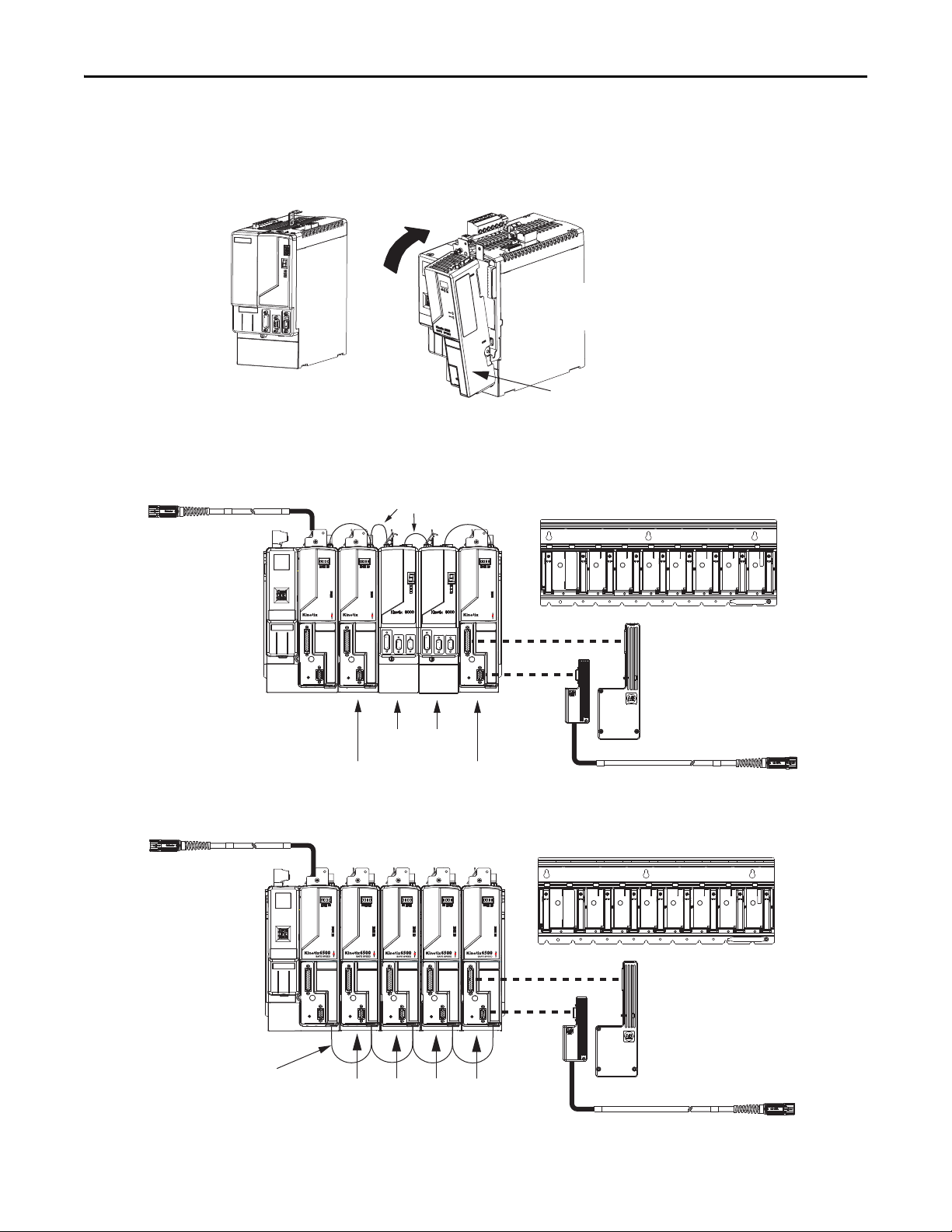
Kinetix 6000 and Kinetix 6200/6500 System Examples
These system examples illustrate how the required drive modules and accessories are used in a typical system.
Drive Module Examples
Kinetix 6000 and Kinetix 6200 Drive System Example (sercos interface)
Kinetix 6500 Drive System Example (EtherNet/IP network)
Rockwell Automation Publication GMC-RM003C-EN-P - September 2013 5
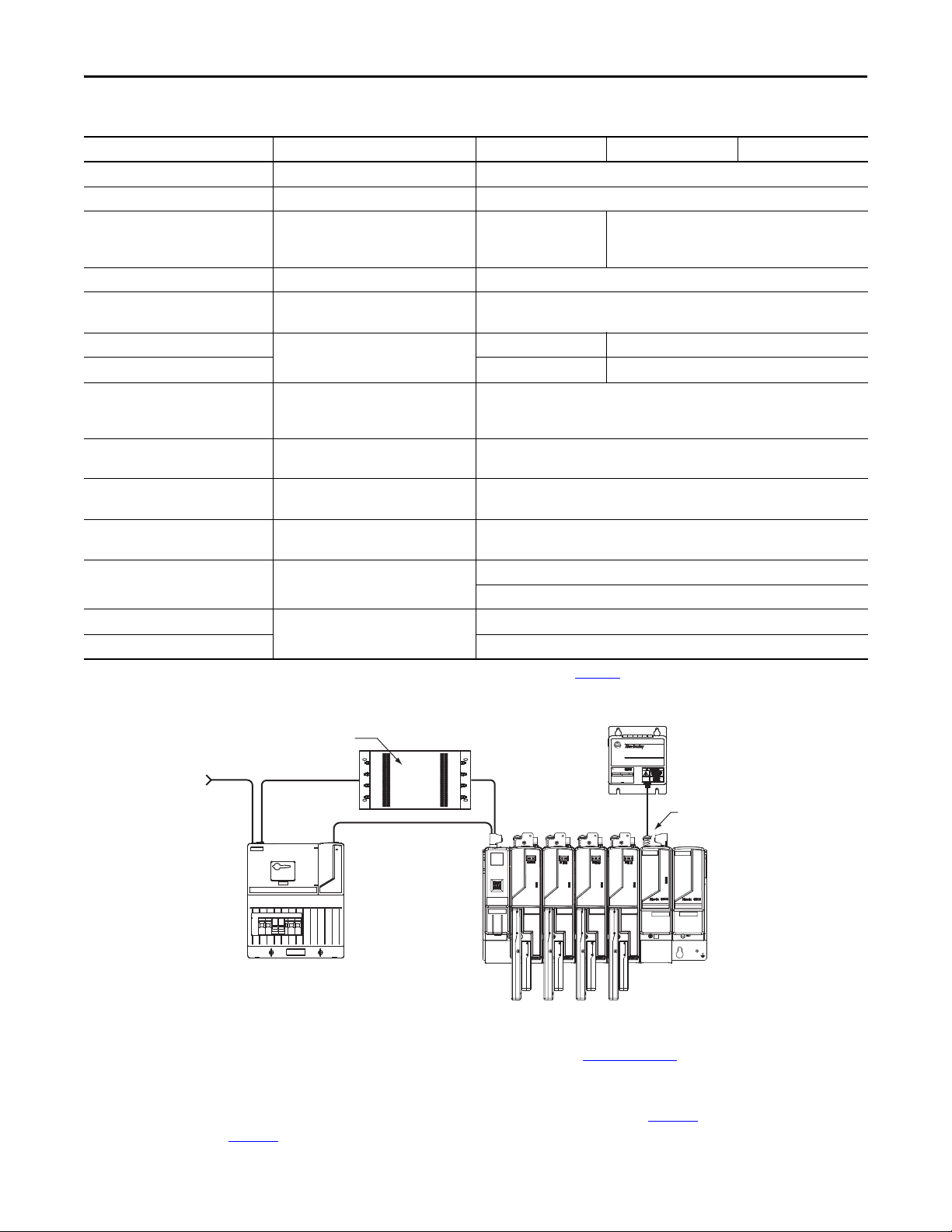
Kinetix 6000 and Kinetix 6200/6500 Drive Systems
BULLETIN 1394 300W SHUNT MODULE
ALLEN-BRADLEY
FOR USE WITH 1394-SJT22-X SYSTEM MODULE
CAT. PART SER.
INPUT DC INPUT AC
FOR FUSE REPLACEMENT USE:
BUSSMAN CAT. NO.
R
Shunt Module
MAIN VAC
Three-p hase
Input Power
115/230V Control Power
2090-XXLF-xxxx
AC Lin e Filter
(required for CE)
2094-xLxxS
Line Interface Module
(optional component)
2094-BSP2
Shunt Module
(optional component)
1394-SRxxxx
External Passive Shunt Module
(optional component)
2094-PRF
Slot Filler Module
(required to fill any
unused slots)
Optional Drive Accessories
Drive Accessory Description Kinetix 6000 Systems Kinetix 6200 Systems Kinetix 6500 Systems
2094 shunt module 200 W continuous shunt power 2094-BSP2
2094 slot-filler module Fills unused slots on the 2094 power rail 2094-PRF
2094 line interface module
Replaces many of the common input power
devices for your drive system
2090 AC line filters AC line conditioning for EMC 2090-XXLF-xxxx
1394 external passive shunt modules
Safety headers
Safety interface cables
(1)
(1)
Shunt capacity in addition to the 2094-BSP2
shunt module
Cascading safe-off connections from driveto-drive
Panel space-saving brackets that let you
2094 mounting brackets
mount the line filter behind the LIM module
or power rail
External auxiliary encoders
Connector sets
Resistive brake module (RBM)
Allen-Bradley® sine/cosine and incremental
external encoders
Replacement connectors for input power,
control power, motor power, and others
Physically and electrically separate the drive
power output from its corresponding motor
RBM interface cables Motor power, RBM to drive
8720MC regenerative power supply (RPS)
8720MC line reactors 8720MC-LRxx-xxxx
Power components required in regenerative
applications
2094-ALxxS, 2094-AL09,
2094-BLxxS, 2094-BL02,
2094-BLxxS, 2094-BL02, 2094-XL75S-Cx
2094-XL75S-Cx
1394-SRxxx
2090-XNSM-x N/A
1202-Cxx 2090-CS0DSDS-AAxx
2094-XNBRKT-1
Bulletin 842A, 844D, 845H, and 845T
2094-xxxCON, 2094-xxxINV, and 2094-XNSHT
2090-XBxxx-xx
2090-XXNRB-10F0P5
2090-XXNRB-8F0P6
8720MC-RPSxxx
(1) For drive system examples of safe-off headers and cables, refer to the Kinetix Motion Accessories Technical Data, publication GMC-TD004.
Kinetix 6000 and Kinetix 6200/6500 Power Accessories Example
Motor-end cable connector kits, for use when building your own cables, and panel-mounted breakout components are also
available. Refer to the Kinetix Motion Accessories Technical Data, publication GMC-TD004
specifications of optional servo drive accessories.
For Kinetix 6000 and Kinetix 6200/6500 (rotary motion) system combinations, refer to page 17
combinations, refer to page 86
.
, for detailed descriptions and
. For linear motion system
6 Rockwell Automation Publication GMC-RM003C-EN-P - September 2013
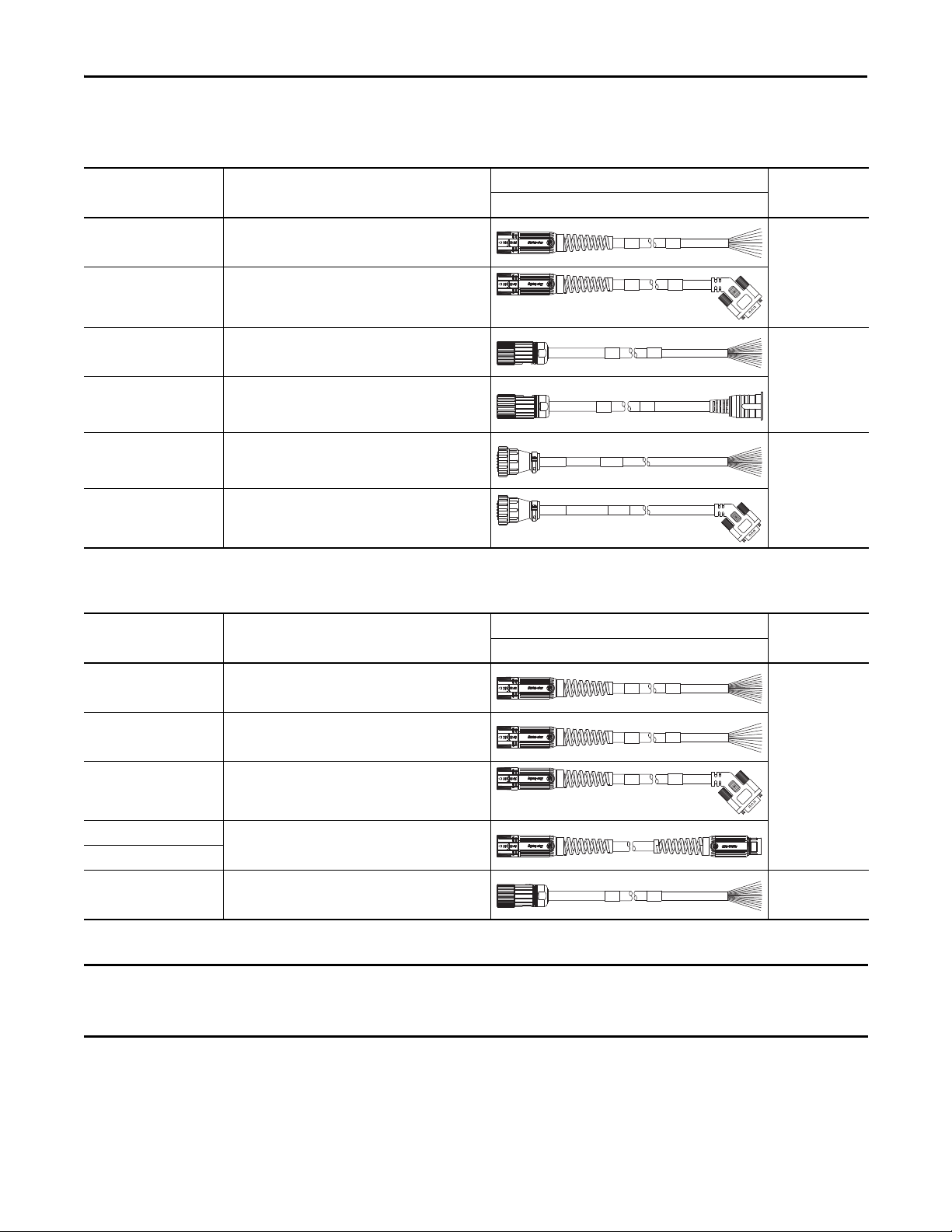
2090-Series Motor/Actuator Cables Overview
IMPORTANT
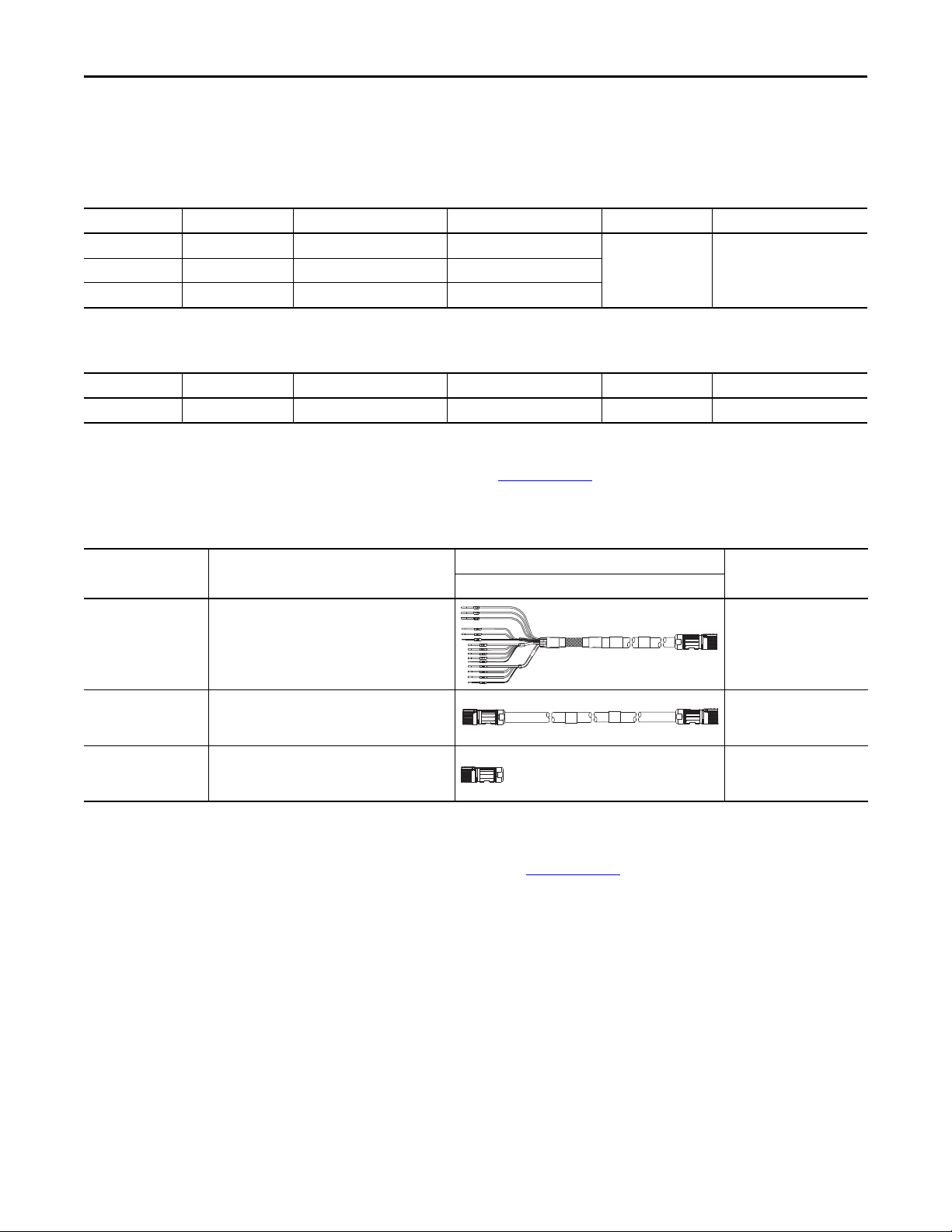
Feedback Cable Descriptions (standard, non-flex)
Kinetix 6000 and Kinetix 6200/6500 Drive Systems
Standard Cable
Cat. No.
2090-CFBM7DF-CEAAxx
2090-CFBM7DD-CEAAxx
2090-XXNFMF-Sxx
2090-CFBM4E2-CATR
2090-CFBM6DF-CBAAxx
2090-CFBM6DD-CCAAxx
(1) Threaded DIN connector (motor end) and bayonet connector for 2090-XXNFMP-Sxx cable.
Description
• Drive-end flying-leads (DF)
• High-resolution or resolver applications (CE)
• Drive-end 15-pin connector (DD)
• High-resolution or resolver applications (CE)
• Drive-end flying-leads
• High-resolution or incremental applications
• Drive-end bayonet (E2), transition (TR) cable
• Motor-end threaded DIN (M4)
• All feedback types (CA)
• Drive-end flying-leads (DF)
• High-resolution, battery backup or
Incremental applications (CB)
• Drive-end 15-pin connector (DD)
• Incremental applications only (CC)
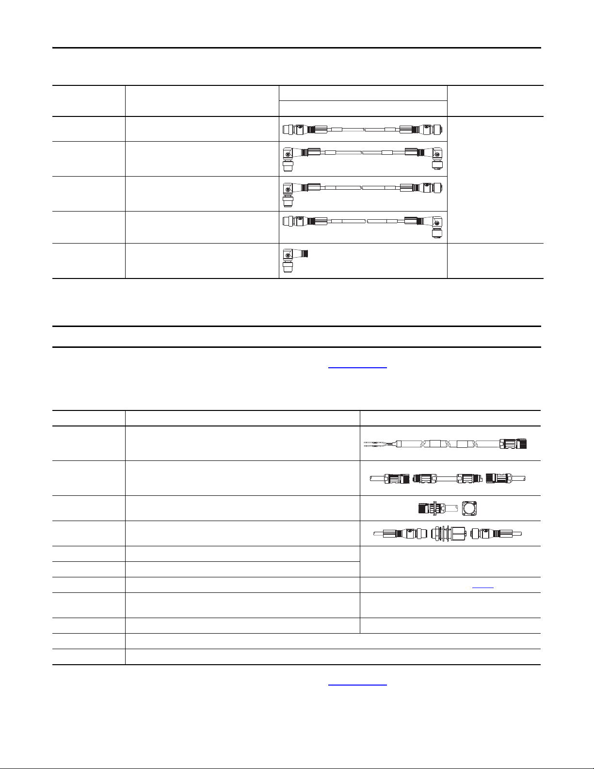
Feedback Cable Descriptions (continuous-flex)
Continuous-flex Cable
Cat. No.
Description
Cable Configuration
Motor/Actuator End Drive End
(1)
Cable Configuration
Motor/Actuator End Drive End
Motor/Actuator
Connector
SpeedTec DIN
(M7)
Threaded DIN
(M4)
Circular Plastic
(M6)
Motor/Actuator
Connector
2090-CFBM7DF-CDAFxx
2090-CFBM7DF-CEAFxx
2090-CFBM7DD-CEAFxx
2090-CFBM7E7-CDAFxx
2090-CFBM7E7-CEAFxx
2090-CFBM4DF-CDAFxx
(1) SpeedTec DIN connector (motor end) and male connector for extending SpeedTec or threaded DIN cable.
• Drive-end flying-leads (DF)
• High-resolution or incremental applications (CD)
• Drive-end flying-leads (DF)
• High-resolution or resolver applications (CE)
• Drive-end 15-pin connector (DD)
• High-resolution or resolver applications (CE)
• Drive-end (male) connector, extension (E7)
• Motor-end SpeedTec DIN cable plug (M7)
• Drive-end flying-leads
• High-resolution or incremental applications
(1)
Feedback cables with the CE designation, for example 2090-CFBM7DF-CEAAxx, are intended for high-resolution encoder or
resolver applications and have fewer conductors than feedback cables with the CD designation, for example
2090-CFBM7DF-CDAFxx, which are intended for high-resolution or incremental encoder applications.
SpeedTec DIN
(M7)
Threaded DIN
(M4)
Rockwell Automation Publication GMC-RM003C-EN-P - September 2013 7
Kinetix 6000 and Kinetix 6200/6500 Drive Systems
BR+
BR-
BR+
BR-
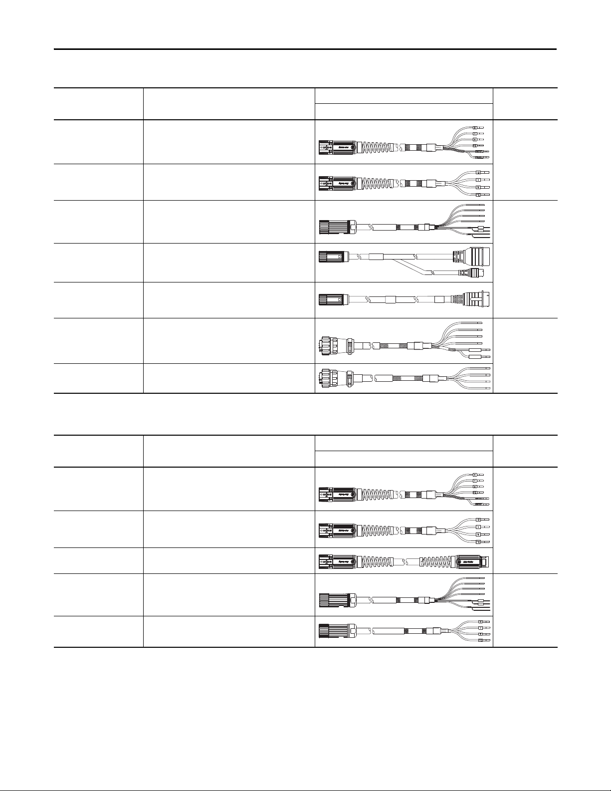
Power/Brake Cable Descriptions (standard, non-flex)
Standard Cable
Cat. No.
2090-CPBM7DF-xxAAxx
2090-CPWM7DF-xxAAxx
2090-XXNPMF-xxSxx
2090-CPBM4E2-xxTR
2090-CPWM4E2-xxTR
2090-CPBM6DF-16AAxx
2090-CPWM6DF-16AAxx
Description
• Drive-end flying-leads (DF)
• Power /brake wires (PB)
• Drive-end flying-leads (DF)
• Power wire s only (P W)
• Drive-end flying-leads
• Power /brake wires
• Drive-end bayonet (E2), transition (TR) cable
• Motor-end threaded DIN (M4)
• Power /brake wires (PB)
• Drive-end bayonet (E2), transition (TR) cable
• Motor-end threaded DIN (M4)
• Power wire s only (P W)
• Drive-end flying-leads (DF)
• Power /brake wires (PB)
• Drive-end flying-leads (DF)
• Power wire s only (P W)
Cable Configuration
Motor/Actuator End Drive End
Motor/Actuator
Connector
SpeedTec DIN
(M7)
(1)
Threaded DIN
(M4)
(1)
MBRK+
Circular Plastic
MBRK-
(M6)
(1) Threaded DIN connector (motor end) and bayonet connector for 2090-XXNFMP-Sxx cable.
Power/Brake Cable Descriptions (continuous-flex)
Continuous-flex Cable
Cat. No.
2090-CPBM7DF-xxAFxx
2090-CPWM7DF-xxAFxx
2090-CPBM7E7-xxAFxx
2090-CPBM4DF-xxAFxx
2090-CPWM4DF-xxAFxx
(1) SpeedTec DIN connector (motor end) and male connector for extending SpeedTec or threaded DIN cable.
Description
• Drive-end flying-leads (DF)
• Power /brake wires (PB)
• Drive-end flying-leads (DF)
• Power wire s only (P W)
• Drive-end (male) connector, extension (E7)
• Motor-end SpeedTec DIN cable plug (M7)
• Drive-end flying-leads (DF)
• Power /brake wires (PB)
• Drive-end flying-leads (DF)
• Power wire s only (P W)
(1)
Cable Configuration
Motor/Actuator End Drive End
Motor/Actuator
Connector
SpeedTec DIN
(M7)
Threaded DIN
(M4)
8 Rockwell Automation Publication GMC-RM003C-EN-P - September 2013
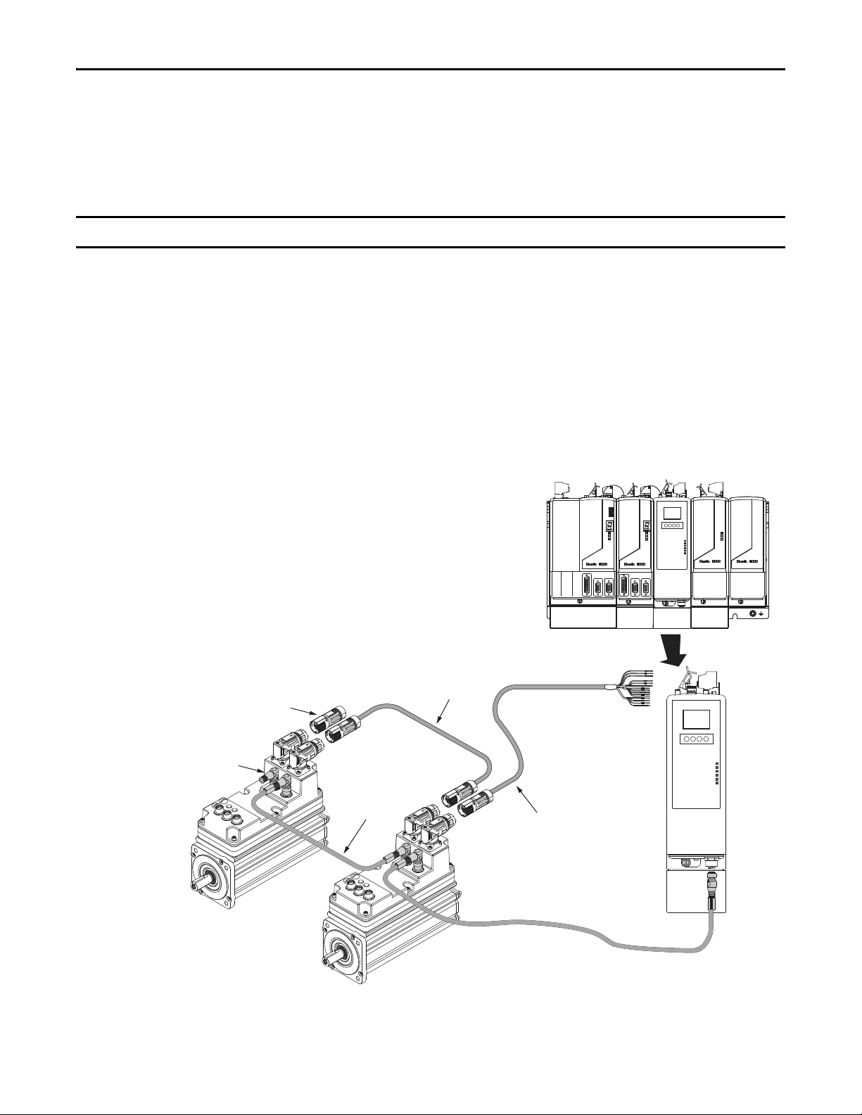
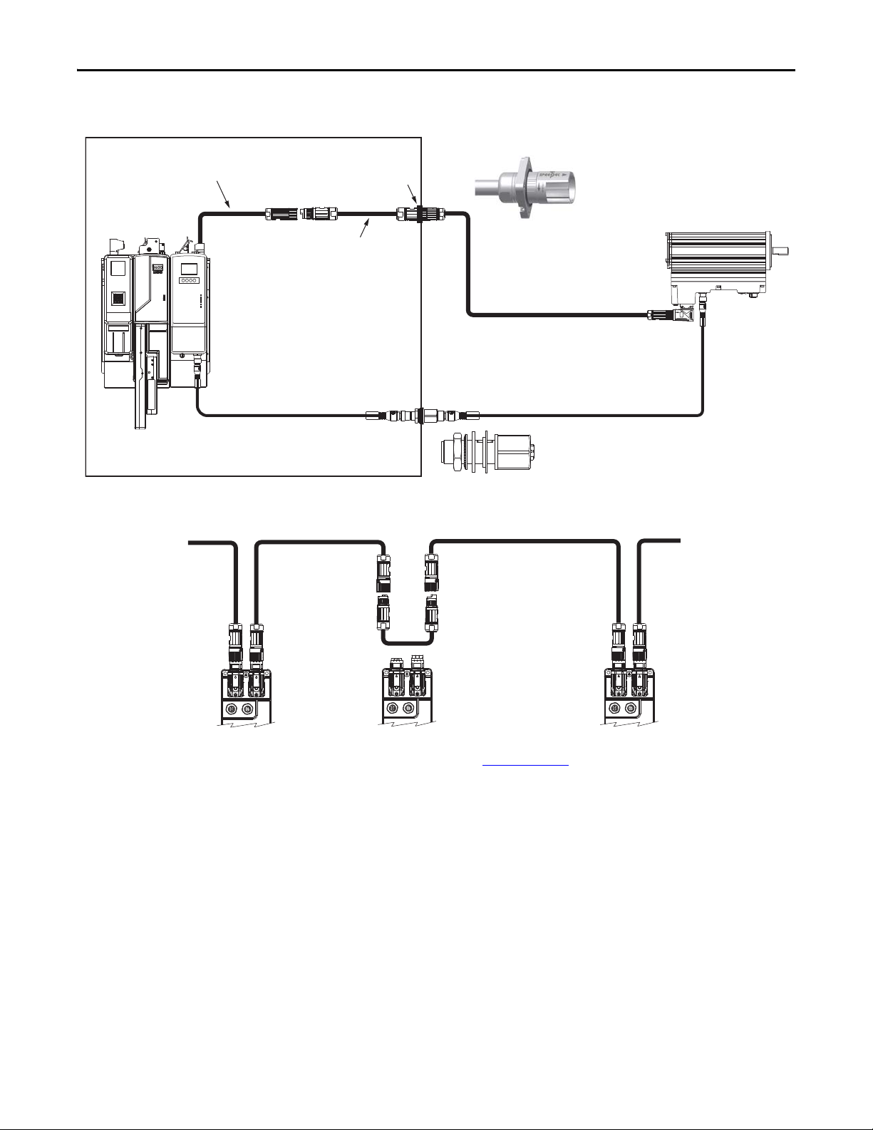
Kinetix 6000 and Kinetix 6200/6500 Drive Systems
IMPORTANT
2090-CHBP8S8-12AAxx Hybrid Cable
(IDM unit-to-unit)
MDF-SBxxxxx-Qx8xB-S
IDM Units
2090-CNSxPxS-AAxx
Network Cables
2090-CNSSPxS-AAxx
Network Cable
2090-CHBIFS8-12AAxx Hybrid Cable
(IPIM module to first IDM unit)
2090-CTSRP Network Terminator
(last IDM unit only)
2090-CTHP8 Hybrid Terminator
(last IDM unit only)
2094-SEPM-B24-S
IPIM Module
Kinetix 6000 or Kinetix 6200
(400V-class) Servo Drive System
(Kinetix 6000 system is shown)
Kinetix 6000M Integrated Drive-Motor Systems
For each Kinetix 6000M integrated drive-motor system, you need to know the integrated drive-motor (IDM) unit and
IDM power interface module (IPIM) catalog numbers. The IPIM module is compatible with the Bulletin 2094 power rail
in any configuration with Kinetix 6000 or Kinetix 6200 (400V-class) drive systems.
Kinetix 6000 drives must be series B or series C.
You also need hybrid cables, network cables, and terminators. Optional equipment includes digital input cables, the hybrid
coupler cable, bulkhead adapter kits, the holding brake manual release cable, and Bulletin 2090 safe-off headers and
1202-Cxx safety cables.
Kinetix 6000M Integrated Drive-Motor System Example
This configuration illustrates the components needed to add Kinetix 6000M IDM units to a 400V-class Kinetix 6000 or
Kinetix 6200 multi-axis servo drive system. The IDM power interface module (IPIM) is mounted to the Bulletin 2094
power rail and connects to the sercos fiber-optic ring. The IDM units are wired to the IPIM module.
Typical Kinetix 6000M Integrated Drive-Motor System
Rockwell Automation Publication GMC-RM003C-EN-P - September 2013 9
Kinetix 6000 and Kinetix 6200/6500 Drive Systems
Determine What You Need
These tables list the system components and accessory items available for the Kinetix 6000M IDM drive systems.
Kinetix 6000M Integrated Drive-Motor (IDM) Units
Cat. No. Speed Continuous Torque Peak Torque Features Quantity
MDF-SB1003P 5000 rpm 3.0 N•m (26.5 lb•in) 10.5 N•m (92.9 lb•in)
MDF-SB1153H 3500 rpm 4.8 N•m (42.5 lb•in) 18.5 N•m (164 lb•in)
MDF-SB1304F 3000 rpm 7.25 N•m (64.2 lb•in) 21.75 N•m (192 lb•in)
(1) Use Motion Analyzer software, version 6.00 or later, to determine the maximum number of IDM units to daisy-chain on each IPIM module.
Kinetix 6000M IDM Power Interface Module (IPIM)
Cat. No. Output Bus Voltage Continuous Output Peak Output Slot Usage Quantity
2094-SEPM-B24-S 650V DC 15 kW, 24 A, rms 60 A 1 Up to 4 on each power rail
(1) Use Motion Analyzer software, version 6.00 or later, to determine the maximum number of IPIM modules on a single power rail.
Refer to the Kinetix Rotary Motion Technical Data, publication GMC-TD001, for detailed descriptions and additional
specifications for the Kinetix 6000M integrated drive-motor (IDM) units and IPIM module.
• USDA compliant
food-grade paint
• 400V-class
• Safe-off
Up to 16 on each IPIM module
(1)
(1)
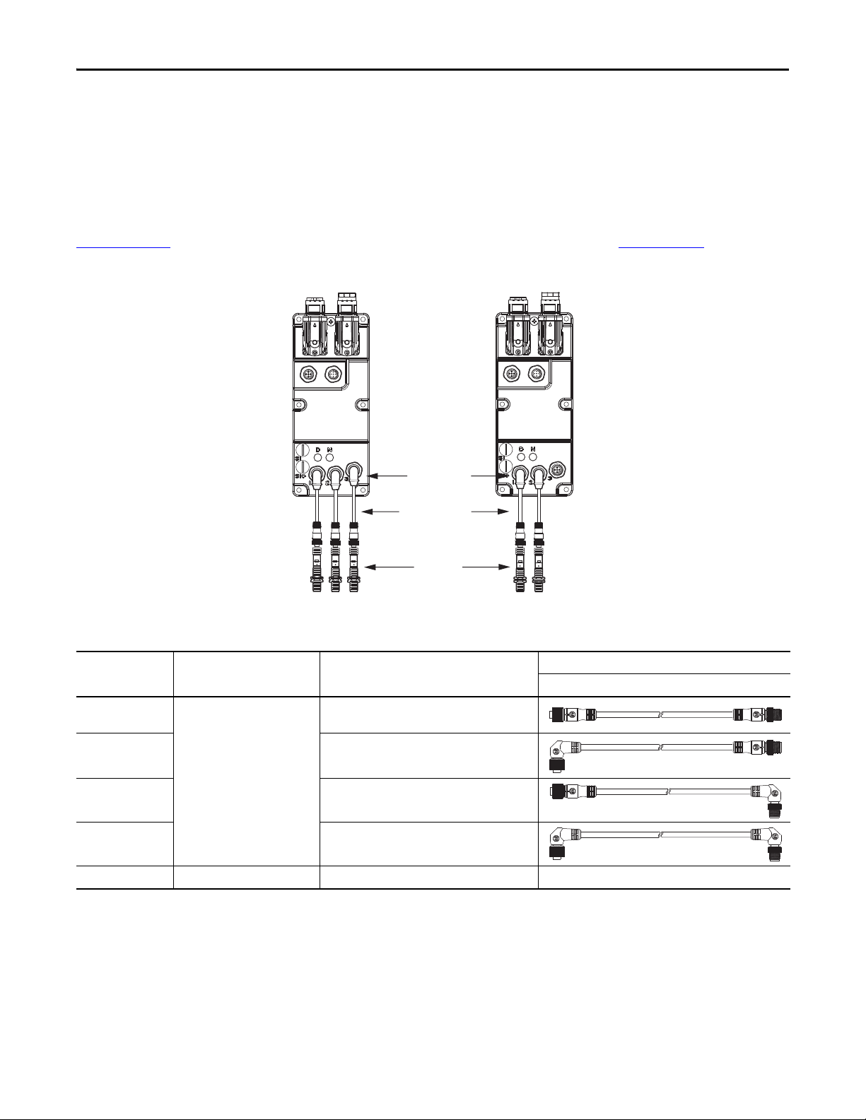
Required Hybrid Cables
Cat. No. Description
From IPIM module (flying-leads) to the first IDM unit
(1)
2090-CHBIFS8-12AAxx
2090-CHBP8S8-12AAxx
2090-CTHP8
(1) Cables are available in standard lengths of 1, 2, 3, 4, 5, 7, 9, 12, 15, 20, and 25 m (3.2, 6.6, 9.8, 13.1, 16.4, 22.9, 29.5, 39.3, 49.2, 65.5, and 82.0 ft).
(2) Cables are available in standard lengths of 0.5, 1, 2, 3, 4, 5, 7, 9, 12, 15, 20, and 25 m (1.6, 3.2, 6.6, 9.8, 13.1, 16.4, 22.9, 29.5, 39.3, 49.2, 65.5, and 82.0 ft).
• IPIM-end flying-leads (IF)
• SpeedTec connector, socket (S8)
IDM unit-to-unit connections
(2)
• SpeedTec connector, pin (P8)
• SpeedTec connector, socket (S8)
Hybrid (SpeedTec) terminator
• Required on last IDM unit, pin (P8)
• Included with each IPIM module
Flying-lead/Pin Socket
Cable Configuration
Quantity
1 required per system (IPIM
module to first IDM unit)
1 required for the second IDM
unit and each additional
downstream IDM unit
1 required per system
Refer to the Kinetix Motion Accessories Technical Data, publication GMC-TD004, for detailed descriptions and
specifications of these required accessories.
10 Rockwell Automation Publication GMC-RM003C-EN-P - September 2013
Required Network Cables
IMPORTANT
Kinetix 6000 and Kinetix 6200/6500 Drive Systems
Cat. No. Description
Cable Configuration
Quantity
Pin Socket
• Straight connector, pin (SP)
2090-CNSSPSS-AAxx
2090-CNSRPRS-AAxx
2090-CNSRPSS-AAxx
2090-CNSSPRS-AAxx
(1)
• Straight connector, socket (SS)
• Right-angle connector, pin (RP)
(1)
• Right-angle connector, socket (RS)
• Not compatible for connection to the IPIM module
• Right-angle connector, pin (RP)
(1)
• Straight connector, socket (SS)
• Not compatible for connection to the IPIM module
• Straight connector, pin (SP)
(1)
• Right-angle connector, socket (RS)
1 required per system (IPIM
module to first IDM unit)
Plus, 1 required for the second
IDM unit and each additional
downstream IDM unit
Network terminator
2090-CTSRP
• Required on last IDM unit, right-angle, pin (RP)
1 required per system
• Included with each IPIM module
(1) Cables are available in standard lengths of 0.5, 1, 2, 3, 4, 5, 7, 9, 12, 15, 20, and 25 m (1.6, 3.2, 6.6, 9.8, 13.1, 16.4, 22.9, 29.5, 39.3, 49.2, 65.5, and 82.0 ft).
(2) This cable must be either 2090-CNSSPSS-AAxx or 2090-CNSSPRS-AA xx. Only straight, pin (SP) connectors fit properly at the IPIM module.
(3) Use of straight or right-angle connectors depends on application.
Right-angle (pin) connectors are not compatible for connection to the IPIM module. Only straight (pin) connectors fit properly.
Refer to the Kinetix Motion Accessories Technical Data, publication GMC-TD004, for detailed descriptions and
specifications of these required accessories.
(2)
(3)
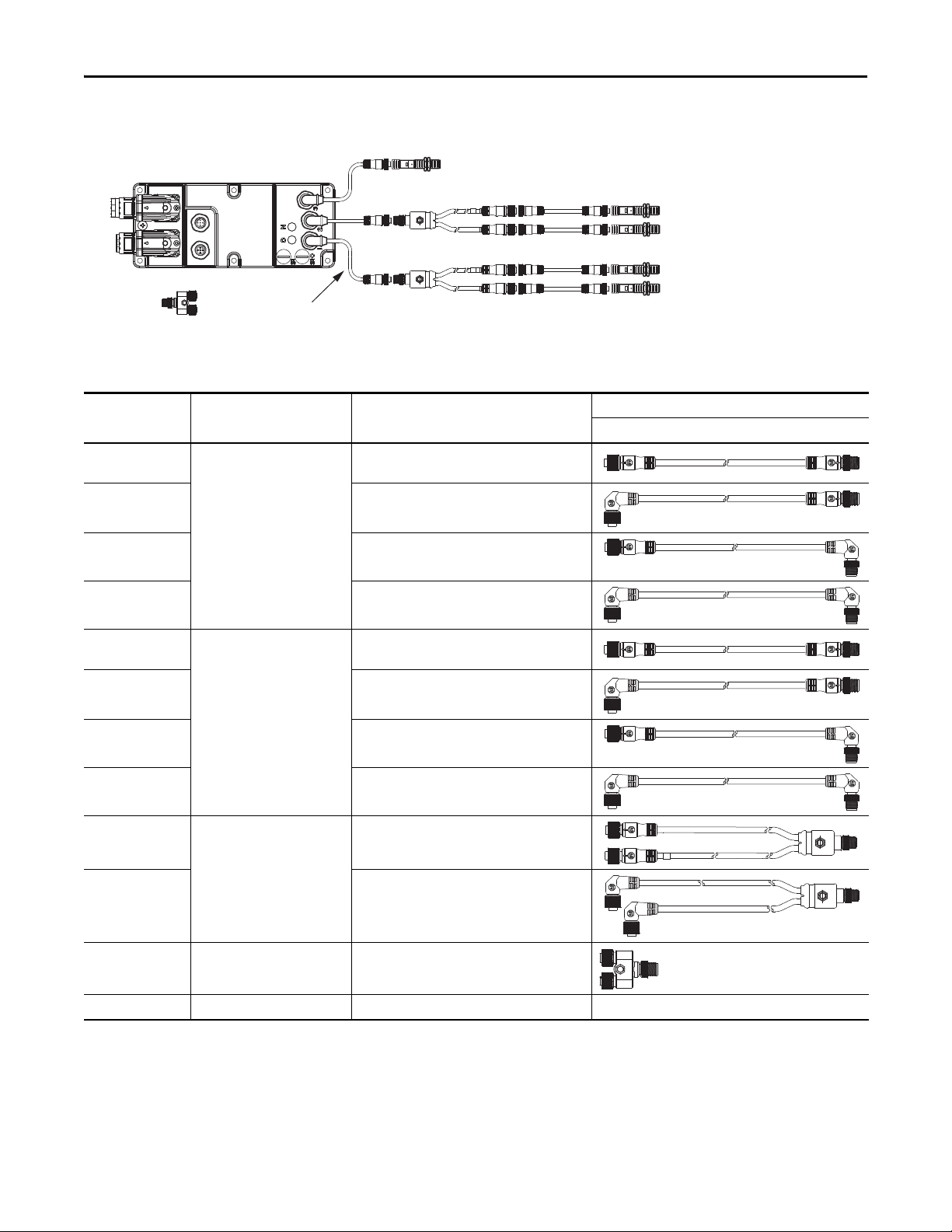
Optional Accessories
Cat. No. Accessory Item Description
Manual brake release cable
2090-CBKS8-16AA03
2090-CCPP8S8
2090-KPB47-12CF
2090-CBUSPSS
2090-XNSM-x Safe-off headers
1202-Cxx Safety cables
Bulletin 889D and 879D DC micro-style patchcords, V-cables, and splitters for digital input connections Refer to Digital Input Cable Examples on page 12
2094-XNIPIM-1 Connector set
2094-SEPM-FUSE Replacement fuses for the IPIM module, 6 each Bussmann part number FWP-50A14Fa
MDF-SB-NODECVR Replacement covers for the node address switches on the IDM units
1485A-M12 Replacement covers for the digital input connectors on the IDM units
• Brake release wires (BK)
• SpeedTec connector, socket (S8)
Hybrid coupler cable connects between two hybrid cables to bypass an IDM unit
• SpeedTec connector, pin (P8)
• SpeedTec connector, socket (S8)
• The hybrid bulkhead adapter secures cables as they pass through the cabinet
• Mating cable attaches on the other side
• The network cable bulkhead adapter feeds signals through the cabinet wall
• Network cables attach on either side
Cascading safe-off connections from drive-to- drive (applies to
Kinetix 6000 drive systems)
Includes hybrid power (DC bus), hybrid communication, safe-off,
and enable input replacement connectors for the IPIM module
Refer to the Kinetix Motion Accessories Technical Data, publication GMC-TD004, for detailed descriptions and
specifications of these optional accessories.
Rockwell Automation Publication GMC-RM003C-EN-P - September 2013 11
Kinetix 6000 and Kinetix 6200/6500 Drive Systems
889D-x4ACDx-x
Patch cords
Input Assignments:
1 = Overtravel- (NC)
2 = Overtravel+ (NC)
3 = Home (NO)
Digital Inputs
(1, 2, 3)
Input Assignments:
1 = Registration 2 (NO)
2 = Registration 1 (NO)
MDF-SBxxxxx
IDM Units
Sensors
1 2 3
1 2
Digital Input Cable Examples
Kinetix 6000M IDM units have three 5-pin, M12, digital input connectors. Allen-Bradley (Bulletin 889D and 879D)
DC micro-style patchcords, splitters, and V-cables are available with straight and right-angle connectors for making
connections from the IDM unit to input sensors.
For the most popular patchcord specifications, refer to the Connection Systems Quick Selection Guide, publication
CNSYS-BR001
Digital Inputs Used for Home and Overtravel Functions
. For complete information, refer to On-Machine™ Connectivity, publication M117-CA001.
Digital Input Accessories Items
Cat. No. Item Type Description
889D-F4ACDM-x
889D-R4ACDM-x
Digital input patchcords
889D-F4ACDE-x
889D-R4ACDE-x
871TS-N12BP18-D4 Sensor (example) Proximity N/A
(1) Patchcords are available in standard lengths of 2, 5, and 10 m (6.6, 16.4, and 32.8 ft).
12 Rockwell Automation Publication GMC-RM003C-EN-P - September 2013
(IDM unit to NC and NO sensors)
(1)
• Straight connector, socket (F)
• Straight connector, pin (M)
• Right-angle connector, socket (R)
• Straight connector, pin (M)
• Straight connector, socket (F)
• Right-angle connector, pin (E)
• Right-angle connector, socket (R)
• Right-angle connector, pin (E)
Socket Pin (IDM unit)
Cable Configuration
Digital Inputs Used for Home, Overtravel, and Registration Functions
879D-F4DM
Splitter
Digital Inputs
(1, 2, 3)
Input Assignments:
2A = Registration 1 (NO)
2B = Overtravel+ (NC)
1A = Overtravel- (NC)
1B = Registration 2 (NO)
MDF-SBxxxxx IDM Unit
889D-x4ACDx-x
Patch cords
Sensors
889D-x4ACDx-x (NO) or
889D-x4ACDx-Vx (NC)
Patch cords
879D-x4ACDM-x
V-ca ble
Input Assignment:
3 = Home (NO)
Digital Input Accessories Items
Kinetix 6000 and Kinetix 6200/6500 Drive Systems
Cat. No. Item Type Description
889D-F4ACDM-x
889D-R4ACDM-x
Digital input patchcords
(1)
• Straight connector, socket (F)
• Straight connector, pin (M)
• Right-angle connector, socket (R)
• Straight connector, pin (M)
• IDM unit to NC and NO sensors
889D-F4ACDE-x
889D-R4ACDE-x
889D-F4ACDM-Vx
889D-R4ACDM-Vx
889D-F4ACDE-Vx
889D-R4ACDE-Vx
879D-F4ACDM-x
879D-R4ACDM-x
• IDM unit to V-cable
• V-ca ble to NO se nsors
Digital input patchcords
(V-cable to NC sensor)
(2)
V-ca bles
(1)
• Straight connector, socket (F)
• Right-angle connector, pin (E)
• Right-angle connector, socket (R)
• Right-angle connector, pin (E)
• Straight connector, socket (F)
• Straight connector, pin (M)
• Right-angle connector, socket (R)
• Straight connector, pin (M)
• Straight connector, socket (F)
• Right-angle connector, pin (E)
• Right-angle connector, socket (R)
• Right-angle connector, pin (E)
• Straight connectors, socket (F)
• Straight connector, pin (M)
• Right-angle connectors, socket (R)
• Straight connector, pin (M)
Cable Configuration
Socket Pin (IDM unit)
879D-F4DM Splitter
(3)
• Straight connectors, socket (F)
• Straight connector, pin (M)
871TS-N12BP18-D4 Sensor (example) Proximity N/A
(1) Patchcords are available in standard lengths of 2, 5, and 10 m (6.6, 16.4, and 32.8 ft).
(2) V-cables are available in standard lengths of 0.3, 1, 2, and 5 m (1.0, 3.2, 6.6, and 16.4 ft).
(3) Splitter can be used in place of the V-cable.
Rockwell Automation Publication GMC-RM003C-EN-P - September 2013 13
Kinetix 6000 and Kinetix 6200/6500 Drive Systems
2090-CHBIFS8-12AAxx
Hybrid Cable
2090-CNSSPSS-AAxx
Network Cable
2090-KPB47-12CF
Hybrid Cable Bulkhead Adapter
2090-CNSSPSS-AAxx
Network Cable
2090-CBUSPSS
Network Cable Bulkhead Adapter
2094 Servo Drive System
(Kinetix 6200 drive system is shown)
2094-SEPM-B24-S
IPIM Module
Enclosure
2090-CHBP8S8-12AAxx
Hybrid Cable
MDF-SBxxxxx IDM Unit
Mounted on the Machine
2090-CCPP8S8
Hybrid Coupler Cable
2090-CCPP8S8 Hybrid Coupler Cable
(IDM unit bypass)
IDM Unit 3
IDM Unit 2
(removed for servicing)
IDM Unit 1
2090-CHBP8S8-12AAxx
Hybrid Cable
2090-CHBP8S8-12AAxx
Hybrid Cable
Bulkhead Adapter Examples
Hybrid Coupler Cable Example
Refer to the Kinetix Motion Accessories Technical Data, publication GMC-TD004, for detailed descriptions and
specifications of these optional accessories.
14 Rockwell Automation Publication GMC-RM003C-EN-P - September 2013
Kinetix 6000 and Kinetix 6200/6500 Drive Systems
IMPORTANT
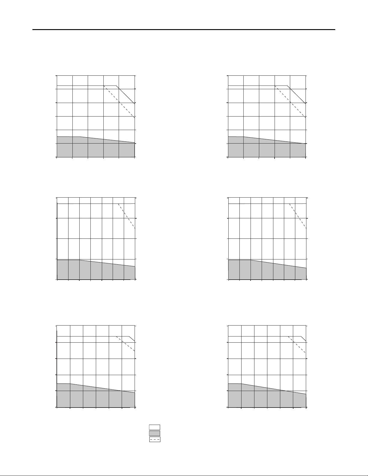
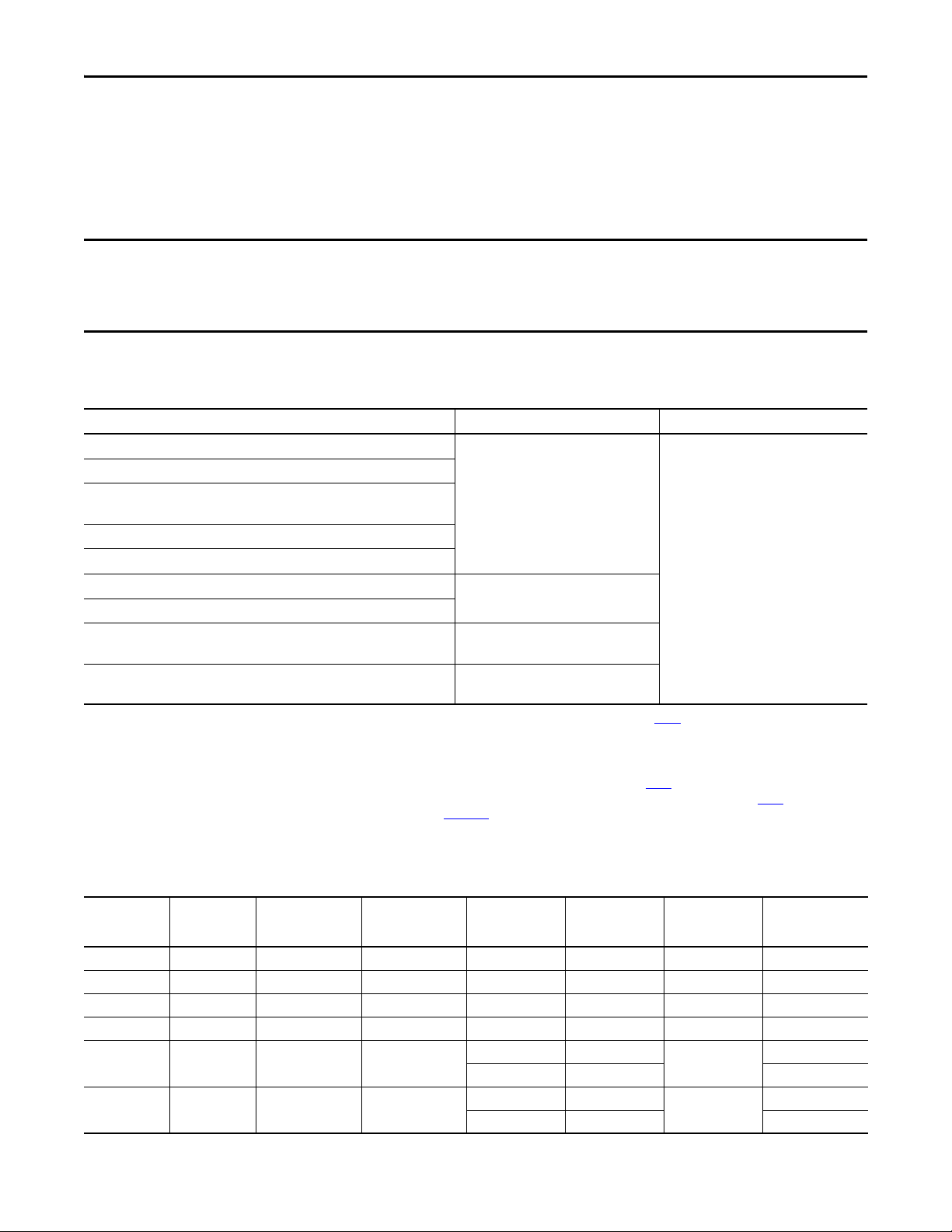
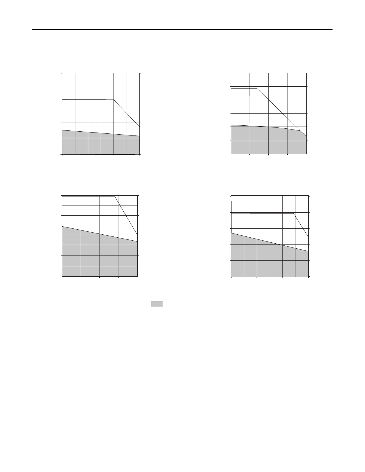
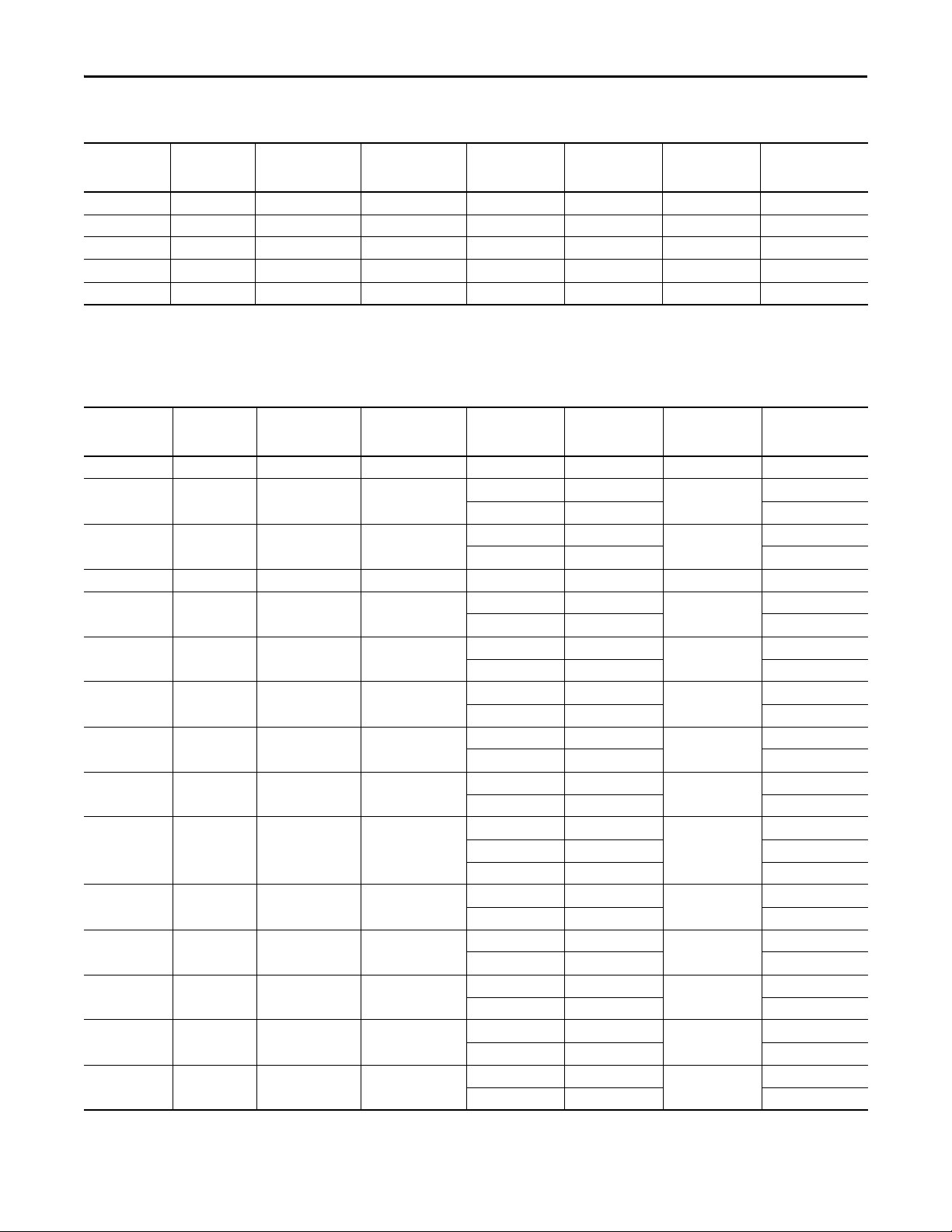
Kinetix 6000M Integrated Drive-Motor System Performance
This section provides system performance information for the Bulletin MDF integrated drive-motor units. Included are
hybrid power and network cable catalog numbers, system performance specifications, and the optimum torque/speed
curves.
The Kinetix 6000M integrated drive-motor systems are compatible with Kinetix 6000 and Kinetix 6200 (400V-class) power rail
configurations. Kinetix 6000 drives must be series B or series C.
Kinetix 6000M (Bulletin MDF) Integrated Drive-Motor Cable Combinations
Motor Cat. No. (400V-class) Hybrid Cables
MDF-SB1003P
2090-CHBIFS8-12AAxx and
2090-CHBP8S8-12AAxx
MDF-SB1304F
(1) Hybrid terminator (catalog number 2090-CTHP8) is included with the IPIM module.
(2) Network terminator (catalog number 2090-CTSRP) is included with the IPIM module.
For cable configuration illustrations and feature descriptions, by catalog number, refer to the Kinetix 6000M Integrated Drive-Motor System Example on page 9.
Cable len gth xx is in meters. Refer to the Kinetix Motion Accessories Technical Data, publication GMC-TD004
(1)
, for standard cable lengths.
Network Cables
2090-CNSxPxS-AAxxMDF-SB1153H
(2)
Performance Specifications with Kinetix 6000M (non-brake) Motors
IDM Drive-Motor
Unit
MDF-SB1003P-xxx2x-S 5000 4.03 3.00 (26.5) 19.0 10.50 (92.9) 1.10
MDF-SB1304F-xxx2x-S 3000 5.80 7.25 (64.2) 20.0 21.75 (192) 1.39
Performance specification data and curves reflect nominal system performance of a typical system at 40 °C (104 °F) ambient and rated line voltage. For additional information on ambient and line conditions,
refer to M otion Analy zer software.
Speed, max
rpm
System Continuous
Stall Current
A 0-pk
System Continuous
Stall Torque
N•m (lb•in)
System Peak
Stall Current
A 0-pk
System Peak
Stall Torque
N•m (lb•in)
Motor Rated
Output
kW
Kinetix 6000M
IPIM Module
2094-SEPM-B24-SMDF-SB1153H-xxx2x-S 3500 4.50 4.80 (42.5) 20.0 18.50 (164) 1.15
Performance Specifications with Kinetix 6000M (brake) Motors
IDM Drive-Motor
Unit
MDF-SB1003P-xxx4x-S 5000 4.03 3.00 (26.5) 19.0 10.50 (92.9) 1.02
MDF-SB1304F-xxx4x-S 3000 5.80 7.25 (64.2) 20.0 21.75 (192) 1.24
Performance specification data and curves reflect nominal system performance of a typical system at 40 °C (104 °F) ambient and rated line voltage. For additional information on ambient and line conditions,
refer to M otion Analy zer software.
Speed, max
rpm
System Continuous
Stall Current
A 0-pk
Rockwell Automation Publication GMC-RM003C-EN-P - September 2013 15
System Continuous
Stall Torque
N•m (lb•in)
System Peak
Stall Current
A 0-pk
System Peak
Stall Torque
N•m (lb•in)
Motor Rated
Output
kW
Kinetix 6000M
IPIM Module
2094-SEPM-B24-SMDF-SB1153H-xxx4x-S 3500 4.50 4.80 (42.5) 20.0 18.50 (164) 1.00
Kinetix 6000 and Kinetix 6200/6500 Drive Systems
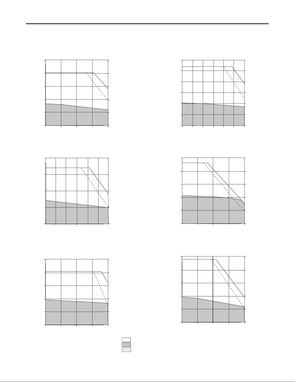
Torque
(N•m)
Torque
(lb•in)
Speed (rpm)
0
2000
4000
30001000
5000
12.0
10.0
8.0
6.0
4.0
2.0
0
106
88.5
70.8
53.1
35.4
17.7
0
2094 Power Rail with 2094-SEPM-B24-S
and MDF-SB1003P
Torque
(N•m)
Torque
(lb•in)
Speed (rpm)
0
2000
4000
30001000
5000
12.0
10.0
8.0
6.0
4.0
2.0
0
106
88.5
70.8
53.1
35.4
17.7
0
2094 Power Rail with 2094-SEPM-B24-S
and MDF-SB1003P (brake)
Torque
(N•m)
Torque
(lb•in)
2094 Power Rail with 2094-SEPM-B24-S
and MDF-SB1153H
0
0
5
10
15
44
88
133
20
177
Speed (rpm)
0
2500
3500
30001000
2000
500
1500
Torque
(N•m)
Torque
(lb•in)
2094 Power Rail with 2094-SEPM-B24-S
and MDF-SB1153H (brake)
0
0
5
10
15
44
88
133
20
177
Speed (rpm)
0
2500
3500
30001000
2000
500
1500
Torque
(N•m)
Torque
(lb•in)
0
0
5
10
15
25
20
44.2
88.5
133
177
221
2094 Power Rail with 2094-SEPM-B24-S
and MDF-SB1304F
Speed (rpm)
0
1000
2000
1500500
3000
2500
Torque
(N•m)
Torque
(lb•in)
0
0
5
10
15
25
20
44.2
88.5
133
177
221
2094 Power Rail with 2094-SEPM-B24-S
and MDF-SB1304F (brake)
Speed (rpm)
0
1000
2000
1500500
3000
2500
= Intermittent operating region
= Continuous operating region
= Drive operation with 400V AC rms input voltage
Kinetix 6000M Integrated Drive-Motor (400V-class) System Performance Curves
16 Rockwell Automation Publication GMC-RM003C-EN-P - September 2013
Kinetix 6000 and Kinetix 6200/6500 Drive Systems
IMPORTANT
IMPORTANT
Torque
(N•m)
Torque
(lb•in)
Speed (rpm)
0
2000
4000
30001000
5000
12.0
10.0
8.0
6.0
4.0
2.0
0
106
88.5
70.8
53.1
35.4
17.7
0
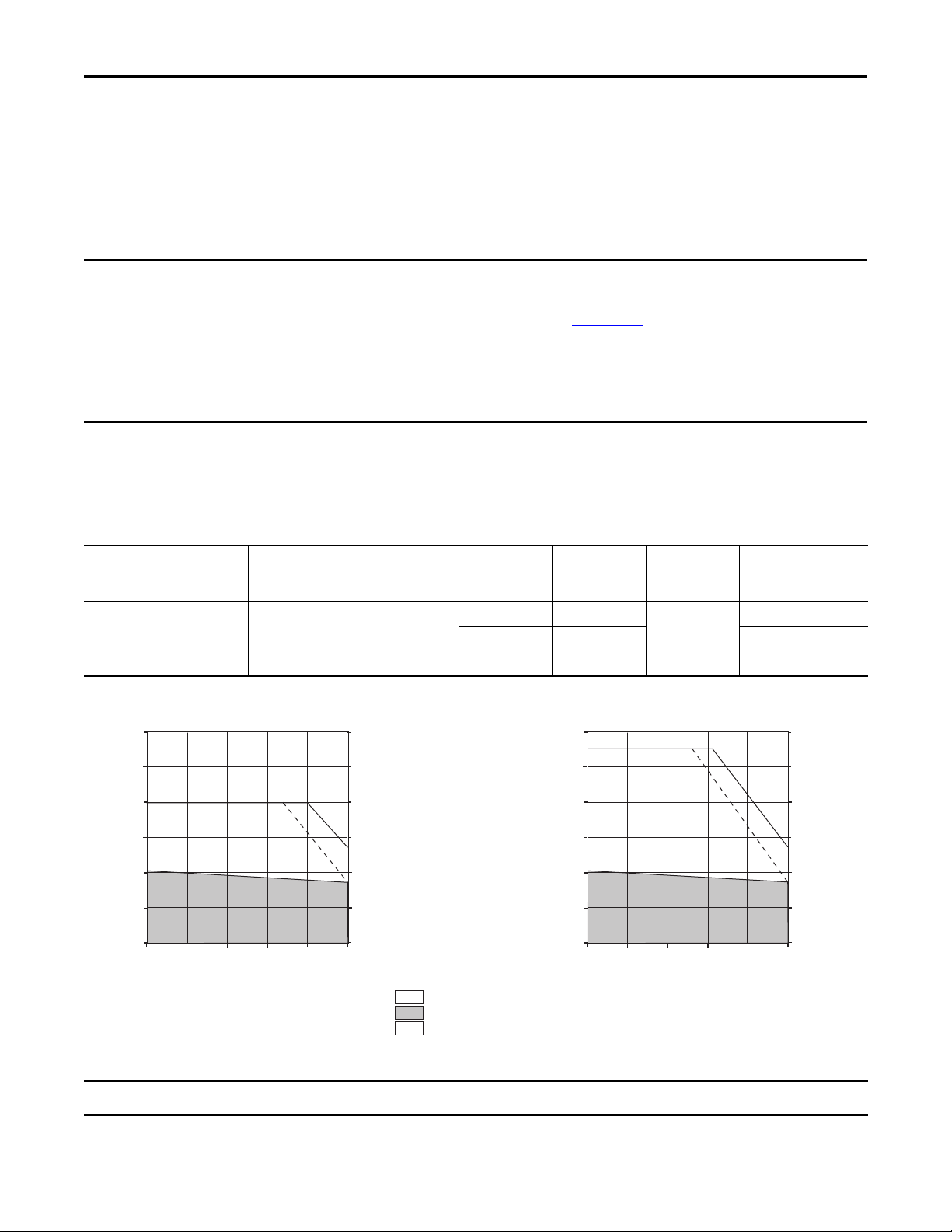
2094-BM01-S @ 150% and MPL-B330P
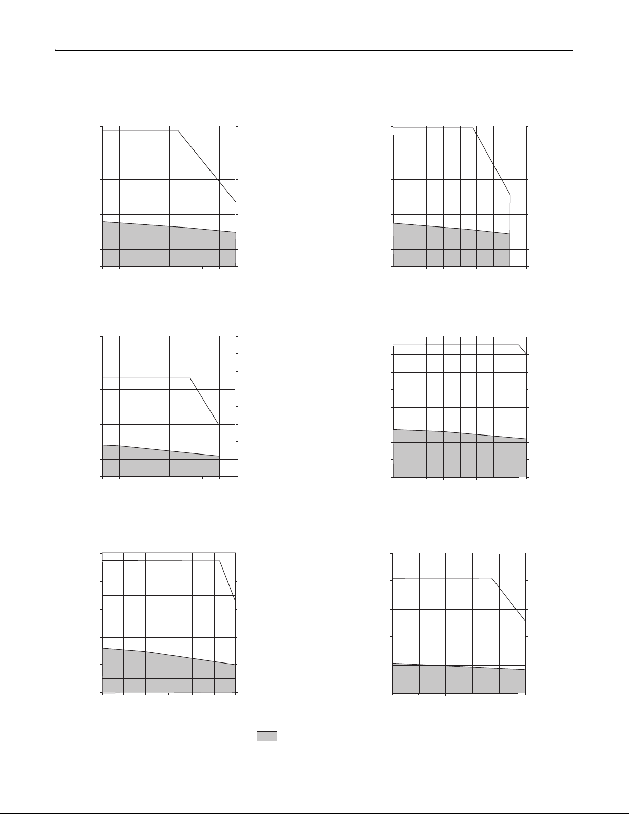
= Intermittent operating region
= Continuous operating region
= Drive operation with 400V AC rms input voltage
2094-BM01-S @ 250% or 2094-BM02-S @ 150%
and MPL-B330P
Kinetix 6000 Drive Rotary Performance Example with Peak Enhancement Feature
The peak current ratings of the Kinetix 6000 AM modules (series A, B, and C) are configured at the factory as 150% of continuous
current. You can program 400V-class (series B and C) AM modules, and the equivalent IAM (inverter) modules, to operate with up to
250% of continuous inverter current. Refer to
information.
Before your Kinetix 6000 drive can deliver enhanced-peak performance, you must enable the peak enhancement feature by
configuring your drive by using DriveExplorer™ or RSLogix 5000 software, or the Studio 5000 Logix Designer application.
Refer to the Kinetix 6000 Multi-axis Servo Drive User Manual, publication 2094-UM001
deceleration limit values, and paste them into the appropriate Axis Properties dialog box in RSLogix 5000 software or the
Logix Designer application.
For sizing your drive/motor combination when using series B or C drives with the peak enhancement feature, use Motion Analyzer
software, version 4.6 or later.
In this example, the MPL-B330P motor, usually paired with the 2094-BM02 (series A) AM module, is shown paired with
the 2094-BM01-S (series B or C) AM module. The two curves illustrate how the 2094-BM01-S (series B or C) drive, when
configured for 250% peak, can achieve full motor performance.
the Kinetix Servo Drives Technical Data, publication GMC-TD003, for more
, to recalculate torque and acceleration/
Rotary Motor Performance Specifications Example with Kinetix 6000 Drives
Motor
MPL-B330P 5000 6.10 4.18 (37)
Speed, max
rpm
System Continuous
Stall Current
A 0-pk
System Continuous
Stall Torque
N•m (lb•in)
System Peak
Stall Current
A 0-pk
13.0 8.0 (71)
19.0 11.1 (98)
System Peak
Stall Torque
N•m (lb•in)
12.0
Torque
(N•m)
10.0
8.0
6.0
4.0
2.0
0
0
Motor Rated
Output
kW
1.8
30001000
2000
Speed (rpm)
Kinetix 6000
400V-class Drives
2094-BM01-S @ 150%
2094-BM01-S @ 250%
2094-BM02-S @ 150%
106
88.5
70.8
53.1
35.4
17.7
0
5000
4000
Torque
(lb•in)
The 2094-BC07-M05-S and 2094-BM05-S (series B and C) modules are limited to 200% of continuous inverter current.
Rockwell Automation Publication GMC-RM003C-EN-P - September 2013 17
Kinetix 6000 and Kinetix 6200/6500 Drive Systems
IMPORTANT
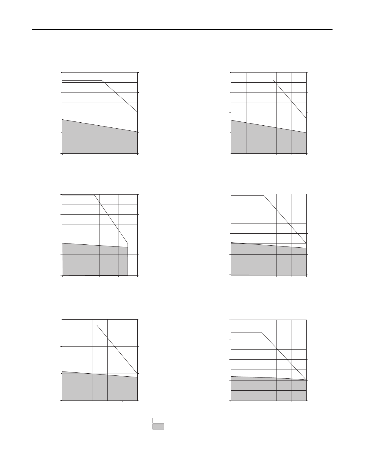
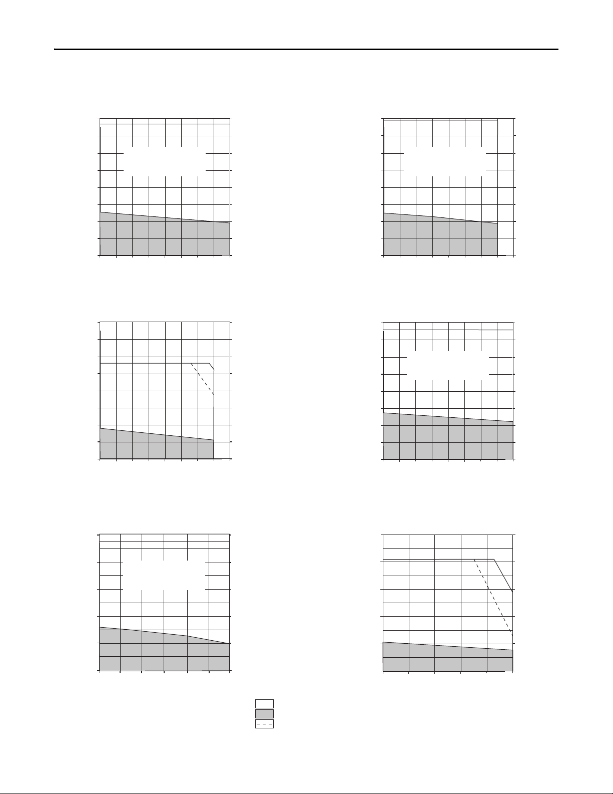
Kinetix 6000 (200V-class) Drives with MP-Series Low Inertia Motors
This section provides system combination information for the Kinetix 6000 (200V-class) drives when matched with
MP-Series™ low-inertia motors. Included are motor power/brake and feedback cable catalog numbers, system performance
specifications, and the optimum torque/speed curves.
The MP-Series low-inertia motors on this page are equipped with DIN connectors (specified by 7 in the catalog number) and are
not compatible with cables designed for motors equipped with bayonet connectors (specified by 2 in the catalog number). The
motors with bayonet connectors (for example, MPL-A310P-xx2xAA) are being discontinued and require 2090-XXNxMP (bayonet)
cables. For help with migration or to select bayonet cables, contact your Rockwell Automation sales representative.
Bulletin MPL Motor Cable Combinations
Motor Cat. No. (200V-class) Motor Power/Brake Cable Motor Feedback Cable
MPL-A1510V-xx7xAA, MPL-A1520U-xx7xAA, MPL-A1530U-xx7xAA
MPL-A210V-xx7xAA, MPL-A220T-xx7xAA, MPL-A230P-xx7xAA
MPL-A310F-xx7xAA, MPL-A310P-xx7xAA,
MPL-A320H-xx7xAA, MPL-A320P,-xx7xAA, MPL-A330P-xx7xAA
MPL-A420P-xx7xAA, MPL-A430H-xx7xAA
MPL-A4530F-xx7xAA, MPL-A4540C-xx7xAA
MPL-A430P-xx7xAA
MPL-A4530K-xx7xAA, MPL-A4540F-xx7xAA, MPL-A4560F-xx7xAA
MPL-A520K-xx7xAA
MPL-A540K-xx7xAA, MPL-A560F-xx7xAA
(1) Use low-profile connector kit (catalog number 2090-K6CK-D15M) with flying-lead cables on the drive end. Refer to Required Drive Accessories on page 4.
(2) Applies to Kinetix 6000 drives and MPL-A3xxx-M/S…MPL-A5xxx-M/S motors with absolute high-resolution feedback.
(3) Applies to Kinetix 6000 drives and MPL-A15xxx-V/E…MPL-A2xxx-V/E motors with absolute high-resolution feedback.
(4) Applies to Kinetix 6000 drives and MPL-A15xxx-H…MPL-A45xxx-H motors with incremental feedback.
For cable configuration illustrations and feature descriptions, by catalog number, refer to 2090-Series Motor/Actuator Cables Overview beginning on page 7.
Motor-end connector kits, and panel-mounted breakout components (drive end), are available for motor power/brake and feedback cables. Refer to Optional Drive Accessories on page 6
Cable len gth xx is in meters. Refer to the Kinetix Motion Accessories Technical Data, publication GMC-TD004
2090-CPxM7DF-16AAxx (standard, non-flex)
2090-CPxM7DF-16AFxx (continuous-flex)
2090-CPxM7DF-14AAxx (standard, non-flex)
2090-CPxM7DF-14AFxx (continuous-flex)
2090-CPxM7DF-10AAxx (standard, non-flex)
2090-CPxM7DF-10AFxx (continuous-flex)
20
M7DF-08AAxx (standard, non-flex)
90-CPx
2090-CPxM7DF-08AFxx (continuous-flex)
, for standard cable lengths.
2090-CFBM7DF-CEAAxx or
2090-CFBM7DD-CEAAxx (standard, non-flex)
2090-CFBM7DF-CEAFxx or
2090-CFBM7DD-CEAFxx (continuous-flex)
Absolute High-resolution Feedback
2090-XXNFMF-Sxx (standard, non-flex)
2090-CFBM7DF-CDAFxx (continuous-flex)
Incremental Feedback
(1)
(2) (3)
(4)
.
Bulletin MPL Motor Performance Specifications with Kinetix 6000 (200V-class) Drives
Rotary Motor
MPL-A1510V 8000 1.05 0.26 (2.3) 3.40 0.77 (6.8) 0.16 2094-AMP5-S
MPL-A1520U 7000 1.80 0.49 (4.3) 6.10 1.58 (13.9) 0.27 2094-AMP5-S
MPL-A1530U 7000 2.82 0.90 (8.0) 10.1 2.82 (24.9) 0.39 2094-AMP5-S
MPL-A210V 8000 3.09 0.55 (4.8) 10.2 1.52 (13.4) 0.37 2094-AMP5-S
MPL-A220T 6000 4.54 1.61 (14.2)
MPL-A230P 5000 5.40 2.10 (18.6)
Speed, max
rpm
System Continuous
Stall Current
A 0-pk
18 Rockwell Automation Publication GMC-RM003C-EN-P - September 2013
System Continuous
Stall Torque
N•m (lb•in)
System Peak
Stall Current
A 0-pk
10.5 3.45 (30.0)
15.5 4.74 (41.9) 2094-AM01-S
17.0 8.0 (70.8)
23.0 8.2 (73.0) 2094-AM02-S
System Peak
Stall Torque
N•m (lb•in)
Motor Rated Output
kW
0.62
0.86
Kinetix 6000
200V-class Drives
2094-AMP5-S
2094-AM01-S

Kinetix 6000 and Kinetix 6200/6500 Drive Systems
Bulletin MPL Motor Performance Specifications with Kinetix 6000 (200V-class) Drives (continued)
Rotary Motor
MPL-A310F 3000 3.24 1.58 (14.0) 9.30 3.61 (31.9) 0.46 2094-AMP5-S
MPL-A310P 5000 4.91 1.58 (14.0)
MPL-A320H 3500 6.10 3.05 (27.0)
MPL-A320P 5000
MPL-A330P 5000 12.0 4.18 (37.0)
MPL-A420P 5000 12.9 4.79 (42.3)
MPL-A430H 3500 12.2 6.21 (55.0)
MPL-A430P 5000
MPL-A4530F 2800 13.40 8.36 (74 .0)
MPL-A4530K 4000 19.50 8.13 (71.9)
MPL-A4540C 1500
MPL-A4540F 3000 18.40 10.19 (90.1)
MPL-A4560F 3000 22.0 14.1 (125)
MPL-A520K 4000 15.0 10.77 (9 5.2)
MPL-A540K 4000 41.5 19.42 (1 71) 73.4 31.3 (277) 5.5 2094-AM05-S
MPL-A560F 3000 42.0 27.39 (242) 73.4 39.6 (350) 5.3 2094-AM05-S
Speed, max
rpm
System Continuous
Stall Current
A 0-pk
8.50 2.88 (25.5) 17.0 5.07 (44.8)
9.00 3.05 (27.0) 29.5 7.91 (70.0) 2094-AM02-S
15.0 5.35 (47.3) 30.0 9.99 (88.3)
16.80 5.99 (52.9)
8.50 9.15 (80.9) 17.0 16.9 (150)
9.55 10.30 (91.1) 29.0 27.1 (239) 2094-AM02-S
System Continuous
Stall Torque
N•m (lb•in)
System Peak
Stall Current
A 0-pk
10.5 2.90 (25.6)
14.0 3.61 (31.9) 2094-AM01-S
17.0 7.13 (63.0)
19.3 7.91 (70.0) 2094-AM02-S
30.0 9.10 (80.5)
38.0 11.1 (98.2) 2094-AM03-S
30.0 9.67 (85.5)
46.0 13.6 (119) 2094-AM03-S
30.0 13.9 (123)
45.0 19.8 (175) 2094-AM03-S
49.0 15.4 (136) 2094-AM03-S
67.0 19.8 (175) 2094-AM05-S
30.0 15.8 (139)
42.0 20.3 (179) 2094-AM03-S
49.0 17.0 (150)
62.0 20.3 (179) 2094-AM05-S
49.0 23.6 (208)
58.0 27.1 (239) 2094-AM05-S
49.0 27.0 (239)
66.0 34.4 (305) 2094-AM05-S
49.0 19.3 (171)
65.0 24.2 (214) 2094-AM05-S
System Peak
Stall Torque
N•m (lb•in)
Motor Rated Output
kW
0.73
1.0
1.3
1.8
2.0
1.8
2.2
1.9
2.5
1.5
2.6
3.0
3.5
Kinetix 6000
200V-class Drives
2094-AMP5-S
2094-AM01-S
2094-AM01-S
2094-AM02-S
2094-AM02-S
2094-AM02-S
2094-AM02-S
2094-AM02-S
2094-AM03-S
2094-AM01-S
2094-AM03-S
2094-AM03-S
2094-AM03-S
Performance specification data and curves reflect nominal sys tem performance of a typical system with motor at 40 °C (104 °F) and drive at 50 °C (122 °F) ambient and rated line voltage. For additional
information on ambient and line conditions, refer to Motion Analyzer software.
Rockwell Automation Publication GMC-RM003C-EN-P - September 2013 19
Kinetix 6000 and Kinetix 6200/6500 Drive Systems
Torque
(N•m)
Torque
(lb•in)
Speed (rpm)
2000 4000 6000 80000
2094-AMP5-S and MPL-A1510V
0.800
0.700
0.600
0.500
0.400
0.300
0.200
0.100
0
7.08
6.19
5.31
4.42
3.54
2.65
1.77
0.88
0
Torque
(N•m)
Torque
(lb•in)
Speed (rpm)
2000 4000 6000 80000
2094-AMP5-S and MPL-A1520U
1.600
1.400
1.200
1.000
0.800
0.600
0.400
0.200
0
14.1
12.4
10.6
8.85
7.08
5.31
3.54
1.77
0
Torque
(N•m)
Torque
(lb•in)
Speed (rpm)
2000 4000 6000 80000
2094-AMP5-S and MPL-A1530U
4.00
3.50
3.00
2.50
2.00
1.50
1.00
0.50
0
35.4
30.9
26.5
22.1
17.7
13.3
8.84
4.42
0
Torque
(N•m)
Torque
(lb•in)
Speed (rpm)
2000 4000 6000 80000
2094-AMP5-S and MPL-A210V
1.600
1.400
1.200
1.000
0.800
0.600
0.400
0.200
0
14.1
12.4
10.6
8.85
7.08
5.31
3.54
1.77
0
Torque
(N•m)
Torque
(lb•in)
0
0
1.0
2.0
3.0
5.0
4.0
8.85
17.7
26.5
35.4
44.2
2094-AM01-S and MPL-A220T
Speed (rpm)
1000
2000 3000 40000 5000 6000
Torque
(N•m)
Torque
(lb•in)
2094-AM02-S and MPL-A230P
0
0
2.0
4.0
6.0
35.4
53.1
70.8
8.0
88.5
Speed (rpm)
0
3000
5000
40001000
2000
10.0
1.77
= Intermittent operating region
= Continuous operating region
Kinetix 6000 (200V-class) Drives/MP-Series Low Inertia Motor Curves
20 Rockwell Automation Publication GMC-RM003C-EN-P - September 2013
Kinetix 6000 and Kinetix 6200/6500 Drive Systems
Torque
(N•m)
Torque
(lb•in)
2094-AMP5-S and MPL-A310F
35.4
26.5
17.7
8.85
0
4.0
3.0
2.0
1.0
0
Speed (rpm)
30001000
2000
0
Torque
(N•m)
Torque
(lb•in)
Speed (rpm)
2094-AM02-S and MPL-A320H
70.8
53.1
35.4
17.7
0
0
2000
4000
8.0
6.0
4.0
2.0
0
30001000
Torque
(N•m)
Torque
(lb•in)
2094-AM03-S and MPL-A330P
Speed (rpm)
0
2000
4000
30001000
5000
12.0
10.0
8.0
6.0
4.0
2.0
0
106
88.5
70.8
53.1
35.4
17.7
0
Torque
(N•m)
Torque
(lb•in)
141
106
70.8
35.4
0
16.0
12.0
8.0
4.0
0
2094-AM03-S and MPL-A420P
Speed (rpm)
0
2000
4000
30001000
5000
= Intermittent operating region
= Continuous operating region
Kinetix 6000 (200V-class) Drives/MP-Series Low Inertia Motor Curves (continued)
2094-AM01-S and MPL-A310P
Torque
(N•m)
4.0
35.4
Torque
(lb•in)
Torque
(N•m)
3.0
2.0
1.0
8.0
7.0
6.0
5.0
4.0
3.0
2.0
1.0
0
0
2094-AM02-S and MPL-A320P
0
0
30001000
2000
Speed (rpm)
30001000
2000
Speed (rpm)
4000
4000
5000
5000
26.5
17.7
8.8.5
0
70.8
61.9
53.1
44.2
35.4
26.5
17.7
8.85
0
Torque
(lb•in)
Rockwell Automation Publication GMC-RM003C-EN-P - September 2013 21
Kinetix 6000 and Kinetix 6200/6500 Drive Systems
Torque
(N•m)
Torque
(lb•in)
0
0
5
10
15
25
20
44.2
88.5
133
177
221
Speed (rpm)
0
2000
4000
30001000
2094-AM03-S and MPL-A430H
Torque
(N•m)
Torque
(lb•in)
0
0
5
10
15
25
20
44.2
88.5
133
177
221
Speed (rpm)
30001000
2000
0
2094-AM03-S and MPL-A4530F
Torque
(N•m)
Torque
(lb•in)
2094-AM02-S and MPL-A4540C
30
25
20
15
10
5
0
265
221
177
133
88.5
44.2
0
Speed (rpm)
0 15001000500 1250750250
Torque
(N•m)
Torque
(lb•in)
2094-AM05-S and MPL-A4540F
30
25
20
15
10
5
0
265
221
177
133
88.5
44.2
0
Speed (rpm)
0 300020001000
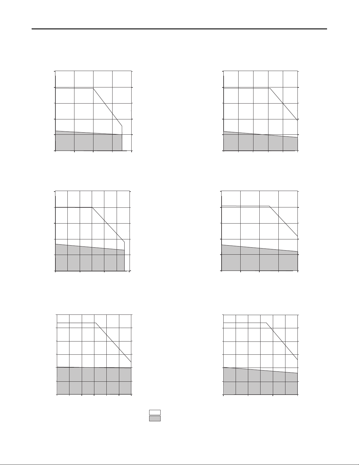
= Intermittent operating region
= Continuous operating region
Kinetix 6000 (200V-class) Drives/MP-Series Low Inertia Motor Curves (continued)
2094-AM05-S and MPL-A430P
25
Torque
(N•m)
20
221
177
Torque
(lb•in)
Torque
(N•m)
15
10
5
0
0
2094-AM05-S and MPL-A4530K
25
20
15
10
5
0
0
30001000
2000
Speed (rpm)
2000
Speed (rpm)
4000
30001000
5000
4000
133
88.5
44.2
0
221
177
133
88.5
44.2
0
Torque
(lb•in)
22 Rockwell Automation Publication GMC-RM003C-EN-P - September 2013
Kinetix 6000 and Kinetix 6200/6500 Drive Systems
Torque
(N•m)
Torque
(lb•in)
0
0
10
20
30
50
40
88.5
177
265
354
443
Speed (rpm)
0 300020001000
2094-AM05-S and MPL-A4560F
Torque
(N•m)
Torque
(lb•in)
Speed (rpm)
2094-AM05-S and MPL-A540K
0
2000
4000
32
24
16
8
0
30001000
283
212
141
70.8
0
= Intermittent operating region
= Continuous operating region
Kinetix 6000 (200V-class) Drives/MP-Series Low Inertia Motor Curves (continued)
2094-AM05-S and MPL-A520K
Torque
(N•m)
30
25
265
221
Torque
(lb•in)
Torque
(N•m)
4000
177
133
88.5
44.2
0
443
354
265
177
88.5
Torque
(lb•in)
20
15
10
5
0
0
2094-AM05-S and MPL-A560F
50
40
30
20
10
2000
Speed (rpm)
30001000
0
0 300020001000
Speed (rpm)
0
Rockwell Automation Publication GMC-RM003C-EN-P - September 2013 23

Kinetix 6000 and Kinetix 6200/6500 Drive Systems
IMPORTANT
IMPORTANT
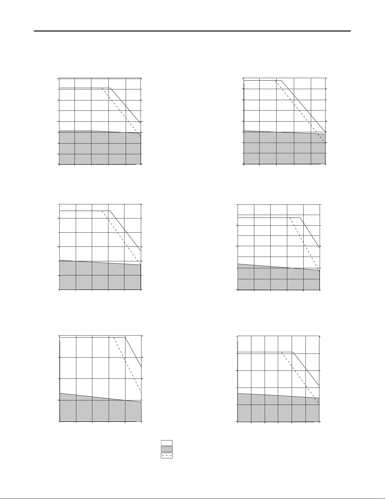
Kinetix 6000 and Kinetix 6200/6500 (400V-class) Drives
with MP-Series Low Inertia Motors
This section provides system combination information for the Kinetix 6000 and the Kinetix 6200/6500 (400V-class)
drives when matched with MP-Series low-inertia motors. Included are motor power/brake and feedback cable catalog
numbers, system performance specifications, and the optimum torque/speed curves.
When using Kinetix 6000 (series B or C) drives, configured for enhanced peak performance, you can usually achieve full motor
performance with a smaller drive. Kinetix 6200 and Kinetix 6500 drives are configured for enhanced peak performance by default.
Expect the same peak performance from Kinetix 6200/6500 drives as you get from Kinetix 6000 (series B or C) drives configured for
enhanced peak performance.
Refer to Kinetix Servo Drives Specifications Technical Data, publication GMC-TD003
The MP-Series low-inertia motors on this page are equipped with DIN connectors (specified by 7 in the catalog number) and are
not compatible with cables designed for motors equipped with bayonet connectors (specified by 2 in the catalog number). The
motors with bayonet connectors (for example, MPL-A310P-xx2xAA) are being discontinued and require 2090-XXNxMP (bayonet)
cables. For help with migration or to select bayonet cables, contact your Rockwell Automation sales representative.
, for more information.
Bulletin MPL Motor Cable Combinations
Motor Cat. No. (400V-class) Motor Power/Brake Cable Motor Feedback Cable
MPL-B1510V-xx7xAA, MPL-B1520U-xx7xAA, MPL-B1530U-xx7xAA
MPL-B210V-xx7xAA, MPL-B220T-xx7xAA, MPL-B230P-xx7xAA
MPL-B310P-xx7xAA, MPL-B320P-xx7xAA, MPL-B330P-xx7xAA
MPL-B420P-xx7xAA, MPL-B430P-xx7xAA
MPL-B4530F-xx7xAA, MPL-B4530K-xx7xAA,
MPL-B4540F-xx7xAA, MPL-B4560F-xx7xAA
MPL-B520K-xx7xAA
MPL-B540D-xx7xAA, MPL-B540K-xx7xAA, MPL-B560F-xx7xAA
MPL-B580F-xx7xAA, MPL-B580J-xx7xAA,
MPL-B640F-xx7xAA
MPL-B660F-xx7xAA, MPL-B680D-xx7xAA,
MPL-B960B-xx7xAA, MPL-B980B-xx7xAA
MPL-B680F-xx7xAA, MPL-B680H-xx7xAA,
MPL-B860D-xx7xAA, MPL-B880C-xx7xAA
MPL-B880D-xx7xAA 2090-CPxM7DF-04AAxx (standard, non-flex)
(1) Use low-profile connector kit (catalog number 2090-K6CK-D15M) with flying-lead cables on the drive end. Refer to Required Drive Accessories on page 4.
(2) Applies to Kinetix 6000 drives and MPL-B3xxx-M/S…MPL-B9xxx-M/S motors with absolute high-resolution feedback.
(3) Applies to Kinetix 6000 drives and MPL-B15xxx-V/E…MPL-B2xxx-V/E motors with absolute high-resolution feedback.
(4) Applies to Kinetix 6000 drives and MPL-B15xxx-H…MPL-B45xxx-H motors with incremental feedback.
(5) Applies to Kinetix 6000 drives and MPL-B3xxx-R…MPL-B45xxx-R motors with resolver feedback.
For cable configuration illustrations and feature descriptions, by catalog number, refer to 2090-Series Motor/Actuator Cables Overview beginning on page 7.
Motor-end connector kits, and panel-mounted breakout components (drive end), are available for motor power/brake and feedback cables. Refer to Optional Drive Accessories on page 6
Cable len gth xx is in meters. Refer to the Kinetix Motion Accessories Technical Data, publication GMC-TD004
2090-CPxM7DF-16AAxx (standard, non-flex)
2090-CPxM7DF-16AFxx (continuous-flex)
2090-CPxM7DF-14AAxx (standard, non-flex)
2090-CPxM7DF-14AFxx (continuous-flex)
2090-CPxM7DF-10AAxx (standard, non-flex)
2090-CPxM7
2090-CPxM7DF-08AAxx (standard, non-flex)
2090-CPxM7DF-08AFxx (continuous-flex)
2090-CPxM7DF-06AAxx (standard, non-flex)
DF-10AFxx (
, for standard cable lengths.
continuous-flex)
2090-CFBM7DF-CEAAxx or
2090-CFBM7DD-CEAAxx (standard, non-flex)
2090-CFBM7DF-CEAFxx or
2090-CFBM7DD-CEAFxx (continuous-flex)
Absolute High-resolution Feedback
2090-XXNFMF-Sxx (standard)
2090-CFBM7DF-CDAFxx (continuous-flex)
Incremental Feedback
2090-CFBM7DF-CEAAxx (standard, non-flex)
2090-CFBM7DF-CEAFxx (continuous-flex)
Resolver Feedback
(1)
(2) (3)
(4)
(5)
.
24 Rockwell Automation Publication GMC-RM003C-EN-P - September 2013

Kinetix 6000 and Kinetix 6200/6500 Drive Systems
Bulletin MPL Motor Performance Specifications with Kinetix 6200/6500 (400V-class) Drives
Rotary Motor
MPL-B1510V 8000 0.95 0.26 (2.3) 3.10 0.77 (6.8) 0.16 2094-BMP5-M
MPL-B1520U 7000 1.80 0.49 (4.3) 6.10 1.58 (13.9) 0.27 2094-BMP5-M
MPL-B1530U 7000 2.0 0.90 (8.0) 7.20 2.82 (24.9) 0.39 2094-BMP5-M
MPL-B210V 8000 1.75 0.55 (4.9) 5.80 1.52 (13.4) 0.37 2094-BMP5-M
MPL-B220T 6000 3 .30 1.61 (14.2)
MPL-B230P 5000 2.60 2.10 (18.6)
MPL-B310P 5000 2.4 1.6 (14.1) 7 .10 3.6 (32) 0.77 2094-BMP5-M
MPL-B320P 5000
MPL-B330P 5000
MPL-B420P 5000 6.3 4.74 (42)
MPL-B430P 5000
MPL-B4530F 3000
MPL-B4530K 4000
MPL-B4540F 3000
MPL-B4560F 3000
MPL-B520K 4000
MPL-B540D 2000
MPL-B540K 4 000 20.4 19.4 (171) 60.0 48.6 (430) 5.4 209 4-BM03-M
MPL-B560F 3000 20.6 26.8 (237) 6 8.0 67.8 (600) 5.5 2094-BM03-M
MPL-B580F 3000 26.0 34.0 (300)
MPL-B580J 3800
MPL-B640F 3000
MPL
0F 3000 38.5 48.0 (425) 96.0 101 (895) 6.1 2094-BM05-M
-B66
MPL-B680D 2000
MPL-B680F 3000 47.9 60.0 (531) 9 6.0 108 (960) 7.5 2094-BM05-M
MPL-B680H 3500 48.9 58.0 (513) 9 7.8 107 (947) 7.5 2094-BM05-M
Speed, max
rpm
System Continuous
Stall Current
A 0-pk
4.0 2.7 (23.9) 9.90 5.9 (52.2)
4.5 3.10 (27) 14.0 8.2 (72.5) 2094-BM01-M
4.0 2.7 (23.9) 9.90 6.8 (60.2)
6.1 4.18 (37) 19.0 11.1 (98) 2094-BM01-M
8.6 6.2 (54.9) 21.6 13.9 (123)
9.2 6.55 (58) 32.0 19.8 (175) 2094-BM02-M
4.0 4.9 (43.3) 9.90 11.0 (97.3)
6.7 8.36 (74) 21.0 20.3 (180) 2094-BM01-M
8.6 7.1 (62.8) 21.6 15.1 (133)
9.9 8.25 (73) 31.0 20.3 (179) 2094-BM02-M
8.6 9.5 (84.1) 21.6 20.9 (185)
9.1 10.20 (90) 29.0 27.1 (240) 2094-BM02-M
8.6 10.5 (92.9) 21.6 22.7 (201)
11.8 14.0 (124) 36.0 34.4 (304) 2094-BM02-M
8.6 7.9 (69.9) 21.6 16.6 (147)
11.5 10.7 (95) 33.0 23.2 (205) 2094-BM02-M
8.6 15.8 (139) 21.6 37.9 (335)
10.5 19.4 (172) 23.0 41.0 (362) 2094-BM02-M
30.0 31.7 (280) 75.0 67.0 (592)
32.0 34.0 (301) 94.0 81.0 (716) 2094-BM05-M
30.0 34.4 (304)
32.0 36.7 (325) 2094-BM05-M
30.0 55.4 (490) 75.0 125 (1105)
34.0 62.8 (556) 94.0 154 (1365) 2094-B M05-M
System Continuous
Stall Torque
N•m (lb•in)
System Peak
Stall Current
A 0-pk
9.90 4.12 (36.4)
11.3 4.74 (41.9) 209 4-BM01-M
9.90 7.24 (64.0)
11.3 8.20 (73.0) 209 4-BM01-M
21.6 13.1 (116)
22.0 13.5 (119) 2094-BM02-M
75.0 74.6 (660)
94.0 87.0 (770) 2094-BM05-M
65.0 72.3 (640) 6.1
System Peak
Stall Torque
N•m (lb•in)
Motor Rated
Output
kW
0.62
0.86
1.5
1.8
1.9
2.2
2.1
2.6
2.6
3.2
3.5
3.4
7.1
7.9
9.3
Kinetix 6200/
Kinetix 6500
400V-class Drives
2094-BMP5-M
2094-BMP5-M
2094-BMP5-M
2094-BMP5-M
2094-BM01-M
2094-BM01-M
2094-BMP5-M
2094-BM01-M
2094-BM01-M
2094-BM01-M
2094-BM01-M
2094-BM01-M
2094-BM03-M
2094-BM03-M
2094-BM03-M
2094-BM03-M
Rockwell Automation Publication GMC-RM003C-EN-P - September 2013 25
Kinetix 6000 and Kinetix 6200/6500 Drive Systems
Bulletin MPL Motor Performance Specifications with Kinetix 6200/6500 (400V-class) Drives (continued)
Rotary Motor
MPL-B860D 2000 47.3 83.0 (735) 95.5 152 (1350) 12.5 2094-BM05-M
MPL-B880C 1500 47.5 11 0 (973) 97.5 203 (1800) 12.6 2094-BM05-M
MPL-B880D 2000 48.9 79.9 (706) 96.0 147 (1300) 12.6 2094-BM05-M
MPL-B960B 1200 42.5 130 (1150) 94.0 231 (2050) 12.7 2094-BM05-M
MPL-B980B 1000 40.0 162 (1440) 94.0 278 (2460) 15.2 2094-BM05-M
Performance specification data and curves reflect nominal sys tem performance of a typical system with motor at 40 °C (104 °F) and drive at 50 °C (122 °F) ambient and rated line voltage. For additional
information on ambient and line conditions, refer to Motion Analyzer software.
Speed, max
rpm
System Continuous
Stall Current
A 0-pk
System Continuous
Stall Torque
N•m (lb•in)
System Peak
Stall Current
A 0-pk
System Peak
Stall Torque
N•m (lb•in)
Motor Rated
Output
kW
Kinetix 6200/
Kinetix 6500
400V-class Drives
Bulletin MPL Motor Performance Specifications with Kinetix 6000 (400V-class) Drives
Rotary Motor
MPL-B1510V 8000 0.95 0.26 (2.3) 3.10 0.77 (6.8) 0.16 BMP5-S @ 150 %
MPL-B1520U 7000 1.80 0.49 (4.3)
MPL-B1530U 7000 2.0 0.90 (8.0)
MPL-B210V 8000 1.75 0.55 (4.9) 5.80 1.52 (13.4) 0.37 BMP5-S @ 150%
MPL-B220T 6000 3.30 1.61 (14.2)
MPL-B230P 5000 2.60 2.10 (18.6)
MPL-B310P 5000 2.4 1.6 (14)
MPL-B320P 5000 4.5 3.10 (27)
MPL-B330P 5000 6.1 4.18 (37)
MPL-B420P 5000 6.3 4.74 (42)
MPL-B430P 5000 9.2 6.55 (58)
MPL-B4530F 3000 6.7 8.36 (74)
MPL-B4530K 4000 9.9 8.25 (73)
MPL-B4540F 3 000 9.1 10.20 (90)
MPL-B4560F 3 000 11.8 14.0 (124)
Speed, max
rpm
System Continuous
Stall Current
A 0-pk
System Continuous
Stall Torque
N•m (lb•in)
System Peak
Stall Current
A 0-pk
5.90 1.53 (13.3)
6.10 1.58 (13.9) BMP5-S @ 250%
5.90 2.34 (20.7)
7.20 2.82 (24.9) BMP5-S @ 250%
9.90 4.12 (36.4)
11.3 4.74 (41.9) BM01-S @ 150%
9.90 7.24 (64.0)
11.3 8.20 (73.0) BM01-S @ 150%
5.90 3.2 (28)
7.10 3.6 (32) BMP5-S @ 250%
13.0 7.5 (66)
14.0 8.2 (72.5) BM01-S @ 250%
13.0 8.0 (71)
19.0 11.1 (98) BM01-S @ 250%
13.0 13.1 (116)
21.8 13.4 (118) BM02-S @ 150%
22.0 13.5 (119) BM02-S @ 250%
21.8 14.4 (127)
32.0 19.8 (175) BM02-S @ 250%
13.0 13.9 (123)
21.0 20.3 (180) BM01-S @ 250%
21.8 15.5 (137)
31.0 20.3 (179) BM02-S @ 250%
21.8 21.4 (189)
29.0 27.1 (240) BM02-S @ 250%
21.8 23.3 (206)
36.0 34.4 (304) BM02-S @ 250%
System Peak
Stall Torque
N•m (lb•in)
Motor Rated Output
kW
0.27
0.39
0.62
0.86
0.77
1.5
1.8
1.9
2.2
2.1
2.6
2.6
3.2
Kinetix 6000
400V-class Drives
BMP5-S @ 150%
BMP5-S @ 150%
BMP5-S @ 250%
BMP5-S @ 250%
BMP5-S @ 150%
BM01-S @ 150%
BM01-S @ 150%
BM01-S @ 250%
BM02-S @ 150%
BM01-S @ 150%
BM02-S @ 150%
BM02-S @ 150%
BM02-S @ 150%
26 Rockwell Automation Publication GMC-RM003C-EN-P - September 2013

Kinetix 6000 and Kinetix 6200/6500 Drive Systems
Bulletin MPL Motor Performance Specifications with Kinetix 6000 (400V-class) Drives (continued)
Rotary Motor
MPL-B520K 4000 11.5 10.7 (95)
MPL-B540D 2000 10.5 19.4 (172)
MPL-B540K 4000 20.4 19.4 (171)
MPL-B560F 3000 20.9 26.8 (237)
MPL-B580F 3000 26.1 34.0 (300)
MPL-B580J 3800 32.0 34.0 (301)
MPL-B640F 3000
MPL-B660F 3000 38.5 48.0 (425)
MPL-B680D 2000
MPL-B680F 3000 47.9 60.0 (531)
MPL-B680H 3500 48.9 58.0 (513) 97.8 107 (947) 7.5 B M05-S @ 200%
MPL-B860D 2000 47.3 83.0 (735)
MPL-B880C 1500 47.5 110 (973)
MPL-B880D 2000 48.9 79.9 (706) 96.0 147 (1300) 12.6 BM05-S @ 200%
MPL-B960B 1200 42.5 130 (1150)
MPL-B980B 1000 40.0 162 (1440)
Speed, max
rpm
System Continuous
Stall Current
A 0-pk
30.0
32.0 36.7 (325) BM05-S @ 150%
30.0 55.4 (490) 75.0 125 (1105)
34.0 62.8 (556)
System Continuous
Stall Torque
N•m (lb•in)
34.4 (304) 4 5.0 50.4 (446)
34.4 (304)
System Peak
Stall Current
A 0-pk
21.8 17.0 (150)
33.0 23.2 (205) BM02-S @ 250%
21.8 38.8 (343)
23.0 41.0 (362) BM02-S @ 250%
45.0 38.1 (337)
60.0 48.6 (430) BM03-S @ 250%
45.0 49.3 (436)
68.0 67.8 (600) BM03-S @ 250%
75.0 74.6 (660)
73.4 73.5 (650) BM05-S @ 150%
94.0 87.0 (770) BM05-S @ 200%
73.4 66.6 (589)
94.0 81.0 (716) BM05-S @ 200%
65.0 72.3 (640)
73.4 81.0 (716)
96.0 101 (895) BM05-S @ 200%
73.4 124 (1098) BM05-S @ 150%
94.0 152 (1350) BM05-S @ 200%
73.4 85.4 (755)
96.0 108 (960) BM05-S @ 200%
73.4 120 (1065)
95.5 152 (1350) BM05-S @ 200%
73.4 157 (1387)
97.5 203 (1800) BM05-S @ 200%
73.4 190 (1684)
94.0 231 (2050) BM05-S @ 200%
73.4 235 (2077)
94.0 278 (2460) BM05-S @ 200%
System Peak
Stall Torque
N•m (lb•in)
Motor Rated Output
kW
3.5
3.4
5.4
5.5
7.1
7.9
6.1
6.1
9.3
7.5
12.5
12.6
12.7
15.2
Kinetix 6000
400V-class Drives
BM02-S @ 150%
BM02-S @ 150%
BM03-S @ 150%
BM03-S @ 150%
BM03-S @ 250%
BM05-S @ 150%
BM03-S @ 150%
BM03-S @ 250%
BM05-S @ 150%
BM03-S @ 250%
BM05-S @ 150%
BM05-S @ 150%
BM05-S @ 150%
BM05-S @ 150%
BM05-S @ 150%
Performance specification data and curves reflect nominal sys tem performance of a typical system with motor at 40 °C (104 °F) and drive at 50 °C (122 °F) ambient and rated line voltage. For additional
information on ambient and line conditions, refer to Motion Analyzer software.
Rockwell Automation Publication GMC-RM003C-EN-P - September 2013 27
Kinetix 6000 and Kinetix 6200/6500 Drive Systems
Torque
(N•m)
Torque
(lb•in)
Speed (rpm)
2000 4000 6000 80000
2094-BMP5-S @ 150% or 2094-BMP5-M
and MPL-B1510V
0.800
0.700
0.600
0.500
0.400
0.300
0.200
0.100
0
7.08
6.19
5.31
4.42
3.54
2.65
1.77
0.88
0
Peak curve represents
460V and 400V inputs
Torque
(N•m)
Torque
(lb•in)
Speed (rpm)
2000 4000 6000 80000
2094-BMP5-S @ 250% or 2094-BMP5-M
and MPL-B1530U
4.00
3.50
3.00
2.50
2.00
1.50
1.00
0.50
0
35.4
30.9
26.5
22.1
17.7
13.3
8.84
4.42
0
Torque
(N•m)
Torque
(lb•in)
Speed (rpm)
2000 4000 6000 80000
2094-BMP5-S @ 150% or 2094-BMP5-M
and MPL-B210V
1.600
1.400
1.200
1.000
0.800
0.600
0.400
0.200
0
14.1
12.4
10.6
8.85
7.08
5.31
3.54
1.77
0
Peak curve represents
460V and 400V inputs
Torque
(N•m)
Torque
(lb•in)
0
0
1.0
2.0
3.0
5.0
4.0
8.85
17.7
26.5
35.4
44.2
2094-BM01-S @ 150% or 2094-BM01-M
and MPL-B220T
Speed (rpm)
1000
2000 3000 40000 5000
6000
Peak curve represents
460V and 400V inputs
= Intermittent operating region
= Continuous operating region
= Drive operation with 400V AC rms input voltage
Kinetix 6000 and Kinetix 6200/6500 (400V-class) Drives/MP-Series Low Inertia Motor Curves
2094-BMP5-S @ 250% or 2094-BMP5-M
and MPL-B1520U
Peak curve represents
460V and 400V inputs
2000 4000 6000 80000
Speed (rpm)
Torque
(N•m)
1.600
1.400
1.200
1.000
0.800
0.600
0.400
0.200
0
14.1
12.4
10.6
8.85
7.08
5.31
3.54
1.77
0
Torque
(lb•in)
Torque
(N•m)
28 Rockwell Automation Publication GMC-RM003C-EN-P - September 2013
2094-BM01-S @ 150% or 2094-BM01-M
and MPL-B230P
10.0
8.0
6.0
4.0
2.0
0
0
2000
Speed (rpm)
3000
88.5
Torque
(lb•in)
70.8
53.1
35.4
1.77
0
5000
40001000
Kinetix 6000 and Kinetix 6200/6500 Drive Systems
1000 2000 3000 4000
0
0
0
17.7
35.4
0.5
1.0
1.5
2.0
2.5
3.0
3.5
4.0
4.42
8.85
13.3
22.1
26.5
31.0
5000
Torque
(N•m)
Torque
(lb•in)
Speed (rpm)
2094-BMP5-S @ 250% or 2094-BMP5-M
and MPL-B310P
Torque
(N•m)
Torque
(lb•in)
Speed (rpm)
0
2000
4000
30001000
5000
12.0
10.0
8.0
6.0
4.0
2.0
0
106
88.5
70.8
53.1
35.4
17.7
0
2094-BM01-S @ 250% or 2094-BM01-M
and MPL-B330P
Torque
(N•m)
Torque
(lb•in)
2094-BM02-S @ 250% or 2094-BM02-M
and MPL-B430P
0
0
5
10
15
44
88
133
20
177
Speed (rpm)
0
3000
5000
40001000
2000
= Intermittent operating region
= Continuous operating region
= Drive operation with 400V AC rms input voltage
Kinetix 6000 and Kinetix 6200/6500 (400V-class) Drives/MP-Series Low Inertia Motor Curves (continued)
2094-BM01-S @ 250% or 2094-BM01-M
Torque
(N•m)
8.0
and MPL-B320P
7.0
70.8
61.9
Torque
(lb•in)
Torque
(N•m)
6.0
5.0
4.0
3.0
2.0
1.0
0
1000 2000 3000 4000
0
Speed (rpm)
2094-BM02-S @ 250% or 2094-BM02-M
16
12
8
4
and MPL-B420P
5000
141
106
70.8
35.4
53.1
44.2
35.4
26.5
17.7
8.85
0
Torque
(lb•in)
0
0
2094-BM01-S @ 250% or 2094-BM01-M
25
Torque
(N•m)
20
15
10
Rockwell Automation Publication GMC-RM003C-EN-P - September 2013 29
5
0
and MPL-B4530F
500
1000 1500 20000 2500
30001000
2000
Speed (rpm)
Speed (rpm)
4000
0
5000
221
177
133
88.5
44.2
0
3000
Torque
(lb•in)
Kinetix 6000 and Kinetix 6200/6500 Drive Systems
Torque
(N•m)
Torque
(lb•in)
0
0
5
10
15
25
20
44.2
88.5
133
177
221
2094-BM02-S @ 250% or 2094-BM02-M
and MPL-B4530K
Speed (rpm)
0
2000
4000
30001000
Torque
(N•m)
Torque
(lb•in)
2094-BM02-S @ 250% or 2094-BM02-M
and MPL-B4560F
0
0
10
20
30
88.5
177
265
40
354
Speed (rpm)
500
1000 1500 20000 2500
3000
Torque
(N•m)
Torque
(lb•in)
0
0
5
10
15
25
20
44.2
88.5
133
177
221
2094-BM02-S @ 250% or 2094-BM02-M
and MPL-B520K
Speed (rpm)
0
2000
4000
30001000
Torque
(N•m)
Torque
(lb•in)
0
0
10
20
30
50
40
88.5
177
265
354
2094-BM02-S @ 250% or 2094-BM02-M
and MPL-B540D
442
Speed (rpm)
0
1000
2000
1500500
= Intermittent operating region
= Continuous operating region
= Drive operation with 400V AC rms input voltage
Kinetix 6000 and Kinetix 6200/6500 (400V-class) Drives/MP-Series Low Inertia Motor Curves (continued)
2094-BM02-S @ 250% or 2094-BM02-M
Torque
(N•m)
30
and MPL-B4540F
25
265
221
Torque
(lb•in)
20
15
10
5
0
2500
0
500 1500
1000
Speed (rpm)
2000
177
133
88.5
44.2
0
3000
Torque
(N•m)
30 Rockwell Automation Publication GMC-RM003C-EN-P - September 2013
2094-BM03-S @ 250% or 2094-BM03-M
50
40
30
20
10
0
0
and MPL-B540K
2000
Speed (rpm)
442
Torque
(lb•in)
354
265
177
88.5
30001000
0
4000
Loading...