


 Loading...
User Manual
PowerFlex 20-HIM-A6 and 20-HIM-C6S HIM
(Human Interface Module)
FRN 1.xxx - 2.xxx

Important User Information
Solid-state equipment has operational characteristics differing from those of electromechanical equipment. Safety Guidelines for the Application, Installation and Maintenance of Solid State Controls (publication SGI-1.1 available from your local Rockwell Automation sales office or online at http://www.rockwellautomation.com/literature/) describes some important differences between solid-state equipment and hard-wired electromechanical devices. Because of this difference, and also because of the wide variety of uses for solid-state equipment, all persons responsible for applying this equipment must satisfy themselves that each intended application of this equipment is acceptable.
In no event will Rockwell Automation, Inc. be responsible or liable for indirect or consequential damages resulting from the use or application of this equipment.
The examples and diagrams in this manual are included solely for illustrative purposes. Because of the many variables and requirements associated with any particular installation, Rockwell Automation, Inc. cannot assume responsibility or liability for actual use based on the examples and diagrams.
No patent liability is assumed by Rockwell Automation, Inc. with respect to use of information, circuits, equipment, or software described in this manual.
Reproduction of the contents of this manual, in whole or in part, without written permission of Rockwell Automation, Inc., is prohibited.
Throughout this manual, when necessary, we use notes to make you aware of safety considerations.
WARNING: Identifies information about practices or circumstances that can cause an explosion in a hazardous environment, which may lead to personal injury or death, property damage, or economic loss.
ATTENTION: Identifies information about practices or circumstances that can lead to personal injury or death, property damage, or economic loss. Attentions help you identify a hazard, avoid a hazard, and recognize the consequence.
SHOCK HAZARD: Labels may be on or inside the equipment, for example, a drive or motor, to alert people that dangerous voltage may be present.
BURN HAZARD: Labels may be on or inside the equipment, for example, a drive or motor, to alert people that surfaces may reach dangerous temperatures.
IMPORTANT Identifies information that is critical for successful application and understanding of the product.
Allen-Bradley, Rockwell Software, Rockwell Automation, TechConnect, and PowerFlex are trademarks of Rockwell Automation, Inc.
Trademarks not belonging to Rockwell Automation are property of their respective companies.

Summary of Changes
New and Updated
Information
This manual contains new and updated information.
This table contains the changes made to this revision.
Topic |
Page |
|
|
Revised steps in various procedures to add clarity. |
Throughout |
|
manual |
|
|
Rockwell Automation Publication 20HIM-UM001D-EN-P - February 2013 |
3 |

Summary of Changes
Notes:
4 |
Rockwell Automation Publication 20HIM-UM001D-EN-P - February 2013 |

|
Table of Contents |
|
Preface |
Conventions Used in This Manual . . . . . . . . . . . . . . . . . . . . . . . . . . . . . . . . . |
9 |
|
Rockwell Automation Support . . . . . . . . . . . . . . . . . . . . . . . . . . . . . . . . . . . . . |
9 |
|
Local Product Support . . . . . . . . . . . . . . . . . . . . . . . . . . . . . . . . . . . . . . . . . |
9 |
|
Technical Product Assistance. . . . . . . . . . . . . . . . . . . . . . . . . . . . . . . . . . . |
9 |
|
Additional Resources . . . . . . . . . . . . . . . . . . . . . . . . . . . . . . . . . . . . . . . . . . . . . |
10 |
|
Chapter 1 |
|
Getting Started |
HIM Types . . . . . . . . . . . . . . . . . . . . . . . . . . . . . . . . . . . . . . . . . . . . . . . . . . . . . . |
11 |
|
Features . . . . . . . . . . . . . . . . . . . . . . . . . . . . . . . . . . . . . . . . . . . . . . . . . . . . . . . . . |
11 |
|
Compatible Products . . . . . . . . . . . . . . . . . . . . . . . . . . . . . . . . . . . . . . . . . . . . . |
12 |
|
Safety Precautions . . . . . . . . . . . . . . . . . . . . . . . . . . . . . . . . . . . . . . . . . . . . . . . . |
12 |
|
Chapter 2 |
|
Installing the HIM |
Installing the 20-HIM-A6 HIM . . . . . . . . . . . . . . . . . . . . . . . . . . . . . . . . . . . |
14 |
|
In the Drive HIM Bezel . . . . . . . . . . . . . . . . . . . . . . . . . . . . . . . . . . . . . . . |
14 |
|
Using Drive Port 2 Connection for Hand-Held Operation . . . . . . |
16 |
|
In a Remote-Mount HIM Bezel (20-HIM-B1). . . . . . . . . . . . . . . . . . |
17 |
|
Installing the 20-HIM-C6S HIM. . . . . . . . . . . . . . . . . . . . . . . . . . . . . . . . . . |
18 |
|
Removing the HIM . . . . . . . . . . . . . . . . . . . . . . . . . . . . . . . . . . . . . . . . . . . . . . |
20 |
|
Chapter 3 |
|
HIM Components |
HIM Keypad . . . . . . . . . . . . . . . . . . . . . . . . . . . . . . . . . . . . . . . . . . . . . . . . . . . . |
21 |
|
Soft Keys . . . . . . . . . . . . . . . . . . . . . . . . . . . . . . . . . . . . . . . . . . . . . . . . . . . . |
21 |
|
Navigation and Number Keys . . . . . . . . . . . . . . . . . . . . . . . . . . . . . . . . . |
22 |
|
Single-function Keys . . . . . . . . . . . . . . . . . . . . . . . . . . . . . . . . . . . . . . . . . . |
23 |
|
LCD Display Elements . . . . . . . . . . . . . . . . . . . . . . . . . . . . . . . . . . . . . . . . . . . |
24 |
|
Status Bar . . . . . . . . . . . . . . . . . . . . . . . . . . . . . . . . . . . . . . . . . . . . . . . . . . . . |
24 |
|
Data Area. . . . . . . . . . . . . . . . . . . . . . . . . . . . . . . . . . . . . . . . . . . . . . . . . . . . |
24 |
|
Soft Key Labels . . . . . . . . . . . . . . . . . . . . . . . . . . . . . . . . . . . . . . . . . . . . . . . |
25 |
|
Main Screens . . . . . . . . . . . . . . . . . . . . . . . . . . . . . . . . . . . . . . . . . . . . . . . . . . . . |
26 |
|
Status Screen . . . . . . . . . . . . . . . . . . . . . . . . . . . . . . . . . . . . . . . . . . . . . . . . . |
26 |
|
Process Screen. . . . . . . . . . . . . . . . . . . . . . . . . . . . . . . . . . . . . . . . . . . . . . . . |
27 |
|
Control Screen . . . . . . . . . . . . . . . . . . . . . . . . . . . . . . . . . . . . . . . . . . . . . . . |
28 |
|
Folder Screens. . . . . . . . . . . . . . . . . . . . . . . . . . . . . . . . . . . . . . . . . . . . . . . . |
29 |
|
Fault Display Screen . . . . . . . . . . . . . . . . . . . . . . . . . . . . . . . . . . . . . . . . . . |
30 |
Rockwell Automation Publication 20HIM-UM001D-EN-P - February 2013 |
5 |

Table of Contents |
|
|
|
Chapter 4 |
|
Using the HIM |
Initial HIM Operation on New Drive Powerup. . . . . . . . . . . . . . . . . . . . . |
31 |
|
Selecting Display Contrast . . . . . . . . . . . . . . . . . . . . . . . . . . . . . . . . . . . . . . . . |
32 |
|
Setting the Date/Time for PowerFlex 750-Series Drives . . . . . . . . . . . . . |
33 |
|
Creating a User-Defined Drive/Peripheral Name . . . . . . . . . . . . . . . . . . . |
35 |
|
Customizing the Process Screen . . . . . . . . . . . . . . . . . . . . . . . . . . . . . . . . . . . |
36 |
|
Selecting Multi-Line or Single-Line View . . . . . . . . . . . . . . . . . . . . . . . |
36 |
|
Changing Displayed Items, Adding a Scale Factor, |
|
|
or Customizing Text . . . . . . . . . . . . . . . . . . . . . . . . . . . . . . . . . . . . |
37 |
|
Resetting the Drive/Peripherals . . . . . . . . . . . . . . . . . . . . . . . . . . . . . . . . . . . |
38 |
|
Setting Factory Defaults . . . . . . . . . . . . . . . . . . . . . . . . . . . . . . . . . . . . . . . . . . |
38 |
|
Setting PowerFlex 750-Series Drives/Peripherals |
|
|
to Factory Defaults. . . . . . . . . . . . . . . . . . . . . . . . . . . . . . . . . . . . . . |
38 |
|
Setting PowerFlex 7-Class Drives/Peripherals |
|
|
to Factory Defaults. . . . . . . . . . . . . . . . . . . . . . . . . . . . . . . . . . . . . . |
39 |
|
Setting Display Flashing for Fault Indication . . . . . . . . . . . . . . . . . . . . . . . |
40 |
|
Setting Display Flashing for Alarm Indication . . . . . . . . . . . . . . . . . . . . . . |
41 |
|
Viewing/Editing Drive or Peripheral Parameters . . . . . . . . . . . . . . . . . . . . |
42 |
|
Selecting File-Group-Parameter or Linear List View . . . . . . . . . . . . . |
42 |
|
Direct Parameter Access Method . . . . . . . . . . . . . . . . . . . . . . . . . . . . . . |
42 |
|
Alternate Linear List Access Method . . . . . . . . . . . . . . . . . . . . . . . . . . . |
43 |
|
Viewing/Clearing Drive Faults or Alarms . . . . . . . . . . . . . . . . . . . . . . . . . . |
44 |
|
Viewing Peripheral Diagnostic Items. . . . . . . . . . . . . . . . . . . . . . . . . . . . . . . |
45 |
|
Viewing/Clearing Peripheral Events . . . . . . . . . . . . . . . . . . . . . . . . . . . . . . . |
46 |
|
Checking Drive and Peripheral Firmware Revisions . . . . . . . . . . . . . . . . . |
47 |
|
Using the CopyCat Function . . . . . . . . . . . . . . . . . . . . . . . . . . . . . . . . . . . . . |
48 |
|
Creating CopyCat Files . . . . . . . . . . . . . . . . . . . . . . . . . . . . . . . . . . . . . . . |
48 |
|
Renaming CopyCat Files. . . . . . . . . . . . . . . . . . . . . . . . . . . . . . . . . . . . . . |
49 |
|
Deleting CopyCat Files . . . . . . . . . . . . . . . . . . . . . . . . . . . . . . . . . . . . . . . |
51 |
|
Changing PowerFlex 750-Series Drive Parameter Associations . . . . . . . |
52 |
|
Using Individual Screen Entry Method . . . . . . . . . . . . . . . . . . . . . . . . . |
52 |
|
Using Direct Numeric Entry Method . . . . . . . . . . . . . . . . . . . . . . . . . . |
54 |
|
Linking Parameters in PowerFlex 700/700S Drives . . . . . . . . . . . . . . . . . |
55 |
|
Establishing a Link . . . . . . . . . . . . . . . . . . . . . . . . . . . . . . . . . . . . . . . . . . . |
55 |
|
Deleting an Established Link . . . . . . . . . . . . . . . . . . . . . . . . . . . . . . . . . . |
56 |
|
Using a Password. . . . . . . . . . . . . . . . . . . . . . . . . . . . . . . . . . . . . . . . . . . . . . . . . |
57 |
|
Setting/Changing the Password. . . . . . . . . . . . . . . . . . . . . . . . . . . . . . . . |
57 |
|
Changing Password-protected Drive/Peripheral Parameters. . . . . . |
58 |
|
Disabling Password Protection. . . . . . . . . . . . . . . . . . . . . . . . . . . . . . . . . |
59 |
|
Initiating PowerFlex 750-Series Drive Port Verification . . . . . . . . . . . . . |
60 |
|
Conflict Types . . . . . . . . . . . . . . . . . . . . . . . . . . . . . . . . . . . . . . . . . . . . . . . |
60 |
|
Resolving ‘Changed’ or ‘Requires Configuration’ Conflicts. . . . . . . |
61 |
|
Resolving ‘Not Functioning’, ‘Not Supported’, |
|
|
or ‘Invalid Duplicate’ Conflicts. . . . . . . . . . . . . . . . . . . . . . . . . . . |
61 |
|
Changing Language for the Display Text . . . . . . . . . . . . . . . . . . . . . . . . . . . |
62 |
|
Updating the HIM Firmware or Language . . . . . . . . . . . . . . . . . . . . . . . . . |
63 |
6 |
Rockwell Automation Publication 20HIM-UM001D-EN-P - February 2013 |

|
|
Table of Contents |
|
Appendix A |
|
Specifications |
Communications. . . . . . . . . . . . . . . . . . . . . . . . . . . . . . . . . . . . . . . . . |
. . . . . . . . 65 |
|
Electrical . . . . . . . . . . . . . . . . . . . . . . . . . . . . . . . . . . . . . . . . . . . . . . . . |
. . . . . . . . 65 |
|
Mechanical . . . . . . . . . . . . . . . . . . . . . . . . . . . . . . . . . . . . . . . . . . . . . . . |
. . . . . . . 65 |
|
Environmental . . . . . . . . . . . . . . . . . . . . . . . . . . . . . . . . . . . . . . . . . . . . |
. . . . . . . 65 |
|
Regulatory Compliance . . . . . . . . . . . . . . . . . . . . . . . . . . . . . . . . . . . . |
. . . . . . . 66 |
|
Appendix B |
|
HIM Parameters |
Parameter List . . . . . . . . . . . . . . . . . . . . . . . . . . . . . . . . . . . . . . . . . . . . |
. . . . . . . 67 |
|
Appendix C |
|
History of Changes |
20HIM-UM001C-EN-P, January 2012 . . . . . . . . . . . . . . . . . . . . . |
. . . . . . . 69 |
|
20HIM-UM001B-EN-P, October 2010 . . . . . . . . . . . . . . . . . . . . |
. . . . . . . 70 |
|
20HIM-UM001A-EN-P, January 2009 . . . . . . . . . . . . . . . . . . . . . |
. . . . . . . 70 |
|
Index |
|
Rockwell Automation Publication 20HIM-UM001D-EN-P - February 2013 |
7 |

Table of Contents
Notes:
8 |
Rockwell Automation Publication 20HIM-UM001D-EN-P - February 2013 |

Preface
Conventions Used in This
Manual
Rockwell Automation
Support
This manual provides information about the enhanced PowerFlex 20-HIM-A6 and 20-HIM-C6S Human Interface Modules, and using them with PowerFlex 750-Series drives and PowerFlex® 7-Class drives.
The following conventions are used throughout this manual:
•Parameter names are shown in the format Parameter xx - [*]. The xx represents the parameter number. The * represents the parameter name— for example Parameter 01 - [Port Number].
•The HIM or drive firmware revision number (FRN) is displayed as FRN X.xxx, where ‘X’ is the major revision number and ‘xxx’ is the minor revision number.
Rockwell Automation offers support services worldwide, with over 75 sales and support offices, over 500 authorized distributors, and over 250 authorized systems integrators located through the United States alone. In addition, Rockwell Automation representatives are in every major country in the world.
Local Product Support
Contact your local Rockwell Automation representative for the following:
•Sales and order support
•Product technical training
•Warranty support
•Support service agreements
Technical Product Assistance
For technical assistance, please review the information in Chapter 4, Using the HIM, first. If you still have problems, then access the Allen-Bradley Technical Support website at http://www.ab.com/support/abdrives or contact Rockwell Automation.
Rockwell Automation Publication 20HIM-UM001D-EN-P - February 2013 |
9 |

Preface
Additional Resources
These documents contain additional information concerning related products from Rockwell Automation.
Resource |
Description |
|
|
|
|
PowerFlex 750-Series AC Drive Installation Instructions, publication 750-IN001 |
Information on installing and programming PowerFlex 750-Series AC drives |
|
|
|
|
PowerFlex 750-Series AC Drives Programming Manual, publication 750-PM001 |
|
|
|
|
|
PowerFlex 750-Series AC Drives Technical Data, publication 750-TD001 |
|
|
|
|
|
PowerFlex 70 User Manual, publication 20A-UM001 |
Information on installing and programming PowerFlex 70 standard control |
|
|
and enhanced control drives. |
|
PowerFlex 70/700 Reference Manual, publication PFLEX-RM001 |
||
|
||
|
|
|
PowerFlex 70 Enhanced Control and 700 Vector Control Reference Manual, publication PFLEX-RM004 |
|
|
|
|
|
PowerFlex 700 Series A User Manual, publication 20B-UM001 |
Information on installing and programming PowerFlex 700 standard control |
|
|
and vector control Series A drives, and PowerFlex 700 vector control Series B |
|
PowerFlex 700 Series B User Manual, publication 20B-UM002 |
||
drives. |
||
|
|
|
PowerFlex 70/700 Reference Manual, publication PFLEX-RM001 |
|
|
|
|
|
PowerFlex 70 Enhanced Control and 700 Vector Control Reference Manual, publication PFLEX-RM004 |
|
|
|
|
|
PowerFlex 700H Installation Instructions, publication PFLEX-IN006 |
Information on installing and programming PowerFlex 700H drives. |
|
|
|
|
PowerFlex 700H Programming Manual, publication 20C-PM001 |
|
|
|
|
|
PowerFlex 700S with Phase I Control Installation Manual (Frames 1…6), publication 20D-IN024 |
Information on installing and programming PowerFlex 700S drives. |
|
|
|
|
PowerFlex 700S with Phase I Control Installation Manual (Frames 9 and 10), publication PFLEX-IN006 |
|
|
|
|
|
PowerFlex 700S with Phase I Control User Manual (All Frame Sizes), publication 20D-UM001 |
|
|
|
|
|
PowerFlex 700S with Phase I Control Reference Manual, publication PFLEX-RM002 |
|
|
|
|
|
PowerFlex 700S with Phase II Control Installation Manual (Frames 1…6), publication 20D-IN024 |
|
|
|
|
|
PowerFlex 700S with Phase II Control Installation Manual (Frames 9…14), publication PFLEX-IN006 |
|
|
|
|
|
PowerFlex 700S with Phase II Control Programming Manual (All Frame Sizes), publication 20D-PM001 |
|
|
|
|
|
PowerFlex 700S with Phase II Control Reference Manual, publication PFLEX-RM003 |
|
|
|
|
|
PowerFlex 700L User Manual, publication 20L-UM001 |
Information on installing and programming PowerFlex 700L Liquid-Cooled |
|
|
AC drives. |
|
|
|
|
PowerFlex Digital DC Drive User Manual, publication 20P-UM001 |
Information on installing and programming PowerFlex Digital DC drives. |
|
|
|
You can view or download publications at http:// literature.rockwellautomation.com. To order paper copies of technical documentation, contact your local Allen-Bradley distributor or Rockwell Automation sales representative.
To find your local Rockwell Automation distributor or sales representative, visit
http://www.rockwellautomation.com/locations.
For information such as firmware updates or answers to drive-related questions, go to the Drives Service & Support website at http://www.ab.com/support/ abdrives and click the Downloads or Knowledgebase link.
10 |
Rockwell Automation Publication 20HIM-UM001D-EN-P - February 2013 |
Chapter 1
Getting Started
HIM Types
Features
The PowerFlex 20-HIM-A6 and 20-HIM-C6S HIMs provide a communication interface to configure and monitor PowerFlex 753 and PowerFlex 755 AC drives and their connected peripherals. These HIMs are also backward compatible with all PowerFlex 7-Class drives, but with limited functionality.
Topic |
Page |
|
|
HIM Types |
11 |
|
|
Features |
11 |
|
|
Compatible Products |
12 |
|
|
Safety Precautions |
12 |
|
|
At the time of publication, the following enhanced PowerFlex 7-Class HIMs are available.
HIM Catalog Number |
Description |
|
|
20-HIM-A6 (1) |
NEMA Type 1 HIM |
20-HIM-C6S (1) |
Remote-Mount NEMA Type 4X/12 HIM |
(1)Supports English, Portuguese, French, Italian, German, Spanish, and Dutch languages. The HIM firmware can be updated in the field to support other available languages. Important: The language selected for download at the Rockwell Automation Web Updates website at http://www.ab.com/support/abdrives/ webupdate will replace all other supported languages—except English, which will always remain as the default language.
The enhanced PowerFlex 20-HIM-A6 and 20-HIM-C6S HIMs provide the following benefits over the more basic PowerFlex 7-Class HIMs (catalog numbers 20-HIM-A3, 20-HIM-A5, 20-HIM-C3S, and 20-HIM-C5S):
•Full-numeric keypad with fully-integrated navigation capability to more easily configure and monitor the drive and its connected peripherals.
•Better keypad touch response and improved tactile feel to provide more gratifying, error-free data entry.
•More intuitive access and new menu structures that increase HIM operating efficiency.
•Simplified custom name assignments for drive/peripherals (for example, Pump 1) to reduce required key presses.
Rockwell Automation Publication 20HIM-UM001D-EN-P - February 2013 |
11 |
Chapter 1 |
Getting Started |
|
|
Compatible Products
Safety Precautions
•Support for English, and customary European and Asian languages.
•Dynamic soft keys that change functions/names based on screen or data entry mode to reduce keypad keys and simplify HIM operation.
•Customizable drive monitoring items that can be displayed as a list on the process screen or as individual screens.
•New flashing LCD screen to provide enhanced visibility when faults or alarms are detected.
At the time of publication, the 20-HIM-A6 and 20-HIM-C6S HIMs are compatible with the following products:
•PowerFlex 753 drives
•PowerFlex 755 drives
•PowerFlex 70 drives with standard or enhanced control
•PowerFlex 700 drives with standard or vector control
•PowerFlex 700H drives
•PowerFlex 700S drives with Phase I or Phase II control
•PowerFlex 700L drives with 700 vector control or 700S control
•PowerFlex 700AFE (Active Front End)
•PowerFlex Digital DC drives
•PowerFlex 7000 drives
•SMC™ Flex smart motor controllers
•SMC-50 smart motor controllers
Please read the following safety precautions carefully.
ATTENTION: Risk of injury or death exists from machine motion when using the HIM to Start/Stop/Jog or configure the drive.
ATTENTION: Risk of injury or equipment damage exists. Only personnel familiar with drive and power products and the associated machinery should plan or implement the installation, startup, configuration, and subsequent maintenance of the product using the HIM. Failure to comply may result in injury and/or equipment damage.
12 |
Rockwell Automation Publication 20HIM-UM001D-EN-P - February 2013 |
Chapter 2
Installing the HIM
This chapter provides instructions for installing and removing the HIM.
Topic |
Page |
|
|
Installing the 20-HIM-A6 HIM |
14 |
|
|
Installing the 20-HIM-C6S HIM |
18 |
|
|
Removing the HIM |
20 |
|
|
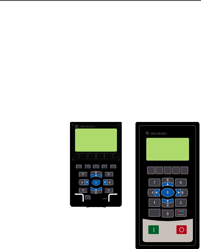
There are two types of enhanced PowerFlex 7-Class HIM:
•NEMA Type 1 (catalog number 20-HIM-A6)
•Remote-mount NEMA Type 4X/12 (catalog number 20-HIM-C6S), which also includes a 1202-C30 interface cable for connection to the drive
20-HIM-A6 HIM |
20-HIM-C6S HIM |
|
|


Rockwell Automation Publication 20HIM-UM001D-EN-P - February 2013 |
13 |

Chapter 2 Installing the HIM
Installing the 20-HIM-A6 HIM The 20-HIM-A6 (NEMA Type 1) HIM is normally installed in the HIM bezel (drive Port 1) on the front of the drive. For temporary hand-held operation, the
HIM can be plugged into drive Port 2 (near the bottom of the drive control pod for PowerFlex 750-Series drives, or on the bottom of the drive for PowerFlex 7- Class drives) using a 1 m/3.28 ft. long 20-HIM-H10 cable. For applications requiring the HIM to be located remotely, the HIM can be installed in a remotemount HIM bezel (catalog number 20-HIM-B1) in a suitable location. The 20- HIM-B1 remote-mount HIM bezel includes a 3 m/9.8 ft. long 1202-C30 cable.
In the Drive HIM Bezel
PowerFlex 750-Series IP20, NEMA/UL Open Type Drives
Place the HIM into the drive HIM bezel by inserting it straight back into the top of the bezel and then sliding it down into the base of the bezel onto the mating connector.
TIP |
The HIM can be installed in the drive HIM bezel with the drive powered or |
|
unpowered. |
20-HIM-A6 HIM |
DOWN |
IN |
Drive HIM Bezel |
(PowerFlex 755 drive shown)
14 |
Rockwell Automation Publication 20HIM-UM001D-EN-P - February 2013 |
Installing the HIM |
Chapter 2 |
|
|
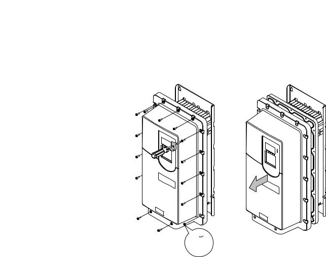
PowerFlex 750-Series IP54, NEMA/UL Type 12 Drives
1.Unfasten and remove the cover as shown below using the following recommended tools:
•Screwdriver: 6.4 mm (0.25 in.) flat or T20 Hexalobular
•Hex socket: 7 mm
2x:  M4 x 0.7
2.Place the HIM into the drive HIM bezel by inserting it straight back into the top of the bezel and then sliding it down into the base of the bezel onto the mating connector as shown on page 14.
3.Replace the cover and the fasteners.
4.Tighten all screws and nuts to the recommended torque of 0.68 N•m (6.0 lb•in).
Rockwell Automation Publication 20HIM-UM001D-EN-P - February 2013 |
15 |
Chapter 2 Installing the HIM
Using Drive Port 2 Connection for Hand-Held Operation
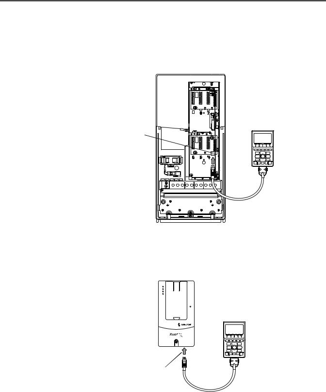
PowerFlex 750-Series Drive
Attach a 20-HIM-H10 cable to the bottom of the HIM. Then plug the other end of the cable into Port 2 near the bottom of the drive control pod.
(PowerFlex 755 drive shown with cover removed)
20-HIM-A6 HIM
Port 2
PE |
PE |
20-HIM-H10 Cable |
|
|
(1 m/3.28 ft. long) |
PowerFlex 7-Class Drive
Attach a 20-HIM-H10 cable to the bottom of the HIM. Then plug the other end of the cable into Port 2 on the bottom of the drive.
(PowerFlex 70
drive shown)
20-HIM-A6 HIM
Port 2
20-HIM-H10 Cable (1 m/3.28 ft. long)
16 |
Rockwell Automation Publication 20HIM-UM001D-EN-P - February 2013 |

Installing the HIM |
Chapter 2 |
|
|
In a Remote-Mount HIM Bezel (20-HIM-B1)
1.If the remote-mount HIM bezel is not mounted, see the HIM Bezel Installation Instructions, publication 20HIM-IN002, for mounting details.
2.Route the 3 m/9.8 ft. long 1202-C30 bezel cable (included with the 20- HIM-B1 remote-mount HIM bezel) to the drive.
3.Connect the bezel cable to the DPI Port 2 on the drive as shown on page 16 for a PowerFlex 750-Series drive or a PowerFlex 7-Class drive.
4.Install the HIM into the remote-mount HIM bezel.
PowerFlex 755 drive shown (without HIM in drive HIM bezel)
20-HIM-A6 HIM |
|
|
20-HIM-B1 |
|
|
Remote-Mount |
a. Push in. |
|
HIM Bezel |
||
|
||
|
b. Slide down. |
3 m/9.8 ft. long 1202-C30 bezel cable included  with 20-HIM-B1 remote-mount HIM bezel.
Distances can be increased up to 75 m/246 ft. (1)
(1)To increase this distance, use one of the following cables:
•1202-H03 Extension cable (0.3 m/0.98 ft. long)
•1202-H13 Extension cable (1.0 m/3.28 ft. long)
•1202-H30 Extension cable (3.0 m/9.8 ft. long)
•1202-CBL-KIT-100M cable
Note that a cable distance greater than 30 m/98.4 ft. is not CE compliant.
Rockwell Automation Publication 20HIM-UM001D-EN-P - February 2013 |
17 |

Chapter 2 Installing the HIM
Installing the 20-HIM-C6S
HIM
The 20-HIM-C6S (NEMA Type 4X/12) HIM is designed for remote installation and includes a 3 m/9.8 ft. long 1202-C30 cable. See Figure 1 for overall HIM dimensions. Choose an appropriate location to mount the 20-HIM- C6S HIM. The distance between the HIM and drive can be increased up to 75 m/246 ft. by using a 1202-Hxx extension cable or 1202-CBL-KIT-100M cable kit. However, a cable distance greater than 30 m/98.4 ft. is not CE compliant.
Figure 1 - 20-HIM-C6S HIM Dimensions
Dimensions are in millimeters and (inches).
25.0 |
93.0 |
(0.98) |
(3.66) |
3.0 m/9.8 ft. long |
|
1202-C30 cable |
|
(included with |
|
20-HIM-C6S HIM) |
180.0 |
|
(7.08) |
1202-Hxx Extension Cable |
|
|
|
|
|
(supplied separately, and only |
|
|
|
|
1202-H03 = 0.3 m/0.98 ft. long |
|
|
|
|
||
|
|
|
|
1202-H10 = 1.0 m/3.28 ft. long |
|
needed if required distance |
|
|
|
|
|
|
|
|
|
1202-H30 = 3.0 m/9.80 ft. long |
|
exceeds 1202-C30 Cable length) |
|
|
|
|
1. Drill the required hole pattern in the panel. See Figure 2 for dimensions.
TIP |
A conversion template (part number 336745-C01), provided with the |
|
20-HIM-C6S HIM, includes a drilling pattern and mounting |
|
instructions to assist with HIM installation. |
18 |
Rockwell Automation Publication 20HIM-UM001D-EN-P - February 2013 |
Installing the HIM |
Chapter 2 |
|
|
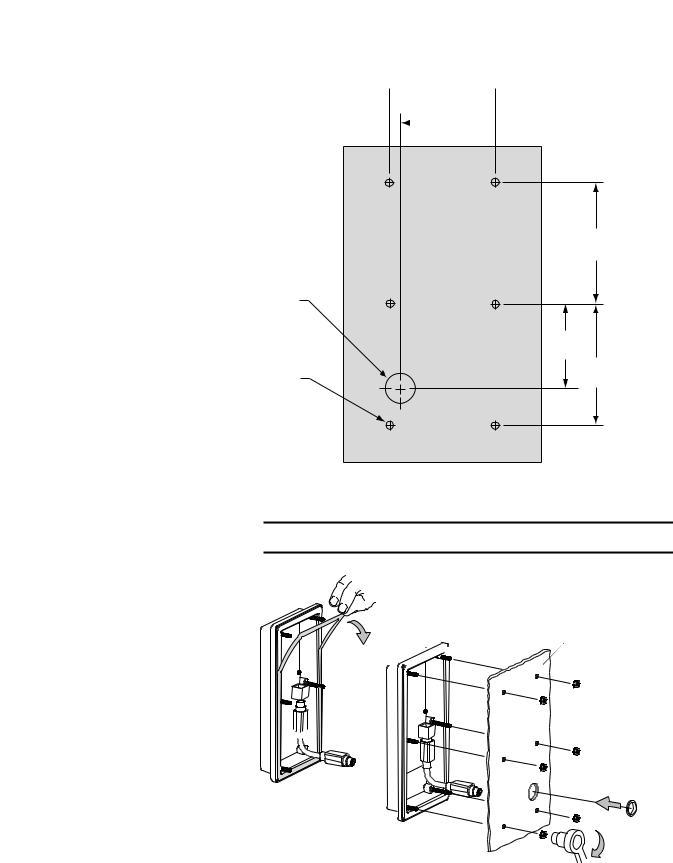
Figure 2 - Hole Pattern to Mount the 20-HIM-C6S HIM
Ø 19.1 (0.75)
Ø 4.8 (0.19)
Dimensions are in millimeters and (inches).
67.0
 (2.63)
  60.0
60.0
 (2.36)
Front View |
77.0 |
|
(3.03) |
59
(2.32)
77.0
(3.03)
2. Peel the protective film from the gasketed surface on the back of the HIM.
IMPORTANT Adhesive coated gasket is designed for one-time only installation.
Mounting Panel


0.68 N•m(6.0 lb•in)
Rockwell Automation Publication 20HIM-UM001D-EN-P - February 2013 |
19 |
Chapter 2 Installing the HIM
Removing the HIM
3.Insert the supplied 3 m/9.8 ft. long 1202-C30 HIM cable into the mating socket on the back of the HIM.
4.Install the supplied O-ring into the cable routing hole on the panel to protect the cable.
5.Route the HIM cable through the cable routing hole on the panel.
6.Align the six threaded studs of the HIM with the panel clearance holes, and place the HIM against the panel.
7.Tighten the nuts onto the six threaded studs of the HIM extending behind the panel.
Recommended torque is 0.68 N•m (6.0 lb•in).
8.Route the HIM cable to the drive.
9.Connect the HIM cable to the DPI Port 2 on the drive as shown on page 16 for a PowerFlex 750-Series drive or a PowerFlex 7-Class drive.
ATTENTION: Risk of injury or equipment damage exists. If the HIM cable or remote-mount HIM bezel cable is disconnected from DPI Port 2 on the drive, the drive may fault. Determine how the drive will respond before disconnecting the cable.
IMPORTANT The Host drive can remain powered when removing the HIM. However, a fault will occur if the HIM is not the last controlling device and does not have Manual control of the Host drive. To avoid a fault in this case, access the HIM Control screen (shown on page 28), press the  key, and then remove the HIM from the Host drive.
Remove the HIM from the drive HIM bezel or the remote-mount HIM bezel in reverse order of how it was installed.
20 |
Rockwell Automation Publication 20HIM-UM001D-EN-P - February 2013 |
Chapter 3
HIM Components
This chapter describes the components of the HIM.
Topic |
Page |
|
|
HIM Keypad |
21 |
|
|
LCD Display Elements |
24 |
|
|
Main Screens |
26 |
|
|
HIM Keypad
The keypad consists of soft keys, navigation and number keys, and single-function keys, which are described in their respective subsections that follow.
Soft Keys
The soft keys on the HIM are located at the top of the keypad and highlighted
below. Depending on the screen being displayed or the data entry mode being used, a soft key name and its function changes. When a dynamic soft key (up to a
maximum of five keys) is active, its present function and corresponding Soft Key Label (Figure 3) is shown at the bottom of the HIM screen. For a list of possible soft keys, their names, and corresponding functions, see Soft Key Labels on
page 25.
Rockwell Automation Publication 20HIM-UM001D-EN-P - February 2013 |
21 |

Chapter 3 HIM Components
Navigation and Number Keys
The five blue multi-function keys (2, 4, 5, 6, and 8) shown below are used to do the following:
•Enter their respective numeric value
•Scroll menus/screens
•Perform corresponding functions displayed in the Data Area (see page 24)
Multi-function Key |
Name |
Function |
|
2/Down Arrow |
• Enters the numeric value ‘2’. |
|
|
• Scrolls down to select an item. |
|
|
|
|
4/Left Arrow |
• Enters the numeric value ‘4’. |
|
|
• Scrolls left to select an item. |
|
|
|
|
5/Enter |
• Enters the numeric value ‘5’. |
•Displays the next level of a selected menu item.
•Enters new values.
•Performs intended actions.
6/Right Arrow |
• Enters the numeric value ‘6’. |
|
|
• Scrolls right to select an item. |
|
|
|
|
8/Up Arrow |
• |
Enters the numeric value ‘8’. |
|
• |
Scrolls up to select an item. |
The five gray number keys (0, 1, 3, 7, and 9) are used only to enter their respective numeric value.
22 |
Rockwell Automation Publication 20HIM-UM001D-EN-P - February 2013 |

HIM Components |
Chapter 3 |
|
|
Single-function Keys
There are four single-function keys, which are highlighted below and listed in the table below. Each single-function key always performs only its dedicated function.
Single-function Key |
Name |
Function |
|
Start |
Starts the drive. |
(1) |
Folders |
Accesses folders for parameters, diagnostics, memory functions, |
|
|
preferences, and other tasks. |
(1) |
Controls |
Accesses jog, direction, auto/manual, and other control functions. |
|
Stop |
• Stops the drive or clears a fault. |
•This key is always active.
•This key is controlled by drive parameter 307 [Start Stop Mode].
(1)During drive Start Up these keys are temporarily inactive.
Rockwell Automation Publication 20HIM-UM001D-EN-P - February 2013 |
23 |
Loading...