


 Loading...
User Manual
ArmorStart® Distributed Motor Controller with EtherNet/IP™
Catalog Numbers 280E, 281E, 284E
Important User Information
Because of the variety of uses for the products described in this publication, those responsible for the application and use of this control equipment must satisfy themselves that all necessary steps have been taken to assure that each application and use meets all performance and safety requirements, including any applicable laws, regulations, codes and standards.
The illustrations, charts, sample programs and layout examples shown in this guide are intended solely for purposes of example. Since there are many variables and requirements associated with any particular installation, Rockwell Automation does not assume responsibility or liability (to include intellectual property liability) for actual use based upon the examples shown in this publication.
Solid-state equipment has operational characteristics differing from those of electromechanical equipment. Safety Guidelines for the Application, Installation and Maintenance of Solid State Controls (Publication SGI-1.1 available from your local Rockwell Automation sales office or online at http://www.rockwellautomation.com/literature/) describes some important differences between solid-state equipment and hard-wired electromechanical devices. Because of this difference, and also because of the wide variety of uses for solid-state equipment, all persons responsible for applying this equipment must satisfy themselves that each intended application of this equipment is acceptable.
In no event will Rockwell Automation, Inc. be responsible or liable for indirect or consequential damages resulting from the use or application of this equipment.
The examples and diagrams in this manual are included solely for illustrative purposes. Because of the many variables and requirements associated with any particular installation, Rockwell Automation, Inc. cannot assume responsibility or liability for actual use based on the examples and diagrams.
No patent liability is assumed by Rockwell Automation, Inc. with respect to use of information, circuits, equipment, or software described in this manual.
Reproduction of the contents of this manual, in whole or in part, without written permission of Rockwell Automation, Inc., is prohibited.
Throughout this manual, when necessary, we use notes to make you aware of safety considerations.
WARNING: Identifies information about practices or circumstances that can cause an explosion in a hazardous environment, which may lead to personal injury or death, property damage, or economic loss.
ATTENTION: Identifies information about practices or circumstances that can lead to personal injury or death, property damage, or economic loss. Attentions help you identify a hazard, avoid a hazard, and recognize the consequence.
SHOCK HAZARD: Labels may be on or inside the equipment, for example, a drive or motor, to alert people that dangerous voltage may be present.
BURN HAZARD: Labels may be on or inside the equipment, for example, a drive or motor, to alert people that surfaces may reach dangerous temperatures.
IMPORTANT Identifies information that is critical for successful application and understanding of the product.
Trademark List
Allen-Bradley, ArmorConnect, ArmorStart, DeviceLogix, RSLogix 5000, RSNetWorx, StepLogic, RSLinx, On-Machine and ControlLogix are trademarks of Rockwell Automation, Inc.
Trademarks not belonging to Rockwell Automation are property of their respective companies.
European Communities (EC) Directive Compliance
If this product has the CE mark it is approved for installation within the European Union and EEA regions. It has been designed and tested to meet the following directives.
Low Voltage and EMC Directives
This product is tested to meet Council Directive 2006/95/EC Low Voltage Directive and Council Directive 2004/108/EC Electromagnetic Compatibility (EMC) by applying the following standard(s):
•Bulletin 280E/281E: EN 60947-4-1 — Low-voltage switchgear and controlgear — Part 4-1: Contactors and motorstarters — Electromechanical contactors and motor-starters.
•Bulletin 284E: EN 61800-5-1 — Adjustable speed electronic power drive systems — Part 5-1: Safety requirements
— Electrical, thermal and energy.
•Bulletin 284E: EN 61800-3 — Adjustable speed electronic power drive systems — Part 3: EMC product standard including specific test methods.
This product is intended for use in an industrial environment.

|
Table of Contents |
|
|
European Communities (EC) Directive Compliance. . . . . . . . . . . . . . . . . |
. 3 |
|
Low Voltage and EMC Directives. . . . . . . . . . . . . . . . . . . . . . . . . . . . . . . |
. 3 |
|
Chapter 1 |
|
Product Overview |
Introduction. . . . . . . . . . . . . . . . . . . . . . . . . . . . . . . . . . . . . . . . . . . . . . . . . . . . . |
16 |
|
Description . . . . . . . . . . . . . . . . . . . . . . . . . . . . . . . . . . . . . . . . . . . . . . . . . . . . . . |
16 |
|
Catalog Number Explanation . . . . . . . . . . . . . . . . . . . . . . . . . . . . . . . . . . . . . |
17 |
|
Operation . . . . . . . . . . . . . . . . . . . . . . . . . . . . . . . . . . . . . . . . . . . . . . . . . . . . . . . |
18 |
|
Mode of Operation. . . . . . . . . . . . . . . . . . . . . . . . . . . . . . . . . . . . . . . . . . . . . . . |
19 |
|
Bulletin 280E/281E . . . . . . . . . . . . . . . . . . . . . . . . . . . . . . . . . . . . . . . . . . |
19 |
|
Full-Voltage Start. . . . . . . . . . . . . . . . . . . . . . . . . . . . . . . . . . . . . . . . . . . . . |
19 |
|
Bulletin 284E . . . . . . . . . . . . . . . . . . . . . . . . . . . . . . . . . . . . . . . . . . . . . . . . |
19 |
|
Sensorless Vector Control . . . . . . . . . . . . . . . . . . . . . . . . . . . . . . . . . . . . . |
19 |
|
Description of Features . . . . . . . . . . . . . . . . . . . . . . . . . . . . . . . . . . . . . . . . . . . |
20 |
|
Overload Protection . . . . . . . . . . . . . . . . . . . . . . . . . . . . . . . . . . . . . . . . . . |
20 |
|
Embedded Switch Technology . . . . . . . . . . . . . . . . . . . . . . . . . . . . . . . . . . . . |
20 |
|
Switched vs. Unswitched |
|
|
Control Power Input/Output |
|
|
(I/O) Connections . . . . . . . . . . . . . . . . . . . . . . . . . . . . . . . . . . . . . . . . . . . . . . . |
21 |
|
EtherNet/IP™ Ports . . . . . . . . . . . . . . . . . . . . . . . . . . . . . . . . . . . . . . . . . . . . . . |
21 |
|
Embedded Web Server . . . . . . . . . . . . . . . . . . . . . . . . . . . . . . . . . . . . . . . . . . . |
22 |
|
E-mail Notification Configuration. . . . . . . . . . . . . . . . . . . . . . . . . . . . . |
22 |
|
EtherNet/IP LED Status Indication . . . . . . . . . . . . . . . . . . . . . . . . . . . . . . . |
22 |
|
Control Module LED Status |
|
|
and Reset . . . . . . . . . . . . . . . . . . . . . . . . . . . . . . . . . . . . . . . . . . . . . . . . . . . . . . . . |
22 |
|
Electronic Data Sheet (EDS) . . . . . . . . . . . . . . . . . . . . . . . . . . . . . . . . . . . . . . |
23 |
|
Fault Diagnostics. . . . . . . . . . . . . . . . . . . . . . . . . . . . . . . . . . . . . . . . . . . . . . . . . |
23 |
|
Protection Faults . . . . . . . . . . . . . . . . . . . . . . . . . . . . . . . . . . . . . . . . . . . . . |
23 |
|
Standard Features . . . . . . . . . . . . . . . . . . . . . . . . . . . . . . . . . . . . . . . . . . . . . . . . |
24 |
|
Inputs . . . . . . . . . . . . . . . . . . . . . . . . . . . . . . . . . . . . . . . . . . . . . . . . . . . . . . . |
24 |
|
Outputs . . . . . . . . . . . . . . . . . . . . . . . . . . . . . . . . . . . . . . . . . . . . . . . . . . . . . |
24 |
|
Gland Plate Entrance . . . . . . . . . . . . . . . . . . . . . . . . . . . . . . . . . . . . . . . . . |
25 |
|
Motor Cable . . . . . . . . . . . . . . . . . . . . . . . . . . . . . . . . . . . . . . . . . . . . . . . . . |
25 |
|
DeviceLogix™. . . . . . . . . . . . . . . . . . . . . . . . . . . . . . . . . . . . . . . . . . . . . . . . . |
25 |
|
Factory-Installed Options. . . . . . . . . . . . . . . . . . . . . . . . . . . . . . . . . . . . . . . . . |
25 |
|
Optional HOA Keypad Configuration (Bulletin 280E/281E only) 25 |
|
|
Optional HOA Selector Keypad with Jog Function |
|
|
(Bulletin 284E only) . . . . . . . . . . . . . . . . . . . . . . . . . . . . . . . . . . . . . . . . . . |
26 |
|
Source Brake Contactor and Connector (Bulletin 284E only) . . . . |
26 |
|
EMI Filter (Bulletin 284E only) . . . . . . . . . . . . . . . . . . . . . . . . . . . . . . . |
26 |
|
Dynamic Brake Connector (Bulletin 284E only) . . . . . . . . . . . . . . . . |
26 |
|
IP67 Dynamic Brake Resistor (Bulletin 284E only). . . . . . . . . . . . . . |
26 |
|
Output Contactor (Bulletin 284E only) . . . . . . . . . . . . . . . . . . . . . . . . |
27 |
|
Shielded Motor Cable (Bulletin 284E only). . . . . . . . . . . . . . . . . . . . . |
27 |
Rockwell Automation Publication 280E-UM001B-EN-P - July 2012 |
5 |

Table of Contents |
|
|
|
ArmorStart® EtherNet/ |
|
|
IP Features. . . . . . . . . . . . . . . . . . . . . . . . . . . . . . . . . . . . . . . . . . . . . . . . . . . . . . . |
28 |
|
Notes: . . . . . . . . . . . . . . . . . . . . . . . . . . . . . . . . . . . . . . . . . . . . . . . . . . . . . . . . . . . |
29 |
|
Chapter 2 |
|
Installation and Wiring |
Receiving . . . . . . . . . . . . . . . . . . . . . . . . . . . . . . . . . . . . . . . . . . . . . . . . . . . . . . . . |
31 |
|
Unpacking . . . . . . . . . . . . . . . . . . . . . . . . . . . . . . . . . . . . . . . . . . . . . . . . . . . . . . . |
31 |
|
Inspecting. . . . . . . . . . . . . . . . . . . . . . . . . . . . . . . . . . . . . . . . . . . . . . . . . . . . . . . . |
31 |
|
Storing . . . . . . . . . . . . . . . . . . . . . . . . . . . . . . . . . . . . . . . . . . . . . . . . . . . . . . . . . . |
31 |
|
General Precautions . . . . . . . . . . . . . . . . . . . . . . . . . . . . . . . . . . . . . . . . . . . . . . |
32 |
|
Precautions for Bulletin 280E/281E Applications . . . . . . . . . . . . . . . . . . . |
32 |
|
Precautions for Bulletin 284E Applications . . . . . . . . . . . . . . . . . . . . . . . . . |
32 |
|
Dimensions . . . . . . . . . . . . . . . . . . . . . . . . . . . . . . . . . . . . . . . . . . . . . . . . . . . . . . |
33 |
|
Conduit Gland Entrance Bulletin 280E/281E . . . . . . . . . . . . . . . . . . |
33 |
|
Conduit Gland Entrance Bulletin 284E . . . . . . . . . . . . . . . . . . . . . . . . |
34 |
|
ArmorConnect® Gland Connectivity Bulletin 280E/281E . . . . . . . |
35 |
|
ArmorConnect Gland Connectivity Bulletin 284E . . . . . . . . . . . . . . |
36 |
|
Mount Orientation. . . . . . . . . . . . . . . . . . . . . . . . . . . . . . . . . . . . . . . . . . . . . . . |
37 |
|
Operation . . . . . . . . . . . . . . . . . . . . . . . . . . . . . . . . . . . . . . . . . . . . . . . . . . . . . . . |
37 |
|
Wiring . . . . . . . . . . . . . . . . . . . . . . . . . . . . . . . . . . . . . . . . . . . . . . . . . . . . . . . . . . |
37 |
|
Power, Control, Safety Monitor Inputs, and Ground Wiring . . . . . |
37 |
|
Terminal Designations. . . . . . . . . . . . . . . . . . . . . . . . . . . . . . . . . . . . . . . . . . . . |
38 |
|
Control Power Wiring . . . . . . . . . . . . . . . . . . . . . . . . . . . . . . . . . . . . . . . . . . . . |
38 |
|
24V DC Control Power . . . . . . . . . . . . . . . . . . . . . . . . . . . . . . . . . . . . . . . |
39 |
|
ArmorStart with |
|
|
EtherNet/IP Internal Wiring. . . . . . . . . . . . . . . . . . . . . . . . . . . . . . . . . . . . . . |
40 |
|
Recommended Cord Grips . . . . . . . . . . . . . . . . . . . . . . . . . . . . . . . . . . . . |
43 |
|
AC Supply Considerations for Bulletin 284E Units . . . . . . . . . . . . . . . . . |
43 |
|
Ungrounded and High Resistive Distribution Systems . . . . . . . . . . . |
43 |
|
Disconnecting MOVs . . . . . . . . . . . . . . . . . . . . . . . . . . . . . . . . . . . . . . . . . |
44 |
|
Group Motor Installations for USA and Canada Markets . . . . . . . . |
45 |
|
Wiring and Workmanship Guidelines . . . . . . . . . . . . . . . . . . . . . . . . . . |
45 |
|
Other System Design Considerations. . . . . . . . . . . . . . . . . . . . . . . . . . . |
46 |
|
Electromagnetic Compatibility (EMC) . . . . . . . . . . . . . . . . . . . . . . . . . . . . |
46 |
|
General Notes (Bulletin 284E only) . . . . . . . . . . . . . . . . . . . . . . . . . . . . |
46 |
|
Wiring. . . . . . . . . . . . . . . . . . . . . . . . . . . . . . . . . . . . . . . . . . . . . . . . . . . . . . . |
47 |
|
Grounding . . . . . . . . . . . . . . . . . . . . . . . . . . . . . . . . . . . . . . . . . . . . . . . . . . . . . . . |
47 |
|
Grounding Safety Grounds . . . . . . . . . . . . . . . . . . . . . . . . . . . . . . . . . . . . |
47 |
|
Grounding PE or Ground . . . . . . . . . . . . . . . . . . . . . . . . . . . . . . . . . . . . . |
48 |
|
Grounding Motors. . . . . . . . . . . . . . . . . . . . . . . . . . . . . . . . . . . . . . . . . . . . |
48 |
|
ArmorConnect Power Media. . . . . . . . . . . . . . . . . . . . . . . . . . . . . . . . . . . . . . |
48 |
|
Description . . . . . . . . . . . . . . . . . . . . . . . . . . . . . . . . . . . . . . . . . . . . . . . . . . |
48 |
|
ArmorConnect Connections . . . . . . . . . . . . . . . . . . . . . . . . . . . . . . . . . . . . . . |
50 |
|
ArmorConnect Cable Ratings . . . . . . . . . . . . . . . . . . . . . . . . . . . . . . . . . . . . . |
52 |
6 |
Rockwell Automation Publication 280E-UM001B-EN-P - July 2012 |

Table of Contents
|
Branch Circuit Protection Requirements for ArmorConnect |
|
|
Three-Phase Power Media. . . . . . . . . . . . . . . . . . . . . . . . . . . . . . . . . . . . . |
52 |
|
Ethernet and I/O Connections. . . . . . . . . . . . . . . . . . . . . . . . . . . . . . . . . . . . |
53 |
|
Power Connections . . . . . . . . . . . . . . . . . . . . . . . . . . . . . . . . . . . . . . . . . . . . . . |
53 |
|
Optional Locking Clip . . . . . . . . . . . . . . . . . . . . . . . . . . . . . . . . . . . . . . . . . . . |
55 |
|
Chapter 3 |
|
Introduction to EtherNet/IP and |
Terminology. . . . . . . . . . . . . . . . . . . . . . . . . . . . . . . . . . . . . . . . . . . . . . . . . . . . . |
57 |
Device Level Ring Technology |
Introduction to EtherNet/IP. . . . . . . . . . . . . . . . . . . . . . . . . . . . . . . . . . . . . . |
59 |
|
Linear Network Introduction . . . . . . . . . . . . . . . . . . . . . . . . . . . . . . . . . . . . . |
61 |
|
Device Level Ring (DLR) . . . . . . . . . . . . . . . . . . . . . . . . . . . . . . . . . . . . . . . . . |
62 |
|
Introduction . . . . . . . . . . . . . . . . . . . . . . . . . . . . . . . . . . . . . . . . . . . . . . . . . |
62 |
|
Number of Nodes on a |
|
|
DLR Network . . . . . . . . . . . . . . . . . . . . . . . . . . . . . . . . . . . . . . . . . . . . . . . . . . . |
64 |
|
Ethernet Switches . . . . . . . . . . . . . . . . . . . . . . . . . . . . . . . . . . . . . . . . . . . . . . . . |
64 |
|
Ethernet Media . . . . . . . . . . . . . . . . . . . . . . . . . . . . . . . . . . . . . . . . . . . . . . . . . . |
64 |
|
EtherNet/IP General |
|
|
Wiring Guideline . . . . . . . . . . . . . . . . . . . . . . . . . . . . . . . . . . . . . . . . . . . . . . . . |
65 |
|
Requested Packet |
|
|
Interval (RPI). . . . . . . . . . . . . . . . . . . . . . . . . . . . . . . . . . . . . . . . . . . . . . . . . . . . |
65 |
|
Chapter 4 |
|
Product Commissioning |
IP Address. . . . . . . . . . . . . . . . . . . . . . . . . . . . . . . . . . . . . . . . . . . . . . . . . . . . . . . |
67 |
|
Gateway Address . . . . . . . . . . . . . . . . . . . . . . . . . . . . . . . . . . . . . . . . . . . . . |
67 |
|
Subnet Mask . . . . . . . . . . . . . . . . . . . . . . . . . . . . . . . . . . . . . . . . . . . . . . . . . |
67 |
|
Configuring EtherNet/ |
|
|
IP Address. . . . . . . . . . . . . . . . . . . . . . . . . . . . . . . . . . . . . . . . . . . . . . . . . . . . . . . |
68 |
|
Manually Configure the Network Address Switches . . . . . . . . . . . . . |
68 |
|
Use the Rockwell Automation BootP/DHCP Utility . . . . . . . . . . . . . . . |
70 |
|
Save the Relation List . . . . . . . . . . . . . . . . . . . . . . . . . . . . . . . . . . . . . . . . . |
72 |
|
DHCP IP Support . . . . . . . . . . . . . . . . . . . . . . . . . . . . . . . . . . . . . . . . . . . . . . . |
73 |
|
Using the Rockwell Automation Embedded |
|
|
Web Server . . . . . . . . . . . . . . . . . . . . . . . . . . . . . . . . . . . . . . . . . . . . . . . . . . . . . . |
74 |
|
Internal Web Server . . . . . . . . . . . . . . . . . . . . . . . . . . . . . . . . . . . . . . . . . . |
74 |
|
Network Configuration. . . . . . . . . . . . . . . . . . . . . . . . . . . . . . . . . . . . . . . |
75 |
|
Parameter Configuration. . . . . . . . . . . . . . . . . . . . . . . . . . . . . . . . . . . . . . |
76 |
|
E-mail Notification Configuration. . . . . . . . . . . . . . . . . . . . . . . . . . . . . |
77 |
|
Device Connections . . . . . . . . . . . . . . . . . . . . . . . . . . . . . . . . . . . . . . . . . . . . . . |
78 |
|
Chapter 5 |
|
Rockwell Automation Publication 280E-UM001B-EN-P - July 2012 |
7 |

Table of Contents
Adding an ArmorStart to RSLogix 5000
Setup . . . . . . . . . . . . . . . . . . . . . . . . . . . . . . . . . . . . . . . . . . . . . . . . . . . . . . . . . . . . 79 Connect and Configure ArmorStart with Add-On-Profile (AOP) . . . . 82
Offline Connection. . . . . . . . . . . . . . . . . . . . . . . . . . . . . . . . . . . . . . . . . . . . . . . 83
General Tab . . . . . . . . . . . . . . . . . . . . . . . . . . . . . . . . . . . . . . . . . . . . . . . . . . 83 Connection Tab . . . . . . . . . . . . . . . . . . . . . . . . . . . . . . . . . . . . . . . . . . . . . . 84
Parameters Tab . . . . . . . . . . . . . . . . . . . . . . . . . . . . . . . . . . . . . . . . . . . . . . . 85
Online Connection. . . . . . . . . . . . . . . . . . . . . . . . . . . . . . . . . . . . . . . . . . . . . . . 85 Parameters Tab . . . . . . . . . . . . . . . . . . . . . . . . . . . . . . . . . . . . . . . . . . . . . . . 89
Module Info Tab . . . . . . . . . . . . . . . . . . . . . . . . . . . . . . . . . . . . . . . . . . . . . 90
Internet Protocol Tab . . . . . . . . . . . . . . . . . . . . . . . . . . . . . . . . . . . . . . . . . 91 Port Configuration Tab . . . . . . . . . . . . . . . . . . . . . . . . . . . . . . . . . . . . . . . 92
Network Tab. . . . . . . . . . . . . . . . . . . . . . . . . . . . . . . . . . . . . . . . . . . . . . . . . 93
Auto-Generated Tags . . . . . . . . . . . . . . . . . . . . . . . . . . . . . . . . . . . . . . . . . 94 Notes: . . . . . . . . . . . . . . . . . . . . . . . . . . . . . . . . . . . . . . . . . . . . . . . . . . . . . . . . . . 104
Chapter 6
Optional HOA Keypad Operation Introduction . . . . . . . . . . . . . . . . . . . . . . . . . . . . . . . . . . . . . . . . . . . . . . . . . . . . 105
Keypad Description. . . . . . . . . . . . . . . . . . . . . . . . . . . . . . . . . . . . . . . . . . . . . . 105
Keypad and HOA Disable. . . . . . . . . . . . . . . . . . . . . . . . . . . . . . . . . . . . . . . . 109
Notes: . . . . . . . . . . . . . . . . . . . . . . . . . . . . . . . . . . . . . . . . . . . . . . . . . . . . . . . . . . 110
Bulletin 280E/281E/284E Programmable Parameters
Chapter 7
Basic Setup Parameters. . . . . . . . . . . . . . . . . . . . . . . . . . . . . . . . . . . . . . . . . . . 111 Parameter Groups . . . . . . . . . . . . . . . . . . . . . . . . . . . . . . . . . . . . . . . . . . . . . . . 111 ArmorStart EtherNet/IP Parameters. . . . . . . . . . . . . . . . . . . . . . . . . . . . . . 113 Introduction . . . . . . . . . . . . . . . . . . . . . . . . . . . . . . . . . . . . . . . . . . . . . . . . 113 Parameter Programming. . . . . . . . . . . . . . . . . . . . . . . . . . . . . . . . . . . . . . 113 Bulletin 280E/281E . . . . . . . . . . . . . . . . . . . . . . . . . . . . . . . . . . . . . . . . . . . . . 113 Basic Status Group. . . . . . . . . . . . . . . . . . . . . . . . . . . . . . . . . . . . . . . . . . . 113
Produced Assembly Config Group . . . . . . . . . . . . . . . . . . . . . . . . . . . . 122 Starter Protection Group . . . . . . . . . . . . . . . . . . . . . . . . . . . . . . . . . . . . . 123
User I/O Configuration Group . . . . . . . . . . . . . . . . . . . . . . . . . . . . . . . 125
Miscellaneous Configuration Group. . . . . . . . . . . . . . . . . . . . . . . . . . . 129 Starter Display Group (Bulletin 280E/281E only) . . . . . . . . . . . . . . 130
Starter Setup Group (Bulletin 280E/281E only). . . . . . . . . . . . . . . . 132
Bulletin 284E . . . . . . . . . . . . . . . . . . . . . . . . . . . . . . . . . . . . . . . . . . . . . . . . . . . 133 Basic Status Group. . . . . . . . . . . . . . . . . . . . . . . . . . . . . . . . . . . . . . . . . . . 133
Produced Assembly Config Group . . . . . . . . . . . . . . . . . . . . . . . . . . . . 143
Starter Protection Group . . . . . . . . . . . . . . . . . . . . . . . . . . . . . . . . . . . . . 144 User I/O Configuration Group . . . . . . . . . . . . . . . . . . . . . . . . . . . . . . . 147 Miscellaneous Configuration Group. . . . . . . . . . . . . . . . . . . . . . . . . . . 150 Drive I/O Configuration Group (Bulletin 284E only) . . . . . . . . . . 152
8 |
Rockwell Automation Publication 280E-UM001B-EN-P - July 2012 |

Table of Contents
How to Configure an Explicit Message
Diagnostics
Drive Display Group (Bulletin 284E only). . . . . . . . . . . . . . . . . . . . . 154
Drive Setup Group (Bulletin 284E only) . . . . . . . . . . . . . . . . . . . . . . 160
Drive Advanced Setup Group (Bulletin 284E only). . . . . . . . . . . . . 164 Clear a Type 1 Fault and Restart the Drive. . . . . . . . . . . . . . . . . . . . . 175
Clear an Overvoltage, Undervoltage, or Heatsink OvrTmp Fault without Restarting the Drive . . . . . . . . . . . . . . . . . . . . . . . . . . . . . . . . . 176 How StepLogic Works. . . . . . . . . . . . . . . . . . . . . . . . . . . . . . . . . . . . . . . 188
StepLogic Settings . . . . . . . . . . . . . . . . . . . . . . . . . . . . . . . . . . . . . . . . . . . 188
Linear List of Parameters
for Bulletin 280E/281E and Bulletin 284E . . . . . . . . . . . . . . . . . . . . . . . . 193
Chapter 8
Programming ControlLogix® Explicit Message . . . . . . . . . . . . . . . . . . . . . 203
Explicit Messaging with ControlLogix . . . . . . . . . . . . . . . . . . . . . . . . 203
Setting Up the MSG Instruction. . . . . . . . . . . . . . . . . . . . . . . . . . . . . . 203
Formatting an Explicit Message . . . . . . . . . . . . . . . . . . . . . . . . . . . . . . . . . . 203
Performing Explicit Messages . . . . . . . . . . . . . . . . . . . . . . . . . . . . . . . . . . . . 205
Chapter 9
Overview . . . . . . . . . . . . . . . . . . . . . . . . . . . . . . . . . . . . . . . . . . . . . . . . . . . . . . . 207
Protection Programming . . . . . . . . . . . . . . . . . . . . . . . . . . . . . . . . . . . . . 207
Fault Display . . . . . . . . . . . . . . . . . . . . . . . . . . . . . . . . . . . . . . . . . . . . . . . . . . . 207
Clear Fault . . . . . . . . . . . . . . . . . . . . . . . . . . . . . . . . . . . . . . . . . . . . . . . . . . . . . 207
Fault Codes. . . . . . . . . . . . . . . . . . . . . . . . . . . . . . . . . . . . . . . . . . . . . . . . . . . . . 207
Fault Definitions . . . . . . . . . . . . . . . . . . . . . . . . . . . . . . . . . . . . . . . . . . . . . . . . 208
Short Circuit. . . . . . . . . . . . . . . . . . . . . . . . . . . . . . . . . . . . . . . . . . . . . . . . 208
Overload Trip. . . . . . . . . . . . . . . . . . . . . . . . . . . . . . . . . . . . . . . . . . . . . . . 208
Phase Loss . . . . . . . . . . . . . . . . . . . . . . . . . . . . . . . . . . . . . . . . . . . . . . . . . . 208
Phase Short . . . . . . . . . . . . . . . . . . . . . . . . . . . . . . . . . . . . . . . . . . . . . . . . . 209
Ground Fault . . . . . . . . . . . . . . . . . . . . . . . . . . . . . . . . . . . . . . . . . . . . . . . 209
Stall . . . . . . . . . . . . . . . . . . . . . . . . . . . . . . . . . . . . . . . . . . . . . . . . . . . . . . . . 209
Control Power . . . . . . . . . . . . . . . . . . . . . . . . . . . . . . . . . . . . . . . . . . . . . . 209
I/O Fault . . . . . . . . . . . . . . . . . . . . . . . . . . . . . . . . . . . . . . . . . . . . . . . . . . . 209
Over Temperature. . . . . . . . . . . . . . . . . . . . . . . . . . . . . . . . . . . . . . . . . . . 209
Phase Imbalance. . . . . . . . . . . . . . . . . . . . . . . . . . . . . . . . . . . . . . . . . . . . . 209
Over Current . . . . . . . . . . . . . . . . . . . . . . . . . . . . . . . . . . . . . . . . . . . . . . . 209
A3 Power Loss . . . . . . . . . . . . . . . . . . . . . . . . . . . . . . . . . . . . . . . . . . . . . . 210
Internal Communication Fault . . . . . . . . . . . . . . . . . . . . . . . . . . . . . . . 210
DC Bus Fault . . . . . . . . . . . . . . . . . . . . . . . . . . . . . . . . . . . . . . . . . . . . . . . 210
Electrically Erasable Programmable Read-Only Memory
EEPROM Fault . . . . . . . . . . . . . . . . . . . . . . . . . . . . . . . . . . . . . . . . . . . . . 210
Hardware Fault . . . . . . . . . . . . . . . . . . . . . . . . . . . . . . . . . . . . . . . . . . . . . 210
Rockwell Automation Publication 280E-UM001B-EN-P - July 2012 |
9 |

Table of Contents |
|
|
|
Restart Retries . . . . . . . . . . . . . . . . . . . . . . . . . . . . . . . . . . . . . . . . . . . . . . . |
210 |
|
Miscellaneous Faults . . . . . . . . . . . . . . . . . . . . . . . . . . . . . . . . . . . . . . . . . |
210 |
|
EtherNet/IP LED Status Indication . . . . . . . . . . . . . . . . . . . . . . . . . . . . . . |
211 |
|
Control Module LED |
|
|
Status and Reset . . . . . . . . . . . . . . . . . . . . . . . . . . . . . . . . . . . . . . . . . . . . . . . . . |
212 |
|
Control Module Fault |
|
|
LED Indications. . . . . . . . . . . . . . . . . . . . . . . . . . . . . . . . . . . . . . . . . . . . . . . . . |
213 |
|
Fault 11 Detail . . . . . . . . . . . . . . . . . . . . . . . . . . . . . . . . . . . . . . . . . . . . . . . . . . |
215 |
|
Resetting Device to |
|
|
Factory Defaults. . . . . . . . . . . . . . . . . . . . . . . . . . . . . . . . . . . . . . . . . . . . . . . . . |
216 |
|
Chapter 10 |
|
Troubleshooting |
Introduction . . . . . . . . . . . . . . . . . . . . . . . . . . . . . . . . . . . . . . . . . . . . . . . . . . . . |
223 |
|
Bulletin 280E/281E Troubleshooting . . . . . . . . . . . . . . . . . . . . . . . . . . . . . |
224 |
|
Bulletin 284E Troubleshooting . . . . . . . . . . . . . . . . . . . . . . . . . . . . . . . . . . . |
224 |
|
Fault Definitions . . . . . . . . . . . . . . . . . . . . . . . . . . . . . . . . . . . . . . . . . . . . |
224 |
|
DB1 Faults. . . . . . . . . . . . . . . . . . . . . . . . . . . . . . . . . . . . . . . . . . . . . . . . . . . . . . |
225 |
|
Operation and Troubleshooting of the DB1 - Dynamic Brake . . . |
225 |
|
DB1 Resistor Overtemperature Fault . . . . . . . . . . . . . . . . . . . . . . . . . . |
226 |
|
DB1 Overcurrent Fault . . . . . . . . . . . . . . . . . . . . . . . . . . . . . . . . . . . . . . |
226 |
|
DB1 Undercurrent Fault . . . . . . . . . . . . . . . . . . . . . . . . . . . . . . . . . . . . . |
226 |
|
DB1 Switch Fault. . . . . . . . . . . . . . . . . . . . . . . . . . . . . . . . . . . . . . . . . . . . |
227 |
|
DB1 Open Fault. . . . . . . . . . . . . . . . . . . . . . . . . . . . . . . . . . . . . . . . . . . . . |
227 |
|
DB1 VBus Link Fault . . . . . . . . . . . . . . . . . . . . . . . . . . . . . . . . . . . . . . . . |
228 |
|
DB1 Comm Fault . . . . . . . . . . . . . . . . . . . . . . . . . . . . . . . . . . . . . . . . . . . |
228 |
|
DB1 Thermal Warning . . . . . . . . . . . . . . . . . . . . . . . . . . . . . . . . . . . . . . |
228 |
|
Internal Drive Faults . . . . . . . . . . . . . . . . . . . . . . . . . . . . . . . . . . . . . . . . . |
229 |
|
Control Module Removal . . . . . . . . . . . . . . . . . . . . . . . . . . . . . . . . . . . . . . . . |
233 |
|
Installation of Control Module . . . . . . . . . . . . . . . . . . . . . . . . . . . . . . . |
233 |
|
Troubleshoot and General Solutions for Linear or DLR Networks. . . |
235 |
|
Specific Issues on Your DLR or Linear Network. . . . . . . . . . . . . . . . |
235 |
|
. . . . . . . . . . . . . . . . . . . . . . . . . . . . . . . . . . . . . . . . . . . . . . . . . . . . . . . . . . . . . . . . |
238 |
|
Chapter 11 |
|
Specifications for EtherNet/IP |
Bulletin 280E/281E . . . . . . . . . . . . . . . . . . . . . . . . . . . . . . . . . . . . . . . . . . . . . |
239 |
|
Motor Overload Trip Curves . . . . . . . . . . . . . . . . . . . . . . . . . . . . . . . . . |
243 |
|
Contactor Life Load Curves . . . . . . . . . . . . . . . . . . . . . . . . . . . . . . . . . . |
244 |
|
Bulletin 284E . . . . . . . . . . . . . . . . . . . . . . . . . . . . . . . . . . . . . . . . . . . . . . . . . . . |
247 |
|
Sensorless Vector Control (SVC) . . . . . . . . . . . . . . . . . . . . . . . . . . . . . |
249 |
|
Motor Overload Trip Curves . . . . . . . . . . . . . . . . . . . . . . . . . . . . . . . . . |
250 |
|
Chapter 12 |
|
10 |
Rockwell Automation Publication 280E-UM001B-EN-P - July 2012 |
Table of Contents
Accessories
Applying More Than One ArmorStart
Motor Controller in a Single Branch Circuit
on Industrial Machinery
CIP Information
Industrial Ethernet Media . . . . . . . . . . . . . . . . . . . . . . . . . . . . . . . . . . . . . . . 253 D Code Connectivity (M12) – 1585D . . . . . . . . . . . . . . . . . . . . . . . . 253
Sensor Media . . . . . . . . . . . . . . . . . . . . . . . . . . . . . . . . . . . . . . . . . . . . . . . . . . . 255
Sensor Wiring. . . . . . . . . . . . . . . . . . . . . . . . . . . . . . . . . . . . . . . . . . . . . . . 255 Motor and Brake Cables . . . . . . . . . . . . . . . . . . . . . . . . . . . . . . . . . . . . . . . . . 255
Sealing Caps . . . . . . . . . . . . . . . . . . . . . . . . . . . . . . . . . . . . . . . . . . . . . . . . . . . . 257
Other . . . . . . . . . . . . . . . . . . . . . . . . . . . . . . . . . . . . . . . . . . . . . . . . . . . . . . . . . . 257 Dynamic Braking Resistors. . . . . . . . . . . . . . . . . . . . . . . . . . . . . . . . . . . . . . . 259
Sensorless Vector Control (SVC) Minimum Resistance and
Recommended Modules for Option DB. . . . . . . . . . . . . . . . . . . . . . . 259 Bulletin 284E Option (-DB) – IP20 Resistor . . . . . . . . . . . . . . . . . . 260
Sensorless Vector Control (SVC) Recommended Dynamic Brake
Modules for Option DB1 (IP67 Resistor) . . . . . . . . . . . . . . . . . . . . . 261
Appendix A
Introduction. . . . . . . . . . . . . . . . . . . . . . . . . . . . . . . . . . . . . . . . . . . . . . . . . . . . 263
ArmorStart LT Product Family . . . . . . . . . . . . . . . . . . . . . . . . . . . . . . . . . . 264
Multiple-Motor Branch Circuits and Motor Controllers Listed for Group Installation – General . . . . . . . . . . . . . . . . . . . . . . . . . . . . . . . . . . . . . . . . . . . 265
Maximum Fuse Ampere Rating According to 7.2.10.4(1) and 7.2.10.4(2)
267
. . . . . . . . . . . . . . . . . . . . . . . . . . . . . . . . . . . . . . . . . . . . . .Complete Text 267
Explanatory Example . . . . . . . . . . . . . . . . . . . . . . . . . . . . . . . . . . . . . . . . . . . . 269
Input and Output Conductors of Bulletin 290E and 291E Controllers (a) 275
Input and Output Conductors of Bulletin 294E Controllers (b) . . . . 275
Combined Load Conductors (c). . . . . . . . . . . . . . . . . . . . . . . . . . . . . . . . . . 275
Appendix B
High Level Product Description. . . . . . . . . . . . . . . . . . . . . . . . . . . . . . . . . . 277
Product Codes and Name Strings . . . . . . . . . . . . . . . . . . . . . . . . . . . . . 277
CIP Explicit Connection Behavior . . . . . . . . . . . . . . . . . . . . . . . . . . . . . . . 277
EDS Files . . . . . . . . . . . . . . . . . . . . . . . . . . . . . . . . . . . . . . . . . . . . . . . . . . . 278
CIP Object Requirements . . . . . . . . . . . . . . . . . . . . . . . . . . . . . . . . . . . . . . . 278
Identity Object . . . . . . . . . . . . . . . . . . . . . . . . . . . . . . . . . . . . . . . . . . . . . . . . . 279
CLASS CODE 0x0001 . . . . . . . . . . . . . . . . . . . . . . . . . . . . . . . . . . . . . . 279
Assembly Object . . . . . . . . . . . . . . . . . . . . . . . . . . . . . . . . . . . . . . . . . . . . . . . . 281
CLASS CODE 0x0004 . . . . . . . . . . . . . . . . . . . . . . . . . . . . . . . . . . . . . . 281
I/O Assemblies. . . . . . . . . . . . . . . . . . . . . . . . . . . . . . . . . . . . . . . . . . . . . . 282
Connection Manager Object . . . . . . . . . . . . . . . . . . . . . . . . . . . . . . . . . . . . . 285
CLASS CODE 0x0006 . . . . . . . . . . . . . . . . . . . . . . . . . . . . . . . . . . . . . . 285
Class 1 Connections . . . . . . . . . . . . . . . . . . . . . . . . . . . . . . . . . . . . . . . . . 286
Rockwell Automation Publication 280E-UM001B-EN-P - July 2012 |
11 |

Table of Contents |
|
|
|
Exclusive Owner Connection . . . . . . . . . . . . . . . . . . . . . . . . . . . . . . . . . |
286 |
|
Listen Only Connection. . . . . . . . . . . . . . . . . . . . . . . . . . . . . . . . . . . . . . |
287 |
|
Class 3 CIP Connections . . . . . . . . . . . . . . . . . . . . . . . . . . . . . . . . . . . . . |
287 |
|
Discrete Input Point Object . . . . . . . . . . . . . . . . . . . . . . . . . . . . . . . . . . . . . . |
288 |
|
CLASS CODE 0x0008 . . . . . . . . . . . . . . . . . . . . . . . . . . . . . . . . . . . . . . |
288 |
|
Discrete Output Point Object . . . . . . . . . . . . . . . . . . . . . . . . . . . . . . . . . . . . |
288 |
|
CLASS CODE 0x0009 . . . . . . . . . . . . . . . . . . . . . . . . . . . . . . . . . . . . . . |
288 |
|
Parameter Object. . . . . . . . . . . . . . . . . . . . . . . . . . . . . . . . . . . . . . . . . . . . . . . . |
290 |
|
CLASS CODE 0x000F . . . . . . . . . . . . . . . . . . . . . . . . . . . . . . . . . . . . . . |
290 |
|
Parameter Group Object . . . . . . . . . . . . . . . . . . . . . . . . . . . . . . . . . . . . . . . . . |
291 |
|
CLASS CODE 0x0010 . . . . . . . . . . . . . . . . . . . . . . . . . . . . . . . . . . . . . . |
291 |
|
Discrete Input Group Object . . . . . . . . . . . . . . . . . . . . . . . . . . . . . . . . . . . . . |
292 |
|
CLASS CODE 0x001D. . . . . . . . . . . . . . . . . . . . . . . . . . . . . . . . . . . . . . |
292 |
|
Discrete Output Group Object . . . . . . . . . . . . . . . . . . . . . . . . . . . . . . . . . . . |
292 |
|
CLASS CODE 0x001E . . . . . . . . . . . . . . . . . . . . . . . . . . . . . . . . . . . . . . |
292 |
|
Control Supervisor Object . . . . . . . . . . . . . . . . . . . . . . . . . . . . . . . . . . . . . . . |
293 |
|
CLASS CODE 0x0029 . . . . . . . . . . . . . . . . . . . . . . . . . . . . . . . . . . . . . . |
293 |
|
Overload Object. . . . . . . . . . . . . . . . . . . . . . . . . . . . . . . . . . . . . . . . . . . . . . . . . |
295 |
|
CLASS CODE 0x002C . . . . . . . . . . . . . . . . . . . . . . . . . . . . . . . . . . . . . . |
295 |
|
Device Level Ring (DLR) Object . . . . . . . . . . . . . . . . . . . . . . . . . . . . . . . . . |
296 |
|
CLASS CODE 0x0047 . . . . . . . . . . . . . . . . . . . . . . . . . . . . . . . . . . . . . . |
296 |
|
Qos Object . . . . . . . . . . . . . . . . . . . . . . . . . . . . . . . . . . . . . . . . . . . . . . . . . . . . . |
297 |
|
CLASS CODE 0x0048 . . . . . . . . . . . . . . . . . . . . . . . . . . . . . . . . . . . . . . |
297 |
|
DPI Fault Object . . . . . . . . . . . . . . . . . . . . . . . . . . . . . . . . . . . . . . . . . . . . . . . . |
297 |
|
CLASS CODE 0x0097 . . . . . . . . . . . . . . . . . . . . . . . . . . . . . . . . . . . . . . |
297 |
|
DPI Alarm Object . . . . . . . . . . . . . . . . . . . . . . . . . . . . . . . . . . . . . . . . . . . . . . . |
301 |
|
CLASS CODE 0x0098 . . . . . . . . . . . . . . . . . . . . . . . . . . . . . . . . . . . . . . |
301 |
|
Interface Object . . . . . . . . . . . . . . . . . . . . . . . . . . . . . . . . . . . . . . . . . . . . . . . . . |
303 |
|
CLASS CODE 0x00B4 . . . . . . . . . . . . . . . . . . . . . . . . . . . . . . . . . . . . . . |
303 |
|
TCP/IP Interface Object. . . . . . . . . . . . . . . . . . . . . . . . . . . . . . . . . . . . . . . . . |
304 |
|
CLASS CODE 0x00F5 . . . . . . . . . . . . . . . . . . . . . . . . . . . . . . . . . . . . . . |
304 |
|
Ethernet Link Object . . . . . . . . . . . . . . . . . . . . . . . . . . . . . . . . . . . . . . . . . . . . |
305 |
|
CLASS CODE 0x00F6 . . . . . . . . . . . . . . . . . . . . . . . . . . . . . . . . . . . . . . |
305 |
|
Appendix C |
|
Using DeviceLogix |
DeviceLogix Programming . . . . . . . . . . . . . . . . . . . . . . . . . . . . . . . . . . . . . . . |
308 |
|
DeviceLogix Programming Example. . . . . . . . . . . . . . . . . . . . . . . . . . . . . . . |
308 |
|
Import and Export. . . . . . . . . . . . . . . . . . . . . . . . . . . . . . . . . . . . . . . . . . . . . . . |
314 |
|
Bulletin 284 - VFD Preset Speed Example . . . . . . . . . . . . . . . . . . . . . . . . . |
314 |
|
Operation. . . . . . . . . . . . . . . . . . . . . . . . . . . . . . . . . . . . . . . . . . . . . . . . . . . |
320 |
|
DeviceLogix Ladder Editor Example . . . . . . . . . . . . . . . . . . . . . . . . . . . . . . |
320 |
|
ArmorStart 280 and 281 Status Bits . . . . . . . . . . . . . . . . . . . . . . . . . . . |
320 |
|
Bulletin 280 and 281 ArmorStart Fault Bits. . . . . . . . . . . . . . . . . . . . |
321 |
|
Bulletin 280 and 281 ArmorStart Outputs . . . . . . . . . . . . . . . . . . . . . |
322 |
12 |
Rockwell Automation Publication 280E-UM001B-EN-P - July 2012 |

|
|
Table of Contents |
|
Bulletin 280 and 281 ArmorStart Produced Network Bits |
. . . . . . 322 |
|
Bulletin 284 ArmorStart Status Bits. . . . . . . . . . . . . . . . . . . . . |
. . . . . . 323 |
|
Bulletin 284 ArmorStart Fault Bits. . . . . . . . . . . . . . . . . . . . . . |
. . . . . . 323 |
|
Bulletin 284 ArmorStart Outputs. . . . . . . . . . . . . . . . . . . . . . . |
. . . . . . 324 |
|
Bulletin 284 ArmorStart Produced Network Bits . . . . . . . . |
. . . . . . 325 |
|
Appendix D |
|
PID Setup |
PID Loop . . . . . . . . . . . . . . . . . . . . . . . . . . . . . . . . . . . . . . . . . . . . . . . . |
. . . . . . 327 |
|
Exclusive Control . . . . . . . . . . . . . . . . . . . . . . . . . . . . . . . . . . . . . |
. . . . . . 327 |
|
Trim Control . . . . . . . . . . . . . . . . . . . . . . . . . . . . . . . . . . . . . . . . . |
. . . . . . 328 |
|
PID Reference and Feedback . . . . . . . . . . . . . . . . . . . . . . . . . . . |
. . . . . . 329 |
|
PID Deadband . . . . . . . . . . . . . . . . . . . . . . . . . . . . . . . . . . . . . . . . |
. . . . . . 330 |
|
PID Preload. . . . . . . . . . . . . . . . . . . . . . . . . . . . . . . . . . . . . . . . . . . |
. . . . . . 330 |
|
PID Limits. . . . . . . . . . . . . . . . . . . . . . . . . . . . . . . . . . . . . . . . . . . . |
. . . . . . 330 |
|
PID Gains . . . . . . . . . . . . . . . . . . . . . . . . . . . . . . . . . . . . . . . . . . . . |
. . . . . . 331 |
|
Guidelines for Adjusting the PID Gains . . . . . . . . . . . . . . . . . |
. . . . . . 331 |
|
Notes:. . . . . . . . . . . . . . . . . . . . . . . . . . . . . . . . . . . . . . . . . . . . . . . . . . . . |
. . . . . . 334 |
|
Appendix E |
|
StepLogic, Basic Logic and Timer/ |
StepLogic Using Timed Steps . . . . . . . . . . . . . . . . . . . . . . . . . . . . . . |
. . . . . . 336 |
Counter Functions |
StepLogic Sequence. . . . . . . . . . . . . . . . . . . . . . . . . . . . . . . . . . . . |
. . . . . . 336 |
|
StepLogic Using Basic Logic Functions . . . . . . . . . . . . . . . . . . . . . |
. . . . . . 336 |
|
Timer Function . . . . . . . . . . . . . . . . . . . . . . . . . . . . . . . . . . . . . . . . . . . |
. . . . . . 338 |
|
Counter Function. . . . . . . . . . . . . . . . . . . . . . . . . . . . . . . . . . . . . . . . . |
. . . . . . 338 |
|
StepLogic Parameters. . . . . . . . . . . . . . . . . . . . . . . . . . . . . . . . . . . . . . |
. . . . . . 339 |
|
Appendix F |
|
Renewal Parts |
Bulletin 280E/281E . . . . . . . . . . . . . . . . . . . . . . . . . . . . . . . . . . . . . . . |
. . . . . . 341 |
|
Control Module Renewal Part Product Selection. . . . . . . . . |
. . . . . . 341 |
|
Base Module Renewal Part Product Selection . . . . . . . . . . . . |
. . . . . . 342 |
|
Bulletin 284E . . . . . . . . . . . . . . . . . . . . . . . . . . . . . . . . . . . . . . . . . . . . . |
. . . . . . 344 |
|
Control Module Renewal Part Product Selection. . . . . . . . . |
. . . . . . 344 |
|
Base Module Renewal Part Product Selection . . . . . . . . . . . . |
. . . . . . 345 |
Rockwell Automation Publication 280E-UM001B-EN-P - July 2012 |
13 |

Table of Contents
14 |
Rockwell Automation Publication 280E-UM001B-EN-P - July 2012 |
Chapter 1
Product Overview
|
|
|
|
Bulletin |
280E/281E |
|
284E |
Type |
|
EtherNet/IP™ |
|
|
|
|
|
|
Horsepower Range: |
|
|
|
|
|
|
0.5…10 Hp (0.37…7.5 kW) |
|
|
— |
|
|
|
|
0.5…5 Hp (0.4…3.0 kW) |
— |
|
|
|
|
|
|
|
Starting Method: |
|
|
|
|
|
|
Full-Voltage and Reversing |
|
|
— |
|
|
|
|
Sensorless Vector Control |
— |
|
|
|
|
|
|
|
Environmental Rating: |
|
|
|
|
|
|
IP67/NEMA Type 4 |
|
|
|
|
|
|
|
|
Control Voltage: |
|
|
|
|
|
|
24V DC |
|
|
|
|
|
|
|
|
Operational Voltage Ratings: |
|
|
|
|
|
|
200…480V AC |
|
|
— |
|
|
|
|
380…480V AC |
— |
|
|
|
|
|
|
Rated for Group Motor Installations |
|
|
|
|
|
|
|
Local logic using DeviceLogix™ |
|
|
|
|
|
|
|
I/O Capability: |
|
|
|
|
|
|
|
Four Inputs |
|
|
|
|
|
|
|
Two Outputs |
|
|
|
|
|
|
|
|
Network Communications: |
|
|
|
|
|
|
EtherNet/IP™ |
|
|
|
|
|
|
|
LED Status Indication |
|
|
|
|
|
|
|
|
Gland Plate Entry: |
|
|
|
|
|
|
Conduit Entrance |
|
|
|
|
|
|
|
ArmorConnect Power Media |
|
|
|
|
|
|
|
Quick Disconnects (I/O, Communications, Motor |
|
|
|
Connection, Three-Phase and Control Power |
|
|
|
|
|
|
|
Extended Length Motor and Brake Cables |
|
|
|
|
|
|
|
|
Factory Installed Options: |
|
|
|
|
|
|
HOA Keypad |
|
|
|
|
|
|
|
Source Brake Contactor |
— |
|
|
|
|
|
|
Dynamic Brake Connector |
— |
|
|
|
|
|
|
Output Contactor |
— |
|
|
|
|
|
|
EMI Filter |
— |
|
|
|
|
|
|
Shielded Motor Cable |
— |
|
|
|
|
|
|
Rockwell Automation Publication 280E-UM001B-EN-P - July 2012 |
15 |

Chapter 1 Product Overview
Introduction
Description
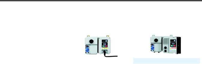
This chapter provides a brief overview of the features and functionality of the ArmorStart® EtherNet/Industrial Protocol (IP) Distributed Motor Controllers, Bulletin 280E, 281E, and 284E.
The ArmorStart EtherNet/IP™ Distributed Motor Controllers are integrated, pre-engineered, motor starting solutions. Bulletins 280E and 281E are used for full-voltage and reversing applications, respectively. Bulletin 284E is used in variable frequency applications where more precise motor control is needed. The ArmorStart EtherNet/IP controller offers a robust IP67/UL Type 4/12 enclosure design, which is suitable for water wash down environments.
ArmorStart EtherNet/IP includes an embedded dual port switch that supports device level ring (DLR) applications. It supports IEEE 1588 end-to-end transparent clock. This allows synchronization within a distributed network of devices. Transparent clocks in combination with enhanced or managed Ethernet switches are able to adjust for network introduced timing delays and improve the performance of motion applications.
The ArmorStart EtherNet/IP network address can be configured dynamically or statically via the embedded Web Server. In addition, the controller’s IP address can be manually set via three IP address switches found on the I/O section of the device.
The controller’s embedded Web Server allows the user to check status, diagnostics and perform simple device configuration using a standard web browser. It also supports SMTP protocol which allows the user to configure the device to send an alert e-mail of potential issues.
The ArmorStart Distributed Motor Controller is a modular “plug and play” design that offers simplicity in wiring and installation. The quick disconnects for the I/O, communications, and motor connections reduce the wiring time and eliminate wiring errors. The controller offers, as standard, four configurable (sink/source) DC inputs and two sourcing solid state outputs, to be used with sensors and actuators respectively, for monitoring and controlling the application process. The ArmorStart’s light-emitting diode (LED) status indication and built-in diagnostics capabilities allow ease of maintenance and troubleshooting. The optional Hand/Off/Auto (HOA) keypad configuration allows local start/ stop control.
An Add-on profile for ControlLogix® is available. Add-on profiles streamline the programming and installation by eliminating the task of individually configuring the device tags.
The copy and paste function allows easy configuration of multiple ArmorStarts Controllers. RSLogix™ 5000 revision 17.01 or later is required to implement addon profile support.
16 |
Rockwell Automation Publication 280E-UM001B-EN-P - July 2012 |
Product Overview |
Chapter 1 |
|
|
The Armorstart controller and associated motor cable have been evaluated as a system by UL and is suitable for group installation. Armorstart controllers contain a UL listed disconnect which in many applications eliminates the need for additional components.
Catalog Number Explanation Examples given in this section are for reference purposes. This basic explanation should not be used for product selection because not all combinations will
produce a valid catalog number.
Figure 1 - Catalog Number Explanation for 280E/281E
|
|
280 |
|
|
E – |
|
F |
|
12Z – |
10 |
|
|
C |
– CR – Option 1 |
||||||||||
|
|
a |
|
|
b |
|
|
c |
|
|
d |
|
e |
|
|
f |
|
g |
|
|
h |
|
||
|
|
a |
|
|
|
|
|
|
|
|
e |
|
|
|
|
|
|
|
|
h |
||||
|
|
|
|
|
|
|
|
|
|
|
|
|
|
|
|
|
||||||||
|
Bulletin Number |
|
|
|
|
|
|
|
Short Circuit Protection |
|
|
|
|
|
|
Option 1 |
||||||||
Code |
|
Description |
|
|
|
|
|
|
(Motor Circuit Protection) |
|
|
|
|
Code |
|
Description |
||||||||
|
|
|
|
|
|
|
|
|
Code |
|
|
Description |
|
|
|
|
|
|
|
|
|
|||
280 |
Full Voltage Starter |
|
|
|
|
|
|
|
|
|
3 |
Hand/Off/Auto Selector Keypad |
||||||||||||
|
|
10 |
|
|
|
10 A Rated Device |
|
|
|
|||||||||||||||
281 |
Reversing Starter |
|
|
|
|
|
|
|
|
|
3FR |
Hand/Off/Auto Selector Keypad with |
||||||||||||
|
|
|
|
|
|
|
|
|
25 |
|
|
|
25 A Rated Device |
|
|
|
|
Forward/Reverse |
||||||
|
|
|
|
|
|
|
|
|
|
|
|
|
|
|
||||||||||
|
|
|
|
|
|
|
|
|
|
|
|
|
|
|
|
|
|
|||||||
|
|
b |
|
|
|
|
|
|
|
|
f |
|
|
|
|
|
|
|
|
|
||||
|
|
|
|
|
|
|
|
|
|
|
|
|
|
|
|
|
|
|
|
|
|
|||
|
|
|
|
|
|
|
|
|
|
|
|
|
|
|
|
|
|
|
|
|
|
|||
|
|
|
|
|
|
|
|
|
|
|
|
|
|
|||||||||||
Code |
|
Description |
|
|
|
|
|
|
Overload Selection Current Range |
|
|
|
|
|||||||||||
E |
|
EtherNet/IP |
|
|
|
|
Code |
|
|
Description |
|
|
|
|
|
|
|
|
|
|||||
|
|
|
|
|
|
|
|
|
A |
|
|
0.24…1.2 A |
|
|
|
|
|
|
|
|
|
|||
|
|
c |
|
|
|
|
B |
|
|
0.5…2.5 A |
|
|
|
|
|
|
|
|
|
|||||
|
|
|
|
|
|
C |
|
|
1.1…5.5 A |
|
|
|
|
|
|
|
|
|
||||||
|
|
|
|
|
|
|
|
|
|
|
|
|
|
|
|
|
|
|
|
|||||
|
Enclosure Type |
|
|
|
|
|
|
|
|
|
|
|
|
|
|
|
||||||||
|
|
|
|
|
D |
|
|
3.2…16 A |
|
|
|
|
|
|
|
|
|
|||||||
Code |
|
Description |
|
|
|
|
|
|
|
|
|
|
|
|
|
|
|
|||||||
|
|
|
|
|
|
|
|
|
|
|
|
|
|
|
|
|
|
|
|
|
||||
F |
IP67/ UL Type 4/12 |
|
|
|
|
|
|
|
|
|
|
|
|
|
|
|
|
|
|
|||||
|
|
|
|
|
|
|
|
|
|
|
|
|
|
|
|
|
|
|
g |
|
|
|||
d
Contactor Size/Control Voltage
24V DC
12Z
23Z
Control and 3-Phase Power Connections/Motor Cable Connection (CR: Conduit/Round Media) or (RR: Round/Round Media)
|
|
|
|
Description |
|
|
Code |
|
|
|
|
|
Control Power |
3-Phase Power |
Motor Cable |
||
CR |
|
blank |
Conduit Entrance |
Conduit Entrance |
3 m, unshielded cordset |
|
male 90° |
||||
|
|
|
|
|
|
CR |
|
W* |
Conduit Entrance |
Conduit Entrance |
No cable |
RR |
|
blank |
Round Media (Male |
Round Media (Male |
3 m, unshielded cordset |
|
Receptacle) |
Receptacle) |
male 90° |
||
|
|
|
|||
RR |
|
W* |
Round Media (Male |
Round Media (Male |
No cable |
|
Receptacle) |
Receptacle) |
|||
|
|
|
|
||
* Refer to the Industrial Controls Catalog for extended motor cable lengths.
Rockwell Automation Publication 280E-UM001B-EN-P - July 2012 |
17 |

Chapter 1 Product Overview
Figure 2 - Catalog Number Explanation for 284E
284 E – F V D2P3 D – 10 – CR – Option 1 – Option 2 – Option 3
|
a |
b |
c |
d |
e |
f |
g |
h |
i |
j |
|
k |
|||
|
|
a |
|
|
|
|
d |
|
|
|
f |
|
|
|
i |
|
Bulletin Number |
|
|
|
Torque Performance Mode |
|
|
Control Voltage |
|
|
|
Option 1 |
|||
Code |
|
Description |
|
|
|
Code |
Description |
|
Code |
Description |
|
Code |
|
Description |
|
284 |
|
VFD Starter |
|
|
|
V |
Sensorless Vector Control |
|
Z |
24V DC |
|
3 |
Hand/Off/Auto Selector |
||
|
|
|
|
|
|
|
and Volts per Hertz |
|
|
|
|
|
Keypad with Jog Function |
||
|
|
b |
|
|
|
|
e |
|
|
|
g |
|
|
|
j |
|
|
|
|
|
|
|
|
|
|
|
|
||||
|
|
|
|
|
|
|
|
|
|
|
|
|
|||
|
Communications |
|
|
|
|
|
|
Short Circuit Protection (Motor |
|
|
|
||||
Code |
|
Description |
|
|
|
|
Output Current |
|
|
|
Circuit Protector) |
|
|
|
Option 2 |
E |
|
EtherNet/IP |
|
|
|
|
380…480V |
|
|
|
|
|
Code |
Description |
|
|
|
|
|
|
|
Code |
Description |
||||||||
|
|
|
|
|
|
Code |
Description |
|
10 |
10 A Rated Device |
|
DB |
blank |
DB Brake Connector |
|
|
|
c |
|
|
|
D1P4 |
1.4 A, 0.4 kW, 0.5 Hp |
|
25 |
25 A Rated Device |
|
DB1 |
blank |
Connectivity to IP67 |
|
|
|
|
|
|
D2P3 |
2.3 A, 0.75 kW, 1.0 Hp |
|
|
DB Resistor |
||||||
|
|
|
|
|
|
|
|
|
|
|
|||||
|
Enclosure Type |
|
|
|
|
|
|
|
|
|
|
|
|
Source Brake |
|
|
|
|
|
D4P0 |
4.0 A, 1.5 kW, 2.0 Hp |
|
|
|
|
SB |
blank |
||||
Code |
|
Description |
|
|
|
|
|
|
|
|
|
|
|
|
Contactor |
|
|
|
|
D6P0 |
6.0 A, 2.2 kW, 3.0 Hp |
|
|
|
|
|
|
||||
F |
|
Type 4 (IP67) |
|
|
|
|
|
|
|
SB |
W |
No cable |
|||
|
|
|
|
D7P6 |
7.6 A, 3.3 kW, 5.0 Hp |
|
|
|
|
||||||
|
|
|
|
|
|
|
|
|
|
|
|
|
|||
|
|
|
|
|
|
|
|
|
|
|
|
|
|||
|
|
|
|
|
|
|
|
|
|
|
|
|
|
|
|
h
Control and 3-Phase Power Connections / Motor Cable Connection (CR: Conduit/Round Media) or (RR: Round/Round Media)
|
|
|
|
Description |
|
|
Code |
Control Power |
3-Phase Power |
Motor Cable |
|
|
|
|
|
|
|
CR |
|
blank |
Conduit Entrance |
Conduit Entrance |
3 m, unshielded |
|
cordset male 90° |
||||
|
|
|
|
|
|
CR |
|
N |
Conduit Entrance |
Conduit Entrance |
3 m, shielded |
|
cordset male 90° |
||||
|
|
|
|
|
|
CR |
|
W |
Conduit Entrance |
Conduit Entrance |
No cable |
RR |
|
blank |
Round Media |
Round Media |
3 m, unshielded |
|
(Male Receptacle) |
(Male Receptacle) |
cordset male 90° |
||
|
|
|
|||
RR |
|
N |
Round Media |
Round Media |
3 m, shielded |
|
(Male Receptacle) |
(Male Receptacle) |
cordset male 90° |
||
|
|
|
|||
RR |
|
W |
Round Media |
Round Media |
No cable |
|
(Male Receptacle) |
(Male Receptacle) |
|||
|
|
|
|
||
|
|
|
|
|
|
|
k |
|
Option 3 |
Code |
Description |
EMI |
EMI Filter |
OC |
Output Contactor |
Operation
The ArmorStart Distributed Motor Controllers can operate three-phase squirrelcage induction motors as follows:
Bulletin 280E/281E: up to 10 Hp (7.4 kW) at 480V AC
Bulletin 284E: up to 5 Hp (3.0 kW) at 480V AC
ArmorStart EtherNet/IP Controllers accept 24V DC control voltage. The control voltage will provide power to inputs (unswitched) and outputs (switched). Unswitched control voltage is used to ensure no loss of sensor or other field input status under normal operation.
18 |
Rockwell Automation Publication 280E-UM001B-EN-P - July 2012 |

Product Overview |
Chapter 1 |
|
|
Mode of Operation |
Bulletin 280E/281E |
Full-Voltage Start
This method is used in applications requiring across-the-line starting, in which full inrush current and locked-rotor torque are realized. The ArmorStart Bulletin 280E offers full-voltage starting and the Bulletin 281E offers full-voltage starting for reversing applications.
Figure 3 - Full-Voltage Start
100%
Percent
Voltage
Time (seconds)
Bulletin 284E
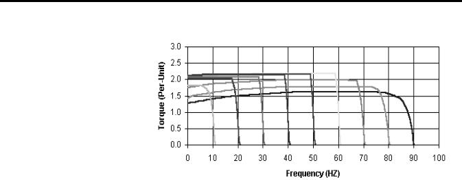
Sensorless Vector Control
Sensorless vector control provides exceptional speed regulation and very high levels of torque across the entire speed range of the drive. Features include:
•Autotune feature allows the Motor Controller to adapt to individual motor characteristics.
•Able to develop high torque over a wide speed range and adapts to individual motor characteristics.
•Embedded Variable Frequency Drive (VFD) control includes the Timer, Counter, Basic Logic and StepLogic® functions which can reduce hardware design costs and simplify control schemes.
•Integral PID (proportional, integral, differential) functionality enhances application flexibility.
Rockwell Automation Publication 280E-UM001B-EN-P - July 2012 |
19 |
Chapter 1 Product Overview
Description of Features
Embedded Switch
Technology
Figure 4 - Sensorless Vector Control
Overload Protection
The ArmorStart Distributed Motor Controller incorporates, as standard, electronic motor overload protection. This overload protection is accomplished
electronically with an I2t algorithm. The ArmorStart’s overload protection is programmable via the communication network, providing the user with flexibility.
The Bulletin 280E/281E overload trip class can be selected for class 10, 15, 20 protection. The Bulletin 284E overload trip class is Class 10 only. Ambient insensitivity is inherent in the electronic design of the overload (refer to Chapter 11 for the specification for overload trip curves).
ArmorStart EtherNet/IP includes embedded switch technology as standard. Each ArmorStart EtherNet/IP will consume one Common Industrial Protocol (CIP) connection. The ArmoStart will consume a Class 3 connection when RSLogix 5000 software displays the AOP.
In general, for a DLR or linear network keep individual segments to 50 nodes or less. In addition, it is important to reserve a minimum of 10% of available bandwidth to allow for processing of explicit messages.
Common features are:
•Designed according to the ODVA specification for EtherNet/IP. ODVA specification found at http://www.odva.org/
•Embedded switch technology is designed to enable end devices to form linear and ring network topologies
•Supports Device Level Ring (DLR) protocol
20 |
Rockwell Automation Publication 280E-UM001B-EN-P - July 2012 |
Product Overview |
Chapter 1 |
|
|
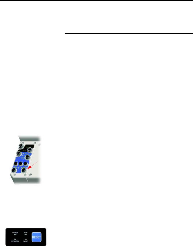
Switched vs. Unswitched Control Power Input/Output (I/O) Connections
EtherNet/IP™ Ports
•Supports IEEE 1588 transparent clock for CIP Motion™ and CIP Sync™ applications
•Supports the management of network traffic to ensure timely delivery of critical data, that is, QoS and IGMP protocols are supported
Note: DLR ports cannot be used as two network interface cards (NICs) connected to two different subnets.
The voltage at terminals A1/A2 supplies power to the Armorstart outputs. Removing this power or placing the Armorstart disconnect in the “OFF” position will disable the outputs.
The unswitched power A3/A2 supplies power to the input and communication module. This power is not affected by the state of the disconnect switch. This ensures that anytime the controller can communicate, the state of the inputs
is correct.
Figure 5 - Input and Output Configuration
ArmorStart EtherNet/IP includes a dual port Ethernet switch that supports 10/100 Mbps It utilizes a sealed D-coded micro (M12) style Ethernet connector. Dynamic Host Configuration Protocol (DHCP) is enabled as the factory default. Before using your adapter in an EtherNet/IP network you may need
to configure an IP address or set the address statically.
ATTENTION: To avoid unintended operation, the adapter must be assigned a fixed IP address. If a DHCP server is used, it must be configured to assign a fixed IP address for your adapter.
Failure to observe this precaution may result in unintended machine motion or loss of process control.
Rockwell Automation Publication 280E-UM001B-EN-P - July 2012 |
21 |
Chapter 1 Product Overview
Embedded Web Server
The embedded web server allows the user to view information and configure the ArmorStart via a web browser. The default Login is “Administrator”. There is no password set by default.
IMPORTANT |
Caution: The user should set the password to a unique value for authorized |
|
personnel. If the Login and password are lost you will need to reset the device to |
|
factory defaults via the Programmable Logic Controller (PLC). Note: The |
|
configuration will be lost. |
|
|
E-mail Notification Configuration
The embedded web server supports configuration of the Simple Mail Transfer Protocol (SMTP). Once properly configured, the motor controller will e-mail the user with specific fault/trip messages.
EtherNet/IP LED Status
Indication
EtherNet/IP LED status and diagnostics consists of four LEDs.
Figure 6 - EtherNet/IP LED
• Link Activity/Status LEDS
– Ethernet Link1 Activity/Status (Port 1) – LED Color: Bicolor
(Green/Yellow)
– Ethernet Link2 Activity/Status (Port 2) – LED Color: Bicolor
(Green/Yellow)
• “MOD” LED – Bicolor Red/Green represents the Ethernet Module status
• “NET” LED – Bicolor Red/Green represents the Ethernet Network status
Control Module LED Status |
|
|
and Reset |
The Control Module LED status and diagnostics consists of four status LEDs |
|
Figure 7 - LED Status |
||
and a Reset button. |
||
Indication and Reset |
|
|
|
• POWER LED |
|
|
The LED is illuminated solid green when switched (+A1/A2) control |
|
|
power is present and with the proper polarity. |
22 |
Rockwell Automation Publication 280E-UM001B-EN-P - July 2012 |

Product Overview |
Chapter 1 |
|
|
Electronic Data Sheet (EDS)
Fault Diagnostics
•RUN LED
This LED is illuminated solid green when a start command and control power are present.
•NETWORK LED
This bicolor (red/green) LED indicates the status of the internal communication link.
•FAULT LED
This indicates a Controller Fault (trip) condition.
The “Reset Button” is a local trip reset.
EtherNet/IP devices have electronic data sheets (EDS). These are specially formatted text files, as defined by the CIP™ Specifications, which represent the object model of the device. EDS files contain details about the readable and configurable parameters of the EtherNet/IP device. They also provide information about the I/O connections the device supports and the content of the associated data structures. EDS are used by EtherNet/IP device configuration tools, such as RSNetWorx™ for EtherNet/IP, and data servers such as RSLinx® Classic.
EDS files for all ArmorStart EtherNet/IP devices can also be uploaded directly from the device via the web server interface. Rockwell Automation product EDS files are also available on the internet at: http://www.ab.com/networks/eds.
Fault diagnostics capabilities built in the ArmorStart Distributed Motor Controller are designed to help you pinpoint a problem for easy troubleshooting and quick re-starting.
Protection Faults
Protection Faults are generated when potentially dangerous or damaging conditions are detected. Protection Faults are also known as “Trips.”
Rockwell Automation Publication 280E-UM001B-EN-P - July 2012 |
23 |

Chapter 1 Product Overview
Table 1 - Protection Faults
Bulletin 280E/281E Trip Status |
Bulletin 284E Trip Status |
PowerFlex 40 Fault Codes |
|
|
|
Short Circuit |
Short Circuit |
— |
|
|
|
Overload |
Overload |
(Drive Codes 7 and 64) |
|
|
|
Phase Loss |
Phase Short |
(Drive Codes 38…43) |
|
|
|
Reserved |
Ground Fault |
(Drive Code 13) |
|
|
|
Reserved |
Stall |
(Drive Code 6) |
|
|
|
Control Pwr Loss |
Control Pwr Loss |
— |
|
|
|
Input Fault |
Input Fault |
— |
|
|
|
Over Temperature |
Over Temperature |
— |
|
|
|
Phase Imbalance |
Over Current |
(Drive Codes 12 and 63) |
|
|
|
A3, Unswitched Power Loss |
A3, Unswitched Power Loss |
— |
|
|
|
Reserved |
Internal Comm |
(Drive Code 81) |
|
|
|
Reserved |
DC Bus Fault |
(Drive Codes 3, 4 and 5) |
|
|
|
EEprom |
EEprom |
(Drive Code 100) |
|
|
|
Hdw Flt |
Hdw Flt |
(Drive Codes 70 and 122) |
|
|
|
Reserved |
Restart Retries |
(Drive Code 33) |
|
|
|
Reserved |
Misc. Fault |
(Drive Codes 2, 8, 29, 48 and 80) |
|
|
|
Parameter Group “Start Protection,” Parameter 24 “PrFault Enable” is used to enable and disable the above protection faults. Refer to Parameter 61 “LastPR Fault” for additional details of the last protection fault.
Standard Features |
Inputs |
|
The EtherNet/IP version includes four 24V DC inputs that are single keyed (two |
|
inputs per connector) sourced from A3/A2 control power. The inputs use two |
|
M12 Connectors. Each input has an LED status indication. They are |
|
configurable as sinking or sourcing. |
Outputs
The EtherNet/IP version includes two self-protected solid state outputs that are single keyed (one per connector), sourced from A1/A2 control power. Outputs are sourcing type with a maximum current per output point of 0.5 A DC. The outputs use one M12 connectors per output, each having LED status indication.
24 |
Rockwell Automation Publication 280E-UM001B-EN-P - July 2012 |

Product Overview Chapter 1
Gland Plate Entrance
The ArmorStart product offers two different methods of connecting incoming three-phase and control power to the device. One method offered is the traditional conduit entrance with a 3/4 in. and a 1 in. conduit hole opening. The second method offers connectivity to the ArmorConnect® power media. Factoryinstalled receptacles are provided for connectivity to both three-phase and control power media.
Motor Cable
With every ArmorStart Distributed Motor Controller, a 3-meter unshielded 4-conductor cordset is provided with each unit as standard. If the optional Electromagnetic Interference (EMI) Filter is selected for Bulletin 284E units, a shielded 4-conductor cordset is provided with each unit as standard.
DeviceLogix™
DeviceLogix is a stand-alone Boolean program that resides within the ArmorStart Distributed Motor Controller. DeviceLogix is programmed locally using the Add-On Profile and implements Boolean math operations, such as, AND, OR, NOT, Timers, Counters, and Latches. DeviceLogix can run as a stand-alone application, independent of the network. However, 24V DC via A3 unswitched control power, must be maintained.
Factory-Installed Options |
Optional HOA Keypad Configuration (Bulletin 280E/281E only) |
|
The ArmorStart offers two optional factory-installed Hand/Off/Auto (HOA) |
|
configurations: Standard and Forward/Reverse HOA. |
|
Figure 8 - Optional HOA Configuration (Bulletin 280E left, 281E right) |
Rockwell Automation Publication 280E-UM001B-EN-P - July 2012 |
25 |

Chapter 1 Product Overview
Optional HOA Selector Keypad with Jog Function (Bulletin 284E only)
The HOA Selector Keypad with Jog Function allows for local start/stop control with capabilities to jog in forward/reverse motor directions.
Figure 9 - Optional HOA with Jog Function Configuration
Source Brake Contactor and Connector (Bulletin 284E only)
An internal contactor is used to switch the electromechanical motor brake On/ Off. The motor brake contactor is powered from the main power circuit. The configuration of the R1 relay controls the function of the brake. A customer accessible 2.5 A fuse is provided to protect the brake cable. Included is a 3-meter 3-pin cordset for connection to the motor brake as standard.
EMI Filter (Bulletin 284E only)
The EMI filter is required to be CE compliant. When selected, a 3-meter shielded 4-conductor motor cordset is provided as standard. This is only available with sensorless vector control.
Dynamic Brake Connector (Bulletin 284E only)
The user selectable DB Option includes a 3-meter, 3-pin cordset for connection to a IP20 dynamic brake module. See Chapter 11 for available dynamic brake modules.
Note: The IP67 Dynamic Brake Resistor cannot be used with the -DB factory-installed option.
IP67 Dynamic Brake Resistor (Bulletin 284E only)
The IP67 Dynamic Brake Resistor design offers simplicity in wiring and installation. The user selectable DB1 option provides the quick connector and an
26 |
Rockwell Automation Publication 280E-UM001B-EN-P - July 2012 |

Product Overview |
Chapter 1 |
|
|
internal resistor monitoring circuit board. The cable length available is 0.5 m and 1.0 m. The IP67 Dynamic Brake is separately ordered. See Chapter 11 for available IP67 Dynamic Brake Resistors.
Note: The IP67 Dynamic Brake Resistor is used only with the -DB1 factory-installed option. Only the specified IP67 Dynamic Brake resistor
can be used based on the VFD horsepower. Connecting resistors other than those specified will result in a DB1 fault.
Output Contactor (Bulletin 284E only)
An internal contactor is sourced from the 24V DC (A1/A2) control voltage to isolate the load side of the Bulletin 284E ArmorStart Distributed Motor
Controller. When control power is applied to A1/A2, the output contactor will close. When control power is removed, the output contactor will open. There is no other switching element that allows alternate control of the output contactor. A sequenced stop involving the output contactor cannot be performed.
Shielded Motor Cable (Bulletin 284E only)
If the EMI Filter is selected, a 3-meter shielded 4-conductor cordset is provided as standard.
Rockwell Automation Publication 280E-UM001B-EN-P - July 2012 |
27 |

Chapter 1 Product Overview
ArmorStart® EtherNet/
IP Features
Local Disconnect
IP Address Notation
2 Outputs (Micro/M12)
4 Inputs (Micro/M12)
IP Address Switches
Ethernet Ports (DLR)
Figure 10 - Bulletin 280E/281E ArmorStart with EtherNet/IP™
Communication Protocol
LED Status
 Indication and Reset
Control Module
 Hand-Off-Auto Keypad
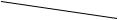 Motor Connection
Figure 11 - Bulletin 284E ArmorStart with EtherNet/IP Communication Protocol
Local Disconnect
 LED Status
Indication and Reset
IP Address Notation Area
 Control Module
2 Outputs (Micro/M12) 
 Hand-Off-Auto Keypad
4 Inputs (Micro/M12)
Source Brake Connection
IP Address Switches
Motor Connection
Ethernet Ports (DLR) 
28 |
Rockwell Automation Publication 280E-UM001B-EN-P - July 2012 |

Product Overview |
Chapter 1 |
|
|
Notes:
Rockwell Automation Publication 280E-UM001B-EN-P - July 2012 |
29 |

Chapter 1 Product Overview
30 |
Rockwell Automation Publication 280E-UM001B-EN-P - July 2012 |
Loading...