


AADvance
The Next Step in Automation
AADvance Controller
Solutions Handbook
Issue: 09
DOCUMENT: 553631 (ICSTT-RM447J_EN_P)

Solutions Handbook (AADvance Controller)
This page intentionally left blank
ii |
Document: 553631 |
|
(ICSTT-RM447J_EN_P) Issue: 09: |

Notice
In no event will Rockwell Automation be responsible or liable for indirect or consequential damages resulting from the use or application of this equipment. The examples given in this manual are included solely for illustrative purposes. Because of the many variables and requirements associated with any particular installation, Rockwell Automation does not assume responsibility or reliability for actual use based on the examples and diagrams.
No patent liability is assumed by Rockwell Automation, with respect to use of information, circuits, equipment, or software described in this manual.
Reproduction of this manual in whole or in part, without written permission of Rockwell Automation is prohibited.
All trademarks are acknowledged.
Disclaimer
It is not intended that the information in this publication covers every possible detail about the construction, operation, or maintenance of a control system installation. You should refer to your own (or supplied) system safety manual, installation instructions and operator/maintenance manuals.
Revision and Updating Policy
This document is based on information available at the time of its publication; however, the document contents are subject to change from time to time. You should contact Rockwell Automation Technical Support by e-mail — icstsupport@ra.rockwell.com to check if you have the latest version of this publication.
© Copyright Notice, Rockwell Automation 2012
This document contains proprietary information that is protected by copyright. All rights are reserved.
Documentation Feedback
Your comments will help us to serve your documentation needs better. If you discover any errors or have any suggestions on how to improve this publication send your comments to our product support group: icstsupport@ra.rockwell.com
This manual is applicable to Release R1.3 of the AADvance controller.
Document: 553631 |
iii |
(ICSTT-RM447J_EN_P) Issue: 09: |
|

Solutions Handbook (AADvance Controller)
Notes and Symbols used in this manual
This symbol calls attention to items which "must" be considered and implemented when designing and building an AADvance controller for use in a Safety Instrumented Function (SIF). It appears extensively in the AADvance Safety Manual.
Note: Notes are used extensively to provide important information about the product.
Standard Warnings and Cautions
WARNING ELECTRICAL ARCS AND EXPLOSION RISK IN HAZARDOUS AREAS
If you connect or disconnect wiring, modules or communications cabling while power is applied, an electrical arc can occur. This could cause an explosion in hazardous location installations. Do not remove wiring, fuses, modules or communications cabling while circuit is energized unless area is known to be non hazardous.
Failure to follow these instructions may result in personal injury.
WARNING MAINTENANCE
Maintenance must be carried out only by qualified personnel.
Failure to follow these instructions may result in personal injury.
CAUTION RADIO FREQUENCY INTERFERENCE
Most electronic equipment is influenced by Radio Frequency Interference. Caution should be exercised with regard to the use of portable communications equipment around such equipment. Signs should be posted in the vicinity of the equipment cautioning against the use of portable communications equipment.
CAUTION HEAT DISSIPATION AND ENCLOSURE POSITION
System and field power consumption by modules and termination assemblies is dissipated as heat. You should consider this heat dissipation on the design and positioning of your enclosure; e.g. enclosures exposed to continuous sunlight will have a higher internal temperature that could affect the operating temperature of the modules. Modules operating at the extremes of the temperature band for a continuous period can have a reduced reliability.
iv |
Document: 553631 |
|
(ICSTT-RM447J_EN_P) Issue: 09: |

Issue Record
Issue |
Date |
Comments |
01 |
Dec 2008 |
First Issue |
|
|
|
02 |
Feb 2009 |
|
03 |
Feb 2010 |
|
|
|
|
04 |
Mar 2010 |
Updates after peer review |
05 |
June 2010 |
updates for release 1.1.1 |
|
|
|
06 |
Oct 2010 |
updates to meet UL requirements |
07 |
Nov 2010 |
updates for ATEX and UL Certification and release 1.2 |
|
|
|
08 |
July 2012 |
Release 1.3 version |
09 |
Aug 2013 |
Changes to TUV certification topic, add On-line update |
|
|
|
|
|
feature and module specification data. |
|
|
|
|
|
|
|
|
|
Document: 553631 |
v |
(ICSTT-RM447J_EN_P) Issue: 09: |
|

Solutions Handbook (AADvance Controller)
Forward
This technical manual describes the features, performance and functionality of the AADvance controller and systems. It sets out some guidelines on how to specify a system to meet your application requirements.
Note: The AADvance controller is a logic solver. It uses processor modules and I/O modules. An AADvance system is formed by one or more controllers, their power sources, communications networks and workstations.
Who Should Use this Manual
This manual is intended primarily for system designers and technical sales people who need to understand the capabilities of an AADvance controller. This manual will assist you to design a suitable system.
The information contained in this manual is intended to be used in conjunction with (and not as a substitute for) expertise and experience in safety-related systems. In particular, it is expected that the reader has a thorough understanding of the intended application and can understand the generic terms used within this manual and the terminology specific to the integrator's or project's application area.
vi |
Document: 553631 |
|
(ICSTT-RM447J_EN_P) Issue: 09: |

Solutions Handbook (AADvance Controller)
Contents
Chapter 1 |
The AADvance System ........................................................................... |
|
1-1 |
The AADvance Controller.............................................................................................................................. |
|
1-1 |
|
Performance and Electrical Specifications.............................................................................................. |
|
1-3 |
|
Scan Times |
..................................................................................................................................................... |
|
1-4 |
Environmental .....................................................................................................................Specifications |
|
1-5 |
|
Controller ...................................................................................................................TUV Certification |
|
1-7 |
|
Certification ................................................................................for use in Hazardous Environments |
|
1-7 |
|
File No: E341697.......................................................................................................................................... |
|
1-7 |
|
File No: E251761.......................................................................................................................................... |
|
1-8 |
|
KCC-EMC ........................................................................................................................... |
Registration |
|
1-12 |
Main Components ........................................................................................................................................... |
|
1-13 |
|
Hardware Components............................................................................................................................ |
|
1-13 |
|
AADvance .......................Workstation Software and Application Development Environment |
1-14 |
||
Controller Functionality................................................................................................................................. |
|
1-16 |
|
SNTP............................................................................................................................................................. |
|
|
1-16 |
CIP over EtherNet/IP................................................................................................................................ |
|
1-16 |
|
HART............................................................................................................................................................ |
|
|
1-17 |
SNCP Safety ............................................................................................................................Networks |
|
1-18 |
|
Peer-to-Peer................................................................................................................................................ |
|
1-20 |
|
Serial Communication .............................................................................................................Interface |
|
1-22 |
|
Time Synchronization ................................................................................................................(SNTP) |
|
1-22 |
|
Modbus Master........................................................................................................................................... |
|
1-23 |
|
The OPC Portal ............................................................................................................................Server |
|
1-24 |
|
Controller .................................................................................................................IP Address Setting |
|
1-25 |
|
Recovery Mode .......................................................................................................................................... |
|
1-25 |
|
DiffServ Configuration .............................................................................................................................. |
|
1-25 |
|
Ethernet Forwarding ................................................................................................................................. |
|
1-26 |
|
Transparent .....................................................................................Communication Interface (TCI) |
|
1-27 |
|
Compiler Verification .....................................................................................................................Tool |
|
1-27 |
|
Technical Features........................................................................................................................................... |
|
1-28 |
|
TUV Approved .........................................................................................................Operating System |
|
1-28 |
|
Internal Diagnostics ................................................................................................................................... |
|
1-28 |
|
Controller .........................................................................................................Internal Bus Structure |
|
1-28 |
|
System Modification ...........................................................................................and On-line Updates |
|
1-29 |
|
ControlFLASH ......................................................................................................Firmware Upgrades |
|
1-31 |
|
Physical Features .............................................................................................................................................. |
|
1-32 |
|
Product Dimensions.................................................................................................................................. |
|
1-32 |
|
Compact Module ..........................................................................................................................Design |
|
1-33 |
|
Module Polarization .....................................................................................................................Keying |
|
1-34 |
|
Module Locking ....................................................................................................................Mechanism |
|
1-35 |
|
Termination ...........................................................................................................................Assemblies |
|
1-35 |
|
Ethernet, Serial ...................................................................................Data and Power Connections |
|
1-37 |
|
|
|
|
|
viii |
|
Document: 553631 |
|
|
|
(ICSTT-RM447J_EN_P) Issue: 09: |
|

Serial Communications............................................................................................................................. |
1-37 |
|
Field Wiring Connections........................................................................................................................ |
1-38 |
|
Corrective Maintenance and Module Replacement .......................................................................... |
1-38 |
|
Chapter 2 |
AADvance System Architectures.......................................................... |
2-1 |
SIL2 Architectures ............................................................................................................................................. |
2-1 |
|
SIL2 Fail-safe Architecture ......................................................................................................................... |
2-2 |
|
SIL2 Fault Tolerant Input Architectures................................................................................................. |
2-3 |
|
SIL2 Output Architecture .......................................................................................................................... |
2-4 |
|
SIL2 Fault Tolerant Input High Demand Architecture........................................................................ |
2-5 |
|
SIL3 Architectures ............................................................................................................................................. |
2-6 |
|
SIL3 Fail-safe I/O, Fault Tolerant Processor.......................................................................................... |
2-7 |
|
SIL3 Fault Tolerant I/O Architectures .................................................................................................... |
2-8 |
|
SIL3 TMR Input and Processor, Fault Tolerant Output ................................................................... |
2-10 |
|
Planned Certified Configurations................................................................................................................. |
2-11 |
|
Chapter 3 |
Building Architectures with TUV Approved Modules ......................... |
3-1 |
Fundamental Architectures ............................................................................................................................. |
3-1 |
|
Simplex I/O Architecture................................................................................................................................. |
3-1 |
|
Dual Architecture for Fault Tolerant Applications.................................................................................... |
3-5 |
|
Triple Modular Redundant Architecture ..................................................................................................... |
3-7 |
|
Chapter 4 |
Mixed Architectures................................................................................ |
4-1 |
Example Controllers ......................................................................................................................................... |
4-1 |
|
Mixed I/O Architectures.................................................................................................................................. |
4-3 |
|
Mixed Safety Integrity Levels........................................................................................................................... |
4-4 |
|
Distributed Architectures................................................................................................................................ |
4-5 |
|
Typical Network Applications ........................................................................................................................ |
4-6 |
|
Specifying a Safety Network...................................................................................................................... |
4-6 |
|
Controller Network Connectors............................................................................................................ |
4-7 |
|
Chapter 5 |
AADvance Scalability.............................................................................. |
5-1 |
I/O Channel Capacity........................................................................................................................................ |
5-1 |
|
Simplex I/O Channel Capacity .................................................................................................................. |
5-2 |
|
Dual I/O Channel Capacity........................................................................................................................ |
5-3 |
|
Triple Modular Redundant Channel Capacity....................................................................................... |
5-4 |
|
Adding I/O Channel Capacity ......................................................................................................................... |
5-5 |
|
Bus Connectors and Expansion Cable.......................................................................................................... |
5-5 |
|
Redundancy and Fault Tolerance ................................................................................................................... |
5-6 |
|
Expansion using Distributed Controllers..................................................................................................... |
5-6 |
|
Chapter 6 |
Specifying a New Controller .................................................................. |
6-1 |
Information to Specify a New Controller.................................................................................................... |
6-1 |
|
Define a New System ....................................................................................................................................... |
6-2 |
|
Choosing Termination Assemblies ................................................................................................................ |
6-5 |
|
Specify I/O Base Units....................................................................................................................................... |
6-5 |
|
Estimate AADvance Controller Weight ...................................................................................................... |
6-6 |
|
|
|
|
Document: 553631 |
ix |
(ICSTT-RM447J_EN_P) Issue: 09: |
|

Solutions Handbook (AADvance Controller)
Estimate Module Supply Power Dissipation and Field Loop Power Dissipation |
................................ 6-7 |
|
Chapter 7 |
Module Overview and Specifications ..................................................... |
7-1 |
T9110 Processor Module ................................................................................................................................ |
7-2 |
|
Processor Module Specification ............................................................................................................... |
7-4 |
|
T9100 Processor Base Unit............................................................................................................................. |
7-5 |
|
T9100 Base Unit Specification .................................................................................................................. |
7-7 |
|
T9300 I/O Base Unit (3 way) .......................................................................................................................... |
7-8 |
|
T9300 Base Unit Specification .................................................................................................................. |
7-9 |
|
T9310 Expansion Cable Assembly............................................................................................................... |
7-10 |
|
T9310 Extension Cable Specification .................................................................................................... |
7-11 |
|
T9401/2 Digital Input Module, 24V dc, 8/16 channel.............................................................................. |
7-12 |
|
T9401/2 Digital Input Module Specification......................................................................................... |
7-13 |
|
T9801/2/3 Termination Assemblies for Digital Inputs ............................................................................ |
7-14 |
|
T9801/2/3 Digital Input Termination Assembly Specification ......................................................... |
7-15 |
|
T9431/2 Analogue Input Module, 8/16 Channel....................................................................................... |
7-16 |
|
T9431/2 Analogue Input Module Specification ................................................................................... |
7-17 |
|
T9831/2/3 Termination Assemblies for Analogue Inputs....................................................................... |
7-18 |
|
T9831/2/3 Analogue Input Termination Assembly Specification.................................................... |
7-19 |
|
T9451 Digital Output Module, 24V dc, 8 channel ................................................................................... |
7-20 |
|
T9451 Digital Output Module Specification ........................................................................................ |
7-21 |
|
T9851/2 Termination Assemblies for Digital Outputs ........................................................................... |
7-22 |
|
T9851/2 Digital Output Termination Assembly Specifications....................................................... |
7-23 |
|
T9481/2 Analogue Output Module ............................................................................................................. |
7-24 |
|
T9481/2 Analogue Output Module Specification ............................................................................... |
7-25 |
|
T9881/2 Termination Assembly for Analogue Output Module............................................................ |
7-26 |
|
T9881/2 Analogue Output Termination Assembly Specification ................................................... |
7-27 |
|
Chapter 8 |
Application (Resource) Development ................................................... |
8-1 |
Programming Language Support..................................................................................................................... |
8-1 |
|
Program Management Facilities ...................................................................................................................... |
8-1 |
|
Support for Variable Types ............................................................................................................................. |
8-2 |
|
I/O Connection (Addressing of Physical I/O) ............................................................................................. |
8-2 |
|
Off-line Simulation and Testing ...................................................................................................................... |
8-2 |
|
Application (Resource) Program Security ................................................................................................... |
8-2 |
|
Aids to Software Development...................................................................................................................... |
8-3 |
|
AADvance Workbench Licensing Options ................................................................................................. |
8-3 |
|
DIN Rails Fitting |
................................................................................................................................................. |
8-4 |
Chapter 9 ............................................................................................ |
System Build |
9-1 |
Free Space Around ...............................................................................................................the Controller |
9-1 |
|
Base Units, DIN .........................................................................Rail installations and Expansion Cables |
9-3 |
|
Assemblies of Base .................................................................................................................................Units |
9-3 |
|
|
|
|
x |
Document: 553631 |
|
(ICSTT-RM447J_EN_P) Issue: 09: |
Power Supply Requirements ........................................................................................................................... |
9-4 |
|
Adding Cable Management.............................................................................................................................. |
9-4 |
|
Chapter 10 |
Parts List ................................................................................................ |
10-1 |
Chapter 11 |
Glossary of Terms ................................................................................. |
11-1 |
Chapter 12 |
Additional Resources ............................................................................ |
12-1 |
Document: 553631 |
xi |
(ICSTT-RM447J_EN_P) Issue: 09: |
|

Chapter 1
The AADvance System
An AADvance system consists of an AADvance controller, an external operator's workstation, field connections, power sources and external network connections. The flexibility of the design allows a system to be built to suit your own requirements from a standard range of modules and assemblies.
This chapter describes the main components that can be used to build an AADvance controller.
In This Chapter
The AADvance Controller |
............................................................................... 1-1 |
Main Components ............................................................................................ |
1-13 |
Controller Functionality.................................................................................. |
1-16 |
Technical Features............................................................................................ |
1-28 |
Physical Features ............................................................................................... |
1-32 |
The AADvance Controller
The AADvance controller is specifically designed for functional safety and critical control applications; it provides a flexible solution for your smaller scale requirements. The system can be used for safety implement functions as well as applications that are non-safety but still critical to a business process. This controller offers you the ability to create a cost-effective system to suit any of the following applications:
Critical process control
Fire and gas protection systems
Rotating machinery control systems
Burner management
Boiler and furnace control
Distributed process monitoring and control
The AADvance controller is a logic solver and I/O processing device that consists of processor modules, I/O modules and field termination assemblies that can easily be assembled and configured. A system is built up from one or more controllers, a combination of I/O modules, power sources, communications networks and user workstations. How you configure the system determines the type of application it can be used for.
An AADvance controller is particularly well suited to emergency shut down and fire and gas detection protection applications by providing a system solution with integrated and distributed fault tolerance. It is designed and validated to international standards and is certified by TÜV for functional safety control installations.
A Frequency Input Module (not yet released) will provide the functionality to meet the requirements of turbomachinary governor control and overspeed protection.
Document: 553631 |
1-1 |
(ICSTT-RM447J_EN_P) Issue: 09: |
|

Solutions Handbook (AADvance Controller)
The significant benefits of the AADvance controller are its performance and flexibility. Being designed to IEC 61508 it meets both SIL2 and SIL3 application requirements from the basic range of modules and mixed SIL rated applications can be covered by this range of modules.
All of the configurations are readily achieved by combining modules and assemblies without using special cables or interface units. System architectures are user configurable and can be changed without major system modifications. Processor and I/O redundancy is configurable so you can choose between fail safe and fault tolerant solutions. This scalability is user configurable, therefore, there is no change to the complexity of operations or programming if you choose to add redundant capacity to create a fault tolerant solution.
A controller is built from a range of compact plug-in modules that are straightforward to assemble into a system. They can be mounted onto DIN rails in a cabinet (see photograph) or directly mounted onto a wall in a control room. They do not require forced air cooling or special environmental control equipment. However, certain consideration to the cabinet type must be applied when used in hazardous environments.
A secure network communications protocol, developed by Rockwell Automation for the AADvance system, permits distributed control using new or existing network infrastructure while ensuring the security and integrity of the data. Individual sensors and actuators can connect to a local controller, minimizing the lengths of dedicated field cabling. There is no need for a large central equipment room; rather, the complete distributed system can be administered from one or more PC workstations placed at convenient locations.
1-2 |
Document: 553631 |
|
(ICSTT-RM447J_EN_P) Issue: 09: |

Single input modules are designed to meet SIL3 and in the most basic simplex configuration they offer a fail-safe solution. The AADvance system has comprehensive built-in diagnostics, while maintenance activities are straight forward operations which maximize system availability.
The AADvance controller is developed and built for IEC 61131 compliance and includes support for all five programming languages. Program access is secured by a removable "Program Enable" key. Simulation software lets you prove a new application before reprogramming and downloading, again maximizing system uptime.
Performance and Electrical Specifications
Table 1: |
Performance and Electrical Specifications |
|
|
|
|
|
|
|
Attribute |
Value |
|
|
Functional Characteristics |
|
|
|
|
|
|
|
Number of processor modules |
1 (non-safety applications, SIL1 and SIL2 safety |
|
|
|
applications) |
|
|
|
2 (SIL3 applications) |
|
|
|
3 (SIL3 fault tolerant and TMR applications) |
|
|
Maximum number of I/O modules |
48 modules (16 base units) - Two I/O busses each |
|
|
|
holds 24 modules (8 I/O base units) |
|
|
|
|
|
|
External interfaces |
Network (10/100BASE-TX Ethernet) |
|
|
|
Serial data communications (RS-485) |
|
|
Inter-controller links |
High integrity communications using Safety Network |
|
|
|
Control Protocol (SNCP) |
|
|
Application software support |
All IEC 61131 languages |
|
|
Displays |
Status LEDs on each module |
|
|
User controls |
Fault Reset button on each processor module |
|
|
Security |
Plug-in "Program Enable" key for access to application |
|
|
|
project and system configuration tools. |
|
|
Mounting |
DIN rail or flat panel |
|
|
Performance Characteristics |
|
|
|
Safety integrity level |
IEC 61508 SIL2 |
|
|
|
IEC 61508 SIL3 |
|
|
|
(depending on processor and I/O module |
|
|
|
configuration) |
|
|
|
|
|
|
Sequence of Event |
|
|
|
Processor Module (for internal |
|
|
|
variables) |
|
|
|
Event Resolution |
1ms |
|
|
Time Stamp Accuracy |
Application Scan |
|
|
Digital Input Module |
|
|
|
Event Resolution |
1ms |
|
|
|
|
|
|
|
|
|
Document: 553631 |
1-3 |
(ICSTT-RM447J_EN_P) Issue: 09: |
|

Solutions Handbook (AADvance Controller)
Time Stamp Accuracy |
10ms |
|
|
Safety accuracy limit |
200µA for Analogue Inputs and 1.0V dc for Digital |
|
Inputs. |
|
|
Electrical Characteristics |
|
|
|
Supply voltage |
Redundant 24V dc nominal, 18V dc to 32V dc range |
|
|
Channel isolation (channel to channel |
|
and channel to chassis) |
|
Maximum withstanding |
± 1.5kV dc withstand for one minute. |
Power consumption, heat dissipation and weight depend on the arrangement of the controller. You can estimate these values when you specify the controller using the tables provided in this manual.
A typical module surface temperature measured against a processor module is 43°C ± 2°C.
Scan Times
The following scan times were taken from a test system consisting of production modules.
Module |
Scan Time |
|
|
|
|
T9401 |
Digital input module, 24V dc, 8 channel |
|
|
Single |
1.23ms |
|
Dual |
1.73ms |
|
Triple |
2.08ms |
T9431 |
Analogue input module 24V dc, 8 channel |
|
|
Single |
1.26ms |
|
Dual |
1.91ms |
|
Triple |
2.33ms |
|
|
|
T9451 |
Digital output module, 24V dc, 8 channel |
|
|
Single |
1.43ms |
|
Dual |
2.44ms |
AADvance Workbench Sleep Period |
57.2ms |
|
Scan overhead per module |
0.09ms |
|
|
|
|
The tests did not measure the effect of logic complexity and communications loading. The scan time is:
(Number of module groups x scan time shown above) + Sleep Period + (Total modules x scan overhead)
The scan time will vary by up to +/- 5ms (not including the effect of logic and communications).
1-4 |
Document: 553631 |
|
(ICSTT-RM447J_EN_P) Issue: 09: |

Throughput time is the time from input change to output action. Due to the discrete nature of the scan, the throughput time will vary between one and two scans.
Note: The AADvance application scan time is limited to a minimum of 64ms to allow all processes to run. Small applications will report a scan time of approximately 57 - 61ms. Large applications may have longer scan times but each scan time will be consistent to within approximately 5ms.
An example configuration scan time:
T9431 Analogue input simplex modules x 30
T9451 Digital output simplex modules x 18
Total I/O modules |
= 48 |
Estimated scan time |
= (30 x 1.23ms) + (18 x 1.43ms) + 57.2ms + (48 x 0.09ms) |
|
= 125.1ms |
Throughput time: |
|
min |
= 125.1ms |
Avg |
= 187.6ms |
Max |
= 250.1ms |
Environmental Specifications
The following environmental specification defines the minimum recommended environmental conditions for an AADvance controller installation. Additional conditions apply to installations in a Hazardous environment.
Table 2: |
Environmental Specification |
|
|
|
|
|
|
|
Attribute |
Value |
|
|
Operating Temperature Range: |
|
|
|
For use in Hazardous Environments (UL |
|
|
|
Certification): |
|
|
|
Processor Modules |
–25 °C to 60 °C (–13 °F to 140 °F) |
|
|
I/O Modules and Assemblies |
–25 °C to 70 °C (–13 °F to 158 °F) |
|
|
For use in Non-Hazardous Environments |
|
|
|
(TUV Certification) |
|
|
|
All Modules and Assemblies |
–25 °C to 70 °C (–13 °F to 158 °F) |
|
|
Storage and Transport Temperature |
–40 °C to 70 °C (–40 °F to 158 °F) |
|
|
|
|
|
|
Module Surface Temperature (during normal |
43° C (109 °F) ± 2 °C |
|
|
operation) |
|
|
|
|
|
|
|
Humidity |
|
|
|
Operating |
10% to 95% RH, non-condensing |
|
|
|
|
|
|
Storage and Transport |
10% to 95% RH, non-condensing |
|
|
Vibration |
|
|
|
|
|
|
|
|
|
|
Document: 553631 |
1-5 |
(ICSTT-RM447J_EN_P) Issue: 09: |
|

Solutions Handbook (AADvance Controller)
|
Functional Stress |
5Hz to 9Hz |
|
|
|
|
|
|
Continuous |
1.7mm amplitude |
|
|
Occasional |
3.5mm amplitude |
|
|
|
|
|
|
Withstand |
10Hz to 150Hz |
|
|
Acceleration |
0.1g in 3 axes |
|
|
|
|
|
|
Endurance |
10Hz to 150Hz |
|
|
Acceleration |
0.5g in 3 axes |
|
|
|
|
|
|
Shock |
15g peak, 11ms duration, ½ sine |
|
|
Altitude |
|
|
|
|
|
|
|
Operating |
0 to 2000m (0 to 6,600 ft.) |
|
|
Storage and Transport |
0 to 3000m (0 to 10,000 ft.) |
|
|
|
This equipment must not be transported in |
|
|
|
unpressurized aircraft flown above 10,000 ft. |
|
|
Electromagnetic Interference |
Tested to the following standards: EN 61326- |
|
|
|
1:2006, Class A; EN 61326-3-1:2008, EN 54-4: |
|
|
|
1997, A1; EN 61131-2:2007; EN 62061:2005. |
|
|
|
|
|
|
Hazardous Location Capability |
Suitable for Class I Div 2 and Zone 2 |
|
|
|
|
|
Note:
Casing: Standard AADvance modules also have a plastic casing and are rated IP20: Protected against solid objects over 12mm (1/2in.) for example "fingers". There is no specific protection against liquids.
1-6 |
Document: 553631 |
|
(ICSTT-RM447J_EN_P) Issue: 09: |

Controller TUV Certification
TÜV Certification
TÜV is the safety certifying authority for an AADvance controller. The AADvance system is certified to the following standard:
|
|
|
|
|
|
|
|
|
IEC 61508, Part 1-7:1998-2000 |
|
EN 50178:1997 |
|
|
||||
|
|
|
|
|
|
|||
IEC 61511-1:2004 |
|
|
EN 50156-1:2004 |
|
||||
|
|
|
|
|||||
EN 61131-2:2007 |
|
|
EN 54-2:1997, A1:2006 (†) |
|||||
|
|
|
||||||
EN 61326-3-1:2008 |
|
NFPA 72:2007 |
|
|||||
|
|
|||||||
EN 61000-6-2:2005 |
|
NFPA 85:2007 |
|
|||||
|
|
|||||||
EN 61000-6-4:2007 |
|
NFPA 86:2007 |
|
|||||
(†) The analogue output modules are not certified to EN 54-2.
You can download a copy of the TUV certificate from www.tuvasi.com.
The Euro Controller version of the AADvance product is also tested to Q1 Extended Design levels of ISO 13628-6: 2006 Sub Sea Production Control System.
Certification for use in Hazardous Environments
The AADvance controller has been investigated and approved by UL (UL508) for use as Industrial Control Equipment in a general industrial environment and for use in hazardous locations, Class I, Division 2, Groups A, B, C and D. The UL file numbers are: E341697 and E251761.
File No: E341697
The AADvance controller investigation and approval is contained in the following files: NRAQ.E341697: Programmable Controllers investigated to ANSI/UL 508.
The products have been investigated using requirements contained in the following standards:
UL508, Industrial Control Equipment, Seventeenth edition, with revisions through and including April 15, 2010.
NRAQ7.E341697: Programmable Controllers Certified for Canada
The products have been investigated using requirements contained in the following standards:
CSA C22.2 No 142-M1987, Process Control equipment, Edition 1 - Revision date 1990-09-01
Document: 553631 |
1-7 |
(ICSTT-RM447J_EN_P) Issue: 09: |
|

Solutions Handbook (AADvance Controller)
Products Covered
The products investigated and approved:
Programmable Logic Controllers Models: 9110 Processor Module; 9401/2 Digital Output Module; 9431/2 Analogue Input module; 9451 Digital output module; 9482 Analogue Output Module.
Listed Accessories for use with PLCs: 9100 Processor Backplane, 9300 I/O Backplane, 9801 Digital Input Termination Assembly, Simplex; 9802 Digital Input Termination Assembly, Dual; 9803 Digital Input Termination Assembly, TMR; 9831 Analogue input Termination Assembly, Simplex; 9832, Analogue Input Termination Assembly, Dual; 9833 Analogue Input Termination Assembly, TMR 9851 Digital Output Termination Assembly, Simplex and 9852 Digital Output Termination Assembly, Dual; 9881 Analogue Output Termination Assembly, Simplex; 9882 Analogue Output Termination Assembly, Dual.
File No: E251761
The AADvance controller investigation and approval is contained in the following file certifications:
NRAG.E251761: Programmable Controllers for Use in Hazardous Locations Class I, Division 2, Groups A, B, C and D.
The products have been investigated using requirements contained in the following standards:
ANSI/ISA 12.12.01-20007, Nonincendive Electrical Equipment for use in Class I and II, Division 2 and Class III, Division 1 and 2 Hazardous Locations.
UL508, Industrial Control Equipment, Seventeenth edition, with revisions through and including April 15, 2010.
NRAG7.E251761: Programmable Controllers for Use in Hazardous Locations Certified for Canada; Class I, Division 2, Groups A, B, C and D
The products have been investigated using requirements contained in the following standards:
CSA C22.2 No 213-M1987, Nonincendive Control Equipment for Use in Class I, Division 2, Hazardous Locations.
CSA C22.2 No 142-M1987, Process Control equipment, Edition 1 - Revision date 1990-09-01
Products Covered
The products investigated and approved:
Programmable Logic Controllers Models: 9110 Processor Module; 9401/2 Digital Output Module; 9431/2 Analogue Input module; 9451 Digital output module; 9482 Analogue Output Module.
1-8 |
Document: 553631 |
|
(ICSTT-RM447J_EN_P) Issue: 09: |
Listed Accessories for use with PLCs: 9100 Processor Backplane, 9300 I/O Backplane, 9801 Digital Input Termination Assembly, Simplex; 9802 Digital Input Termination Assembly, Dual; 9803 Digital Input Termination Assembly, TMR; 9831 Analogue input Termination Assembly, Simplex; 9832, Analogue Input Termination Assembly, Dual; 9833 Analogue Input Termination Assembly, TMR 9851 Digital Output Termination Assembly, Simplex and 9852 Digital Output Termination Assembly, Dual; 9881 Analogue Output Termination Assembly, Simplex; 9882 Analogue Output Termination Assembly, Dual.
Document: 553631 |
1-9 |
(ICSTT-RM447J_EN_P) Issue: 09: |
|

Solutions Handbook (AADvance Controller)
Certificate
The AADvance controller modules have been evaluated to the requirements of EN 60079-0: 2009 and EN 60079-15: 2010 under Certificate Number: DEMKO 11 ATEX 1129711X .
1-10 |
Document: 553631 |
|
(ICSTT-RM447J_EN_P) Issue: 09: |

The AADvance controller has also been evaluated under certificate IECEx UL 12.0032X to the standards IEC 60079-0; (5th Edition) and IEC 60079-15 (4th Edition).
[ certificate to be supplied]
 For a system that is located in a Zone 2 Hazardous environment where ATEX certification is required, all modules should be installed in an ATEX and IECEx Certified, tool accessible IP54 enclosure. The enclosure is to be marked with the following: "Warning - Do not open when energized". After installation of the modules into the enclosure, access to termination compartments shall be dimensioned so that conductors can be readily connected. The modules and assemblies are for use in an area of not more than pollution degree 2 in accordance with IEC 60664-1
Module label
Document: 553631 |
1-11 |
(ICSTT-RM447J_EN_P) Issue: 09: |
|

Solutions Handbook (AADvance Controller)
KCC-EMC Registration
KCCEMC Registration
1-12 |
Document: 553631 |
|
(ICSTT-RM447J_EN_P) Issue: 09: |

Main Components
Hardware Components
Each controller is built from a standard range of modules and assemblies; it consists of processor modules, a processor base unit, digital and analogue I/O modules, I/O base units and termination assemblies all of which are assembled as follows:
A processor module is installed into a processor base unit that can hold up to 3 processor modules.
3-way I/O base units are connected to the processor base unit and to each other. Each I/O base unit holds up to three I/O modules and termination assemblies. A controller can have up to 8 I/O base units on each of two I/O busses, giving a total capacity for up to 48 I/O modules.
I/O modules are connected to field devices through external connectors on the termination assemblies.
The processor module and base units are designed for use as either single, dual or triple redundant processor module arrangements. The base processor base unit provides external connections for Serial and Ethernet networks and the dual redundant system power inputs.
The I/O base unit plugs directly into the processor base unit and carries the redundant system power for the modules, the processor commands across a command bus and I/O data across individual data response busses.
I/O base units also directly plug into each other and are secured and held in place by a clamping arm and retaining clips; hence, a controller becomes a complete mechanically and electrically interconnected assembly without the need for additional wiring or cabling. The I/O modules are also designed for use in single or dual or triple redundant configurations.
Termination assemblies are matched to a specific type of I/O module and have terminal blocks that provide 8 or 16 connections for the wiring to the field elements. The termination assemblies for dual and triple arrangements have channel to channel isolation. Termination assemblies for simplex input modules and termination assemblies for simplex and dual output modules are single ended (non-isolated) with a common return.
An expansion cable can be used to connect the processor base unit or an I/O base unit to another I/O base unit. This is useful for to breaking long runs of interconnected base units and provides some flexibility in the physical layout of a controller installation, particularly if the controller is installed in a cabinet.
Document: 553631 |
1-13 |
(ICSTT-RM447J_EN_P) Issue: 09: |
|

Solutions Handbook (AADvance Controller)
AADvance Workstation Software and Application Development Environment
Workstation Software
The AADvance workstation uses software that enables you to design the complete control strategy as one, then to target parts of the strategy at each controller. Interaction between the resources is automatic, significantly reducing the complexity of configuration in a multi-resource solution.
The workstation software, known as the Workbench is compliant with IEC61131 industrial standard and has the following powerful features:
the regulation of the flow of control decisions for an interacting distributed control system
providing for the consistency of data
providing a means for synchronous operation between devices
eliminating the need to have separate synchronous schemes
easing the development and maintenance of robust systems
The Workbench lets you create local and distributed control applications using the five languages of IEC 61131-3. Engineers can choose one language or a combination of languages that best suits their knowledge and programming style and the nature of the application.
It is also a secure development environment that requires a hardware (USB Dongle) or software license to run on a PC. There is also a Program Enable key (not applicable to a Euro Controller) that must be plugged into the processor base unit to allow the user to modify and download the application resource or access the AADvanceDiscover utility to check the status of the controller IP address. The Program Enable key when it is removed protects the application from unauthorized access.
The development environment includes:
tools for program development
program documentation
function block library management
application archiving
database configuration
import/export utilities
on-line monitoring
off-line simulation and controlled on-line changes.
1-14 |
Document: 553631 |
|
(ICSTT-RM447J_EN_P) Issue: 09: |
Programs can be simulated and tested and tested on the computer before downloading to the controller hardware. Also provided is a set of configuration tools that enables you to define the hardware architecture in the software; set up the processor functionality; and connect application variables to the Workbench application resource program that will monitor processor and I/O module status information and report I/O channel data values to the Workbench. Resource Control applications can be distributed across several hardware platforms, communicating with each other through secure networks.
CAUTION WORKBENCH FOR USE IN SAFETY APPLICATIONS
If the Workbench is used for safety related applications then you must follow the guidelines given in the AAdavnce Safety Manual (Doc No: 553630).
Operating System
The 9110 Processor Module must have an operating system with the following specification:
Windows XP with Service Pack 3
Windows Vista, Windows 7 & Server 2003 in both 32-bit and 64-bit versions
Note: Work Bench Licensing –Windows 64-bit version will only work with the USB Licensing option (dongle option).
Network port (10/100 Base T Ethernet)
Access to a CD-ROM drive, for software installation
Note: If the application adopts the USB (dongle) licensing option for the Workbench software, the processor module will also require one free USB port.
CAUTION WORKBENCH OPERATING SYSTEM
Do not use XP Professional x64 edition.
AADvanceDiscover Utility
The AADvanceDiscover utility is installed when you install the <DevelopmentSoftwareTools>, and appears on the Start menu of the computer. it displays a list of the <ProductName> controllers on the broadcast network, and reports a status for each one.
Importing and Exporting Data
The AADvance Workbench can import and export existing data in standard file formats such as Microsoft Excel.
Document: 553631 |
1-15 |
(ICSTT-RM447J_EN_P) Issue: 09: |
|

Solutions Handbook (AADvance Controller)
Controller Functionality
SNTP
The AADvance controller supports the Simple Network Time Protocol (SNTP) service that can circulate an accurate time around the network. As an SNTP client the controller will accept the current time from external Network Time Protocol (NTP) and SNTP network time servers.
SNTP clients settings tell the controller the IP address of the external server; the version of SNTP offered by the server; and the operating mode for the time synchronization signal that the processors will use for their real time clock.
An AADvance controller can also fulfill the role of one or more SNTP servers (one for each processor) to provide a network time signal throughout the network. To enable server time on an interface it is necessary to specify the direct broadcast address for that interface. This works for broadcast or unicast modes. This method of configuring is derived from the NTP configuration command language.
CIP over EtherNet/IP
The Common Industrial Protocol (CIP) over EtherNet/IP protocol enables AADvance controllers to exchange data with ControlLogix controllers programmed by RSLogix 5000. The exchange of data uses the produce/consume tag method currently used for sharing data between Logix-based controllers; this mechanism is similar to the variable bindings mechanism used by the AADvance controller.
The AADvance controller supports produce and consume communications to redundancy systems. The support for produce/consume variables is non-interfering; a failure of the EtherNet/IP stack will not interfere with the safe operation of the controller.
To use CIP over EtherNet/IP you have to first define a CIP network. Then you configure the exchange of data by defining a produce variable (or structure) for AADvance controller and a corresponding consume variable (or structure) for the ControlLogix controller. At runtime, the controller with the consume variable pulls data from the controller with the produce variable.
Note: The AADvance Controller will support the following number of connections and variables:
Connections: Maximum 255
A maximum of 128 producer and 128 consumer variables can be defined.
1-16 |
Document: 553631 |
|
(ICSTT-RM447J_EN_P) Issue: 09: |

Note: The CIP Protocol is intended to allow AADvance users to exchange data between AADvance controllers and the Allen Bradley Logix family controllers, using produce/consume messaging. Produce/Consume messaging does not support downloading to or for monitoring AADvance controllers. It is not recommended to use the CIP network to exchange data between AADvance controllers unless this is exclusively for non-safety data. The SNCP network should be used for Safety related data exchange between AADvance Controllers (see SNCP and variable Bindings in this publication).
HART
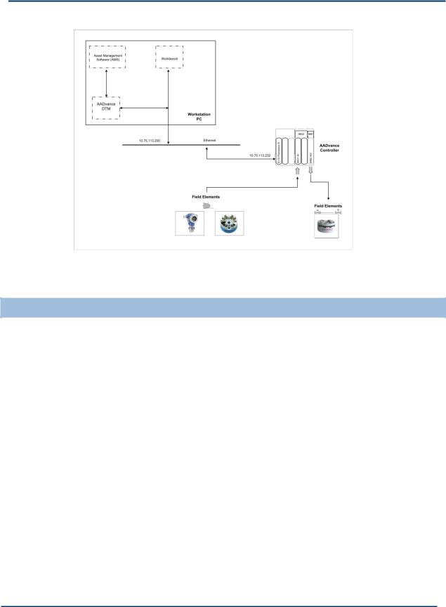
The AADvance controller supports utilizing dedicated HART modems on each analogue input and output channel allowing HART field device status, diagnostics and process data to be integrated into the application logic, thus increasing the level of SIF diagnostics significantly.
The AADvance analogue input/output modules use HART commands #03 to collect data from the field device as defined by Revision 5 of the HART specification. The application can be configured to use HART information to monitor and respond to device conditions. It may also be used to provide diagnostic information such as comparison and error reporting.
An additional feature of the AADvance controller is that it also combines with the AADvance DTM to enable asset management software (ASM) to communicate with HART devices.
Note: The AADvance system does not alter the messages passed between the asset management software and the field device and acts as a transport mechanism only.
AADvance HART Features
Provides passthru support for HART Standards 5, 6 and 7.
Variables can be configured for each Analogue input and output channel to monitor HART device information.
HART support is available on each Analogue Input or Output channel.
AADvance uses a single dedicated Ethernet port for HART passthru communication.
Supports the AADvance DTM provided by Rockwell Automation.
A typical HART set up is shown below:
Document: 553631 |
1-17 |
(ICSTT-RM447J_EN_P) Issue: 09: |
|
Solutions Handbook (AADvance Controller)
Figure 1: Example HART Pass-through System
SNCP Safety Networks
SNCP (Safety Network Control Protocol) is the Safety Protocol that allows elements of an AADvance System to exchange data. AADvance SNCP is a SIL 3 certified protocol which provides a safety layer for the Ethernet network making it a "Black Channel". Data is exchanged by creating a relationship between variables in different AADvance controllers; this is called "Binding Variables". Once variables are bound between controllers the SNCP protocol provides a transparent SIL 3 Certified layer allowing safety related data to be passed between AADvance controllers.
The bindings are based on a producer/consumer model. The controller consuming the data establishes a binding link with the Controller producing the data, and manages the entire exchange of data, including scheduling the data exchange, providing the diagnostics, managing the safety response in the event of faults and managing the communications redundancy.
SNCP Networks can be configured as Simplex (Fail Safe) or Redundant (Fault tolerant), the choice of network configuration is dependent on the applications safety and availability requirements. The data exchange is independent of the physical; network configuration as the connection between the controllers is treated as a logical network.
1-18 |
Document: 553631 |
|
(ICSTT-RM447J_EN_P) Issue: 09: |
 Loading...